1
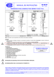
TERMOSTATI a tubo BOURDON Esecuzione STAGNA – Custodia INOX PT – C1 – 12 Rev. 6 12/2014 Serie/Series BOURDON tube TEMPERATURE SWITCHES WEATHERPROOF Execution – Stainless steel case IP pag. 1/4 Custodia / enclosure std. AISI 316L IP66 / NEMA 4X LVD TWG Low Voltage Directive Su richiesta / on request IECEx MINING Ex ia I Ma GAS Ex ia IIC T6/T4 Ga DUST Ex ia IIIC T85/T135 Da ATEX GOST R TR CU IM1 II 1 GD KCS KOSHA APPROVED IEC 61508 Termostato con capillare / temperature switch with capillary Per la terminologia usata in questo prospetto, v. PT-B0-20. CARATTERISTICHE GENERALI DELLA SERIE TWG Termostato diretto / temperature switch direct For terminology used in this data sheet, see PT-B0-20E. GENERAL FEATURES OF SERIES TWG COSTRUZIONE ELETTRICA: stagna. Grado di protezione IP66 (NEMA 4X) Classe sicurezza elettrica: classe I (EN61298-2:1997-06) Modo di protezione (opzionale): a sicurezza intrinseca MINIERE Ex ia I Ma GAS Ex ia IIC T6/T4 Ga POLVERI Ex ia IIIC T85/T135 Da ELECTRIC CONSTRUCTION: Weatherproof Degree of protection IP66 (NEMA 4X). Electrical safety class: class I (EN61298-2:1997-06) Protection mode (option): Intrinsically Safety MINING Ex ia I Ma GAS Ex ia IIC T6/T4 Ga DUST Ex ia IIIC T85/T135 Da CUSTODIA: Cassa e coperchio in lamiera di acciaio inossidabile AISI 316L con chiusura a baionetta e dispositivo di blocco idoneo per la piombatura, che è effettuata dall’installatore. Passaggio cavi: 1/2-14 NPT-F std. - opz. (vedi punto 5 a tergo). Morsettiera: terminali a vite adatti per capicorda. Materiale isolante PA (UL 94V-0). Viti di messa a terra: una interna e una esterna. 2 Sezione massima cavi di terra: 4 mm . Targa: in acciaio inox con scritte indelebili, marcate con laser ENCLOSURE: Case and cover in AISI 316L stainless steel drawn sheet; bayonet cover fitted with tamper-resistant lock, suitable for plumbing, which is performed by the installer. Cable entry: 1/2-14 NPT-F std. - opt. (see point 5 overleaf). Terminal block: screw-type terminals suitable also for cable lugs. Insulating material PA (UL 94V-0). Earthing screws: one inside, one outside. 2 Max section of earthing wires: 4 mm . Data plate: in stainless steel with indelible data by laser marking. CONTATTI ELETTRICI: uno o due microinterruttori SPDT a ELECTRICAL CONTACTS: One or two microswitches SPDT with differenziale fisso; un microinterruttore SPDT a differenziale fixed dead band; one microswitch SPDT with adjustable dead regolabile (vedi punto 1 a tergo). band (see point 1 overleaf). La funzione DPDT viene svolta da due micro SPDT con scatto The function DPDT is obtained by two micro SPDT with simultaneous action to within 0,2% of span. simultaneo entro lo 0,2% ampiezza campo. THERMAL ELEMENT: inert gas filled system (classification SAMA ELEMENTO TERMOMETRICO: a riempimento di gas III B) consist of: (classificazione SAMA III B) costituito da: - Bulb AISI 316. - Bulbo in AISI 316. - Connection AISI 304 compression fitting with adjustable insertion - Attacco in AISI 304 scorrevole con premistoppa. length. - Capillare in AISI 316 con protezione flessibile inox. - Capillary AISI 316 with stainless steel flexible armor. CAMPI: da -30°C a +600°C (vedi punto 3 a tergo). RANGES: from -30°C a +600°C (see point 3 overleaf). PUNTO DI INTERVENTO: regolabile su tutto il campo. SET POINT: adjustable throughout the range. Due punti di intervento indipendenti (n° 2 contatti SPDT) con Two independent set points (n° 2 SPDT contacts) with a gap higher distanza maggiore del 5% del campo. RipetibiIità: migliore di 0,5% dell'ampiezza campo. than 5% of range. Regolazione interna del punto di intervento tramite vite con Repeatability: better than 0,5% of span. dispositivo antiallentamento. Internal set point calibration by means of adjustment screw with Nota: quando il punto d'intervento è vicino (meno del 10% anti-loosening device. dell'ampiezza campo) alla temperatura normale di funzionamento, lo Note: when the set point is close (less then 10% of span) to strumento deve essere installato in un luogo esente da vibrazioni e normal working temperature, the device must be installed in a non esposto ad urti accidentali. vibration free location, and mechanical shocks must be avoided. MONTAGGIO: verticale (attacco verso il basso): MOUNTING: vertical (with connection downwards): - Diretto, sensore tipo B. - Direct, sensor type B. - Distanziato con capillare, sensore tipo C: - Remote with capillary, sensors type C: - std. a parete tramite fori di fissaggio posti sulla piastra in AISI304. - std. at surface/wall by means of holes on the plate in AISI 304; - (opzione) su tubo da 2" (con staffa opz. In AISI 304); - (option) 2" pipe with bracket in AISI 304. ALTA QUALITÁ COSTANTE dal 1897 CONSTANT HIGH QUALITY since 1897 COMPANY WITH MANAGEMENT SYSTEM CERTIFIED BY DNV = ISO 9001 = = ISO 14001 = pag. 2/4 TEMPERATURA AMBIENTE (limite operativa ): -40/+85°C -40/+85°C AMBIENT TEMPERATURE (operative limit ): limite operativa in accordo a ISA S51.1 operative limit according to ISA S51.1 APPARECCHIATURA certificata in accordo a: EQUIPMENT certified according to: Directive LVD 2006/95 EC Su richiesta / on request: IECEx IEC 60079-0, -11, -26 ATEX Directive 94/9 EC Annex III , IV. Nota: doppia marcatura, ATEX e IECEx, su unica targa Note: double marking, ATEX and IECEx, on single plate KCS – KOSHA TR CU 012/2011 - GOST R IEC61508 Functional Safety: approved for use in SIL 2 safety related systems. MANUALE DI ISTRUZIONI: NI-401 INSTRUCTION MANUAL: NI-401E DIMENSIONI [mm] e PESI [ kg ] DIMENSIONS [mm] and WEIGHTS [ kg ] Remoto capillare: sensore tipo C / Remote capillary: sensor type C Diretto: sensore tipo B / Direct: sensor type B Peso / Weight: 2,2 kg (capillary 2m) + 0,1 kg each meter of capillary Peso / Weight: 2,0 kg A = attacco bulbo / bulb connection Nota per termostato sensore C con capillare K = lunghezza del capillare: 2 m, 4 m, 6 m, 8 m, 10 m La lunghezza di inserzione (quota Y, vedi disegno) può essere aumentata fino al valore (K150) mm. Si ridurrà quindi la lunghezza "K". Esempio: K=6 m, Ymax.= 6150 = 900 mm Connessioni elettriche e viti di regolazione Electrical connections and adjustment screws Vite di terra esterna E = passaggio cavi / cable entry Note for temperature switch with sensor C capillary K = length of capillary: 2 m, 4 m, 6 m, 8 m, 10 m The insertion length (dimension Y, see drawing) can be varied up to (K150) mm. The length K is reduced accordingly. Example: K=6 m, Ymax.= 6150 = 900 mm Chiusura a baionetta e dispositivo di blocco idoneo per la piombatura, che è effettuata dall’installatore. Bayonet cover fitted with tamper-resistant lock, suitable for plumbing, which is performed by the installer. External earth screw Vite di terra interna Internal earth screw Morsettiera Terminal block Vite di regolazione punto di intervento micro 1 e 2 Calibration screws of microswitch 1 and 2 I dati sono impegnativi solo su offerta scritta / Data are binding only on written quotation ETTORE CELLA SPA A division of the WIKA group Viale De Gasperi, 48 - I 20010 Bareggio - MILANO - ITALY Tel. +39 02 90361146 - Fax +39 02 90361331 PT-C1-12 R6 www.ecellaspa.com [email protected] pag. 3/4 PER ORDINARE precisare i dati: Codice modello - Campo di taratura - Filettatura attacco bulbo Filettatura passaggio cavi - Eventuali opz. - Versioni. TO ORDER specify: Model code - Setting range - Bulb connection thread – Cable entry thread - Options if any - Versions. Esempio / Example: TWGCUN - K 2 m - 0/100°C - 1/2-14 NPT-M - 1/2-14 NPT-F 1 CODICE MODELLO MODEL CODE CONSEGNA / DELIVERY CONSEGNA / DELIVERY TWG CARATTERISTICHE / FEATURES PORTATE (Carico resistivo) TIPO CONTATTI ELEC.RATINGS (resistive load) CONTACT TYPE CA / AC CC / DC Serie Series Diretto / direct Remoto / remote B C Contatti argento, in aria Silver contacts, in air UN DN Differenziale FISSO FIXED dead band 1.1 Sensore Sensor STD + 1 SETTIMANA / WEEK STD + 2 SETTIMANE / WEEKS US DS UO DO Contatti argento, sigillato in argon Silver contacts, argon sealed T amb -30/+70°C Contatti dorati, sigillato in argon Gold plated contacts, argon sealed T amb -30/+70°C --- 2A 24V 0,5A 125V 0,25A 220V 15A 250V 2A 24V 0,5A 220V 1A 125V 0,5A 24V 1A 125V 0,5A 24V 20A 250V 2A 24V 0,5A 220V Contatti dorati, in aria Gold plated contacts, in air UG DG UR 15A 250V Differenziale REGOLABILE Contatti argento ADJUSTABLE dead band Silver contacts Su targa strumento sono riportati solo dati sottolineati. On instrument nameplate, data underlined only 1.2 Contatti elettrici Electric Contacts 1 micro SPDT, code U 2 micro SPDT, code D 2 LUNGHEZZA CAPILLARE (solo sensore tipo "C") CAPILLARY LENGTH (Only sensor type "C ") 3 CAMPI di Taratura e lavoro; vedi tabella pagina seguente Setting and working RANGES; see table next page 4 ATTACCO BULBO BULB CONNECTION 1/2-14 NPT-M Opz. Opt. 5 PASSAGGIO CAVI CABLE ENTRY 1/2-14 NPT-F OPZ. ¾-14 NPT-F, G½, OPT.: G¾, M20x1,5-F 6 OPZIONI OPTIONS 7 K [m] 2 4 6 8 10 G1/2A-M, 3/4-14-NPT-M, G3/4A-M Pressacavo/ cable gland vedi / see PT-H3-11 Taratura del punto di intervento Staffa per montaggio su tubo da 2" Bulbo a spirale (campo -30/+70°C) Temperatura ambiente -60°C; applicabile a contatti ele. UN, DN, UG, DG, UR Bulbo diametro 9,5 mm (Y=195, X=135 mm) Lunghezza a richiesta del gambo per il montaggio diretto codice B (maggiore dello std. 145mm e max. 1m) Connettore 7 poli MIL DTL 5015 Connector 7 poles MIL DTL 5015 Set point calibration Yoke for 2" pipe mounting Helical bulb (range -30/+70°C) Ambient temperature -60°C; applicable to ele. contacts UN, DN, UG, DG, UR Bulb diameter 9,5 mm (Y=195, X=135 mm) Length on request of the stem for direct mounting code B (longer than the std. 145mm & max. 1m) VERSIONI SU RICHESTA NACE NACE + Off-Shore Off-Shore. VERSIONS ON REQUEST Ex-ia ATEX & IECEx Ex-ia GOST R Ex-ia KCS - KOSHA Ammonia. Tropical. Geothermal. SIL IEC 61508 micro US, UO only NACE compliance to MR0175 / ISO15156 and to MR0103: Utilizzare pozzetti termometrici a norma NACE. NACE compliance to MR0175 / ISO15156 and to MR0103: Use thermowells conform to NACE. Caratteristiche elettriche: Ui =30V; Ii =100mA; Pi =0,75W; Ci =0F; Li =0mH Electrical character.: Ui =30V; Ii =100mA; Pi =0,75W; Ci =0F; Li =0mH Recommended electrical contacts US, DS, UO, DO; allowed use of UR Contatti elettrici consigliati US, DS, UO, DO; ammesso l’uso di UR ALTA QUALITÁ COSTANTE dal 1897 CONSTANT HIGH QUALITY since 1897 COMPANY WITH MANAGEMENT SYSTEM CERTIFIED BY DNV = ISO 9001 = = ISO 14001 = pag. 4/4 3 CAMPI di Taratura, campo di lavoro, temperatura di prova Setting RANGES, working range, proof temperature La classificazione del sistema termometrico si basa su SAMA: CLASSE III B The classification of the thermal system is based on SAMA: CLASS III B SAMA: Scientific Apparatus Makers Association Differenziale / Dead band Campo di taratura Campo di lavoro (temperatura di prova) setting range working range (proof temperature) -30 / +70 0 / +100 0 / +160 °C Regolabile tra minmax Adjustable between minmax Fisso e inferiore a: Fixed and lower than: 1 contact, code UN, US,UO, UG 2 contacts, code DN, DS, DO, DG 1 contact code UR -40 / +70 (120) 4,5 4,5 1535 -40 / +100 (120) 4,5 4,5 1535 5 5 1835 -40 / +160 (190) °C °C °C 0 / +250 -40 / +250 (300) 6 6 2145 0 / +400 -40 / +400 (500) 10 10 3377 0 / +600 -40 / +600 (600) 17 17 50115 Con il sensore diretto tipo B: campo di lavoro max. 250°C / With sensor direct type B: max. working range 250°C Dimensioni bulbo / Bulb dimension X=102, Y=163 Campo disponibile solo con capillare sensore C / range available only with capillary sensor C I dati sono impegnativi solo su offerta scritta / Data are binding only on written quotation ETTORE CELLA SPA A division of the WIKA group Viale De Gasperi, 48 - I 20010 Bareggio - MILANO - ITALY Tel. +39 02 90361146 - Fax +39 02 90361331 PT-C1-12 R6 www.ecellaspa.com [email protected]