1
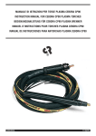
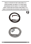
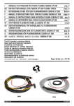
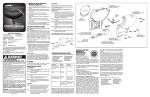
I
-MANUALE DI ISTRUZIONI PER TORCE PLASMA CEBORA CP 41C
pag. 2
GB -INSTRUCTION MANUAL FOR CEBORA CP41C PLASMA TORCH
page 4
D -BETRIEBSANLEITUNG FÜR DEN PLASMABRENNER CEBORA CP41C
Seite 6
F
-MANUEL D'INSTRUCTIONS POUR TORCHE PLASMA CEBORA CP41C
page 8
E
-MANUAL DE INSTRUCCIONES PARA ANTORCHA PLASMA CEBORA CP41C
pag. 10
Parti di ricambio
Spare parts
Ersatzteile
Pièces détachées
Partes de repuesto
Pag. 12
3.300.308
12/11/11
MANUALE DI ISTRUZIONI PER TORCIA PLASMA CEBORA CP-41C
Prima di utilizzare questa torcia, leggere attentamente il
presente manuale.
Questa torcia è costruita in stretta osservanza delle
prescrizioni in materia di sicurezza contenute nella
norma IEC 60974-7. In osservanza a quanto prescritto da tali norme, la CEBORA SPA dichiara che questa
torcia si deve utilizzare solo con generatori CEBORA.
I ricambi ed i particolari di consumo sono parti integrali della torcia, pertanto la CEBORA considera
manomissione della stessa l'utilizzo di particolari
NON ORIGINALI e declina quindi, in conformità allo
spirito della norma stessa, ogni responsabilità, comprese quelle previste dal contratto di garanzia.
Qualsiasi uso non descritto, è da considerarsi NON
AMMESSO.
La messa in funzione, l'uso e la manutenzione vanno
esercitati da personale qualificato.
Attenersi inoltre alle norme antinfortunistiche vigenti.
1 - PREMESSA
Questa torcia, progettata per il taglio di materiali elettroconduttori (metalli e leghe) mediante il procedimento ad
arco plasma, utilizza aria come gas plasma e di raffreddamento.
Il taglio ad "ARCO PLASMA" avviene per l'alta temperatura generata da un arco elettrico concentrato, quindi
possono innescarsi situazioni altamente pericolose. E'
indispensabile pertanto tenere nella massima considerazione il capitolo riguardante le PRECAUZIONI DI SICUREZZA descritto nel manuale del generatore al quale è
collegata la torcia.
Non è previsto, inoltre, che le torce debbano funzionare
sotto la pioggia o neve o in condizioni equivalenti.
Il presente manuale deve essere conservato con cura, in
un luogo noto all'operatore. Dovrà essere consultato
ogni volta che vi sono dubbi, dovrà seguire tutta la vita
operativa della macchina e dovrà essere impiegato per
l'ordinazione delle parti di ricambio.
2 DATI TECNICI
Corrente di taglio massima I2 = 40A D.C.
Fattore di servizio X = 35% con I2 = 40A.
Fattore di servizio X = 60% con I2 = 20A.
Tensione di lavoro U2 = 90V (ugello a contatto con il
pezzo).
Pressione di lavoro con cavo: 4m = 3,5 bar (0,35 MPa)
Portata aria totale = 60 litri/minuto.
3 SICUREZZA
Questa torcia è provvista di una sicurezza elettrica, posta
sul corpo torcia, per evitare che vi siano tensioni pericolose quando si sostituiscono l'ugello, l'elettrodo, il diffusore o il portaugello. E’ conforme alla norma IEC 609747 la quale prescrive che l'ugello posto verticalmente su
un piano orizzontale, essendo parte in tensione, non
possa essere toccato dal dito di prova convenzionale le
cui caratteristiche sono indicate dalla norma stessa.
2
4 MANUTENZIONE TORCIA
Togliere sempre l'alimentazione alla macchina prima di
ogni intervento che deve essere eseguito da personale
qualificato.
4.1 SOSTITUZIONE DELLE PARTI DI CONSUMO
(FIG. 1-2)
I particolari soggetti ad usura sono l'elettrodo G, il diffusore F e l'ugello E e devono essere sostituiti dopo aver
svitato il portaugello D.
L'elettrodo G deve essere sostituito quando presenta un
cratere al centro profondo circa 1 mm.
L'ugello E va sostituito quando presenta il foro centrale
rovinato o allargato rispetto a quello del particolare
nuovo.
Una ritardata sostituzione dell'elettrodo e dell'ugello provoca un eccessivo riscaldamento delle parti, tale da
pregiudicare la durata del
diffusore F.
L’ elettrodo deve essere svitato o avvitato al corpo torcia
mediante l’ apposita chiave. Il
diffusore , l’elettrodo e l’ugello debbono essere montati
F
nell’ordine indicato in figura.
Assicurarsi che dopo la
sostituzione il portaugello D
G
sia stretto a sufficienza.
ATTENZIONE! Avvitare il
portaugello D sul corpo torE
cia solo con l'elettrodo G, il
diffusore F e l'ugello E montati. La mancanza di tali
particolari compromette il D
funzionamento dell'appaFig. 1
recchio ed in particolare la
sicurezza dell'operatore.
4.2 SOSTITUZIONE DELLA TORCIA
Togliere il fascione laterale della macchina. Svitare la
ghiera del pressacavo, sfilare i due contatti faston, scollegare il conduttore rosso dell'arco pilota quindi svitare il
raccordo di potenza.
Sostituire la torcia ed eseguire a ritroso le operazioni precedenti.
4.3 SOSTITUZIONE DEL CORPO TORCIA (E)-(FIG. 3)
Svitare la vite A. Sfilare dal corpo E l'impugnatura F
facendo oscillare l'impugnatura stessa e ponendo molta
attenzione a non strappare i fili del pulsante al momento
della separazione dei due particolari. Scollegare i conduttori dei contatti di sicurezza G ed H. Scollegare la
connessione L. Svitare il raccordo I dopo aver tagliato il
tubetto isolante K. Montare il nuovo corpo torcia eseguendo a ritroso tutte le operazioni precedenti.
Nota - Isolare il raccordo I facendo aderire al raccordo
stesso il tubetto termorestringente isolante K riscaldan-
Porta ugello
Nozzle holder
Ugello
Nozzle
Elettrodo
Electrode
Diffusore
Swirl ring
Art. 1906
(5710670)
Art. 1291
(3110231)
Art. 1878
(5710662)
Art. 16418
(3160438)
dolo mediante una piccola sorgente di calore (es.: un
accendino).
Prima di infilare l'impugnatura assicurarsi che i cavi siano
ben distanti fra di loro e che le connessioni siano ben
strette.
4.4 SOSTITUZIONE DELL'IMPUGNATURA CON
PULSANTE - (FIG. 3).
Fig. 2
stesso il tubetto termorestringente isolante K riscaldandolo mediante una piccola sorgente di calore (es.: un
accendino).
Prima di infilare l'impugnatura assicurarsi che i cavi siano
ben distanti fra di loro e che le connessioni siano ben
strette.
4.5 SOSTITUZIONE DEL CAVO -(FIG. 3)
Svitare la vite A. Sfilare dal corpo E l'impugnatura F
facendo oscillare l'impugnatura stessa e ponendo molta
attenzione a non strappare i fili del pulsante al momento
della separazione dei due particolari. Scollegare i conduttori dei contatti di sicurezza G ed H. Scollegare la
connessione L. Svitare il raccordo I dopo aver tagliato il
tubetto isolante K. Sostituire l'impugnatura ed eseguire a
ritroso le operazioni precedenti isolando accuratamente
la connessione S.
Nota - Isolare il raccordo I facendo aderire al raccordo
Procedere come descritto ai paragrafi 4.3 e 4.4.
Eseguire la connessione R che deve essere accuratamente isolata.
4.6 AVVERTENZE
Assicurarsi periodicamente che il cavo della torcia sia
integro e non presenti tagli o segni di usura eccessiva.
Nel caso, procedere alla sua immediata sostituzione.
Fig. 3
3
INSTRUCTION MANUAL FOR CEBORA CP-41C PLASMA TORCHES
Before using this welding torch, read carefully this manual.
This welding torch is made in accordance with IEC
60974-7 standard safety requirements. According to
the above standard requirements CEBORA SPA
declares that this welding torch must be used solely
with CEBORA power sources. Spare parts and consumables are integral part to this welding torch,
therefore CEBORA considers the use of parts that are
not CEBORA genuine parts as a tampering action
and consequently, in accordance with the spirit of
this same standard CEBORA assumes no responsibility including those provided for in the guarantee
contract.
Any use which is not described has to be considered as
NOT ALLOWED.
Starting up, operation and maintenance must be carried
out by skilled personnel.
Accident prevention regulations in force should be
respected.
1 - GENERAL
This welding torch, designed for plasma arc cutting of
electro-conducting materials (metals and alloys) uses air
as plasma gas and cooling agent.
The “PLASMA ARC” cutting is the result of the high temperature generated by a concentrated electric arc and
therefore highly hazardous situations may occur. It is
essential to pay especially close attention to the chapter
on SAFETY PRECAUTIONS in the manual of the power
source to which the welding torch is connected.
These welding torches should not be used under rain or
snow or equivalent condition.
This manual must be stored carefully in a place familiar to
the operator using the welding torch. It must be consulted whenever doubts arise and be kept for the entire
welding torch life-span; it will also be used for ordering
replacement parts.
2 SAFETY DEVICES
Maximum cutting current I2 = 40A D.C.
Duty cycle X = 35% with I2 = 40A.
Duty cycle X = 60% with I2 = 20A.
Working voltage U2 = 90V (nozzle in contact with workpiece).
Working pressure with cable: 4m = 3,5 bar (0,35 MPa)
Total air throughput = 60 liters/minute
4 TORCH MAINTENANCE
Always cut off the power supply to the machine before
any operation, which must always be carried out by qualified personnel.
4.1 REPLACING CONSUMER PARTS (FIG. 1-2)
The parts subject to wear are the electrode G, the diffuser F and the nozzle E; these must be replaced after first
unscrewing the gas nozzle holder D.
The electrode G must be replaced when it has a crater in
the center approximately 1 mm deep.
The nozzle E must be replaced when the central hole is
damaged or wider than that of a new part.
Delays in replacing the electrode or nozzle will cause the
parts to overheat, and jeopardize the life-span of the diffuser F.
The electrode must be
unscrewed or screwed onto
the torch body by means of
the specific wrench. The diffuser, the electrode and the
nozzle must be fitted in the
order indicated in figure.
Make sure that the gas
nozzle holder D is firmly
F
tightened after replacement.
WARNING! Screw the gas
G
nozzle holder D onto the
torch body only with the
electrode G, diffuser F and
E
nozzle E mounted. If any of
these parts are missing,
this will interfere with
smooth operation of the
machine and, especially, D
jeopardize
operator
Fig. 1
safety.
4.2 REPLACING THE TORCH
Remove the lateral fixed cover plate from the machine
Unscrew the cable clamp ring nut , remove the two
faston contacts , disconnect the pilot arc red wire and
then unscrew the power adaptor.
Replace the torch and follow the above steps in reverse
order.
4.3 REPLACING THE TORCH BODY E -(FIG. 3)
4 SAFETY
This welding torch is equipped with an electric safety
devise located on the welding torch body to avoid any
dangerous voltage when the nozzle, the electrode, the
swirl ring or the nozzle holder are replaced. It is in accordance with IEC 60974-7 Standard which requires that
when a live nozzle is vertically located on a flat surface
it should not be touched with the conventional test finger
whose characteristics are specified in the standard.
4
Unscrew the screw A. Remove the grip F from the body
E by moving the grip back and forth, being very careful
not to tear the trigger wires when the two parts separate.
Disconnect the wires from the safety contacts G and H.
Disconnect the connection L. Unscrew the fitting I after
cutting the insulating tube K. Assemble the new torch
body by following the above steps in reverse order.
Note - Insulate the fitting I by having the heat-shrink insulating tube K adhere to it; this is done by heating it with
a small heat source (i.e., a cigarette lighter).
Before mounting the grip, make sure that the cables are
Porta ugello
Nozzle holder
Ugello
Nozzle
Elettrodo
Electrode
Diffusore
Swirl ring
Art. 1906
(5710670)
Art. 1291
(3110231)
Art. 1878
(5710662)
Art. 16418
(3160438)
far apart and that the connections are firmly tightened.
Fig. 2
Before mounting the grip, make sure that the cables are
far apart and that the connections are firmly tightened.
4.4 REPLACING THE GRIP WITH TRIGGER -(FIG. 3)
4.5 REPLACING THE CABLE -(FIG. 3).
Unscrew the screw A. Remove the grip F from the body
E by moving the grip back and forth, being very careful
not to tear the trigger wires when the two parts separate.
Disconnect the wires from the safety contacts G and H.
Disconnect the connection L. Unscrew the fitting I after
cutting the insulating tube K. Replace the grip and follow
all of the above steps in reverse order, being careful to
insulate the connection S.
Note - Insulate the fitting I by having the heat-shrink insulating tube K adhere to it; this is done by heating it with
a small heat source (i.e., a cigarette lighter).
Proceed as described in paragraphs 4.3, 4.4.
Remember to make and carefully insulate the connection R.
4.6 WARNINGS
Periodically make sure that the welding torch cable is
intact and has no cuts or excessive wear. Replace it
immediately if needed.
Fig. 3
5
BEDIENUNGSANLEITUNG FÜR CEBORA CP-41C PLASMA BRENNER
Vor Gebrauch dieses Brenners die vorliegende
Betriebsanleitung sorgfältig lesen.
Die Konstruktion dieses Brenners entspricht den
Sicherheitsanforderungen der Norm IEC 60974-7.
Nach Maßgabe der Vorschriften dieser Norm erklärt
die Firma CEBORA SPA, dass dieser Brenner nur mit
Stromquellen von CEBORA betrieben werden darf.
Die Ersatz- und Verbrauchsteile sind Bestandteile
des Brenners. CEBORA betrachtet daher den
Gebrauch von ANDEREN ALS ORIGINALTEILEN als
unbefugte Veränderung und lehnt im Sinne dieser
Norm jede Haftung ab, die vom Garantievertrag vorgesehene Haftung eingeschlossen.
Jeder nicht beschriebene Gebrauch ist als UNZULÄSSIG
anzusehen.
Inbetriebnahme, Betrieb und Wartung müssen durch
Fachpersonal erfolgen.
Außerdem sind die geltenden Unfallverhütungsvorschriften zu beachten.
1 - VORBEMERKUNG
Dieser Brenner, der zum Schneiden von elektrisch leitenden Werkstoffen (Metalle und Legierungen) mit einem
Plasmalichtbogen konzipiert wurde, arbeitet mit Luft als
Plasma- und Kühlgas.
Beim PLASMALICHTBOGENSCHNEIDEN entsteht eine
hohe, von einem eingeschnürten Lichtbogen erzeugte
Temperatur; daher kann es zu hochgradig gefährlichen
Situationen kommen. Das die SICHERHEITSVORSCHRIFTEN betreffende Kapitel in der Betriebsanleitung
der Stromquelle, an die der Brenner angeschlossen ist,
muss daher besonders aufmerksam gelesen werden.
Der Betrieb des Brenners im Regen, bei Schneefall oder
unter vergleichbaren Bedingungen ist nicht vorgesehen.
Die vorliegende Betriebsanleitung muss sorgfältig an
einem dem Benutzer bekannten Ort aufbewahrt werden.
Sie muss in allen Zweifelsfällen zu Rate gezogen werden
und das Gerät während seiner gesamten Lebensdauer
begleiten; außerdem muss sie zur Ersatzteilbestellung
herangezogen werden.
2 TECHNISCHEN DATEN
Maximaler Schneidstrom I2 = 40 A GS
Relative Einschaltdauer X = 35% bei I2 = 40 A
Relative Einschaltdauer X = 60% bei I2 = 20 A
Arbeitsspannung U2 = 90 V (Düse berührt Werkstück).
Arbeitsdruck mit Kabel: 4m = 3,5 bar (0,35 MPa)
Gesamtluftvolumen = 60 Liter/Minute.
3 SCHUTZ
Dieser Brenner verfügt über eine elektrische
Sicherheitsvorrichtung auf dem Brennerkörper, die verhindert, dass beim Austauschen der Düse, der Elektrode,
des Diffusors oder der Düsenspannhülse gefährliche
Spannungen am Brenner anliegen. Sie entspricht der
Norm IEC 60974-7, die vorschreibt, dass es nicht möglich sein darf, die senkrecht auf einer waagrechten Ebene
angeordnete Düse, die ein aktives Teil ist, mit dem
6
Prüffinger zu berühren, dessen Eigenschaften von der
Norm festgelegt werden.
4 WARTUNG DES BRENNERS
Stets vor jedem Eingriff das Gerät von der Stromquelle
trennen. Die Eingriffe müssen von kompetentem
Fachpersonal ausgeführt werden.
4.1 AUSTAUSCH DER VERBRAUCHSTEILE (ABB. 1-2)
Die Verbrauchsteile sind die Elektrode G, der Diffusor F
und die Düse E; sie können ersetzt werden, nachdem die
Düsenspannhülse D ausgeschraubt wurde.
Die Elektrode G ist auszutauschen, wenn sie in der Mitte
einen Krater von rund 1 mm Tiefe aufweist. .
Die Düse E ist auszutauschen, wenn die Mittelbohrung
beschädigt ist oder sich im Vergleich zur Bohrung einer
neuen Düse erweitert hat.
Werden die Elektrode oder die Düse zu spät ausgetauscht, führt dies zu einer Überhitzung der Teile und infolgedessen zu einer Minderung der Lebensdauer des
Diffusors F.
Die Elektrode muss mit Hilfe des hierfür vorgesehenen
Schlüssels vom bzw. auf den
Brennerkörper geschraubt
werden. Der Diffusor, die
Elektrode und die Düse
müssen in der in Abbildung
angegebenen Reihenfolge
montiert werden.
Nach
dem
Austausch
sicherstellen,
daß
die
Düsenspannhülse D ausreiF
chend angezogen ist.
ACHTUNG!
Die
G
Düsenspannhülse D darf
erst auf den Brennerkörper
geschraubt werden, nachdem sie mit der Elektrode G,
E
dem Diffusor F und der
Düse E bestückt wurde.
Wenn diese Teile fehlen,
kann es zu Fehlfunktionen
des Geräts und insbeson- D
dere zu einer Gefährdung
Abb. 1
des Bedienungspersonals
kommen.
4.2 AUSTAUSCH DES BRENNERS
Die Seitenverkleidung der Maschine abnehmen. Die
Überwurfmutter der Kabeldurchführung ausschrauben,
die zwei Faston-Kontakte herausziehen, den roten Leiter
des Pilotlichtbogens abklemmen und dann den
Hauptstromanschluss ausschrauben.
Den Brenner austauschen und die genannten
Arbeitsschritte in umgekehrter Reihenfolge ausführen.
4.3
AUSTAUSCH
(ABB. 3)
DES
BRENNERKÖRPERS
(E)
Halbschellen Schraube A entfernen. Griff F von Körper E
ziehen; den Griff hierzu hin- und herbewegen und darauf
achten, die Drähte des Drucktasters beim Trennen der
Porta ugello
Nozzle holder
Ugello
Nozzle
Elettrodo
Electrode
Diffusore
Swirl ring
Art. 1906
(5710670)
Art. 1291
(3110231)
Art. 1878
(5710662)
Art. 16418
(3160438)
beiden Teile nicht abzureißen. Die Leiter der
Sicherheitskontakte G und H lösen. Verbindung L lösen.
Isolierschlauch K durchtrennen und dann Anschluß I ausschrauben. Zur Montage des neuen Brennerkörpers die
genannten Schritte in umgekehrter Reihenfolge ausführen.
Hinweis: Anschluß I mit dem wärmeschrumpfenden
Isolierschlauch K, der mit einer kleinen Wärmequelle
erhitzt werden muß (z.B. Feuerzeug), isolieren.
Vor dem Einstecken des Griffs sicherstellen, daß die
Drähte einen ausreichenden Abstand voneinander haben
und daß die Verbindungen fest sind.
4.4
AUSTAUSCH DES GRIFFS MIT DRUCKTASTER
(ABB. 3)
Abb. 2
Griff ersetzen und die genannten Schritte in umgekehrter
Reihenfolge ausführen. Verbindung S sorgfältig isolieren.
Hinweis: Anschluß I mit dem wärmeschrumpfendem
Isolierschlauch K, der mit einer kleinen Wärmequelle
erhitzt werden muß (z.B. Feuerzeug), isolieren.
Vor dem Einstecken des Griffs sicherstellen, daß die
Drähte einen ausreichenden Abstand voneinander haben
und daß die Verbindungen fest sind.
4.5 AUSWECHSELN DES KABEL (ABB. 3).
Wie in den Abschnitten 4.3, 4.4.
Die Verbindung R muß hergestellt und sorgfältig isoliert
werden.
4.6 SICHERHEITSHINWEISE
Halbschellen A entfernen. Griff F von Körper E ziehen;
den Griff hierzu hin- und herbewegen und darauf achten,
die Drähte des Drucktasters beim Trennen der beiden
Teile nicht abzureißen. Die Leiter der Sicherheitskontakte
G und H lösen. Verbindung L lösen. Isolierschlauch K
durchtrennen und dann Anschluß I ausschrauben. Den
In regelmäßigen Zeitabständen sicherstellen, dass das
Kabel des Brenners intakt ist und keine Einschnitte und
Anzeichen von übermäßiger Abnutzung aufweist.
Andernfalls muss es unverzüglich ausgewechselt werden.
Abb. 3
7
MANUEL D’INSTRUCTIONS POUR TORCHES PLASMA CEBORA CP-41C
Lire attentivement cet manuel d’instructions avant d’utiliser la torche.
Cette torche est fabriquée conformément aux spécifications en matière de sécurité contenues dans la
Norme IEC 60974-7. Dans le respect des spécifications de cette norme CEBORA SPA déclare que cette
torche ne doit être utilisée qu’avec des générateurs
CEBORA. Les pièces de rechange et les pièces soumises à usure font partie intégrante de la torche et
par conséquent CEBORA considère manipulation
frauduleuse de la torche l’utilisation de pièces qui ne
SONT PAS ORIGINALES et, en conformité à l’esprit
de la même norme, décline toute responsabilité y
compris les responsabilités prévues dans le contrat
de garantie.
Toute utilisation non décrite doit être considérée PON
ADMISE.
La mise en fonction, l’utilisation et l’ entretien doivent être
effectuées par du personnel qualifié.
Il faut respecter, en outre, les normes contre les accidents en vigueur.
1 - GÉNÉRALITÉS
Cette torche, conçue pour découper des matériaux électroconducteurs (métaux et alliages) avec le procédé arc
plasma utilise l’air comme gaz plasma et de refroidissement.
La découpe “ARCO PLASMA” est obtenue par la température élevée générée par un arc électrique concentré et
par conséquent des situations hautement dangereuses
peuvent s’avérer. Il est par conséquent impératif de lire
avec une attention particulière le chapitre relatif aux
CONSIGNES DE SÉCURITÉ contenues dans le manuel
du générateur relatif à la torche utilisée.
En outre l’utilisation de la torche sous la pluie ou conditions similaires n’est pas prévue.
Ce manuel doit être conservé avec soin et dans un
endroit connu de l’opérateur. Ce manuel doit être
consulté chaque fois qu’on a des doutes. Il doit accompagner la machine pendant toute sa durée de vie et il doit
être utilisé pour la commande des pièces de rechange.
2 DONNEES TECHNIQUES
Corriente de corte máxima I2 = 40A D.C.
Factor de servicio X = 35% con I2 = 40A.
Factor de servicio X = 60% con I2 = 20A.
Tensión de trabajo U2 = 90V (tobera a contacto con la
pieza).
Presión de trabajo con cable:
4m = 3,5 bar (0,35 MPa)
Capacidad aire total = 60 litros/minuto.
que la buse sous tension installée verticalement sur une
surface horizontale ne peut pas être touchée du doigt
d’essai conventionnel dont les caractéristiques sont
indiquées dans la même norme.
4 ENTRETIEN DE LA TORCHE
Couper toujours l'alimentation de la machine avant toute
intervention qui doit être exécutée par du personnel qualifié.
4.1 REMPLACEMENT DES PIÈCES DE CONSOMMATION (FIG. 1-2)
Les pièces soumises à usure sont l'électrode G, le diffuseur F et la buse E qui se remplacent après avoir desserré le porte-buse D.
L'électrode G doit être remplacée lorsqu'elle présente un
cratère au milieu d'environ 1 mm de profondeur.
La buse E doit être remplacée lorsque son trou central
est abîmé ou bien élargi par rapport à celui de la pièce
neuve.
Un remplacement retardé de l'électrode et de la buse
provoque un réchauffement excessif des pièces tel à
compromettre la durée du
diffuseur F.
L'électrode doit être vissée
ou dévissée au corps de la
torche avec la clé prévue.
Le diffuseur, l'électrode et la
buse doivent être montés en
suivant l'ordre indiqué sur la
figure.
F
S'assurer qu'après le remplacement le porte-buse D
est suffisamment serré.
G
ATTENTION! Le porte-buse
D doit être vissé sur le corps
de la torche uniquement
E
avec l'électrode G, le diffuseur F et la buse E montés.
L'absence de ces pièces
compromet le fonctionnement de la machine et D
notamment la sécurité de
Fig. 1
l'opérateur.
4.2 REMPLACEMENT DE LA TORCHE
Remove the lateral fixed cover plate from the machine
Unscrew the cable clamp ring nut , remove the two
faston contacts , disconnect the pilot arc red wire and
then unscrew the power adaptor.
Remplacer la torche et exécuter à l'envers les opérations
ci-dessus.
3 SECURITE
Cette torche est munie d’un dispositif de sécurité électrique monté sur le corps de la torche, pour éviter toutes
tensions dangereuses pendant les opérations de remplacent de la buse, de l’électrode, oiu diffuseur ou du portebuse. Est conforme à la norme IEC 60974-7 qui prévoit
8
4.3 REMPLACEMENT DU CORPS TORCHE (E)
(FIG. 3)
Desserrer la vis A. Sortir du corps E la poignée F en faisant osciller la même poignée et prêtant une grande
attention à ne pas déchirer les fils du bouton lors de la
séparation des deux pièces. Débrancher les conducteurs
Porta ugello
Nozzle holder
Ugello
Nozzle
Elettrodo
Electrode
Diffusore
Swirl ring
Art. 1906
(5710670)
Art. 1291
(3110231)
Art. 1878
(5710662)
Art. 16418
(3160438)
des contacts de sécurité G et H. Débrancher le raccordement L. Desserrer le raccord I après avoir coupé le
tube isolant K. Monter le nouveau corps torche en exécutant à l'envers les opérations ci-dessus.
Note - Isoler le raccord I en faisant adhérer au même raccord le tube thermorétractable isolant K en le chauffant à
l'aide d'une petite source de chaleur (par exemple un briquet).
Avant d'enfiler la poignée, s'assurer que les câbles sont
bien éloignés entre eux et que les raccordements sont
bien serrés.
4.4
Fig. 2
raccordement S.
Note - Isoler le raccord I en faisant adhérer au même raccord le tube thermorétractable isolant K en le chauffant à
l'aide d'une petite source de chaleur (par exemple un briquet).
Avant d'enfiler la poignée, s'assurer que les câbles sont
bien éloignés entre eux et que les raccordements sont
bien serrés.
4.5 REMPLACEMENT DU CÂBLE (FIG. 3).
Procéder comme décrit aux paragraphes 4.3, 4.4.
Exécuter le raccordement R qui doit être soigneusement
isolé.
REMPLACEMENT DE LA POIGNÉE AVEC
BOUTON (FIG. 3)
Desserrer la vis A. Sortir du corps E la poignée F en faisant osciller la même poignée et prêtant une grande
attention à ne pas déchirer les fils du bouton lors de la
séparation des deux pièces. Débrancher les conducteurs
des contacts de sécurité G et H. Débrancher le raccordement L. Desserrer le raccord I après avoir coupé le
tube isolant K. Remplacer la poignée et exécuter à l'envers les opérations cidessus en isolant soigneusement le
4.6
PRÉCAUTIONS
Vérifier périodiquement que le câble de la torche soit
intact, sans coupures ou usure excessive. Le cas
échéant remplacer immédiatement le câble.
Fig. 3
9
MANUAL DE INSTRUCCIONES PARA ANTORCHAS PLASMA CEBORA CP-41C
Antes de utilizar este soplete, leer atentamente el presente manual.
Este soplete se ha construido en estricta observancia
de las prescripciones en materia de seguridad contenidas en la norma IEC 60974-7. Según dichas normas, CEBORA SPA declara que este soplete se debe
utilizar sólo con generadores CEBORA. Los repuestos y las piezas gastables hacen parte integrante del
soplete, por eso CEBORA considera deterioro del
mismo el uso de piezas NO ORIGINALES y declina,
según la norma misma, cada responsabilidad, incluidas aquéllas previstas por el contrato de garantía.
Cualquier uso no señalado debe considerarse como NO
PERMITIDO.
La puesta in funcionamiento, el uso y el mantenimiento
deben ser ejecutados por personal cualificado.
Además es necesario atenerse a las normas vigentes
sobre prevención de accidentes.
1 - PREMISA
Este soplete, proyectado para el corte de materiales
electroconductores (metales y aleaciones) con el procedimiento de arco plasma, utiliza aire como gas plasma y
de enfriamiento.
El corte de “ARCO PLASMA” se actúa mediante la alta
temperatura generada por un arco eléctrico concentrado, por eso pueden crearse situaciones muy peligrosas.
Es indispensable tener en máxima consideración el capítulo relativo a las PRECAUCIONES DE SEGURIDAD presente en el manual del generador al que está conectado
el soplete. No está previsto, además, que los sopletes
deban funcionar bajo la lluvia o nieve o en condiciones
equivalentes.
El presente manual deberá conservarse con cuidado, en
un sitio conocido por el operador. Deberá ser consultado
cada vez que se tengan dudas y deberá seguir toda la
vida operativa de la máquina y ser empleado para el
pedido de las partes de repuesto.
2 DATOS TÉCNICOS
Corriente de corte máxima I2 = 40A D.C.
Factor de servicio X = 35% con I2 = 40A.
Factor de servicio X = 60% con I2 = 20A.
Tensión de trabajo U2 = 90V (tobera a contacto con la
pieza).
Presión de trabajo con cable:
4m = 3,5 bar (0,35 MPa)
Capacidad aire total = 600 litros/minuto.
3 SEGURIDAD
Este soplete está equipado con un seguro eléctrico
situado en el cuerpo del soplete mismo, a fin de evitar
tensiones peligrosas al sustituir la tobera, el electrodo, el
difusor o el porta-tobera. Cumple con lo establecido por
la norma IEC 60974-7 la que establece que la tobera
situada verticalmente sobre un plano horizontal, siendo
una pieza en tensión, no puede ser tocada por el dedo
de prueba convencional cuyas características son indicadas por la norma misma
10
4 MANTENIMIENTO ANTORCHA
Quitar siempre la alimentación eléctrica al aparato antes
de cualquier intervención que deberá ser efectuada por
personal cualificado.
4.1 SUSTITUCIÓN DE LAS PARTES DE CONSUMO
(FIG. 1-2)
Las piezas sujetas a desgaste, son el electrodo G, el
difusor F y la tobera E y deberán ser sustituidas después
de haber destornillado el portatobera D.
El electrodo G deberá ser sustituido cuando presente un
cráter al centro profundo aproximadamente 1 mm.
El electrodo nuevo deberá ser apretado en su alojamiento y sujetado sin apretar a fondo.
La toberar E va sustituido cuando presente el orificio
central estropeado o ensanchado respecto al de la pieza
nueva.
Una tardía sustitución del electrodo y de la tobera provocaría un excesivo recalentamiento de las partes, que
perjudicaría la duración del
difusor F.
El electrodo tiene que ser
destornillado o atornillado al
cuerpo soplete mediante su
llave. El difusor, el electrodo
y la tobera tienen que ser
montados respetando el
F
orden indicado en la figura.
Asegurarse de que después
G
de la sustitución, el portatobera D esté suficientemente
apretado.
ATENCIÓN! Apretar el porE
tatobera D en el cuerpo
antorcha solo con el electrodo G, el difusor F y la tobera E montados. La falta de D
tales piezas compromete
Fig. 1
el funcionamiento del aparato y en particular la
seguridad del operador.
4.2 SUSTITUCIÓN DE LA ANTORCHA
Quitar el revestimiento lateral de la máquina.
Desatornillar el anillo del sujeta cable, extraer los dos
contactos faston, desconectar el conductor rojo del arco
piloto y destornillar el empalme de potencia.
Sustituir la antorcha y efectuar en sentido contrario las
operaciones precedentes.
4.3 SUSTITUCIÓN DEL CUERPO ANTORCHA (E)
(FIG. 3)
Destornillar el tornillo A. Extraer del cuerpo Y la empuñadura F haciendo oscilar la empuñadura misma y teniendo cuidado de no arrancar los hilos del pulsador en el
momento de la separación de las dos piezas.
Desconectar los conductores de los contactos de seguridad G y H.
Porta ugello
Nozzle holder
Ugello
Nozzle
Elettrodo
Electrode
Diffusore
Swirl ring
Art. 1906
(5710670)
Art. 1291
(3110231)
Art. 1878
(5710662)
Art. 16418
(3160438)
Fig. 2
Desconectar la conexión L. Destornillar el empalme I
después de haber cortado el tubo aislante K. Montar el
nuevo cuerpo antorcha realizando al contrario todas las
operaciones precedentes.
Nota - Aislar el empalme I haciendo adherir al empalme
mismo, el tubo termorrestringente aislante K calentándolo con una pequeña fuente de calor (ej.: un encendedor)
Antes de enfilar la empuñadura asegurarse de que los
cables estén bien distantes entre ellos y de que las conexiones estén bien apretadas.
conexión S.
Nota - Aislar el empalme I haciendo adherir al empalme
mismo el tubo termorrestringente aislante K calentándolo mediante una pequeña fuente de calor (ej.: un encendedor)
Antes de enfilar la empuñadura asegurarse de que los
cables estén bien distantes entre ellos y de que las conexiones estén bien apretadas.
SUSTITUCIÓN DE LA EMPUÑADURA CON
PULSADOR (FIG. 3).
Proceder como se describe en los párrafos 4.3 y 4.4.
Realizar la conexión R que deberá ser cuidadosamente
aislada.
4.4
Destornillar el tornillo A. Extraer del cuerpo E la empuñadura F haciendo oscilar la empuñadura misma y teniendo cuidado de no arrancar los hilos del pulsador en el
momento de la separación de las dos piezas.
Desconectar los conductores de los contactos de seguridad G y H. Desconectar la conexión L. Destornillar el
empalme I después de haber cortado el tubo aislante K.
Sustituir la empuñadura y realizar al contrario todas las
operaciones precedentes, aislando cuidadosamente la
4.5 SUSTITUCIÓN DEL CABLE (FIG. 3).
4.6
ADVERTENCIAS
Controlar periódicamente que el cable del soplete esté
íntegro y que no presente cortes ni desgaste excesivo.
En tales casos de daño, deberá ser sustituido de inmediato.
Fig. 3
11
pos DESCRIZIONE
1
CAVO TORCIA
TORCH CABLE
2
PRESSACAVO
STRAIN RELIEF
3
ATTACCO TORCIA
THORCH CONNECTOR
4
IMPUGNATURA
HANDGRIP WITH
5
ANELLO OR
O.RING
6
CORPO TORCIA
TORCH BODY
7
ELETTRODO (CONF. DA 5 PZ.)
ELECTRODE (PACK. 5 PCS.)
8
DIFFUSORE ISOLANTE (CONF. DA 2 PZ.)
SWIRL RING (PACK. 2 PCS.)
9
UGELLO (CONF. DA 5 PZ.)
NOZZLE (PACK. 5 PCS.)
PORTA UGELLO
NOZZLE HOLDER
10
La richiesta di pezzi di ricambio deve indicare sempre: numero di articolo, matricola e data di acquisto della macchina, posizione e quantità
del ricambio.
12
DESCRIPTION
When ordering spare parts please always state the machine item and
serial number and its purchase data, the spare part position and the
quantity.