1
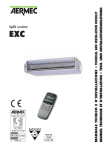
LIBRETTO ISTRUZIONI
INSTRUCTIONS MANUAL
LIVRET D’INSTRUCTIONS
GEBRAUCHSANWEISUNG
DIRETTIVE CEE 89/392 - 73/23
REV. 1/06.2002
SERIE GASTRO BUFFET “MUSIC” – DROP IN
mod. KIT RF TANGO
1400 – 2000
mod. KIT RF MAMBO
1400 – 2000
mod. KIT RF BOLERO
1400 - 2000
mod. KIT RF RUMBA
1400 - 2000
mod. KIT RF
1400 - 2000
1
PAG.
INDICE
INDEX
TABLE DES MATIERES
INHALTSVERZEICHNIS
AVVERTENZE
2
DATI DI IDENTIFICAZIONE
2
DESCRIZIONE IMPIANTO
4
DESTINAZIONE D' USO
4
TRASPORTO
4
ASSISTENZA
6
INSTALLAZIONE
6
REGOLAZIONE
6
CONSIGLI DI FUNZIONAMENTO
8
SCHEMA ELETTRICO
10-11-12
INSTALLAZIONE E MONTAGGIO
DROP IN
13
CONSIDERAZIONI GENERALI
17
ISTRUZIONI PER L’UTILIZZO
DEL TERMOSTATO DIGITALE
19
AVVERTENZE
IMPORTANT NOTES
AVERTISSEMENTS
WICHTIGE HINWEISE
-PERICOLO GENERICO
-GENERAL RISK
-DANGER GÉNÉRIQUE
-ALLGEMEINE GEFAHRENSTELLE
-LEGGERE ATTENTAMENTE
IL MANUALE DI ISTRUZIONI
-READ THE INSTRUCTIONS
MANUAL CAREFULLY
-LIRE AVEC ATTENTION LE
MANUEL D’INSTRUCTIONS
-DAS
GEBRAUCHSHANDBUCH
AUFMERKSAM LESEN
L' impianto e' stato progettato e realizzato in
ottemperanza alle Dir. CEE 73/23. Esso
risulta quindi sicuro. Inoltre l’impianto è
conforme alla direttiva CEE 89/336 sulla
compatibilità elettromagnetica.
Tuttavia indichiamo i seguenti obblighi per
l' utilizzatore:
- Non lasciare l' impianto incustodito
soprattutto in presenza di bambini.
- Non asportare le protezioni della ventola
di raffreddamento del condensatore
PERICOLO DI TAGLIO.
- Evitare di posizionare l' impianto in
prossimita' di fonti di calore (caloriferi ,
forni) o di correnti d' aria.
- Evitare l' esposizione ai raggi solari diretti
PERICOLO DI CATTIVO
FUNZIONAMENTO DELLA
REFRIGERAZIONE (CIBO AVARIATO).
- L' impianto non e' stato progettato per
essere utilizzato all' esterno, e deve essere in
ogni caso collegato a MASSA.
- Qualsiasi operazione di installazione,
manutenzione, pulizia e riparazione deve
venire eseguita in assenza di tensione
elettrica.
- Prima di utilizzare l’apparecchio
controllarne l’integrità e leggere il presente
manuale.
- Non utilizzare l’apparecchio con
alimentazione di rete fuori targa.
La targhetta di identificazione e' posta sotto
il mobile (vedi disegno).
I dati riportati sono:
- Dati indentificativi del fabbricante
- Modello dell' impianto
- Numero di serie
- Anno di costruzione
- Marchio CE di conformita'
- Classe climatica del mobile
- Dati tecnici
Per qualsiasi richiesta di intervento Vi
preghiamo di comunicare i dati contenuti
nella targhetta di identificazione.
DATI DI IDENTIFICAZIONE
ID DATA
DONNEES D'IDENTIFICATION
IDENTIFIZIERUNGSDATEN
2
PAG.
IMPORTANT NOTES
3
ID DATA
3
SYSTEM DESCRIPTION
5
PLANNED USE
5
DISPATCH
5
TECHNICAL SUPPORT
7
INSTALLATION
7
SETUP
7
OPERATING ADVICE
9
WIRING DIAGRAM
10-11-12
INSTALLATION AND ASSEMLING
DROP IN
13
GENERAL REMARKS
17
INSTRUCTIONS TO USE THE
DIGITALE THERMOSTAT
26
PAG.
AVERTISSEMENTS
3
DONNEES D'IDENTIFICATION
3
DESCRIPTION DE L'INSTALLATION
5
APPLICATION
5
TRANSPORT
5
SERVICE APRES-VENTE
7
INSTALLATION
7
REGLAGE
7
CONSEILS DE FONCTIONNEMENT
9
SCHEMA ELECTRIQUE
10-11-12
INSTALLATION ET ASSEMBLAGE
DROP IN
13
CONSIDERATIONS GENERALES
18
INSTRUCTIONS POUR L’UTILISATION
DU THERMOSTAT DIGITALE
26
SEITE
WICHTIGE HINWEISE
3
IDENTIFIZIERUNGSDATEN
3
BESCHREIBUNG DER ANLAGE
5
VERWENDUNGSZWECK
5
TRANSPORT
5
KUNDENDIENST
7
INSTALLATION
7
EINSTELLUNG
7
RATSCHLÄGE ZUM BETRIEB
9
ELEKTRISCHES SCHEMA
10-11-12
EINBAU UND MONTAGE VON
DROP IN
13
ALLGEMEINE BEMERKUNGEN
18
ANWEISUNGEN FÜR DIE VERWENDUNG
DES DIGITAL THERMOSTATS
26
The system has been designed and
manufactured in compliance with EU
directives 73/23. Therefore it is safe to
use.
The unit also complies with EU directive
89/336 on electromagnetic compatibility.
However, please note the user has to
heed the following regulations:
- Do not leave the system unattended
especially if children are present.
- Do not remove the condenser cooling
fan guards.
CUTTING HAZARD
- Do not place the system close to heat
sources (radiators, ovens) or draughts.
- Do not expose the system to direct
sunlight.
THIS MAY CAUSE IMPROPER
REFRIGERATION OPERATION
(ROTTEN FOOD)
- The system has not been designed for
outdoor use.
- Check that the electrical connection
includes an earth wire connection and
other electrical requisites according to
regulations.
- Any installation, maintenance,
cleaning or repair jobs must be
carried out with the power off.
- Before using the appliance, check that
it is undamaged and read this manual.
- Do not use the appliance at a mains
voltage higher than on the data plate.
L'installation a été projetée et réalisée
conformément aux Directives CEE 73/23
et donne donc toutes les garanties de
sécurité.
L'appareil est conforme en outre à la
Directive Cee 89/336 sur la compatibilité
électromagnétique.
Toutefois, nous énumérons ci-après les
obligations suivantes pour l'utilisateur:
- Ne pas laisser l'installation sans
surveillance, surtout en présence d'enfants.
- Ne pas enlever les protections du
ventilateur de refroidissement du
condenseur.
Die Anlage wurde gemäß der Richtlinie
73/23/EWG konzipiert und gebaut und
garantiert daher einen sicheren Betrieb.
Das Gerät entspricht außerdem den
Bestimmungen der Richtlinie 89/336/EWG
über die elektromagnetische
Verträglichkeit.
Trotzdem hat der Verwender einige
wichtige Regeln zu befolgen:
- Die Anlage nicht unbeaufsichtigt lassen,
vor allem wenn Kinder in der Nähe sind.
- Die Schutzabdeckungen des Kühllüfters
des Kondensators dürfen nicht
abgenommen werden.
SCHNEIDEGEFAHR.
- Die Anlage darf nicht in der Nähe von
Wärmequellen (Heizkörper, Öfen) oder
Zugluft aufgestellt werden.
- Die Anlage darf keinen direkten
Sonnenstrahlen ausgesetzt werden.
GEFAHR DES SCHLECHTEN
KÜHLBETRIEBS (VERDORBENE
SPEISEN).
- Die Anlage wurde nicht für die
Benutzung
im
Außen
konzipiert.
Überprüfen Sie, ob die elektrische
Spannung nicht nur mir Erdung versehen
ist, sondern auch ob die weiteren
Bestimmungen und Normen bezüglich der
elektrischen Anlagen befolgen sind.
- Vor jedem Installations-, Wartungs- ,
Reinigungs -und Reparatureingriff muß
die Stromzufuhr unterbrochen werden.
- Vor der Verwendung die Unversehrtheit
des Geräts prüfen und dieses Handbuch
lesen.
- Das Gerät nicht verwenden, falls die
Netzspannung auf dem Typenschild mit
der örtlicher Netzspannung nicht
übereinstimmt.
The serial plate is located under the unit
(see drawing):
The following data is specified:
- Manufacturer's identification data
- System model
- Serial number
- Year of manufacture
- EU compliance mark
- Climatic class
- Specifications
For any servicing requests, please advise
us of the data specified on the serial
plate.
La plaquette d'identification est située au
dessous du meuble (voir dessin).
Les données indiquées sont:
- Identification du constructeur
- Modèle de l'installation
- Numéro de série
- Année de construction
- Label CE de conformité
- Classe climatique
- Caractéristiques techniques
Pour toute demande d'intervention, nous
vous prions de communiquer les données
contenues dans la plaquette d'identification.
RISQUE DE COUPURE.
- Eviter de positionner l'installation à
proximité de sources de chaleur (radiateurs,
fours ou courants d'air).
- Eviter l'exposition directe aux rayons
solaires.
RISQUE DE MAUVAIS
FONCTIONNEMENT DE LA
REFRIGERATION (ALIMENTS
AVARIES)
- L'installation n'a pas été projetée pour être
utilisée à l'extérieur.
- Vérifier que la connexion électrique soit
non seulement munie de mise a la terre
mais qu’elle correspond aussi aux autres
dispositions et réglementations relatives
aux
installations
électriques
de
l’alimentation.
- Toutes les opérations d'installation,
d'entretien, de nettoyage et de
réparation doivent être exécutées après
avoir interrompu l'alimentation
électrique.
- Avant l’utilisation de l’ appareil, il faut
contrôler son integrité et lire ce manuel
d’instructions.
- Ne pas utiliser l’appareil si la tension
indiquée sur la plaque signaletique ne
correspond pas au secteur local.
3
Das Typenschild befindet sich unter dem
Gerät (siehe Zeichnung).
Darauf sind folgende Daten angegeben:
- Identifizierungsdaten des Herstellers
- Modell der Anlage
- Seriennummer
- Baujahr
- CE-Konformitätszeichen
- Klimaklasse
- Technische Daten
Bei jeder Anforderung von Reparaturbzw. Wartungseingriffen bitten wir Sie um
Angabe der auf dem Typenschild
aufgeführten Daten.
DESCRIZIONE DELL' IMPIANTO
SYSTEM DESCRIPTION
DESCRIPTION DE L'INSTALLATION
BESCHREIBUNG DER ANLAGE
1
2
4
5
3
DESTINAZIONE D' USO
PLANNED USE
APPLICATION
VERWENDUNGSZWECK
-PERICOLO GENERICO
-GENERAL RISK
-DANGER GÉNÉRIQUE
-ALLGEMEINE GEFAHRENSTELLE
-LEGGERE ATTENTAMENTE
IL MANUALE DI ISTRUZIONI
-READ THE INSTRUCTIONS
MANUAL CAREFULLY
-LIRE AVEC ATTENTION LE
MANUEL D’INSTRUCTIONS
-DAS GEBRAUCHSHANDBUCH
AUFMERKSAM LESEN
TRASPORTO
DISPATCH
TRANSPORT
TRANSPORT
Gli impianti di ristorazione refrigerati
sono cosi' strutturati:
- Struttura del mobile e della base in
lamiera di acciaio
- Vasca interna in inox isolata con resine
poliuretaniche espanse
- Calotta superiore in vetro o in plexiglas
manufatta, completa di illuminazione
interna.(1-2-3-4)
- Apertura manuale della calotta.(1-2-3)
- Sovrastruttura fissa in vetro (4)
- Refrigerazione di tipo statico con
condensatore ventilato con evaporatore
in serpentina di rame messa a spirale
sulle pareti perimetrali della vasca
- Scarico sul fondo vasca per scarico
acqua di condensazione
- Unita' condensatrice del tipo ermetico e
condensazione
ad
aria
con
termoregolatore elettronico per il
controllo automatico della temperatura
- Interruttore sul termoregolatore per
lampada di illuminazione.(1-2-3-4)
Gli impianti di ristorazione sono stati
previsti per l' esposizione e la
momentanea conservazione di alimenti
destinati all' immediato consumo o
vendita nei pubblici esercizi quali:
Ristoranti, Alberghi, Trattorie, Pizzerie,
Gastronomie e a titolo promozionale nei
Supermercati.
NESSUN ALTRO USO E'
CONSENTITO.
La ENOFRIGO S.r.l. e' sollevata da ogni
responsabilita' nel caso che le unita' da lei
prodotte non venissero utilizzate per gli
usi previsti.
L' impianto imballato e posto su pallet
viene caricato con l' ausilio di un carrello
elevatore e collocato all' interno dell'
automezzo, o vagone o container, fissato
con appositi fermi meccanici e protetto ai
lati da materiale antiurto.
L'ENOFRIGO non risponde dei danni
provocati da operazioni mal eseguite.
1-2
4
The refrigerated catering counters are
made up as follows:
Counter frame and bottom made of
stainless steel
Stainless steel internal body insulated
with polyurethane foam
- Top hood made of manufactured
plexiglass with internal lighting.(1-2-3-4)
Open / close canopy moving with
manual mechanism.(1-2-3)
Top hood made of glass (4)
- Static refrigeration with ventilated copper
spiral evaporator on the outer walls of the
body
- Drain outlet at the bottom of the body to
drain off condensate
- Watertight air condenser unit with
thermostat for automatic temperature
control
- Separate switch for the lighting lamp.(12-3-4)
Les installations de restauration réfrigérées
sont structurées de la façon suivante:
- Structure du meuble et de la base en acier
- Cuve interne en inox isolée avec résines
polyuréthannes expansées
- Coupole supérieure en plexiglas galbée,
avec éclairage interne.(1-2-3-4)
- Actionnement "ouvre et ferme" raccordé
à un mécanisme manuel.(1-2-3)
- Coupole supérieure en glass (4)
- Réfrigération de type statique avec
condenseur ventilé avec évaporateur à
serpentin en cuivre disposé en spirale sur
les parois périmétrales de la cuve
- Purge sur le fond de la cuve pour le
vidage de l’eau de condensation
- Unité de condensation de type hermétique
et condensation par air avec thermostat
pour le contrôle automatique de la
température
- Interrupteur séparé pour lampe éclairage.
(1-2-3-4)
Die Kühlanlage für die Gastronomie sind
folgendermaßen aufgebaut:
- Möbelstruktur und Unterbau aus Stahl
- Innere Wanne aus Inox-stahl, isoliert
mit Purharzen
- Obere handgefertigte Haube aus
Plexiglass
komplett
mit
Innenbeleuchtung.
(1-2-3-4)
Öffnungsund
Schließsystem
verbunden
mit
einem manuellen
Mechanismus.(1-2-3)
- Obere handgefertigte Haube aus Glass
(4)
- Statische Kühlung mit belüftetem
Kondensator mit Verdampfer aus
Kupfer-schlangenrohr,
das
spiralförmig um die Wände der Wanne
läuft
- Ablaßhahn am Wannenboden zum
Entleeren des Kondenswassers
- Hermetische Kondensatoreinheit und
Luftkondensation mit Thermostat für
die automatische Temperaturkontrolle
- Separater Schalter für die Beleuchtung.
(1-2-3-4)
The refrigerated catering counters are
designed for display and temporary cold
storage of foods served for immediate
eating or on sale to the public in
Restaurants, Hotels, Cafeterias, Pizzerias,
Buffets and for Supermarket promotion.
NO OTHER USE IS AUTHORIZED
ENOFRIGO S.r.l does not bear any
liability if the unit you purchased is not
used for its planned purposes.
Les installations de restauration réfrigérées
ont été prévues pour l'exposition et la
conservation
momentanée
d'aliments
destinés à la consommation immédiate ou à
la vente dans les établissements publics tels
que: Restaurants, Hôtels, Pizzerias,
Traiteurs et à titre promotionnel dans les
Supermarchés
AUCUNE AUTRE UTILISATION N'EST
AUTORISEE
ENOFRIGO
S.r.l.
décline
toute
responsabilité dans le cas où les appareils
de sa production sont destinés à des
utilisations différentes par rapport aux
celles qui sont prévues dans cet opuscule.
Die Kühlanlage für die Gastronomie
dienen
zur
Ausstellung
und
vorübergehenden Konservierung von
Nahrungsmitteln, die für den baldigen
Verzehr bzw. Verkauf in Restaurants,
Hotels,
Gaststätten,
Pizzerias,
Delikatessengeschäften, sowie während
bestimmter
Werbeaktionen
in
Supermärkten, bestimmt sind.
ANDERE VERWENDUNGEN SIND
NICHT ZULÄSSIG.
Falls die von ihr gebauten Geräte nicht
für die vorgesehenen Zwecke verwendet
werden, ist die Fa. ENOFRIGO S.r.l. von
jeder Verantwortung befreit.
The packaged and palletized system is
loaded with a forklift truck and placed in a
truck, railcar or container, secured with
special mechanical clamps and protected
on the sides by shockproof material.
ENOFRIGO is not liable for any damage
caused by ill-performed jobs.
L'installation emballée et mise sur palette
est chargée à l'aide d'un chariot élévateur et
placée à l'intérieur du camion, wagon ou
container, bloquée avec des dispositifs
mécaniques et protégée sur les côtés par
des matériaux antichoc.
Une fois parvenue à destination, elle doit
être déchargée de la même manière, c'est-àdire à l'aide d'un chariot élévateur et posée
par terre en prenant toutes les précautions
nécessaires.
ENOFRIGO ne répond pas des dommages
provoqués par des opérations effectuées de
manière incorrecte.
Die verpackte und auf eine Palette
gestellte Anlage wird mit Hilfe eines
Hubkarrens geladen, in den Lieferwagen
bzw. Güterwagon oder Container
gestellt,
mit
dafür
vorgesehenen
mechanischen
Feststellvorrichtungen
blockiert
und
seitlich
mit
stoßdämpfendem Material geschützt.
Die Fa. ENOFRIGO haftet nicht für
Schaden, die durch unsachgemäßes
Wirken verursacht wurden.
5
Consigliamo di rivolgerVi direttamente alla
nostra azienda o ai nostri rivenditori autorizzati
che provvederanno alla migliore e razionale
escuzione di qualsiasi lavoro di revisione e
riparazione mediante personale specializzato e
con attrezzature appositamente studiate per tale
esercizio.
ASSISTENZA
TECHNICAL SUPPORT
SERVICE APRES-VENTE
KUNDENDIENST
Sballare accuratamente l' impianto togliendo il
cartone principale.
Togliere tutti i materiali protettivi
dall’ imballo.
Posizionare l’impianto in adeguato sito rispettando le
norme tecnico-sanitarie e per quanto riguarda
l’alimentazione elettrica rispettando le norme del
proprio Paese.
Verificare che la tensione e la frequenza elettrica
disponibile sia la stessa riportata nella targhetta di
identificazione.
Verificare
prima
dell’installazione
l’integrità
dell’apparecchio.
Dopo aver pulito e posizionato l’apparecchio
verificare i dati delle sue caratteristiche ed usare una
presa idonea.
E’ obbligatorio avere a monte un differenziale
idoneo (vedere targhetta identificatrice). E’
consigliabile che tale operazione sia svolta da un
esperto elettricista.
I materiali impiegati per l’imballo devono essere
smaltiti secondo le leggi vigenti del Paese di utilizzo.
AVVERTENZA:
Il cavo e la spina di aliemntazione devono risultare
facilmente accessibili dopo l’installazione. Qualora
evidenziassero segni di usura devono essere
immediatamente sostituite.
INSTALLAZIONE
INSTALLATION
INSTALLATION
INSTALLATION
Azionando l’interruttore circolare si alimenta
l’impianto elettrico del mobile. Per far funzionare
il mobile sollevare lo sportellino trasparente dello
strumento di controllo e premere il pulsante di
accensione. Sullo strumento di controllo è presente
anche il pulsante per l’accensione e lo
spegnimento delle luci. Il pulsante per le luci è
riconoscibile dal segno grafico della lampadina. Il
termostato elettronico consente la regolazione
della temperatura (Set Point) fra 0°C e +10°C. La
temperatura preimpostata è di +2°C.
Il funzionamento del termostato elettronico è
descritto in dettaglio nel manualetto allegato.
Viene
effettuato
automaticamente
uno
sbrinamento della durata di 120’ ogni 12 ore. E’
tuttavia necessario, ogni due giorni o anche più
spesso, operando in condizioni ambientali
particolari, effettuare uno sbrinamento “manuale”.
Lo sbrinamento manuale va effettuato svuotando
completamente il mobile dalle vaschette dei
prodotti alimentari e spegnendo l’interruttore
generale fino a completo scioglimento del ghiaccio
accumulatosi. L’acqua va quindi evacuata e la
vasca asciugata.
Le migliori prestazioni dell’impianto si hanno con
temperatura ambiente di 25° C e con umidita'
relativa U.R. 60% (classe climatica 3 secondo EN
441).
Prima dell' uso e del collegamento elettrico pulire t
le parti con acqua tiepida e saponi neutri sanificanti
asciugare accuratamente.
REGOLAZIONE
SETUP
REGLAGE
EINSTELLUNG
Termoregolatore
Thermoregulator
Thermoregulateur
Wärmeregler
Interruttore generale
Main switch
Interrupteur general
Hauptschalter
Non usare in nessun caso polveri abrasive o
detersivi che potrebbero danneggiare l' impianto
sia internamente che esternamente specialmente
nelle parti in vetro o plexiglas.
6
We suggest you directly to contact our company or
our authorized dealers who will arrange to have any
servicing and repair jobs carried out by skilled
personnel using tools specially designed for these
operations.
Nous vous conseillons de vous adresser
directement à notre société ou à nos revendeurs
agréés qui viendront effectuer, de la manière la
plus fiable et rationnelle, tous les travaux de
révision et de réparation avec du personnel
spécialisé et des équipements spéciaux étudiés
pour ce service.
Am besten wenden Sie sich direkt an uns oder
an unsere Vertragshändler, die für die
einwandfreie Ausführung jeder Überholung
bzw. Reparatur durch Fachpersonal und mit
Spezialwerkzeug sorgen werden.
Carefully unpack the system removing the main
cardboard.
Take off protective packaging materials from all
components of the system and lastly remove the
wooden pallet underneath.
Position the appliance in a suitable site, respecting
the technical and health standards and the
regulations in force in your own country concerning
electric power supply.
Check that the electrical voltage and frequency
available are the same as those indicated on the
serial plate.
Before installation, check that the appliance is
undamaged.
After having cleaned the appliance and put it into
position, insert the cable provided in the embedded
socket in the base, check the technical data and use a
suitable wall socket. It is necessary to have a
suitable differential switch upstream (see data
plate ). This operation should be carried out by a
skilled electrician. The packing materials used must
be disposed of in accordance with the laws in force
in your Country.
IMPORTANT:
The power supply cable and the plug must be easly
accessible after the installation. If they should ever
show of wear and tear, they must be replaced
immediately.
Déballer soigneusement l'installation en enlevant
le carton principal.
Positionner l’appareil dans un endroit adéquat en
observant les règles techniques et sanitaires et
pour ce qui concerne l’alimentation électrique en
respectant les normes en vigueur dans Votre
Pays.
Vérifier que la tension et la fréquence électrique
disponible correspondent aux données figurant
sur la plaquette d'identification.
Avant l’installation, vérifier l’intégrité de
l’appareil. Après avoir nettoyé et mis en place
l’appareil, enforcer le cable dont il est equipé
dans la prise encastrée
sur la base,controler les données des
caractéristiques de l’appareil et utiliser une prise
edéquate. Il est nécessaire d’avoir un
différentiel approprié (voir la plaque
d’identification ). Il est conseillable aussi que
cette opération soit effectuée par un électricien
expérimenté. Les matériaux employés pour
l’emballage doivent être mis à la décharge selon
les normes en vigueur dans Votre Pays.
AVVERTISSEMENT:
Le cable et la fiche d’alimentation doivent être
accessibles facilement après l’installation. Si l’on
remarque des signes d’usure, il faut les remplacer
immédiatement.
Die Anlage sorgfältig aus dem Hauptkarton
auspacken.
Die Schutzverpackung aller Komponenten der
Anlage entfernen und zuletzt die Holzpalette
am Unterbau entfernen.
Das Gerät auf einem angemessenen Ort
aufstellen, um die technischen und sanitären
Vorschriften ebenso wie die
Spannungsbestimmungen des Landes zu
beachten. Vor Aufstellung die Unversehrtheit
des Geräts kontrollieren. Nach der Reinigung
und Aufstellung des Geräts, das ausgestattene
Kabel auf dem Abgreifpunkt der Grundlage
stecken, die Kenndaten des Geräts prüfen und
einen passenden Stecker anwenden. Es ist
notwendig, ein geeignete Differential zu
haben (siehe die Identifizierungsschild). Es
wird empfholen, diesen Arbeitsgang durch
technisches Fachpersonal auszuführen.Vor der
Verwendung sicherstellen, daß die Räder
durch die zweckmäßigen Sperrungen blockiert
werden. Die Verpackungsteile sind nach
diesbezüglich geltenden Vorschriften des
Landes zu beseitigen.
WICHTIGE HINWEISE:
Das Kabel und der Speisungsstecker müssen
leicht zugänglich nach der Anlage sein. Falls
man Verschleißzeichen bemerkt, ist es
notwendig sie auszuwechseln.
To turn on the electric system press the round switch
(main switch).
To turn on the unit lift the plexiglass cover of the
control instrument and press the starting button.
The control instrument includes the lighting switch.
The lighting switch is marked by a lamp draining.
The electronic thermostat enables to control the
temperature (Set Point) between 0°C and +10°C.
The preset temperature is set at +2°C. The function
of the electronic thermostat is described in detail in
the manual supplied. Defrosting is carried out
automatically for the duration of 120 minutes every
12 hours. It is however necessary every two days, or
even more often when the unit operates in particular
conditions to manually defrost. Manual defrosting is
carried out by emptying the food containers and
switching off the main switch until all the
accumulated ice is melted. The water is then
removed and the container dried.
The best performance of the until is achieved with
the ambient temperature of 25 °C and with the
relative humidity of 60% (climatic class 3 according
to EN441 standard).
Do not, under any circumstances, use abrasive or
cleansing powder as they might damage both the
inside and outside of the system, especially glass
and plexiglass parts.
On active l’installation èlectrique du meuble en
actionnant l’interrupteur gènèral rond.
Soulever le couvercle en plexi de l’instrument de
contrôle et appuyer le bouton de l’allumoge
frigorifique.
L’instrument de contrôle comprend aussi le
bouton pour l’èclairage.
Le bouton de l’èclairage est marquè par le dessin
d’une ampoule. Le thermostat életronique permet
le réglage de la température (Set Point) entre 0°C
et +10°C. La température préintroduite est
+2°C. Le fonctionnement du themostat
électronique est décrit en detail dans le livret
joint. Un dégivrage de 120’ toutes les 12 heures
est réalisé automatiquement. Il est cependant
nécessaire d’exécuter – en condition ambiente
particuliére – un dégivrage “manuel” tous les
deux jours ou même plus souvent. On réalise le
dégivrage manuel en vidant entièrement le
meuble des récipiént des produits alimentaires et
en éteindant l’interrupteur général jusqu’à la
fonte complète de la glace accumulée. On doit
ensuite évacuer l’eau et essuyer la cuve.
Les meilleures performances de l’installation
s’obtiennent avec une température ambiente de
25°C et une humidité relative H R de 60% (class
climatique 3 selon EN441).
Avant l'utilisation et le branchement électrique,
nettoyer toutes les parties avec de l'eau tiède et
des savons neutres puis essuyer soigneusement.
N'utiliser en aucun cas des poudres abrasives ou
des détergents qui pourraient endommager
l'installation tant à l'intérieur qu'à l'extérieur, en
particulier sur les parties en verre ou en
plexiglass.
Wenn man roten Kreisförmigen Schalter
antreibt, Kann man elektrische Anlage vom
Möbel speisen. Man muß durchsichtiges
Fenster vom Kontrollgerät hochziehen und der
Startknopf drücken, unu das Möbel in
Bewegung zu setzen.
Auf Kontrollgerät stehen auch Startknopf und
Ausschaltung der. Beleuchtung und den knopf
vom Ventilator für anlauffrei der kalotte. Der
elektrische Thermostat erlaubt die
Temperaturregelung (Set Point) zwischen 0°C
und +10°. Die voreingestellte Temperatur ist
+2°C. Die ausführlichen Betriebsanweisungen
des elektronischen Thermostats sind auf dem
beiliegenden Handbuch beschrieben..
Eine Abtauung von 120‘ Dauer je 12 Stunden
wird automatisch ausgeführt, trotzdem ist eine
“manuelle“ Abtauung jeden zweiten Tag oder
auch öfter – bei Sonderumweltbedingungen –
notwendig. Die manuelle Abtauung wird durch
komplette Entleerung des Möbels von den
Nahrungsmittel-Gefäßen und durch die
Abschaltung des Hauptschalters bis zur
völlstandigen Eisschmelze ausgeführt. Das
Wasser wird dann geraümt und das Becken
wird trockengerieben.
Die besten Leistungen der Anlage werden bei
25°C Raumtemperatur und relative
Feuchtigkeit (rF) von 60% (klimatische Klasse
3 nach EN441) erzielt.
Vor Gebrauch und Stromanschluß müssen alle
Teile mit Warmwasser und neutralen Seifen
gesäubert, und danach gut getrocknet werden.
Verwenden Sie unter keinen Umständen
Scheuerpulver oder Reinigungsmittel, die die
Anlage sowohl innen als auch außen, und
insbesondere die Teile aus Glas oder Plexiglas
beschädigen könnten.
7
CONSIGLI DI FUNZIONAMENTO
OPERATING ADVICE
CONSEILS DE FONCTIONNEMENT
RATSCHLÄGE ZUM BETRIEB
-PERICOLO GENERICO
-GENERAL RISK
-DANGER GÉNÉRIQUE
-ALLGEMEINE GEFAHRENSTELLE
-LEGGERE ATTENTAMENTE
IL MANUALE DI ISTRUZIONI
-READ THE INSTRUCTIONS
MANUAL CAREFULLY
-LIRE AVEC ATTENTION LE
MANUEL D’INSTRUCTIONS
-DAS
GEBRAUCHSHANDBUCH
AUFMERKSAM LESEN
8
Accendere
l'illuminazione
solamente
durante il servizio vero e proprio.
In caso di intasamento eccessivo di
ghiaccio sulle pareti della vasca, disinserire
l’impianto.
Attendere quindi che il ghiaccio si sia
completamente sciolto, scaricare l'acqua
che si sara' formata nella vasca e quindi
rimettere in funzione l' impianto.
E' importantissimo pulire con una spazzola
o aspirapolvere almeno ogni 15 giorni il
condensatore.
Consigliamo di mettere i prodotti
alimentari (per quanto sia possibile) gia'
refrigerati.
Gli interventi devono essere eseguiti in
assenza di alimentazione elettrica.
Switch on lighting only when actually
serving food.
If the body walls are excessively clogged
with ice, switch off the system power.
Then wait for the ice to melt completely,
drain off the water formed in the body, and
then restart the system.
It is very important to clean the condenser
with a brush or vacuum cleaner every
fortnight.
We suggest, if possible, you to place precooled food products in the refrigerated
counter.
Maintenance work must be carried out
with the power off.
Allumer la lumière seulement durant le
service proprement dit.
En cas de formation excessive de glace sur
les parois de la cuve, débrancher
l'installation.
Attendre que la glace ait complètement
fondu, vider l'eau recueillie au fond de la
cuve, puis remettre l'installation en
marche.
Il est très important de nettoyer le
condenseur avec une brosse ou un
aspirateur au moins tous les 15 jours.
Nous conseillons de mettre les aliments
(dans la mesure du possible) déjà
réfrigérés.
Les interventions sur l'installations
doivent être faites en l'absence
d'alimentation électrique.
9
Nur während der eigentlichen Bedienung
die Haube anheben und die Beleuchtung
einschalten.
Wenn die Wände der Wanne übermäßig
vereist sind, die Stromzufuhr zur Anlage
unterbrechen.
Abwarten, bis das Eis vollkommen
geschmolzen ist, dann das Wasser, das
sich in der Wanne angesammelt hat, mit
dem dafür vorgesehenen Ablaßhahn
entleeren, und die Anlage wieder in
Betrieb setzen.
Mindestens alle 15 Tage mit einer kleinen
Bürste oder mit einem Staubsauger
gesäubert werden.
Es empfiehlt sich (soweit möglich) bereits
gekühlte Lebensmittel in die Kühlanlage
zu stellen.
Reparatur- bzw. Wartungseingriffe
dürfen erst durchgeführt werden,
nachdem die Stromzufuhr unterbrochen
wurde.
10
11
12
13
14
15
CONSIDERAZIONI GENERALI
GENERAL REMARKS
16
INCONVENIENTI
Se l’unità refrigerata non funziona:
PROBLEMS
If the refrigerate unit does not work:
- verificare corretto allacciamento
- verificare se inserita la tensione
- verificare la taratura del termostato
Se dopo aver eseguito tali verifiche l’inconveniente persiste
richiedere l’assistenza di un tecnico specializzato.
- check that the appliance is correctly connected
- check that the appliance is live
- check the thermostat setting
If the problem persists after you have checked what we say
above, ask for the assistance of a skilled technician.
MANUTENZIONE
Ogni fine giornata, o turno di lavoro, dopo aver disinserito la
fonte di energia attendere che l’impianto si sia raffreddato. Prima
dell' uso e del collegamento elettrico pulire tutte le parti con
acqua tiepida e saponi neutri sanificanti, poi asciugare
accuratamente.
Non usare in nessun caso polveri abrasive o detersivi che
potrebbero danneggiare l' impianto sia internamente che
esternamente specialmente nelle parti in vetro o plexiglas.
Verificare sempre che il cavo di alimentazione sia integro ed
eventualmente sostituirlo.
MAINTENANCE
At the end of each day, or of each shift, after having
disconnected the power supply wait for the appliance to cool
down. Do not, under any circumstances, use abrasive or
cleansing powder as they might damage both the inside and
outside of the system, especially glass and plexiglass parts.
Always check that the power cable is unbroken and change it if
necessary.
INATTIVITA’
In caso di inattività prolungata dell’apparecchio si deve
procedere nel modo seguente:
INACTIVITY
In the case of prolunged inactivity of the appliance, proceed as
follows:
- staccare la fonte di energia
- pulire accuratamente l’apparecchio con prodotti disinfettanti
- proteggere l’apparecchio dall’ossidazione con prodotti neutri
- coprire onde evitare il deposito di polvere.
- disconnect the power supply
- clean the appliance accurately with disinfectants
- use neutral products to protect the appliance against oxidation
- cover it to stop it gathering dust.
DEMOLIZIONE
Alla fine della sua vita, l’apparecchio si deve smaltire secondo le
leggi vigenti del Paese di utilizzo.
DEMOLITION
At the end of its working life, the appliance must be disposed of
in accordance with the laws in force in the country of use.
CARATTERISTICHE TECNICHE
TECHNICAL CHARACTERISTICS
Tensione:
Voltage:
220-240 Volt 1ph+T
Potenza
Kit Rf 1400: 435 W
Kit Rf 2000: 464 W
Kit Rf (Tango-Mambo-Bolero-Rumba) 1400:
Kit Rf (Tango-Mambo-Bolero-Rumba) 2000:
471 W
522 W
220-240 Volt 1ph+Earth
Power
Kit Rf 1400: 435 W
Kit Rf 2000: 464 W
Kit Rf (Tango-Mambo-Bolero-Rumba) 1400:
Kit Rf (Tango-Mambo-Bolero-Rumba) 2000:
471 W
522 W
Lampada fluorescente
Kit Rf (Tango-Mambo-Bolero-Rumba) 1400: L 36W/41-827;
tensione 220-240 V
Kit Rf (Tango-Bolero-Rumba) 2000: L 58W/41-827; tensione
220-240 V
Kit Rf (Mambo) 2000: L 2x30W; tensione 220-240 V
GARANZIA
Fluorescent lamp
Kit Rf (Tango-Mambo-Bolero-Rumba) 1400: L 36W/41-827;
Voltage 220-240 V
Kit Rf (Tango-Bolero-Rumba) 2000: L 58W/41-827; Voltage
220-240 V
Kit Rf (Mambo) 2000: L 2x30W; Voltage 220-240 V
GUARANTEE
Modalità e durata: un anno tranne materiale elettrico.
Foro competente: foro di Padova. . Restano esclusi dalla garanzia
le parti elettriche ed elettroniche e quei componenti dei Prodotti
che per natura o destinazione sono soggetti a deterioramento o
logorio. L’Acquirente decadrà dalla garanzia se utilizzerà i
Prodotti in modo non conforme alle istruzioni del Venditore;
l’Acquirente decadrà altresì dalla garanzia se provvederà
autonomamente, e così senza l’autorizzazione e/o il controllo del
Venditore a smontare, modificare tentare di riparare i Prodotti.
Terms and duration: one year, except electrical material.
Competent court: court of Padua. In the warranty electrical and
electronic parts as well as those elements that normally wear
out are excluded. The warranty will be not valid any longer if
the buyer uses the products in a different way from the seller’s
instructions, the warranty will be not valid as wellif the buyer
by him self and without the permission and the control of the
seller dissambles, modifies and tries to repair the products.
La ENOFRIGO srl si riserva di apportare modifiche alla ENOFRIGO srl claims the right to introduce changes in
manifacturing process and units equipment without
costruzione ed alla dotazione dei mobili senza alcun
prior notice.
obbligo di preavviso.
17
CONSIDÉRATIONS GÉNÉRALES
ALLGEMEINE BEMERKUNGEN
INCONVÉNIENTS
Si l’unité de réfrigération ne marche pas:
UNANNEHMLICHKEITEN
Falls die Anlage nicht läuft:
- vérifier si la connexion est correcte
- vérifier si la tension est branchée
- vérifier le calibrage du thermostat
Si après avoir effectué ces contrôles l’inconvénient persiste, il
faut requérir l’assistence d’un technicien spécialisé.
- prüfen Sie den richtigen Anschluss;
- prüfen Sie die Anschluss - spannung;
- prüfen Sie die Eichung des Thermostats.
Falls die Unannehmlichkeit nach dieser Kontrolle andauert, sich
an einen technischen Fachpersonal wenden.
ENTRETIEN
A la fin de chaque journée ou d’un travail par roulement, après
avoir coupé la source d’énergie et attendu que l’installation se
soit refroidie. Avant l'utilisation et le branchement électrique,
nettoyer toutes les parties avec de l'eau tiède et des savons
neutres puis essuyer soigneusement.
N'utiliser en aucun cas des poudres abrasives ou des détergents
qui pourraient endommager l'installation tant à l'intérieur qu'à
l'extérieur, en particulier sur les parties en verre ou en
plexiglass.Vérifier toujours que le câble de l’alimentation soit
intact et éventuellement vous pouvez le remplacer.
WARTUNG
Bei täglichem Arbeitsende oder Arbeitsschicht die
Elektrizitätsquelle ausschalten und die Kühlung der Anlage
erwarten. Vor Gebrauch und Stromanschluß müssen alle Teile
mit Warmwasser und neutralen Seifen gesäubert, und danach
gut getrocknet werden.Verwenden Sie unter keinen Umständen
Scheuerpulver oder Reinigungsmittel, die die Anlage sowohl
innen als auch außen, und insbesondere die Teile aus Glas oder
Plexiglas beschädigen könnten. Die Integrität des Speisekabels
immer prüfen, falls es rißig ist, sollte es gewechselt werden.
INACTIVITÉ
Pedant des périodes d’inactivité prolongée de l’appareil, il faut
procéder dans la façon suivante:
- débrancher la source d’énergie
- nettoyer soigneusement l’appareil en utilisant des produits
désinfectants
- protéger l’appareil de l’oxydation avec des produits neutres
- couvrir l’appareil afin d’éviter le dépôs de poussière.
DÉMANTELEMENT
A la fin de son activité, on doit mettre à la décharge l’appareil
selon les normes en vigueur dans le Pays où il a été utilisé.
UNTÄTIGKEIT
Bei verlängerter Untätigkeit des Geräts auf folgende Weise
vornehmen:
- die Energiequelle ausschalten
- das Gerät mit Desinfektionsmittel sorgfältig reinigen
- das Gerät mit neutralen Produkten vor der Oxydation schützen
- das Gerät bedecken, um den Staub zu vermeiden.
VERSCHROTTUNG
Falls man das Gerät abbrechen will, muß man es zu den
vorgesehenen Sammelstellen nach den geltenden Bestimmungen
des Landes bringen.
TECHNISCHE DATEN
CARACTERISTIQUES TECHNIQUES
Spannung:
Tension:
220-240 Volt 1ph+T
220-240 Volt 1ph+T
Puissance:
Kit Rf 1400: 435 W
Kit Rf 2000: 464 W
Kit Rf (Tango-Mambo-Bolero-Rumba) 1400:
Kit Rf (Tango-Mambo-Bolero-Rumba) 2000:
471 W
522 W
Avec lampe fluorescente (tube)
Kit Rf (Tango-Mambo-Bolero-Rumba) 1400: L 36W/41-827;
Tension 220-240 V
Kit Rf (Tango-Bolero-Rumba) 2000: L 58W/41-827; Tension
220-240 V
Kit Rf (Mambo) 2000: L 2x30W; Tension 220-240 V
GARANTIE
Modalité et durée: une année, sauf le matériau électrique.
Tribunal compétent: Tribunal de Padoue. La garantie ne
comprend pas les parties èlectriques et èlectroniques aussi bien
que les èlèments qui s’abiment normalement. La garantie n’est
pas valide si l’acheteur utilise les produits de façon différente par
rapport aux instrutions données par le vendeur. La garantie n’est
pas valide aussi si l’acheteur deémonte, modifie et répare les
produits tout seul et sans l’autorisationet le controle du vendeur.
ENOFRIGO srl se réserve le droit d’ apporter toutes
modifications utiles sans préavise.
Leistung:
Kit Rf 1400: 435 W
Kit Rf 2000: 464 W
Kit Rf (Tango-Mambo-Bolero-Rumba) 1400:
Kit Rf (Tango-Mambo-Bolero-Rumba) 2000:
471 W
522 W
Mit Leuchstofflampe (rohr)
Kit Rf (Tango-Mambo-Bolero-Rumba) 1400: L 36W/41-827;
Spannung 220-240 V
Kit Rf (Tango-Bolero-Rumba) 2000: L 58W/41-827; Spannung
220-240 V
Kit Rf (Mambo) 2000: L 2x30W; Spannung 220-240 V
GARANTIE
Bedingungen und Dauer: ein Jahr außer dem elektrischen
Material.
Züstandiges Gericht: Gericht von Padua. Von der Garantie sind
die elektrischen und elektronischen Teile und jene Elemente
ausgeschlossen, die sich normalerweise abnutzen. Die Garantie
wird nicht mehr gultig, wenn der Kaufer die Produkte nicht
gemass der Anweisungen des Verkaufers verwendet. Die
Garantie wird ebensoviel ungultig, wenn der Kaufer selbst, d.h.
ohne die Ermachtigung und/oder die Uberprufung des
Verkaufers, die Produkte abmontiert, andert und repariert.
ENOFRIGO srl behältet sich mögliche Änderungen an
Bauweise und Ausstattung der Modellen ohne vorherige
Mitteilung vor.
18
WING
XW230L
1.Avvertenze generali
1.1
Da leggere prima di procedere ulteriormente nell’utilizzo del manuale.
• Il presente manuale costituisce parte integrante del prodotto e deve essere conservato presso l’apparecchio per una facile e
rapida consultazione.
• Il regolatore non deve essere usato con funzioni diverse da quelle di seguito descritte, in particolare non può essere usato
come dispositivo di sicurezza.
• Prima di procedere verificare i limiti di applicazione.
1.2
Precauzioni di sicurezza
• Prima di connettere lo strumento verificare che la tensione di alimentazione sia quella richiesta.
• Non esporre l’unità all’acqua o all’umidità: impiegare il regolatore solo nei limiti di funzionamento previsti evitando cambi
repentini di temperatura uniti ad alta umidità atmosferica per evitare il formarsi di condensa.
• Attenzione: prima di iniziare qualsiasi manutenzione disinserire i collegamenti elettrici dello strumento.
• Lo strumento non deve mai essere aperto.
• In caso di malfunzionamento o guasto, rispedire lo strumento al rivenditore o alla “DIXELL s.r.l.” (vedi indirizzo) con una
precisa descrizione del guasto.
• Tenere conto della corrente massima applicabile a ciascun relè (vedi Dati Tecnici).
• Piazzare la sonda in modo che non sia raggiungibile dall’utilizzatore finale.
• Fare in modo che i cavi delle sonde, della alimentazione del regolatore della alimentazione dei carichi rimangano separati e
sufficientemente distanti fra di loro, senza incrociarsi e senza formare spirali.
• Nel caso di applicazioni in ambienti industriali particolarmente critici, può essere utile inoltre adottare filtri di rete (ns.
mod. FT1) in parallelo ai carichi induttivi.
2.Descrizione generale
L’XW230L è un controllore a microprocessore, formato 38x185, adatto per applicazioni su unità refrigeranti a temperatura
normale. Dispone di quattro uscite a relè per il controllo del compressore, luce, allarme e uscita ausiliaria. E’ dotato di due
ingressi sonda NTC, uno per la termostatazione, l’altro facoltativo per la visualizzazione a display. Sono presenti inoltre due
ingressi digitali (contatti puliti), uno per il microporta e l’altro configurabile da parametro. L’uscita TTL permette il
collegamento attraverso un modulo esterno a sistemi di monitoraggio ModBUS-RTU compatibili e la programmazione della
lista parametri completa tramite la chiavetta di programmazione “Hot Key”. E’ disponibile l’uscita opzionale per il
visualizzatore remoto XW-REP .
3.regolazione
3.1Compressore
L’isteresi Hy è automaticamente sommata al set point. Se la temperatura aumenta e raggiunge il set point più l’isteresi, il
compressore viene attivato, per essere poi spento quando la temperatura si riporta al valore del set point.
In caso di guasto alla sonda l’attivazione e lo spegnimento dell’uscita viene gestito a tempo attraverso i parametri “COn” e
“COF”.
3.2Il congelamento
Viene attivato, se non è in corso lo sbrinamento, da tastiera tramite il tasto ▲ tenuto premuto per circa 3 secondi. Il
compressore funziona in continuo per il tempo. Si può disattivare il ciclo prima dello scadere del tempo ripremendo per 3s il
tasto ▲.
3.3Lo sbrinamento
Lo sbrinamento è realizzato per fermata semplice del compressore. Attraverso il parametro “IdF” si può gestire l’intervallo tra
cicli di sbrinamento, mentre la durata è gestita dal parametro “MdF”.
19
3.4Attivazione uscita ausiliaria
L’uscita ausiliaria viene attivata manualmente da tasto posto sul frontale o dall’ingresso digitale opportunamente configurato.
4.frontale
Per visualizzare o modificare il set point. In
programmazione seleziona un parametro o conferma un
valore.
Se premuto per 3 sec durante la visualizzazione della
MAX o della min temperatura le resetta.
Per vedere la massima temperatura raggiunta. In
programmazione scorre i codici dei parametri o ne
incrementa il valore. Se premuto per 3sec. avvia il ciclo
di congelamento.
Per vedere la minima temperatura raggiunta. In
programmazione scorre i codici dei parametri o ne
decrementa il valore.
Tenendolo premuto per 3s avvia il ciclo di sbrinamento
manuale.
Accende e spegne le luci della cella
Attiva e disattiva la funzione di Energy Saving
Attiva e disattiva l’uscita ausiliaria.
Accende e spegne lo strumento.
COMBINAZIONI DI TASTI
+
+
+
Premuti per 3 sec. bloccano e sbloccano la tastiera
Per entrare in programmazione
Per uscire dalla programmazione.
4.1SIGNIFICATO DEI LED
Sul display esiste una serie di punti luminosi il cui significato è descritto dalla tabella sottostante:
LE
D
MODALI
Funzione
TÀ
ACCESO Compressore attivo
LAMPEG Fase di programmazione (lampeggia insieme
GIANTE a LED )
- Ritardo antipendolazione
ACCESO Sbrinamento attivo
ACCESO Congelamento attivo
ACCESO Segnalazione ALLARME
- In programmazione “Pr2” indica che il
parametro è presente anche in “Pr1”
In corrispondenza dei tasti sono presenti alcuni leds il cui significato è descritto dalla tabella sottostante:
20
TASTO
MODALI
TÀ
SET
LAMPEG
GIANTE
SET
LAMP.
VELOCE
SBRINAM ACCESO
ENTO
ENERGY ACCESO
SAVING
LUCE
ACCESO
AUX
ACCESO
ON/OFF ACCESO
Funzione
E’ visualizzato il set point ed è
modificabile
Il ciclo di Energy Saving è attivo
E’ stato attivato uno sbrinamento
manuale
Il ciclo di Energy Saving è attivo
La luce è accesa
L’uscita ausiliaria è attiva
Lo strumento è spento.
4.2PER VEDERE LA TEMPERATURA MINIMA
1.
2.
3.
Premere e rilasciare il tasto ▼.
Verrà visualizzato il messaggio “Lo” seguito dalla
minima temperatura raggiunta.
Premendo il tasto ▼ o aspettare 5 secondi per
visualizzare la temperatura normale.
4.3PER VEDERE LA TEMPERATURA MASSIMA
1.
2.
3.
Premere e rilasciare il tasto ▲.
Verrà visualizzato il messaggio “Hi” seguito dalla
massima temperatura raggiunta.
Premendo il tasto ▲ o aspettando 5 secondi si
tornerà a visualizzare la temperatura normale.
4.4PER cancellare lE temperature memorizzate
1. Per cancellare le temperature memorizzate, visualizzare la massima o la minima temperatura con i tasti ▲ e ▼ .
2. Premere il tasto SET finché il messaggio “rST lampeggia 3 volte
N.B. Resettare le temperature dopo l’installazione dello strumento
4.5PER VEDERE E MODIFICARE IL SET POINT
1. Premere e rilasciare il tasto SET: il set point verrà
immediatamente visualizzato.
2. ll led SET lampeggia;
3. Per modificare il valore agire sui tasti ▲ e ▼.
4. Per memorizzare il nuovo set point, premere il tasto
SET o attendere 15s per uscire dalla
programmazione.
4.6Per avviare un ciclo di sbrinamento manuale
1. Premere il tasto DEF per più di 2 secondi
4.7per accedere ai parametri in “pr1”
Per entrare nel menu parametri “Pr1” accessibili dall’utente:
1. Premere per alcuni secondi i tasti SET+ ▼. (I
e iniziano a lampeggiare)
2. Lo strumento visualizza il primo parametro
presente in “Pr1”
21
4.8per cambiare il valore di un parametro
Per cambiare il valore di un parametro:
1) Accedere al modo programmazione,
2) Selezionare il parametro desiderato.
3) Premere il tasto SET per visualizzarne il valore
4) Modificarlo con i tasti ▲ e ▼ .
5) Premere “SET” per memorizzare il nuovo valore e passare al codice del parametro successivo.
Uscita: Premere SET+ ▲, quando si visualizza un parametro, o attendere 15s senza premere alcun tasto.
NOTA: il nuovo valore impostato viene memorizzato anche quando si esce senza aver premuto il tasto SET.
4.9PER BLOCCARE LA TASTIERA
1.
2.
Tenere premuti i tasti ▲ e ▼ per alcuni secondi,
finché non appare la scritta “POF” lampeggiante.
A questo punto la tastiera è bloccata: è permessa
solo la visualizzazione del set point, della
temperatura massima e minima,
PER SBLOCCARE LA TASTIERA
Tenere premuti i tasti ▲ e ▼ per alcuni secondi, finché
non appare la scritta “POn” lampeggiante.
4.10La funzione ON/OFF
Premendo il tasto ON/OFF lo strumento visualizza
“OFF” per 5sec e il led di ON/OFF si accende.
In questa configurazione i carichi e tutte le regolazioni
sono disabilitate. Per riportare lo strumento in ON
premere nuovamente il tasto.
La condizione di OFF permette di escludere lo
strumento dal monitoraggio senza generare nessun tipo
di allarme.
N.B. In OFF il tasto LUCE e AUX sono attivi.
5.Lista dei parametri
REGOLAZIONE
Hy Isteresi: (0,1÷25,5°C; 1÷45°F) Differenziale di intervento del set point, sempre positivo. Il compressore si attiva quando
la temperatura aumenta fino a raggiungere il set point + Hy, per poi spegnersi quando viene riportata al valore del set
point.
LS Set point minimo: (-50,0°C÷SET; -58°F÷SET) Fissa il valore minimo impostabile per il set point.
AC Ritardo partenze ravvicinate: (0÷30min) intervallo minimo tra lo spegnimento del compressore e la successiva
riaccensione.
VISUALIZZAZIONE
rES Risoluzione (per °C): (in = 1°C; de= 0,1°C) permette la visualizzazione col punto decimale.
SBRINAMENTO
IdF Intervallo fra i cicli di sbrinamento: (1÷120 ore) Determina l’intervallo tra l’inizio di due cicli di sbrinamento.
MdFDurata (MAX) sbrinamento: (0÷255min) stabilisce la durata dello sbrinamento.
ALLARME
ALUAllarme MASSIMA temperatura: (se ALC = rE: 0÷50°C ;0÷90°F. Se ALC = Ab: ALL÷110°C; ALL÷230°F) al
raggiungimento di tale temperatura viene attivato l’allarme, eventualmente dopo il tempo di ritardo ALd.
ALL Allarme minima temperatura: (se ALC = rE: 0÷50°C ;0÷90°F. Se ALC = Ab: ALU÷-50°C; ALU÷-58°F) al
raggiungimento di tale temperatura viene attivato l’allarme, eventualmente dopo il tempo di ritardo ALd.
INGRESSI ANALOGICI
Ot
Calibrazione sonda termostato: (-12÷12°C; -21÷21°F) permette di tarare la sonda termostato.
ALTRO
Adr Indirizzo seriale RS485: (1÷247)
Identifica lo strumento quando viene inserito in un sistema di controllo o monitoraggio come l’XJ500.
22
6.Installazione e montaggio
Gli strumenti XW230L vanno montati a pannello verticale, su foro 150x31mm, e fissati con 2 viti ∅ 3 x 2mm con distanza
165mm. Per ottenere una protezione frontale IP65 utilizzare la gomma di protezione frontale mod. RG-L (opzionale).Il campo
di temperatura ammesso per un corretto funzionamento è compreso tra 0 e 60°C. Evitare i luoghi soggetti a forti vibrazioni,
gas corrosivi, a eccessiva sporcizia o umidità. Le stesse indicazioni valgono anche per le sonde. Lasciare areata la zona in
prossimità delle feritoie di raffreddamento.
6.1DIMA DI FORATURA
+1
-1
150
+0.5
-0
31 +0.5
-0
165
Ø3 x2
6.2montaggio vetrino e calotte frontali con apertura verso il basso
2 CLICK!
1
3
1
2
1
3
6.3montaggio vetrino e calotte frontali con apertura verso l’alto
1
2
3
1
2
3
2 CLICK!
1
7.Collegamenti elettrici
Lo strumento è dotato nella parte dedicata agli ingressi analogici e digitali di una morsettiera a vite per il collegamento di cavi
con sezione massima di 2,5 mm2 . Nella parte di potenza dove c’è l’alimentazione e tutti i relay le connessioni sono a Faston
maschi da 6,3mm. Utilizzare conduttori resistenti al calore. Prima di connettere i cavi assicurarsi che la tensione di
alimentazione sia conforme a quello dello strumento. Separare i cavi di collegamento delle sonde da quelli di alimentazione,
dalle uscite e dai collegamenti di potenza. Non superare la corrente massima consentita su ciascun relè, vedi dati tecnici, in
caso di carichi superiori usare un teleruttore di adeguata potenza.
N.B. La corrente totale massima sui carichi non deve superare i 20A.
23
7.1Sonde
Si consiglia di posizionare la sonda termostato in luoghi non direttamente investiti da flussi d’aria in modo da poter rilevare
la temperatura media della cella.
8.segnalazione ALLARMI
Mes Causa
s.
“P1 Sonda termostato guasta
”
Uscite
Uscita secondo
parametri “Con” e
“COF”
Non modificate
“P3 Sonda ausiliaria guasta
”
“HA Allarme di alta temperatura Non modificate
”
“LA Allarme di bassa temperatura Non modificate
”
“EE Anomalia nella memoria
”
“dA Allarme porta aperta
Non modificate
”
“EA Allarme da ingresso digitale Non modificate
L”
“BA Allarme di blocco da ingresso Uscite di regolazione
L” digitale
disattivate
“PA Allarme pressostato da
Uscite di regolazione
L” ingresso digitale
disattivate
La segnalazione a display permane finché la condizione di allarme non è rientrata. Tutti i messaggi di allarme lampeggiando
alternandosi alla temperatura della sonda eccetto “P1” che è sempre lampeggiante.
L’allarme “EE” può essere cancellato con la pressione di un tasto qualsiasi durante la segnalazione di allarme.
Successivamente viene visualizzato il messaggio “rSt” per circa 3s prima di riprendere il funzionamento normale.
8.1Tacitazione buzzer e uscita allarme
Una volta rilevata la segnalazione di allarme il buzzer e l’uscita allarme si possono disattivare con la pressione di un tasto
qualsiasi. Comunque la segnalazione a display permane finché la condizione di allarme non è rientrata. É possibile inibire la
disattivazione del relay di allarme, impostando il parametro “tbA” a “n” in questo caso il relè allarme rimane attivo finché
dura la condizione di allarme.
8.2L’allarme “EE”.
Gli strumenti della serie Dixell sono dotati di un controllo interno che verifica l’integrità dei dati. L’allarme “EE”
lampeggiante in alternanza alla temperatura segnala la presenza di un’anomalia nei dati.
8.3Modalità di rientro degli allarmi
Gli allarmi sonda "P1" e “P3" scattano dopo circa 10 secondi dal guasto della sonda; rientra automaticamente 10 secondi
dopo che la sonda riprende a funzionare regolarmente. Prima di sostituire la sonda si consiglia di verificarne le connessioni.
Gli allarmi di temperatura "HA" e "LA" rientrano automaticamente non appena la temperatura del termostato rientra nella
normalità, alla partenza di uno sbrinamento o all’apertura della porta.
L’ allarme di porta aperta ”dA" rientra automaticamente alla chiusura della porta.
L’ allarme di ingresso digitale ”EAL" e “BAL” rientrano automaticamente alla disattivazione dell’ingresso. Se l’I.D. è
configurato come pressostato “PAL” il ripristino è manuale spegnendo lo strumento. o
9.Dati tecnici
Contenitore: ABS autoestinguente.
Formato: frontale 38x185 mm; profondità 76mm;
Montaggio: a pannello su foro di dimensioni 150x31 mm. con viti ∅ 3 x 2mm distanza tra i fori 165mm.
Grado protezione: IP20.
Grado protezione frontale: IP65 (con guarnizione frontale mod. RG-L).
Connessioni: morsettiera a vite per conduttori ≤2,5 mm2 resistenti al calore per parte a bassissima tensione
Faston maschi 6,3mm resistenti al calore per parte a bassa tensione (110 0 230Vac)
Alimentazione: 230Vac opp. 110Vac ± 10%, 50/60Hz
Potenza assorbita: 7VA max
Visualizzazione: tre cifre, LED rossi, altezza 14,2 mm.
Ingressi: 2 sonde NTC.
Ingressi digitali : microporta e configurabile contatti liberi da tensione
Uscite su relè:
corrente complessiva sui carichi MAX 20A
24
compressore: relè SPST 20(8) A, 250Vac
luce: relè SPST 16(3) A, 250Vac
allarme : SPST relè 8(3) A, 250Vac
ausiliario: SPST relè 16(3) A, 250Vac
Mantenimento dati: su memoria non volatile (EEPROM).
Tipo di azione: 1B.
Situazione di polluzione: normale.
Classe software: A
Temperatura di impiego: 0÷60 °C.
Temperatura di immagazzinamento: -25÷60 °C.
Umidità relativa: 20÷85% (senza condensa)
Campo di misura e regolazione: Sonda NTC: -40÷110°C (-58÷230°F)
Risoluzione: 0,1 °C oppure 1 °F.
Precisione a 25°C:: ±0,5 °C ±1 digit
10.Schemi di collegamento
10.1XW230L
Luce
RL2
Comp
RL1
11.valori standard
La Nome
bel
REGOLAZIONE
Set Set point
Hy Isteresi
Limiti
LS÷US
0,1÷25,5 °C /
1÷45°F
0÷30 min.
0÷255 min.
Def Livel
ault lo
°C/° XW
F 230L
2
Pr1
1
Pr1
5
AC Ritardo partenze ravvicinate
Pr1
30
CO Tempo compressore OFF con
Pr2
F sonda guasta
VISUALIZZAZIONE
De Pr1
rE Risoluzione (per °C) : intero ,
in ÷ de
S decimale
SBRINAMENTO
12 Pr1
IdF Intervallo fra i cicli di
1÷120ore
sbrinamento
120 Pr1
Md Durata (massima)
0÷255 min.
F sbrinamento
AL Allarme di massima
-50,0÷110°C/ - 13 Pr1
U temperatura
58÷230°F
3
AL Allarme minima temperatura
-50,0÷110°C/ Pr1
L
58÷230°F
INGRESSI ANALOGICI
Ot Calibrazione sonda
-12,0÷12,0°C / - 0 Pr1
termostato
21÷21°F
INGRESSI DIGITALI
ALTRO
Ad Indirizzo seriale
r
1÷247
1
Pr1
25
17 18 19
21 22 23
Cella
11 12 13 14
XW230L
Display
9 10
AUX ALLARME
RL6 RL5
MAX
20A
Comune
Ing. Digitale
Microporta
1 2 3 4
16A
20A
250Vac 250Vac
Neutro
Linea
16A
8A
250Vac 250Vac
WING
XW230L
12.GENERAL WARNING
12.1
•
•
•
12.2
•
•
•
•
•
•
•
•
•
Please read before using this manual
This manual is part of the product and should be kept near the instrument for easy and quick reference.
The instrument shall not be used for purposes different from those described hereunder. It cannot be used as a safety device.
Check the application limits before proceeding.
Safety Precautions
Check the supply voltage is correct before connecting the instrument.
Do not expose to water or moisture: use the controller only within the operating limits avoiding sudden temperature changes with high atmospheric humidity to prevent formation of condensation
Warning: disconnect all electrical connections before any kind of maintenance.
Fit the probe where it is not accessible by the End User. The instrument must not be opened.
In case of failure or faulty operation send the instrument back to the distributor or to “Dixell s.r.l.” (see address) with a detailed description of the fault.
Consider the maximum current which can be applied to each relay (see Technical Data).
Ensure that the wires for probes, loads and the power supply are separated and far enough from each other, without crossing or intertwining.
In case of applications in industrial environments, the use of mains filters (our mod. FT1) in parallel with inductive loads could be useful.
13.General description
Model XW230L, 38x185 mm format, is microprocessor based controller suitable for applications on medium or low
temperature refrigerating units. It is provided with four relay outputs to control compressor, the lights, the alarm and an
auxiliary output.
It is also provided with two NTC probe inputs, one for temperature control, one optional, for the display. There are two digital
inputs (free contact) for the door switch and configurable by parameter.
The standard TTL output allows the user to connect, by means of a TTL/RS485 external module, a ModBUS-RTU compatible
monitoring system and to programme the parameter list with the “Hot Key”.
An optional output for remote display “XW-REP” is available.
14.Controlling loads
14.1The compressor
The regulation is performed according to the temperature measured by the thermostat probe with a positive differential from
the set point: if the temperature increases and reaches set point plus differential the compressor is started and then turned off
when the temperature reaches the set point value again.
In case of fault in the thermostat probe the start and stop of the compressor are timed through parameters “COn” and “COF”.
14.2Fast freezing
When defrost is not in progress, it can be activated the keypad by holding the ▲ key pressed for about 3 seconds. The
compressor operates in continuous mode for the time set through. The cycle can be terminated before the end of the set time
using the same activation key, ▲ for about 3 seconds.
14.3Defrost
Defrost is performed through a simple stop of the compressor. Parameter “IdF” controls the interval between defrost cycles,
while its length is controlled by parameter “MdF”.
14.4auxiliary output
The auxiliary output is switch ON and OFF by means of the corresponding button on the keyboard.
26
15.keyboard
To display and modify target set point; in programming mode it selects a parameter or confirm an
operation.
By holding it pressed for 3s when max or min
temperature is displayed it will be erased.
To see the max. stored temperature; in programming
mode it browses the parameter codes or increases the
displayed value. By holding it pressed for 3s the fast
freezing cycle is started.
To see the min stored temperature; in programming mode
it browses the parameter codes or decreases the displayed
value.
By holding it pressed for 3s the defrost is started.
Switch ON and OFF the cold room light.
By holding it pressed for 3s Energy Saving function is
started or stopped.
Switch ON and OFF the auxiliary output.
Switch ON and OFF the instrument.
KEY COMBINATIONS
+
+
+
To lock and unlock the keyboard.
To enter the programming mode.
To exit the programming mode.
15.1Use of LEDS
Each LED function is described in the following table.
LE MODE
Function
D
ON
The compressor is running
FLASHIN - Programming Phase (flashing with LED
)
G
- Anti-short cycle delay enabled
FLASHIN Programming Phase (flashing with LED )
G
ON
The defrost is enabled
FLASHIN Drip time in progress
G
ON
The Fast Freezing cycle is enabled
ON
- ALARM signal
- In “Pr2” indicates that the parameter is also
present in “Pr1”
Function of the LEDs placed on the left top side of buttons:
BUTTON
MODE
FUNCTION
27
SET
FLASHIN
G
SET
FAST
FLASHIN
G
DEFROST
ON
ENERGY
ON
SAVING
LIGHT
ON
AUX
ON
ON/OFF
ON
The Set point is displayed and it can be
modified
The Energy Saving is enabled
The Manual Defrost is activated
The Energy Saving is enabled
The Light is ON
The Auxiliary output is ON (XW270L)
The instrument is OFF
15.2HOW TO SEE THE MIN TEMPERATURE
1.
2.
3.
Press and release the ▼ key.
The “Lo” message will be displayed followed by the
minimum temperature recorded.
By pressing the ▼ key or waiting for 5s the normal
display will be restored.
15.3HOW TO SEE THE MAX TEMPERATURE
1.
2.
3.
Press and release the ▲ key.
The “Hi” message will be displayed followed by the
maximum temperature recorded.
By pressing the ▲ key or waiting for 5s the normal
display will be restored.
15.4HOW TO RESET THE max and min TEMPERATURE RECORDED
To reset the stored temperature, when max or min temperature is displayed :
1. Press SET key until “rST” label starts blinking.
N.B. After the installation RESET the temperature stored .
15.5HOW TO SEE and modify the SET POINT
1. Push and immediately release the SET key: the
display will show the Set point value;
2. The SET LED start blinking;
3. To change the Set value push the ▲ or ▼ arrows
within 10s.
4. To memorise the new set point value push the SET
key again or wait 10s.
15.6To start a manual defrost
1. Push the DEF key for more than 2 seconds and a
manual defrost will start.
15.7to enter in parameters list “Pr1”
To enter the parameter list “Pr1” (user accessible parameters) operate as follows:
1. Enter the Programming mode by pressing the Set and DOWN key for few
seconds (
and
start blinking).
2. The instrument will show the first parameter
present in “Pr1”
15.8HOW TO CHANGE THE parameter value
1. Enter the Programming mode.
2. Select the required parameter with ▲ or ▼.
3. Press the “SET” key to display its value (
and
LED starts blinking).
4. Use ▲ or ▼ to change its value.
5. Press “SET” to store the new value and move to the following parameter.
28
To exit: Press SET + UP or wait 15s without pressing a key.
NOTE: the new programming is stored even when the procedure is exited by waiting the time-out.
15.9HOW TO LOCK THE KEYBOARD
1.
2.
Keep the ▲ and ▼ keys pressed together for more
than 3 s the ▲ and ▼ keys.
The “POF” message will be displayed and the
keyboard is locked. At this point it is only possible
the viewing of the set point or the MAX o Min
temperature stored and to switch ON and OFF the
light, the auxiliary output and the instrument.
TO UNLOCK THE KEYBOARD
Keep the ▲ and ▼ keys pressed together for more than
3s.
15.10ON/OFF function
By pushing the ON/OFF key, the instrument shows
“OFF” for 5 sec. and the ON/OFF LED is switched ON.
During the OFF status, all the relays are switched OFF
and the regulations are stopped; if a monitoring system
is connected, it does not record the instrument data and
alarms.
N.B. During the OFF status the Light and AUX
buttons are active.
16.PARAMETER List
REGULATION
Hy Differential: (0,1÷25,5°C; 1÷45°F): Intervention differential for set point, always positive. Compressor Cut IN is Set Point Plus Differential (Hy). Compressor Cut OUT is when the temperature reaches the set
point.
AC Anti-short cycle delay: (0÷30 min) interval between the compressor stop and the following restart.
DISPLAY
rES Resolution (for °C): (in = 1°C; de = 0,1°C) allows decimal point display.
de = 0,1°C
in = 1 °C
DEFROST
IdF Interval between defrosts: (1÷120h) Determines the time interval between the beginning of two defrost cycles.
MdF (Maximum) duration of defrost: (0÷255 min) it sets the length for defrost
ALARMS
ALU High temperature alarm setting:
ALC= rE, 0 ÷ 50°C or 90°F
ALC= Ab, ALL ÷ 110°C or 230°F
when this temperature is reached and after the ALd delay time the HA alarm is enabled.
ALL Low temperature alarm setting:
ALC = rE , 0 ÷ 50 °C or 90°F
ALC = Ab , - 50°C or -58°F ÷ ALU
when this temperature is reached and after the ALd delay time, the LA alarm is enabled,.
PROBE INPUTS
Ot Thermostat probe calibration: (-12.0÷12.0°C/ -21÷21°F) allows to adjust possible offset of the thermostat probe.
OTHER
Adr RS485 serial address (1÷247): Identifies the instrument address when connected to a ModBUS compatible monitoring system.
17.Installation and mounting
Instruments XW230L shall be mounted on vertical panel, in a 150x31 mm hole, and fixed using two screws ∅ 3 x 2mm. To
obtain an IP65 protection grade use the front panel rubber gasket (mod. RG-L). The temperature range allowed for correct
operation is 0 - 60 °C. Avoid places subject to strong vibrations, corrosive gases, excessive dirt or humidity. The same
recommendations apply to probes. Let the air circulate by the cooling holes.
29
17.1CUT OUT
+1
-1
150
+0.5
-0
31
+0.5
-0
165
Ø3 x2
17.2mounting with Keyboard cover opening downward
2 CLICK!
1
3
1
2
1
3
17.3mounting with Keyboard cover opening upward
1
2
3
1
2
3
2 CLICK!
1
18.Electrical connections
The instruments are provided with screw terminal block to connect cables with a cross section up to 2,5 mm2 for the digital and
analogue inputs. Relays and power supply have a Faston connection (6,3mm). Heat-resistant cables have to be used. Before
connecting cables make sure the power supply complies with the instrument’s requirements. Separate the probe cables from
the power supply cables, from the outputs and the power connections. Do not exceed the maximum current allowed on each
relay, in case of heavier loads use a suitable external relay.
N.B. Maximum current allowed for all the loads is 20A.
18.1Probe connections
The probes shall be mounted with the bulb upwards to prevent damages due to casual liquid infiltration. It is recommended to
place the thermostat probe away from air streams to correctly measure the average room temperature.
19.ALARM SIGNALS
Mess Cause
age
“P1” Thermostat probe
failure
Outputs
Alarm output ON; Compressor
output according to parameters
“COn” and “COF”
30
“P3” Auxiliary probe failure Alarm output ON; Other outputs
unchanged
“HA” Maximum temperature Alarm output ON; Other outputs
alarm
unchanged
“LA” Minimum temperature Alarm output ON; Other outputs
alarm
unchanged
“EE” Data or memory failure Alarm output ON; Other outputs
unchanged
“dA” Defrost timeout alarm Alarm output ON; Other outputs
unchanged
“dAL Door switch alarm
Alarm output ON; Other outputs
”
unchanged
“EAL External alarm
Alarm output ON; Other outputs
”
unchanged
“BAL Serious external alarm Alarm output ON; Other outputs
”
OFF
“PAL Pressure switch alarm Alarm output ON; Other outputs
”
OFF
The alarm message is displayed until the alarm condition is recovery.
All the alarm messages are showed alternating with the room temperature except for the “P1” which is flashing.
To reset the “EE” alarm and restart the normal functioning press any key, the “rSt” message is displayed for about 3s.
19.1Silencing buzzer / alarm relay output
If “tbA = y”, once the alarm signal is detected the buzzer and the relay are is silenced by pressing any key.
If “tbA = n”, only the buzzer is silenced while the alarm relay is on until the alarm condition recovers.
19.2“EE” alarm
The dIXEL instruments are provided with an internal check for the data integrity. Alarm “EE” flashes when a failure in the
memory data occurs. In such cases the alarm output is enabled.
19.3Alarm recovery
Probe alarms : “P1” (probe1 faulty), and “P3”; they automatically stop 10s after the probe restarts normal operation. Check
connections before replacing the probe.
Temperature alarms “HA” and “LA” automatically stop as soon as the thermostat temperature returns to normal values or
when the defrost starts.
Door switch alarm “dA” stop as soon as the door is closed.
External alarms “EAL”, “BAL” stop as soon as the external digital input is disabled “PAL” alarm is recovered by switching
OFF the instrument.
20.technical data
Housing: self extinguishing ABS.
Case: facia 38x185 mm; depth 76mm
Mounting : panel mounting in a 150x31 mm panel cut-out with two screws. ∅ 3 x 2mm.
Distance between the holes 165mm
Protection: IP20.
Frontal protection: IP65 with frontal gasket mod RG-L. (optional)
Connections: Screw terminal block ≤ 2,5 mm2 heat-resistant wiring and 6,3mm Faston
Power supply: 230Vac or. 110Vac ± 10%
Power absorption: 7VA max.
Display: 3 digits, red LED, 14,2 mm high.
Inputs: 2 NTC probes
Digital inputs: 2 free voltage
Relay outputs: Total current on loads MAX. 20A
compressor: relay SPST 20(8) A, 250Vac
light: relay SPST 16(3) A, 250Vac
alarm: SPST relay 8(3) A, 250Vac
auxiliary: SPST relay 16(3) A, 250Vac
Other output : alarm buzzer
Serial output : TTL standard
Communication protocol: Modbus - RTU
Data storing: on the non-volatile memory (EEPROM).
Kind of action: 1B.
31
Pollution grade: normal
Software class: A.
Operating temperature: 0÷60 °C.
Storage temperature: -25÷60 °C.
Relative humidity: 20÷85% (no condensing)
Measuring and regulation range: NTC probe: -40÷110°C (-58÷230°F)
Resolution: 0,1 °C or 1°C or 1 °F (selectable).
Accuracy (ambient temp. 25°C): ±0,5 °C ±1 digit
21.cONNECTIONS
21.1XW230L
Light
Comp
22.default setting values
La Name
bel
REGULATION
Set Set point
Hy Differential
AC
rE
S
IdF
Md
F
AL
U
AL
L
Ot
Ad
r
Range
LS÷US
0,1÷25,5 °C /
1÷45°F
0÷30 min.
in ÷ de
Def Level
ault
°C/° XW23
F
0L
2
Pr1
1
Pr1
5
Anti-short cycle delay
De
Resolution (integer/decimal
point)
12
Interval between defrost
1÷120h
cycles
120
(Maximum) length for 1°
0÷255 min.
defrost
MAXIMUM temperature
-50,0÷110°C/ - 13
alarm
58÷230°F
3
minimum temperature
-50,0÷110°C/ alarm
58÷230°F
ANALOGUE INPUTS
Thermostat probe
-12,0÷12,0°C / - 0
calibration
21÷21°F
OTHER
1
Serial address
0÷247
Pr1
Pr1
Pr1
Pr1
Pr1
Pr1
Pr1
Pr1
32
17 18 19
21 22 23
Room
11 12 13 14
AUX ALARM
Display
9 10
XW230L
MAX
20A
Common
Digital inp.
Door switch
1 2 3 4
16A
20A
250Vac 250Vac
Neutral
Line
16A
8A
250Vac 250Vac