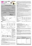
1
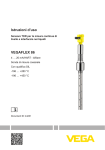
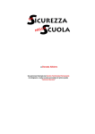
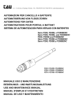
GUIDA ALL’INSTALLAZIONE INSTALLATION GUIDE TAU WIRELESS (vers. 6.03 e successive / vers. 6.03 and later) D-MNL0TWM-C 02-12-2014 - Rev.15 Sistema wireless per gestione periferiche di sicurezza e controllo Wireless system for management of safety and control peripherals IT - Istruzioni originali Via Enrico Fermi, 43 - 36066 Sandrigo (VI) Italia Tel +39 0444 750190 - Fax +39 0444 750376 [email protected] - www.tauitalia.com TAU-WIRELESS 1 ITALIANO Questo manuale d’istruzioni contiene importanti informazioni riguardanti la sicurezza per l’installazione, è necessario leggere tutte le istruzioni prima di procedere all’installazione. Conservare con cura questo manuale anche per utilizzi futuri. Considerando i pericoli che si possono verificare durante l’installazione e l’uso di TAU-Wireless, per la massima sicurezza è necessario che l’installazione avvenga nel pieno rispetto di leggi, norme e regolamenti. Secondo la più recente legislazione europea, l’automazione di una porta o cancello ricade in quanto previsto dalla Direttiva 2006/42/CE (Direttiva Macchine) e nel particolare, alle norme: EN 13241-1 (norma armonizzata); EN 12445; EN 12453 ed EN 12635, che consentono di dichiarare la conformità alla direttiva macchine. Il presente manuale è destinato solamente al personale tecnico qualificato per l’installazione, nessuna altra informazione contenuta nel presente fascicolo può essere considerata d’interesse per l’utilizzatore finale! • L’uso di TAU-Wireless diverso da quanto previsto in queste istruzioni è vietato; usi impropri possono essere causa pericoli o danni a persone e cose. • Non eseguire modifiche su nessuna parte se non previste nelle presenti istruzioni; operazioni di questo tipo possono solo causare malfunzionamenti; TAU declina ogni responsabilità per danni derivati da prodotti modificati. • TAU-Wireless deve funzionare esclusivamente per interpolazione diretta TX-RX. • Per i collegamenti elettrici utilizzare conduttori adeguati come riportato nel capitolo “collegamenti”. • Accertarsi che l’alimentazione elettrica e gli altri parametri d’utilizzo corrispondano ai valori riportati nella tabella “caratteristiche tecniche”. • La realizzazione di dispositivi di sicurezza per porte e cancelli automatici è sottoposta alle seguenti normative: • EN 12453 Porte e cancelli industriali, commerciali e da autorimessa. Sicurezza in uso di porte motorizzate - Requisiti • EN 12978 - Porte e cancelli industriali, commerciali e da garage. Dispositivi di sicurezza per porte e cancelli motorizzate - Requisiti e metodi di prova. L’installazione ed il collegamento di TAU-Wireless con lo scopo di realizzare un dispositivo di sicurezza, senza soddisfare i requisiti di queste norme corrisponde a negligenza e deliberato abuso! Avvertenze particolari sull’idoneità all’uso di questo prodotto in relazione alla Direttiva “Compatibilità Elettromagnetica“ 2004/108/CE: questo prodotto è stato sottoposto alle prove relative alla compatibilità elettromagnetica nelle situazioni d’uso più critiche, nelle configurazioni previste in questo manuale di istruzioni ed in abbinamento con gli articoli presenti nel catalogo prodotti di TAU s.r.l. Potrebbe non essere garantita la compatibilità elettromagnetica se il prodotto è usato in configurazioni diverse o con altri prodotti non previsti; è vietato l’uso del prodotto in queste situazioni finché chi esegue l’installazione non abbia verificato la rispondenza ai requisiti previsti dalla direttiva. DICHIARAZIONE CE DI CONFORMITÀ Con la presente dichiariamo che il nostro prodotto: Sistema wireless (900TWC - 900TWM) è conforme alle seguenti disposizioni pertinenti: 1999/5/CE Apparecchiature Radio e apparecchiature terminali di telecomunicazione EN 954-1:1996 Categoria 2 Il Rappresentante Legale _________________________________________ Loris Virgilio Danieli 2 TAU-WIRELESS TAU Wireless è un dispositivo che consente di risolvere il problema dei collegamenti elettrici di bordi sensibili posti su ante in movimento e non. Il sistema è composto da : 1_ Base (TWM) che gestisce i sensori (via radio) ed i comandi da e per il quadro del cancello (via cavo). 2_ Sensore (TWC) che invia il segnale del bordo sensibile (ad esso collegato) con contatto NC o resistivo, da utilizzare come bordo sensibile fisso e/o bordo sensibile mobile. Tutti i dispositivi, base e sensori, sono dotati di un transceiver in grado di ricevere e trasmettere dati sulla frequenza standard di 868 MHz. TAU Wireless consente la possibilità di utilizzo come parte di un dipositivo di sicurezza sensibile alla pressione (PSPE), tramite la verifica dello stato del bordo sensibile: il bordo sensibile, di tipo a resistenza costante 8,2kohm o contatto NC (normalmente chiuso), viene verificato continuamente dal sensore TWC e lo stato di attivazione o meno viene inviato alla base TWM. Quest’ultima interpreta l’informazione ricevuta e la comunica alla centrale elettronica dell’automazione. Il sistema TAU Wireless è compatibile con tutte le centrali TAU. Nota: utilizzare il sistema TAU-Wireless solo ed esclusivamente con centrali di comando TAU. CARATTERISTICHE TECNICHE Alimentazione scheda TWM Corrente assorbita scheda TWM Alimentazione sensore TWC Portata massima Tensioni alimentazioni circuiti logici Grado di protezione contenitore TWM Grado di protezione contenitore TWC Temperatura di funzionamento 12/24V AC/DC 70 mA 2 pile stilo AA 1,5V 20 m 5V DC IP 44 IP 43 -20 °C ÷ +55 °C INSTALLAZIONE Tutte le operazioni d’installazione vanno eseguite in assenza di tensione all’impianto; nel caso sia presente la batteria tampone, è necessario scollegarla. VERIFICHE PRELIMINARI Verificare attentamente che i parametri di utilizzo siano concordi con i dati riportati nel capitolo “Caratteristiche tecniche”. In caso di dubbio non utilizzare il prodotto e richiedere chiarimenti al servizio di assistenza tecnica di TAU. Per il fissaggio del bordo sensibile, attenersi alle istruzioni allegate al prodotto. Per la corretta installazione, procedere come segue: 1_ Collocare il sensore TWC in prossimità del bordo sensibile fissando prima la staffetta di supporto (1 fig.1) con due viti (2 fig.1) adeguate alla struttura del cancello. Inserire la scheda TWC (3 fig.1) negli appositi supporti della base. 2_ Collegare il sensore TWC al bordo sensibile facendo passare i cavi all’interno del cancello (fig.2). Si consiglia di utilizzare cavi di sez. 0,5 mm². 3_ Individuare l’area più idonea alla collocazione della base TWM (si consiglia di utilizzare l’apposito contenitore ed ubicarla esternamente in prossimità della centrale elettronica, se quest’ ultima non è incorporata al motoriduttore). Nota: se il carter del motore è in metallo (es. serie BIG) è necessario collocare la base TWM esternamente al motore con l’apposito contenitore. Anche nei casi in cui il carter non è metallico è poco opportuno posizionare la base TWM in prossimità del vano motore ed in generale vicino a masse metalliche, per non compromettere l’efficienza di ricetrasmissione. 4_ Chiudere il contenitore scheda con il relativo coperchio (4 fig.1). TAU-WIRELESS 3 ITALIANO DESCRIZIONE E FUNZIONAMENTO ITALIANO FUNZIONAMENTO ▪ E possibile collegare fino a 8 sensori TWC alla base TWM (ogni sensore viene associato ad una delle 8 posizioni, contraddistinte dagli 8 led verdi presenti sulla base). ▪ Tramite dip-switches, si possono selezionare fino ad 8 canali radio diversi, per permettere l’installazione di più TWM nella stessa area. ▪ Ogni sensore è associabile ad una delle due uscite a relay disponibili, ovvero l’uscita 1 (contatto ai morsetti 5 - 9) e l’uscita 2 (contatto ai morsetti 5 - 8). Il contatto del relay è normalmente chiuso, ed in caso che il sensore sia in allarme (ingresso aperto) il contatto si apre. ▪ Il collegamento tra un sensore (TWC) e la base (TWM) viene indicato da un led verde (sulla base TWM) acceso fisso. La base (TWM) controlla lo stato di carica delle batteria dei sensori (TWC): se dovessero risultare scariche, il led verde del relativo sensore lampeggia lentamente. ▪ In caso di mancata comunicazione radio tra base (TWM) e sensore (TWC) si attiva l’uscita associata al sensore ed il relativo led verde lampeggia velocemente. Si attiva inoltre, l’uscita STOP (aprendo il contatto ai morsetti 5 – 7), per bloccare l’automazione come ulteriore sicurezza (se collegata all’ingresso STOP della centrale di comando). COLLEGAMENTI (figg. 4 - 5) COLLEGAMENTI ALLA MORSETTIERA - BASE TWM N° 1-2 3 4 5 6 7 8 9 J2 J3 J4 Funzione ALIMENTAZIONE FTEST SPIA Descrizione Ingresso alimentazione 12/24V AC/DC. Non collegato. Non collegato. Comune dei contatti COMUNE Da collegare SEMPRE direttamente al COMUNE della centrale di coCONTATTI mando. può essere utilizzato per collegare un buzzer per l’allarme di batteria scaSTART rica (solo per sistemi in corrente continua). STOP Contatto N.C. USCITA 2 Contatto N.C. USCITA 1 Contatto N.C. SELEZIONE Selezione alimentazione: ALIMENTAZIONE ponticello chiuso per 12V AC/DC, non ponticellare per 24V AC/DC. Selezione del collegamento all’ingresso bordo sensibile della centrale. SELEZIONE J3 inserito se la centrale è predisposta all’ingresso di tipo ON/OFF; BORDO SENSIBILE non ponticellare J3 se l’ingresso è resistivo a 8,2 KΩ. Non utilizzato. COLLEGAMENTI ALLA MORSETTIERA - SENSORE TWC N° 1-2 Funzione BORDO SENSIBILE Descrizione Ingresso contatto NC BORDO SENSIBILE (o BORDO SENSIBILE RESISTIVO) - costa fissa o mobile. IMPOSTAZIONE DIP-SWITCHES Dip 1 Dip 2 Dip 3 OFF OFF OFF ON OFF OFF OFF ON OFF ON ON OFF 4 Selezione del canale radio Canale radio 1 Canale radio 2 Canale radio 3 Canale radio 4 TAU-WIRELESS OFF OFF ON ON ON ON ON ON Canale radio 5 Canale radio 6 Canale radio 7 Canale radio 8 ITALIANO OFF ON OFF ON ATTENZIONE: Lasciare il dip 4 in OFF. PROGRAMMAZIONE DI UN SENSORE TWC NOTA BENE: PRIMA DI ESEGUIRE QUALSIASI OPERAZIONE, ASSICURARSI DI AVER RIMOSSO LE BATTERIE DA TUTTI I SENSORI TWC INUTILIZZATI / NON PROGRAMMATI. 1. Per entrare in modalità programmazione, sulla base TWM tenere premuto il pulsante P1, il led rosso PRG si accende fisso (i led verdi dei sensori già programmati rimangono accesi fissi). 2. Il led verde della prima posizione libera emette 1 lampeggio al secondo, indicando che il sensore sarà associato all’uscita 1, contatto ai morsetti 5 – 9. Se si vuole associare il sensore all'uscita 2, contatto ai morsetti 5 - 8, tenere premuto il pulsante P1 finchè il led verde emette 2 lampeggi al secondo. Per spostarsi sulla posizione successiva, premere brevemente il pulsante P1, il relativo led inizia a lampeggiare. 3. Premere il pulsante "Tasto programmazione" sul sensore TWC: il led rosso (della base TWM) si spegne. Il led verde, invece, dopo qualche secondo, da lampeggiante rimane acceso fisso. NOTA: per utilizzare il sensore TWC con bordi sensibili resistivi, premere il pulsante "Tasto programmazione Bordo resistivo" (vedi figg. 4 - 5). Attendere che il led del sensore programmato sia fisso prima di programmare un altro sensore. Se entro 30 secondi non viene programmato nessun TWC il TWM esce dalla programmazione (led rosso PRG spento). CANCELLAZIONE DI UN SENSORE 1. Sulla base TWM tenere premuto il pulsante P1, il led rosso PRG si accende fisso, quindi rilasciarlo. 2. Se necesario, premere nuovamente e ripetutamente il pulsante P1 per portarsi nella posizione del sensore da cancellare (il relativo led verde lampeggia). 3. Tenere premuto il pulsante P1 finchè il led rosso PRG inizia a lampeggiare, quindi rilasciarlo. 4. Confermare la cancellazione premendo brevemente il pulsante P1. CANCELLAZIONE DI TUTTI I SENSORI 1. Tenere premuto il pulsante P1 della base TWM, il led rosso PRG si accende fisso, quindi rilasciarlo. 2. Tenere premuto il pulsante P1, il led rosso PRG lampeggia, quindi rilasciarlo. 3. Tenere premuto il pulsante P1 finchè tutti i led verdi lampeggino, quindi rilasciarlo. 4. Entro pochi secondi tutti i led verdi ed il led rosso si spengono. GARANZIA: CONDIZIONI GENERALI La garanzia della TAU ha durata di 24 mesi dalla data di acquisto dei prodotti (fa fede il documento fiscale di vendita, scontrino o fattura). La garanzia comprende la riparazione con sostituzione gratuita (franco sede TAU: spese di imballo e di trasporto sono a carico del cliente) delle parti che presentano difetti di lavorazione o vizi di materiale riconosciuti dalla TAU. TAU-WIRELESS 5 In caso di intervento a domicilio, anche nel periodo coperto da garanzia, l’utente è tenuto a corrispondere il “Diritto fisso di chiamata” per spese di trasferimento a domicilio, più manodopera. La garanzia decade nei seguenti casi: • Qualora il guasto sia determinato da un impianto non eseguito secondo le istruzioni fornite dall’azienda all’interno di ogni confezione. • Qualora non siano stati impiegati tutti componenti originali TAU per l’installazione dell’automatismo. • Qualora i danni siano causati da calamità naturali, manomissioni, sovraccarico di tensione, alimentazione non corretta, riparazioni improprie, errata installazione, o altre cause non imputabili alla TAU. • Qualora non siano state effettuate le manutenzioni periodiche da parte di un tecnico specializzato secondo le istruzioni fornite dall’azienda all’interno di ogni confezione. • Usura dei componenti. La riparazione o la sostituzione dei pezzi durante il periodo di garanzia non comporta un prolungamento del termine di scadenza della garanzia stessa. In caso di utilizzo industriale o professionale oppure in caso di impiego simile, tale garanzia ha validità 12 mesi. 6 TAU-WIRELESS - - -- - - - - - - - - - - - - - - - - - - - - - - - - - - - - - - - - - - - - - - - - - - - - - - - - - - - - - - - - - - - - - - - - - - - - - - - - - - - 4 3 1 2 TAU-WIRELESS fig. 1 7 3 2 1 fig. 3 8 TAU-WIRELESS 4 fig. 3 TAU-WIRELESS 9 SCHEMA CABLAGGIO DELLA BASE TWM AD UNA CENTRALE PER MOTORI IN 18V DC WIRING DIAGRAM OF TWM BASE TO A CONTROL UNIT FOR 18V DC MOTORS BORDO SENSIBILE FISSO FIXED SENSITIVE EDGE Tasto programmazione Bordo resistivo Programming pushbutton Fixed safety edge TWC D PORTA BATTERIE AA 2x1,5V BATTERY HOLDER AA 2X1,5 V Tasto programmazione Programming pushbutton Contatto N.C. (Normalmente Chiuso) NC contact (Normally Closed) J2 BORDO SENSIBILE MOBILE MOBILE SENSITIVE EDGE Tasto programmazione Bordo resistivo Programming pushbutton Fixed safety edge TWC PORTA BATTERIE AA 2x1,5V BATTERY HOLDER AA 2X1,5 V Tasto programmazione Programming pushbutton Contatto N.C. (Normalmente Chiuso) NC contact (Normally Closed) fig. 4 10 TAU-WIRELESS J3 D8 D7 D6 D5 D4 D8 D7 D6 D2 D3 D5 D4 D3 D2 D1 PRG D1 PRG Tasto programmazione Programming pushbutton TWM J2 J3 RX Collegare in serie il contatto di un eventuale pulsante di STOP o selettore a chiave. Connect the contact in series to any STOP pushbutton or key selector. 12345 Alimentazione Power supply Collegare in serie il contatto di un eventuale bordo sensibile aggiuntivo. Connect the contact in series to any additional sensitive edge. Fotocellule Photocells TX 12 Collegare in serie il contatto di una eventuale coppia di fotocellule aggiuntiva. Connect the contact in series to any additional pair of photocells. fig. 4 TAU-WIRELESS 11 SCHEMA CABLAGGIO DELLA BASE TWM AD UNA CENTRALE PER MOTORI IN 230V AC WIRING DIAGRAM OF TWM BASE TO A CONTROL UNIT FOR 230V AC MOTORS BORDO SENSIBILE FISSO FIXED SENSITIVE EDGE Tasto programmazione Bordo resistivo Programming pushbutton Fixed safety edge TWC PORTA BATTERIE AA 2x1,5V BATTERY HOLDER AA 2X1,5 V Tasto programmazione Programming pushbutton Contatto N.C. (Normalmente Chiuso) NC contact (Normally Closed) J2 J3 Antenna BORDO SENSIBILE MOBILE MOBILE SENSITIVE EDGE Tasto programmazione Bordo resistivo Programming pushbutton Fixed safety edge TWC PORTA BATTERIE AA 2x1,5V BATTERY HOLDER AA 2X1,5 V U1A Tasto programmazione Programming pushbutton U10 Contatto N.C. (Normalmente Chiuso) NC contact (Normally Closed) U8 fig. 5 12 TAU-WIRELESS D8 D7 D6 D5 D4 D8 D7 D2 D3 D5 D6 D4 D3 D2 D1 PRG D1 PRG Tasto programmazione Programming pushbutton TWM J2 J3 RX M4 12345 Alimentazione Power supply CF 2CH- 1 0 Vac 2CH- 2 0 Vac 24Vac 24V SPIA Antenna 24V FOT Collegare in serie il contatto di un eventuale pulsante di STOP o selettore a chiave. Connect the contact in series to any STOP pushbutton or key selector. COM FOT M3 D705M-1V0 GND FCA FCC GND ENC GND +5V CH AP T1 K3 U5 COM C13 STOP F2 P.P. AP CH CF FOT FCC COM 24V FCA 0V DL7 DL9 DL6 DL5 DL4 DL3 DL2 DL1 DL8 (24V) M2 PED 12V J1 12 Collegare in serie il contatto di una eventuale coppia di fotocellule aggiuntiva. Connect the contact in series to any additional pair of photocells. TF. SEC STOP F1 TX Collegare in serie il contatto di un eventuale bordo sensibile aggiuntivo. Connect the contact in series to any additional sensitive edge. PP PED VR2 K5 Fotocellule Photocells 0V (12V) G3 U2 U1A C4 LAMP 0 Vac U9 LAMP 230 Vac C38 U11 G1 C43 U10 CH T2 G2 U4 C45 K6 AP PR1 K4 COM FR + - 0V (80V) DL10 80V K2 VR1 TL P2 (230V) C3 230V K1 F2 TCA U1 - TF.PRIM 0V + - U8 M1 P1 FASE 230 Vac + C5 F1 NEUTRO fig. 5 TAU-WIRELESS 13 14 fig. 2 - - -- - - - - - - - - - - - - - - - - - - - - - - - - - - - - - - - - - - - - - - - - - - - - - - - - - - - - - - - - - - - - - - - - - - - - - - - - - - - TAU-WIRELESS EC DECLARATION OF CONFIRMITY We hereby declare that our product: Wireless system (900TWC - 900TWM) complies with the following relevant provisions: 1999/5/CE Radio equipment and telecommunications terminal equipment EN 954-1:1996 Class 2 The legal Representative _________________________________________ Loris Virgilio Danieli TAU-WIRELESS 15 ENGLISH This instruction manual contains important information regarding installation safety; therefore read all instructions carefully before proceeding with installation. Keep this manual in a safe place for future use. To ensure the maximum safety, in consideration of the hazards that may arise during installation and use of TAU-Wireless, the installation procedures must be performed in full compliance with the law, current standards and regulations. According to the most recent European legislation, the automation of a door or gate is subject to the specifications of the Machinery directive 2006/42/EC and more specifically to the standards: EN 13241-1 (harmonised standard); EN 12445; EN 12453 and EN 12635, which enable declaration of conformity with the Machinery Directive. This manual is intended exclusively for technical personnel qualified for installation; no other information in this document may be considered of interest to the final user. • Use of TAU-Wireless other than as specified in this instruction manual is strictly prohibited; improper use constitutes a risk of physical injury or damage to objects. • Do not perform any modifications to parts unless envisaged in these instructions; operations of this kind will only lead to malfunctions; TAU declines all liability for damage caused by modified products. • TAU-Wireless must operate exclusively for direct TX-RX interpolation. • For electrical connections, use suitable wires with sections as specified in the chapter “connections”. • Ensure that the electrical power supply and other operating parameters correspond to the values specified in the table “technical specifications”. • The installation of safety devices on power-operated doors and gates is subject to the following standards: • EN 12453 Industrial, commercial and residential doors and gates. Safety in use of power-operated doors and gates - Requirements • EN 12978 Industrial, commercial and residential doors and gates. Safety devices for power-operated doors and gates – Requirements and test methods. The installation and connection of TAU-Wireless with the aim of obtaining a safety device, without meeting the requirements of these standards constitutes a negligent and deliberate violation of the law! Specific warnings regarding the suitability of use of this product in relation to the directive “Electromagnetic Compatibility“ 2004/108/EC and subsequent amendments 92/31/EEC and 93/68/EEC: This product has undergone testing for electromagnetic compatibility in the most critical situations of use, in the configurations as envisaged in this manual and in conjunction with the articles stated in the catalogue produced by TAU s.r.l. Electromagnetic compatibility may not be guaranteed if the product is used in different configurations or with products not envisaged herein. Use of the product in such situations is strictly prohibited unless the installer has verified that all requirements as envisaged by the directive have been met. ENGLISH DESCRIPTION AND OPERATION TAU Wireless is a device that allows to solve the problem of the electrical connection of the proximity edges on moving and static gates. The system consists of: 1_ Base (TWM) that manages the sensors (via radio) and the controls from and to the gate panel (via cable). 2_ Sensor (TWC) that sends the signal of the proximity edge (connected to it) with NC or resistive contact, to be used as fixed and/or movable proximity edge. All devices, both base and sensors, are fitted with a transceiver capable of receiving and transmitting data on the standard 868 MHz frequency. TAU Wireless can be used as part of a safety device sensitive to pressure (PSPE), through checking the status of the proximity edge. The proximity edge, of the 8.2kohm constant resistance or NC (normally closed) contact type, is continually monitored by the TWC sensor and its activation status is transmitted to the TWM base. This base interprets the received information and transmits it to the automation electronic unit. The TAU Wireless system is compatible with all TAU control units. Note: only use the TAU-Wireless system with TAU control units. TECHNICAL DATA TWM card power supply TWM card absorbed current TWC sensor power supply Maximum load Logical circuit supply voltage TWM housing protection rating TWC housing protection rating Operating temperature 12/24V AC/DC 70 mA 2 x AA 1,5V batteries 20 m 5V DC IP 44 IP 43 -20 °C ÷ +55 °C INSTALLATION The whole installation must be carried out with no voltage in the system; if a battery backup is connected, disconnect it. PRELIMINARY CHECKS Check carefully that the use parameters match the data in the “Technical data” chapter. If in doubt, don’t use the product and ask TAU technical service for clarification. To install the proximity edge, follow the instructions accompanying the product. For a correct installation, proceed as follows: 1_ Place the TWC sensor near the proximity edge fixing first the support bracket (1 in fig. 1) with 2 screws (2 in fig. 1) suitable to the gate. Insert the TWC card (3 in fig. 1) into the appropriate base supports. 2_ Connect the TWC sensor to the proximity edge guiding the cables inside the gate (fig. 2). We recommend 0.5mm² cables are used. 3_ Determine the best area for installing the TWM base (it is best to use the relevant housing and locate it on the outside near the electronic control unit provided the latter is not built into the gearmotor). Note: If the motor casing is made from metal (e.g. BIG series), the TWM base must be located outside the motor casing with the relevant housing. Even in the event the casing is not made from metal, it is not advisable to position the TWM base near the motor compartment or, more generally speaking, near metal objects as this might interfere with reception/ transmission efficiency. 4_ Close the card housing with the appropriate cover (4 in fig. 1). 16 TAU-WIRELESS ▪ It is possible to connect up to 8 TWC sensors to the TWM base (each sensor is associated to one of the 8 positions, marked by the 8 green LEDs on the base). ▪ Using dip-switches, it is possible to select up to 8 different radio channels, to allow several TWMs to be installed in the same area. ▪ Each sensor can be associated to one of the two available relay outputs, that is output 1 (contact to terminals 5 – 9) and output 2 (contact with terminals 5 – 8). The relay contact is normally closed and if the sensor is in alarm (open input), the contact opens. ▪ The connection of a sensor (TWC) to the base (TWM) is shown by a lit fixed green LED (on the TWM base). The base (TWM) controls the charge status of the sensor batteries (TWC): if they are low, the green LED of the relative sensor flashes slowly. ▪ If there is no radio communication between the base (TWM) and the sensor (TWC), the output associated to the sensor is activated and the relative green LED flashes in quick succession. The STOP outlet is also activated (opening the contact with terminals 5 – 7), to block the automation for further safety (if connected to the STOP input of the control unit). CONNECTIONS (figures 4 - 5) CONNECTIONS TO THE TERMINAL BLOCK – TWM BASE No. 1-2 3 4 5 6 7 8 9 J2 J3 J4 Function POWER SUPPLY FTEST WARNING LIGHT CONTACT COMMON START STOP OUTPUT 2 OUTPUT 1 POWER SUPPLY SELECTION Description 12/24V AC/DC power supply input Not connected. Not connected. Contact common ALWAYS connect directly to the COMMON on the control unit. can be used to connect a low battery alarm buzzer (only for DC systems). NC contact NC contact NC contact Power supply selection: closed jumper for 12V AC/DC, do not bridge for 24V AC/DC. Selection of the connection to the proximity edge input of the control unit. PROXIMITY EDGE J3 ON if the control unit is preset for the ON/OFF input; SELECTION do not bridge J3 if the input is 8.2 KΩ resistive. Not used. CONNECTIONS TO THE TERMINAL BLOCK – TWC SENSOR No. Function Description Input of the NC PROXIMITY EDGE (or RESISTIVE PROXIMITY EDGE) 1 - 2 PROXIMITY EDGE contact – fixed or mobile rib. IMPOSTAZIONE DIP-SWITCHES Dip-switch 1 Dip-switch 2 Dip-switch 3 OFF OFF OFF ON OFF OFF OFF ON OFF ON ON OFF OFF OFF ON ON OFF ON Radio channel selection Radio channel 1 Radio channel 2 Radio channel 3 Radio channel 4 Radio channel 5 Radio channel 6 TAU-WIRELESS 17 ENGLISH OPERATION OFF ON ON ON ON ON Radio channel 7 Radio channel 8 ENGLISH WARNING: Leave dip-switch 4 on OFF. TWC SENSOR PROGRAMMING ATTENTION: CHECK THAT ALL THE BATTERIES HAVE BEEN REMOVED FROM THE UNUSED / NON PROGRAMMED TWC SENSORS BEFORE CARRYING OUT ANY OPERATION. 1. To enter programming mode, keep button P1 on the TWM base pressed, the PRG red LED lights up (the sensors‘ green LEDs that have already been programmed stay on. 2. The green LED of the first free position flashes once a second showing the sensor shall be matched to output 1, contact with terminals 5 – 9. If you wish to match the sensor with output 2, contact with terminals 5 – 8, keep the P1 button pressed till the green LED flashes twice a second. To move to the following position, press the P1 button briefly, the relative LED starts to flash. 3. Press the “Programming” button on the TWC sensor: the red LED (on the TWM base) goes off. On the other hand the green LED stops flashing and is ON all the time. NOTE: to use the TWC sensor with resistive proximity edges, press the “Resistive Edge Programming” button (see figures 4 - 5). Wait for the LED of the programmed sensor to stay on with continuous light before trying to program another sensor. If no TWC is programmed within 30 seconds the TWM exits programming mode (PRG red LED goes OFF). CLEARING A SENSOR 1. Keep button P1 on the TWM base pressed, the PRG red LED comes on with continuous light, and release. 2. If necessary press button P1 repeatedly to get to the sensor position to be cleared (the relative green LED flashes). 3. Keep button P1 pressed till the PRG red LED starts flashing, and release. 4. Confirm by pressing button P1 briefly. CLEARING ALL SENSORS 1. Keep button P1 on the TWM base pressed, the PRG red LED comes on with continuous light, and release. 2. Keep button P1 pressed till the PRG red LED starts flashing, and release. 3. Keep button P1 pressed till all the green LEDs start flashing, and release. 4. The green LEDs and the red LED will go off in a few seconds. GUARANTEE: GENERAL CONDITIONS TAU guarantees this product for a period of 24 months from the date of purchase (as proved by the sales document, receipt or invoice). This guarantee covers the repair or replacement at TAU’s expense (ex-works TAU: packing and transport at the customer’s expense) of parts that TAU recognises as being faulty as regards workmanship or materials. 18 TAU-WIRELESS The guarantee does not cover the following cases: • If the fault was caused by an installation that was not performed according to the instructions provided by the company inside the product pack. • If original TAU spare parts were not used to install the product. • If the damage was caused by an Act of God, tampering, overvoltage, incorrect power supply, improper repairs, incorrect installation, or other reasons that do not depend on TAU. • If a specialised maintenance man does not carry out routine maintenance operations according to the instructions provided by the company inside the product pack. • Wear of components. The repair or replacement of pieces under guarantee does not extend the guarantee period. In case of industrial, professional or similar use, this warranty is valid for 12 months. TAU-WIRELESS 19 ENGLISH For visits to the customer’s facilities, also during the guarantee period, a “Call-out fee” will be charged for travelling expenses and labour costs. GARANZIA TAU: CONDIZIONI GENERALI La garanzia della TAU ha durata di 24 mesi dalla data di acquisto dei prodotti (fa fede il documento fiscale di vendita, scontrino o fattura). In caso di utilizzo industriale o professionale oppure in caso di impiego simile, tale garanzia ha validità 12 mesi. La garanzia comprende la riparazione con sostituzione gratuita (franco sede TAU: spese di imballo e di trasporto sono a carico del cliente) delle parti che presentano difetti di lavorazione o vizi di materiale riconosciuti dalla TAU. In caso di intervento a domicilio, anche nel periodo coperto da garanzia, l’utente è tenuto a corrispondere il “Diritto fisso di chiamata” per spese di trasferimento a domicilio, più manodopera. La garanzia decade nei seguenti casi: • Qualora il guasto sia determinato da un impianto non eseguito secondo le istruzioni fornite dall’azienda all’interno di ogni confezione. • Qualora non siano stati impiegati tutti componenti originali TAU per l’installazione dell’automatismo. • Qualora i danni siano causati da calamità naturali, manomissioni, sovraccarico di tensione, alimentazione non corretta, riparazioni improprie, errata installazione, o altre cause non imputabili alla TAU. • Qualora non siano state effettuate le manutenzioni periodiche da parte di un tecnico specializzato secondo le istruzioni fornite dall’azienda all’interno di ogni confezione. • Usura dei componenti. La riparazione o la sostituzione dei pezzi durante il periodo di garanzia non comporta un prolungamento del termine di scadenza della garanzia stessa. ESTENSIONE DI GARANZIA GRATUITA TAU ti offre 12 mesi di garanzia supplementare oltre alla garanzia legale. Per attivare gratuitamente 12 mesi di garanzia supplementare collegati al seguente link: http://www.tauitalia.com/it/garanzia.php Cerca l’etichetta sul motore (vedi schema esemplificativo), compila i campi richesti entro 4 settimane dalla data di acquisto e allega alla fattura/scontrino la mail di conferma che riceverai. Quadri di comando Codice Esempio: XXX00000 XX/XX/XX Quadri di comando con contenitore rev. 00 del 06/08/2014 Codice Via Enrico Fermi, 43 36066 Sandrigo (VI) - Italy Tel +39 0444 750190 Fax +39 0444 750376 [email protected] www.tauitalia.com Nr. Seriale Data