1
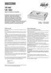
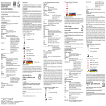
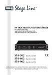
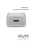
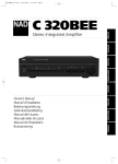
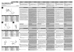
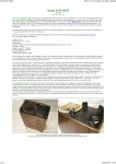
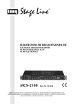
Velocity
Reference-Amplifier
VR 6000
Einbauanleitung / Bedienungsanleitung
Fitting instructions / Operating instructions
Instructions de montage / Mode d’emploi
Istruzioni di montaggio / Istruzioni d’uso
Inbouwinstrukties / Gebruiksaanwijzing
Monteringsanvisning / Bruksanvisning
Instrucciones de montaje / Instrucciones de manejo
Instruções de montagem / Instrução de serviço
8 622 401 877
Einführung (D)
Herzlichen Glückwunsch zum Kauf dieses hochwertigen Car AudioVerstärkers. Die für die neuen Velocity-Verstärker geleistete Entwicklungsarbeit bietet Ihnen vollendeten Musikgenuß in Ihrem Fahrzeug.
Unsere Velocity-Verstärker enthalten alle typischen Produktmerkmale
eines HighEnd-Verstärkers, beinhalten darüber hinaus aber auch noch
einige technische Highlights wie z.B.:
• 1-Ohm-Stabilität (nur bei Stereo-Mode) für niederohmige
Verstärkersysteme mit hoher Leistung
• Variable Frequenzweichen für Hoch- und Tiefpasseinstellung
• Variable Eingangsspannung 0,3 - 8 V
• Transistoren für Leistungsversorgung in MOSFET-Technologie
• Vergoldete Schraubanschlüsse für Lautsprecher- und
Spannungsversorgung
Sicherheitshinweise
Einbau- und Anschlußvorschriften
Für die Dauer der Montage und des Anschlusses ist der Minuspol der
Batterie abzuklemmen.
Hierbei sind die Sicherheitshinweise des Kfz-Herstellers (Airbag, Alarmanlagen, Bordcomputer, Wegfahrsperren) zu beachten.
In Hinsicht auf Unfallsicherheit muß die Velocity Endstufe professionell
befestigt werden. Die Montagefläche muß zur Aufnahme der beiliegenden Schrauben geeignet sein und sicheren Halt bieten.
Beim Bohren von Löchern darauf achten, daß keine Fahrzeugteile
(Batterie, Kabel, Sicherungskasten) beschädigt werden.
Der Amplifier wird an einem geeigneten Montageort z. B., unter den
Sitzen oder im Kofferraum montiert Fig. 1.
• Bass-Boost
Bei der Auswahl des Einbauortes sollte eine trockene Stelle ausgewählt
werden, die ausreichende Luftzirkulation für die Kühlung des Verstärkers
gewährleistet.
• Verchromtes Verstärkergehäuse
An scharfkantigen Löchern Kabeldurchführungen verwenden.
• Preamp-Out vergoldet
Für eine bestmögliche Klangqualität empfehlen wir Ihnen den Einbau
Ihres neuen Velocity-Verstärkers durch einen autorisierten VelocityHändler sowie die Verwendung der dazugehörigen Velocity-Lautsprechersysteme. Sie bringen die Leistungsstärke Ihres Verstärkers erst richtig
zur Geltung.
Gestatten Sie uns abschließend noch ein Wort zum Thema Gesundheitsschutz: Bitte bedenken Sie bei der Musikwiedergabe in Ihrem
Fahrzeug, daß dauerhafte Schalldruckpegel oberhalb von
100 dB zu bleibenden Schädigungen des menschlichen Ohres bis hin
zum vollständigen Verlust des Gehörs führen können. Mit modernen
Hochleistungssystemen und hochwertigen Lautsprecherkonfigurationen
sind Schalldruckpegel von über 130 dB zu erreichen.
Weitere Informationen über unsere Velocity- Serie finden Sie auch
unter unserer Internet-Adresse http://www.velocity.de
Lautsprecher mit 1-2-4 Ω Impedanz verwenden. Max. Belastbarkeit
(Musikleistung) beachten.
Lautsprecheranschlußkabel bis 16 mm2 verwenden. Lautsprecher
nicht an Masse schließen, nur die bezeichneten Klemmen verwenden.
Der Querschnitt des Plus und Minuskabels darf 16 mm2 nicht unterschreiten.
Das Pluskabel zwischen Batterie und Amplifier direkt an der Batterie
absichern.
Velocity Reference Amplifier VR 6000
stellung ist!
Der Amplifier eignet sich zum Anschluß an Autoradios mit CinchAnschluß.
Preamp - INPUT
Vorverstärker- Eingang für rechten (right) und linken (left) Kanal. Zu
diesem Anschluß verwenden Sie hochwertige Velocity-Chinch / RCAKabel.
Für den Anschluß an Autoradios mit ISO-Anschluß Blaupunkt
ISO- Cinch Adapter verwenden.
LP / HP / FULL - Schalter
Einsatzmöglichkeiten und Lautsprecheranschluß:
Selektieren Sie vor der Montage den Crossover Schalter der Endstufe
um den Tiefpassfilter (LP), den Hochpassfilter (HP) oder Fullrange
(Full) einzustellen. Bei der Position Full wird der volle Frequenzgang
am Ausgang benutzt.
VR 6000
Max Power
4 Ohm
Max Power
2 Ohm
Max Power
1 Ohm
RMS Power
4 Ohm
RMS Power
2 Ohm
RMS Power
1 Ohm
Frequenzgang
- 3 dB
Signal-Rauschabstand
Eingangsempfindlichkeit
Hochpassfilter
(High Pass)
Tiefpassfilter
(Low Pass)
Abmessungen
BxHxT (mm)
4x110 + 2x220 Watt
Fig. 5
4x160 + 2x300 Watt
Fig. 5
4x180 + 2x360 Watt
Fig. 5
4x55 + 2x110 Watt
(THD @ 0,05 %)
4x80 + 2x150 Watt
(THD @ 0,1 %)
4x90 + 2x180 Watt
(THD @ 0,2 %)
10 Hz - 60 kHz
Fig. 5
Der Einsatz der integrierten Frequenzweichen ist vor allen sinnvoll bei
Mehrwege- Soundsystemen mit separatem Subwoofer.
Um einen Subwoofer sinnvoll zu betreiben und somit den besten Klang
zu erreichen, ist es notwendig diesen frequenzmäßig abzukoppeln um
ihm nur die tiefen (Bässe) Frequenzen zuzuführen.
Um dieses zu tun wählen Sie LP und regeln Sie mit Hilfe des Übergangsfrequenzreglers die obere Frequenz zwischen 40 Hz und 120 Hz. Somit
wird jeder Subwoofer optimal abgekoppelt.
Fig. 5
Bei der Selektion HP kann mit dem zugehörigen Übergangsfrequenzregler die untere Grenzfrequenz zwischen 40 Hz und 250 Hz variiert
werden.
Fig. 5
Zur genauen akustischen Abstimmung der Frequenzweiche empfehlen
wir Ihnen die Beratung durch einen Velocity Fachhändler.
Die technischen Daten der eingesetzten Lautsprecher müssen bei der
Abstimmung der Frequenzweiche unbedingt berücksichtigt werden.
> 95 dB
0,3 - 8 V
Übergangsfrequenzregler (LP + HP)
40 - 250 Hz
Ist über den Crossover Schalter die Frequenzweiche aktiviert (Lowpass
oder Highpass), kann mit dem entsprechenden Regler die Übergangsfrequenz des jeweiligen Filters zwischen 40 Hz und 250 Hz stufenlos
eingestellt werden. Bei Fullrange- Betrieb ist dieser Regler ohne Funktion.
40 - 120 Hz
(18 dB / Oct.)
232,6 x 59,5 x 620
Integrierte Sicherungen (FUSE)
Die im Amplifier integrierten Sicherungen (Fuse) schützen die Endstufe
und das gesamte elektrische System im Fehlerfall. Bei dem Einsatz einer
Ersatzsicherung bitte niemals Sicherungen überbrücken oder gegen
Typen mit höherem Strom auswechseln.
Tri - Mode
Sie können 2 Lautsprecher(4Ω) betreiben und gleichzeitig einen
dritten Lautsprecher (4Ω) im Mono - Betrieb (Brückenbetrieb)
dazuschalten.
Betriebsanzeige (POWER / PROTECT)
Plus-/Minus-Anschluß
Grünes Licht: Endstufe an, regulärer Betriebszustand
Wir empfehlen einen Mindestquerschnitt von 16 mm2. Handelsübliche
Pluskabel zur Batterie verlegen und über Sicherungshalter anschließen.
Den Sicherungshalter in der Nähe der Batterie anschließen.
Rotes Licht: Endstufe ist elektronisch abgeschaltet da Fehlerfall vorliegt.
Änderungen vorbehalten!
An scharfkantigen Löchern Kabeldurchführungen verwenden.
Handelsübliche Minuskabel an einen störfreien Massepunkt
(Karosserieschraube, Karosserieblech) sicher anschrauben (nicht am
Minuspol der Batterie). Kontaktfläche des Massepunktes metallisch
blank kratzen und mit Graphitfett einfetten.
Anschlußbeispiele
Anschluß der Spannungsversorgung ........................................... Fig. 2
Anschluß an Autoradios mit Cinch-Ausgang ............................... Fig. 3
Anschluß an Autoradios mit Lautsprecher-Ausgang .................... Fig. 4
Lautsprecheranschlüsse .............................................................. Fig. 5
Beim Anschluß über die Cinch- oder Lautsprecherbuchsen des Autoradios muß die Schaltleitung angeschlossen werden.
+12V
Regler GAIN
Mit Hilfe des Gain Reglers kann die Eingangsempfindlichkeit der Velocity
Endstufe an die Ausgangsspannung Ihres Autoradio- Vorverstärkerausganges angepaßt werden.
Der Einstellbereich reicht von 0,3 V bis 8 V.
Bei Anschluß eines Autoradios anderer Hersteller ist die Eingangsempfindlichkeit entsprechend den Herstellerangaben anzupassen.
Bitte bemerken Sie das der Gain Adjust Regler keine Lautstärkeein8 622 401 877
2
Introduction (GB)
Velocity ReferenceAmplifier VR 6000
The amplifier is suitable for connecting to car radios with cinch connector.
Congratulations on purchasing this high-quality Car Audio Amplifier. The
development work invested in the new Velocity Amplifier offers you
complete music enjoyment in your car. Our Velocity Amplifiers are fitted
with all typical product features expected from a high-end amplifier, but
also contain a number of technical highlights as well, such as:
Use the Blaupunkt ISO-Cinch Adapter for connecting to car radios with
ISO connector.
Possibilities for use and switching:
• 1 ohm stability (only in stereo mode) for low-ohm amplifier systems
with high performance
VR 6000
• Variable frequency dividers for high and low pass setting
• Variable input voltage 0.3 - 8 V
• Transistors for power supply using MOSPET technology
• Gold-plated screw connectors for loudspeaker and power supply
• Preamp-Out gold-plated
• Bass-Boost
• Chrome-plated amplifier housing
To achieve the best possible sound quality from your new Velocity
Amplifier we recommend that it is installed by an authorised Velocity
dealer and that the matching Velocity Loudspeaker system is used. This
is the way to obtain the full enjoyment of the performance of your
amplifier.
Let us finally mention the aspect of health safety. Please remember when
listening to music in your car that constant sound-pressure levels of more
than 100 dB can cause permanent damage to the human ear right up to
complete loss of hearing. Sound-pressure levels of more than 130 dB
can be achieved with modern high-performance systems and highquality loudspeaker configurations.
You can also obtain further information on our Velocity Series at our
Internet address http://www.velocity.de
Max Power
4 Ohm
Max Power
2 Ohm
Max Power
1 Ohm
RMS Power
4 Ohm
RMS Power
2 Ohm
RMS Power
1 Ohm
Freq. response
- 3 dB
Signal-to-Noise
Ratio
Input Level
0,3 - 8 V
High Pass
40 - 250 Hz
Low Pass
40 - 120 Hz
(18 dB / Oct.)
232.6 x 59.5 x 620
Dimensions
WxHxD (mm)
Safety instructions
4x110 + 2x220 W
Fig. 5
4x160 + 2x300 W
Fig. 5
4x180 + 2x360 W
Fig. 5
4x55 + 2x110 W
(THD @ 0.05 %)
4x80 + 2x150 W
(THD @ 0.1 %)
4x90 + 2x180 W
(THD @ 0.2 %)
10 Hz - 60 kHz
Fig. 5
Fig. 5
Fig. 5
> 95 dB
Rules to be observed in fitting and connection
Disconnect the negative pole of the car battery for the duration of the
installation and connection works.
Tri-Mode
Allows you to drive two loudspeakers (4Ω) and to connect a third
speaker (4Ω) in mono operation (bridged mode).
The safety instructions of the car manufacturer (airbag, alarm systems,
on-board computers, engine immobilizers) must be observed.
With regard to accident prevention the Velocity power amplifier must be
affixed in a professional manner. The mounting surface must be suitable
for accepting the enclosed screws and must offer secure installation.
Positive/negative connections
We recommend a minimum cross-section of 16 mm2. Lay commercially
available positive cable to the battery and connect using fuse holder. The
fuse holder should be connected close to the battery.
When drilling holes please ensure that no car components are damaged
(battery, cables, fuse box).
Use cable bushings at sharp-edged holes. Screw the commercially
available negative cable firmly to an interference-free earthing-point (car
body bolt, car body sheet, but not to the negative battery pole). Scrape
the contact surface of the earthing point until it is blank metal and coat
with graphite grease.
The amplifier should be installed at a suitable location, i.e. under the
seats or in the boot, Fig. 1.
A dry position should be selected for the installation location that
guarantees sufficient air circulation for the cooling of the amplifier.
Use cable bushings at sharp-edged holes.
Use loudspeakers with 1-2-4 ohm impedance. Pay attention to the max.
loading (music output).
Connection examples:
Use 16 mm2 loudspeaker connection cables. Do not connect the
loudspeakers to earth, use only the designated terminals.
Connection of car radio with cinch output ................................... Fig. 3
Connection of power supply ........................................................ Fig. 2
Connection of car radio with loudspeaker output ........................ Fig. 4
The cross-section of the positive and negative cable may not be less than
16 mm2.
Loudspeaker connections ........................................................... Fig. 5
Fit a fuse holder to the positive cable between the battery and the
amplifier directly at the battery.
When connecting via the cinch or loudspeaker sockets of the car radio
the switch cable must be connected.
+12V
Controller (GAIN)
Using the Gain Controller you can adjust the input sensitivity of the
Velocity Power Amplifier to the output voltage of your car radio preamplifier output.
The adjusting range is from 0.3 V to 8 V.
When connecting a car radio from other manufacturers the input sensitivity
should be adapted in accordance with the specifications of the
manufacturer.
8 622 401 877
3
Introduction (F)
Please note that the Gain Adjust Controller is not designed for volume
adjustment!
Sincères félicitations pour l’achat de cet amplificateur audio de qualité
supérieure. Le travail consacré au développement des nouveaux
amplificateurs Velocity vous offre une réception parfaite de la musique
dans votre véhicule. Nos amplificateurs Velocity présentent toutes les
caractéristiques typiques d’un amplificateur HighEnd et en outre d’autres
caractéristiques excellentes comme par ex.:
Preamp-INPUT
Please use high-quality Velocity cinch/RCA cables for connecting the
pre-amp input for right and left channels.
• Une stabilité de 1 ohm (uniquement en mode stéréo) pour des
systèmes d’amplification de basse impédance à haute puissance.
LP/HP/FULL switch
Prior to installation set the crossover switch of the power amplifier to the
desired position to select the low-pass filter (LP), the high-pass filter (HP)
or full range (Full). In the Full position the full frequency response at the
output is used.
• Des coupleurs variables pour le réglage passe-haut et passe-bas.
• Une tension d’entrée variable de 0,3 à 6 V.
• Des transistors pour l’alimentation en puissance en technologie
de dispositif MOS à effet de champ.
The use of the integrated frequency divider is sensible particularly with
multipath sound systems with separate subwoofer.
• Des raccords filetés dorés pour l’alimentation en courant et
l’alimentation des haut-parleurs.
To operate a subwoofer optimally and therefore to achieve the best
sound it is necessary to decouple the frequencies in such a way that only
the bass frequencies are fed to the subwoofer.
• Entrée préampli dorées
• Suramplificateur de basses
In order to do this please select LP and regulate the upper frequencies
between 40 Hz and 120 Hz using the crossover frequency control switch.
This causes each subwoofer to be decoupled in an optimum fashion.
• Boîtier d’amplificateur chromé
Pour atteindre la meilleure qualité sonore, nous vous recommandons de
faire installer votre nouvel amplificateur Velocity par un revendeur
Velocity autorisé et d’utiliser les systèmes de haut-parleurs Velocity y
appartenant qui mettent en valeur la haute puissance de votre
amplificateur.
By selecting HP the lower threshold frequency can be varied between 40
Hz and 250 Hz using the relevant crossover frequency controller.
To achieve exact acoustic agreement of the frequency divider we
recommend that you consult a Velocity dealer.
Permettez-nous finalement un mot concernant la protection sanitaire.
Songez que des niveaux de pression acoustique permanents au-dessus
de 100 dB lors de la reproduction musicale sont nuisibles à la santé et
peuvent même avoir pour conséquence la perte de l’ouïe. Les systèmes
performants modernes et les configurations de haut-parleurs de haute
qualité permettent d’atteindre des niveaux de pression acoustique de
plus de 130 dB.
The specifications of the loudspeakers used must be taken into account
without fail when carrying out the fine adjustment of the frequency
divider.
Crossover frequency controller (LP + HP)
If the frequency divider (low-pass or high-pass) has been activated using
the crossover switch, then it is possible to adjust the crossover frequency
of the relative filter between 40 Hz and 250 Hz in infinitely variable stages.
This controller has no function when the unit is set to Full Range mode.
Pour des informations supplémentaires sur notre gamme Velocity,
veuillez vous reporter à notre adresse internet http://www.velocity.de
Conseils de sécurité
Integrated fuses (FUSE)
Instructions de montage et de branchement
The fuses integrated into the amplifier protect the power amp and the
complete electrical system in the event of faults or failures. When
inserting a spare fuse, never replace with fuse types with a higher current
or bridge fuses.
Débrancher le pôle négatif de la batterie pendant les opérations de
montage et de branchement.
Respecter les conseils de sécurité du fabricant de votre véhicule (airbag,
dispositifs d’alarme, ordinateur de bord, blocages).
Green lamp: Power amp on, regular operating condition
Pour assurer la protection contre les accidents, l’étage de sortie Velocity
doit être fixée correctement. La surface de montage doit être appropriée
pour la réception des vis inclus et assurer un appui solide.
Red lamp: Power amp has been switched off electronically, due to a fault
or failure.
En perçant des trous, veiller à ce que des éléments du véhicule (la
batterie, les câbles, la boîte à fusibles) ne soient pas endommagés.
Subject to modifications!
Monter l’amplificateur à une place appropriée, par ex. sous les sièges ou
dans le coffre, voir fig. 1.
Operating indicator (POWER / PROTECT)
Sélectionner une place de montage sèche offrant une circulation d’air
suffisante pour le refroidissement de l’amplificateur.
Utiliser des traversées de câbles pour les trous à arêtes vives.
Utiliser des haut-parleurs d’une impédance de 1-2-4 ohms. Respecter la
puissance musicale maximum.
Utiliser un câble raccordement de haut-parleur de 16 mm2 au maximum.
Ne pas brancher le haut-parleur à la masse, utiliser uniquement les
bornes indiquées.
La section des câbles positif et négatif ne doit pas être inférieure à
16 mm2.
Protéger par fusibles le câble positif entre la batterie et l’amplificateur
directement à la batterie.
8 622 401 877
4
Amplificateur Reference Velocity VR 6000
Preamp-INPUT
L’amplificateur est approprié pour le branchement aux autoradios à
connexion Cinch.
Entrée de préamplificateur pour les canaux droit (right) et gauche (left).
Utiliser des câbles Velocity Cinch/RCA de qualité supérieure pour ce
branchement.
Utiliser des adaptateurs ISO Cinch pour le branchement aux autoradios
à connexion ISO.
Commutateur filtre basse-bas (LP), filtre passe-haut (HP), FULL
Possibilités d’utilisation et de commutation:
Avant d’effectuer le montage, sélectionner le commutateur Crossover
sur la surface supérieure de l’étage de sortie pour régler le filtre passebas, le filtre passe-haut ou fullrange (Full). La réponse en fréquence
complète est utilisée à la sortie en cas de réglage sur Full.
VR 6000
Puissance max.
4 Ohm
Puissance max.
2 Ohm
Puissance max.
1 Ohm
Puissance RMS
4 Ohm
Puissance RMS
2 Ohm
Puissance RMS
1 Ohm
Réponse en fréq.
- 3 dB
Rapport
signal/bruit
Sensibilité
d’entrée
Filtre passe-haut
(High Pass)
Filtre passe-bas
(Low Pass)
Dimensions
LxHxP (mm)
4x110 + 2x200 watts
Fig. 5
4x160 + 2x300 watts
Fig. 5
4x180 + 2x360 watts
Fig. 5
4x55 + 2x110 watts
(THD @ 0,05 %)
4x80 +2x150 watts
(THD @ 0,1 %)
4x90 + 2x180 watts
(THD @ 0,2 %)
10 Hz - 60 kHz
Fig. 5
Le coupleur intégré devrait être utilisé pour les systèmes sonores à
canaux multiples à subwoofer séparé.
Afin d’utiliser au mieux un subwoofer et d’atteindre la meilleure tonalité,
il est nécessaire de le découpler en fréquences pour lui amener
uniquement les fréquences basses (graves).
Pour ce faire, sélectionner le filtre passe-bas et régler la fréquence
supérieure entre 40 Hz et 120 Hz à l’aide du réglage de la fréquence de
recouvrement. Chaque subwoofer est ainsi découplé de manière optimale.
Fig. 5
En sélectionnant le filtre passe-haut, il est possible de varier la fréquence
inférieure de coupure entre 40 Hz et 250 Hz à l’aide du réglage de la
fréquence de recouvrement.
Fig. 5
> 95 dB
Pour assurer un réglage acoustique précis du coupleur, nous vous
recommandons de prendre contact avec un revendeur spécialisé Velocity.
0,3 - 8 V
Il est absolument nécessaire de prendre en compte les données
techniques des haut-parleurs utilisés lors du réglage du coupleur.
40 - 250 Hz
Réglage de la fréquence de recouvrement (LP + HP)
40 - 120 Hz
(18 dB / oct.)
232,6 x 59,5 x 620
Lorsque le coupleur est activé par le commutateur Crossover (Lowpass
ou Highpass), il est possible de régler progressivement la fréquence de
recouvrement du filtre respectif de 40 Hz à 250 Hz. Ce réglage est sans
fonction en cas de service fullrange.
Fusibles intégrés (FUSE)
L’étage de sortie et le système électrique complet sont protégés en cas
de défaillance par les fusibles (fuse) intégrés dans l’amplificateur. En cas
d’utilisation d’une fusible de rechange, ne jamais ponter les fusibles ou
les échanger contres des types à courant plus fort.
Tri-Mode (Fonctionnement avec trois haut-parleurs)
Vous avez la possibilité de faire fonctionner deux haut-parleurs (4Ω) et
de raccorder en même temps un troisième haut-parleur (4Ω) en mode
mono (fonctionnement en pont).
Indication de fonctionnement (POWER / PROTECT)
Branchement positif/négatif
Affichage vert: Etage de sortie connectée, état de fonctionnement
régulier.
Nous recommandons une section minimum de 16 mm2. Poser des
câbles positifs commerciaux vers la batterie et les brancher par un portefusible. Brancher le porte-fusible à proximité de la batterie.
Affichage rouge: L’étage de sortie est électroniquement déconnectée à
cause d’une défaillance.
Utiliser des traversées de câbles pour des trous à arêtes vives. Visser
des câbles négatifs commerciaux à un point masse libre de parasites (vis
de carrosserie, tôle de carrosserie) (non pas au pôle négatif de la
batterie). Gratter la surface de contact du point masse et la graisser à
l’aide de la graisse en graphite.
Sous réserve de modifications!
Exemples de branchement
Branchement de l’alimentation en courant ................................... fig. 2
Branchement aux autoradios à sortie Cinch ................................ fig. 3
Branchement aux autoradios à sortie de haut-parleur ................. fig. 4
Branchement de haut-parleurs .................................................... fig. 5
La ligne de commutation doit être branchée en cas de branchement par
la prise Cinch ou les prises de haut-parleur de l’autoradio.
+12V
Réglage (GAIN)
Le réglage Gain permet d’adapter la sensibilité d’entrée de l’étage de
sortie Velocity à la tension de sortie de la sortie du préamplificateur de
votre autoradio.
La gamme de réglage est de 0,3 V à 8 V.Lorsque vous branchez un
autoradio d’une autre marque, adapter la sensibilité d’entrée
conformément aux indications faites par le constructeur.
Veuillez prendre note que le réglage gain adjust ne sert pas à régler le
volume sonore.
8 622 401 877
5
Introduzione (I)
Velocity Reference Amplifier VR 6000
L‘amplificatore è adatto per il collegamento di autoradio con presa cinch.
Felicitazioni per l‘acquisto di questo amplificatore audio di qualità per
auto. Il perfezionamento tecnico degli amplificatori Velocity vi offre il
piacere di ascoltare musica nel vostro veicolo nel migliore dei modi. I
nostri amplificatori Velocity hanno tutte le caratteristiche tipiche di un
amplificatore high end, cui però si aggiunge anche qualche dato tecnico
di rilievo come p. es.:
Per il collegamento di autoradio con presa ISO Blaupunkt, utilizzare
l‘adattatore ISO-cinch.
Possibilità d‘impiego e di comando:
• Stabilità 1 ohm (solo in modalità stereo) per potenti sistemi di
amplificazione a bassa resistenza ohmica
VR 6000
Max Power
4 ohm
Max Power
2 ohm
Max Power
1 ohm
RMS Power
4 ohm
RMS Power
2 ohm
RMS Power
1 ohm
Risposta freq.
- 3 dB
Rapporto
segnale disturbo
Sensibilità
d’ingresso
Filtro passa alto
(High Pass)
Filtro passa basso
(Low Pass)
Dimensioni
LxAxP (mm)
• Separatori variabili di frequenze per la regolazione dei filtri passa
alto e passa basso
• Tensione d‘ingresso variabile 0,3-8 V
• Transistor per l‘alimentazione di potenza con tecnologia MOSFET.
• Collegamenti a vite dorati per gli altoparlanti e la tensione
d‘alimentazione
• Preamp-in dorati
• Bass-Boost
• Scatola di amplificatore cromata
Per ottenere la migliore qualità del suono possibile, vi consigliamo di far
eseguire il montaggio dei vostri nuovi amplificatori Velocity da un
rivenditore Velocity autorizzato, nonché di fare uso dei relativi sistemi di
amplificazione Velocity. Solo così potrete mettere veramente in risalto la
potenza dei vostri amplificatori.
Permetteteci, per concludere, di dire ancora una parola sul tema „Tutela
della salute“: Quando ascoltate musica nel vostro veicolo, dovete tener
presente che un livello di pressione acustica continuamente al disopra di
100 dB può danneggiare irrimediabilmente l‘orecchio umano e condurre
addirittura alla perdita totale dell‘udito. Con i potenti sistemi moderni, cui
si integrano altoparlanti di qualità, è possibile raggiungere un livello di
pressione acustica superiore a 130 dB.
Per ulteriori informazioni sulla nostra serie Velocity, collegatevi con il
nostro sito Internet all‘indirizzo: http://www.velocity.de
Indicazioni di sicurezza
4x110 + 2x200 W
Fig. 5
4x160 + 2x300 W
Fig. 5
4x180 + 2x360W
Fig. 5
4x55 + 2x110 W
(THD @ 0,05 %)
4x80 + 2x150 W
(THD @ 0,1 %)
4x90 + 2x180 W
(THD @ 0,2 %)
10 Hz - 60 kHz
Fig. 5
Fig. 5
Fig. 5
> 95 dB
0,3 - 8 V
40 - 250 Hz
40 - 120 Hz
(18 dB / Oct.)
232,6 x 59,5 x 620
Tri-Mode
Disposizioni per il montaggio e il collegamento
Potete mettere in funzione 2 altoparlanti (4Ω) ed inoltre inserire
contemporaneamente un terzo altoparlante (4Ω) in funzione mono
(funzionamento a ponte).
Per la durata del montaggio e del collegamento è necessario che il polo
negativo della batteria resti staccato.
Occorre rispettare le indicazioni di sicurezza del fabbricante del veicolo
(pallone anti-incidente, impianto d‘allarme, computer di bordo, dispositivo
di blocco dell‘accensione).
Collegamento positivo/negativo
Raccomandiamo una sezione minima di 16 mm2. Posare i cavi positivi,
di un tipo fra quelli normalmente in commercio, fino alla batteria, e
collegarli con il portafusibili. Collegare il portafusibili in prossimità della
batteria.
Per quanto riguarda la sicurezza in caso d‘incidente, è necessario fissare
l‘amplificatore di potenza Velocity in modo professionale. La superficie
di montaggio deve essere adatta per accogliere le viti comprese nella
fornitura, e deve offrire un appoggio sicuro.
Laddove vi sono fori con bordi taglienti, utilizzare passacavi. Collegare
a massa i cavi negativi, di un tipo fra quelli normalmente in commercio,
scegliendo un punto di massa non soggetto a disturbi (bullone o lamiera
della carrozzeria); non collegare i cavi negativi con il polo negativo della
batteria. Grattare per mettere a nudo il metallo della superficie di contatto
del punto di massa; ingrassare la superficie con grasso grafitato.
Quando si praticano i fori, badare a non danneggiare nessuna parte del
veicolo (batteria, cavo, contenitore dei fusibili).
L‘amplificatore viene montato in un luogo appropriato, p. es. sotto i sedili
o nel vano portabagagli (fig. 1).
Al momento della scelta del luogo di montaggio, occorre scegliere un
posto asciutto che garantisca una circolazione sufficiente dell‘aria per il
raffreddamento dell‘amplificatore.
Esempi di collegamento
Laddove vi sono fori con bordi taglienti, utilizzare passacavi.
Collegamento della tensione d‘alimentazione ............................. Fig. 2
Utilizzare altoparlanti con un‘impedenza di 1-2-4 ohm. Rispettare la
carica ammissibile (potenza musicale).
Collegamento di autoradio con uscita cinch ............................... Fig. 3
Collegamento di autoradio con uscita per
altoparlanti .................................................................................. Fig. 4
Utilizzare cavi per il collegamento degli altoparlanti con una sezione max.
di 16 mm2. Non collegare gli altoparlanti con la terra; utilizzare
esclusivamente i morsetti indicati.
Attacchi per altoparlanti .............................................................. Fig. 5
La sezione dei cavi positivo e negativo non deve essere inferiore a
16 mm2.
In caso di collegamento tramite le prese cinch o per altoparlanti
dell‘autoradio, occorre collegare la direzione di rete.
+12V
Proteggere con fusibile il cavo fra batteria e amplificatore direttamente
all‘altezza della batteria.
Regolatore (GAIN)
Con l‘ausilio del regolatore Gain è possibile adattare la sensibilità
d‘ingresso dell‘amplificatore di potenza Velocity alla tensione d‘uscita del
preamplificatore della vostra autoradio.
Il campo di regolazione varia fra 0,3 V e 8 V.
Se si collega un‘autoradio di un altro fabbricante, occorre adattare la
sensibilità d‘ingresso attenendosi alle indicazioni del fabbricante.
8 622 401 877
6
Inleiding (NL)
Tenete presente che il regolatore Gain Adjust non è un regolatore di
volume!
Hartelijk gefeliciteerd met de aankoop van deze hoogwaardige autoaudioversterker. Het resultaat van het werk aan de ontwikkeling van de
nieuwe Velocity-versterker biedt u volmaakt muziekgenot in uw auto.
Onze Velocity-versterkers hebben alle typerende productkenmerken
van een HighEnd-versterker en beschikken bovendien over een aantal
technische hoogstandjes zoals:
Preamp-INPUT
Ingresso preamplificatore per canale destro (right) e sinistro (left).
Utilizzate per questa presa cavi di qualità Velocity cinch/RCA.
• 1-Ohm-stabiliteit (alleen in de stereo-modus) voor versterkersystemen met lage impedantie en hoog uitgangsvermogen
Interruttore LP/HP/FULL
Prima del montaggio, servitevi dell‘interruttore Crossover sul lato superiore
dell‘amplificatore di potenza per regolare il filtro passa basso (LP), il filtro
passa alto (HP) o la portata Fullrange (Full). In posizione Full viene
utilizzata in uscita l‘intera risposta frequenziale.
• Variabele frequentiefilters voor hoog- en laagdoorlaatinstelling
• Variabele ingangsspanning 0,3 - 8 V
• Transistoren voor uitgangsvermogen volgens MOSFETtechnologie
L‘impiego di separatori di frequenze integrati ha un senso esclusivamente
nel caso di sistemi sound a più vie con altoparlante separato subwoofer.
• Vergulde schroefaansluitingen voor luidsprekeraansluiting en
voeding
Affinché il subwoofer permetta veramente di ottenere il suono migliore,
è necessario che questo altoparlante riceva solo le basse frequenze.
• Preamp-in, verguld
Ciò è possibile selezionando LP, e, con l‘ausilio del regolatore della
frequenza di transizione, regolando la frequenza superiore fra 40 Hz e
120 Hz. In tal modo ogni subwoofer riceverà esclusivamente basse
frequenze.
• Bass-boost
• Verchroomde versterkerkast
Voor een optimale klankkwaliteit raden wij u aan uw nieuwe Velocityversterker te laten inbouwen door een geautoriseerde Velocity-dealer en
bijbehorende Velocity-luidsprekersystemen te gebruiken. Zo komt het
vermogen van uw versterker pas echt tot z‘n recht.
Selezionando HP è possibile, con il relativo regolatore di frequenza di
transizione, di modificare la frequenza limite inferiore fra 40 Hz e 250 Hz.
Per una regolazione acustica precisa del separatore di frequenze, vi
consigliamo di rivolgervi ad un rivenditore specializzato Velocity.
Sta ons tot slot toe enkele woorden te besteden aan de bescherming van
uw gezondheid. Bedenk bij de muziekweergave in uw auto dat langdurige
blootstelling aan geluidsniveaus boven 100 dB kan leiden tot blijvende
beschadiging van het menselijk gehoor en zelfs tot volledige doofheid.
Met moderne systemen met hoge vermogens en hoogwaardige
luidsprekerconfiguraties kunnen geluidsdrukniveaus van meer dan 130
dB worden bereikt.
Al momento di regolare il separatore di frequenze, occorrerà far riferimento
assolutamente ai dati tecnici degli altoparlanti utilizzati.
Regolatore della frequenza di transizione (LP + HP)
Attivando tramite l‘interruttore Crossover il separatore di frequenze
(Lowpass o Highpass), è possibile regolare la frequenza di transizione
del filtro selezionato fra 40 Hz e 250 Hz con il rispettivo regolatore
continuo. In modalità Fullrange, questo regolatore è inattivo.
Nadere informatie over onze Velocity-serie vindt u ook op ons
internetadres: http://www.velocity.de
Aanwijzingen voor de veiligheid
Fusibili integrati (FUSE)
Voorschriften voor inbouw en aansluiting
I fusibili (Fuse) integrati nell‘amplificatore proteggono l‘amplificatore di
potenza e tutto il sistema elettrico in caso di guasto. Quando cambiate
un fusibile, non shuntate mai i fusibili e non sostituiteli con tipi resistenti
a correnti più alte.
Voor de duur van de montage en de aansluiting moet de minpool van de
accu worden losgekoppeld.
Spia indicatrice di stato (POWER / PROTECT)
Met het oog op de voorkoming van ongevallen moet de Velocity-eindtrap
professioneel worden bevestigd. Het montage-oppervlak moet geschikt
zijn voor de bevestiging van de meegeleverde schroeven en een stevige
ondergrond vormen.
Hierbij moeten de veiligheidsvoorschriften van de autofabrikant (airbag,
alarminstallaties, boordcomputer, wegrijblokkering) in acht worden
genomen.
Luce verde: amplificatore di potenza in funzione, stato normale
Luce rossa: disinserzione elettronica dell‘amplificatore di potenza a
seguito di guasto.
Let er bij het boren van gaten op dat er geen onderdelen van de auto
beschadigd raken (accu, kabels, zekeringkast).
Con riserva di apporto modifiche!
De versterker wordt gemonteerd op een geschikte plaats, bv. onder de
stoel of in de kofferruimte (fig. 1).
Voor de inbouw moet een droge plaats worden gekozen waar voldoende
luchtcirculatie voor de koeling van de versterker gegarandeerd is.
Gebruik bij gaten met scherpe randen kabeldoorvoeringen.
Gebruik luidsprekers met een impedantie van 1-2-4 ohm. Let op de
maximale belastbaarheid (muziekvermogen).
Gebruik luidsprekerkabels met een maximale doorsnede van 16 mm2.
Verbind de luidsprekers niet met de massa en gebruik alleen de
aangegeven klemmen.
De doorsnede van de plus- en minkabel mag niet kleiner zijn dan 16 mm2.
Voorzie de pluskabel tussen accu en versterker direct bij de accu van
een zekering.
8 622 401 877
7
Velocity Reference versterker VR 6000
Houd er rekening mee dat de gain adjust-regelaar geen volume-instelling
is!
De versterker is geschikt voor aansluiting op autoradio‘s met cinchaansluiting.
Preamp-INPUT
Gebruik voor aansluiting op autoradio‘s met ISO-aansluiting Blaupunkt
ISO-cinch-adapters.
Voorversterkeringang voor rechter- (right) en linkerkanaal (left). Gebruik
voor deze aansluiting hoogwaardige Velocity cinch/RCA-kabels.
Toepassings- en schakelingsmogelijkheden
LP/HP/FULL-schakelaar
VR 6000
Max Power
4 Ohm
Max Power
2 Ohm
Max Power
1 Ohm
RMS Power
4 Ohm
RMS Power
2 Ohm
RMS Power
1 Ohm
Frequentieomvang -3 dB
Signaal-ruisverhouding
Ingangsgevoeligheid
Hoogdoorlaatfilter (high pass)
Laagdoorlaatfilter (low pass)
Afmetingen
bxhxd (mm)
4x110 + 2x220 Watt
Fig. 5
4x160 + 2x300 Watt
Fig. 5
4x180 + 2x360Watt
Fig. 5
4x55 + 2x110 Watt
(THD @ 0,05 %)
4x80 + 2x150 Watt
(THD @ 0,1 %)
4x90 + 2x180 Watt
(THD @ 0,2%)
10 Hz - 60 kHz
Fig. 5
Kies vóór de montage met de crossover-schakelaar op de bovenkant van
de eindtrap om het laagdoorlaatfilter (LP), het hoogdoorlaatfilter (HP) of
full range (FULL) in te stellen. Bij de positie FULL wordt de volledige
frequentie-omvang bij de uitgang gebruikt.
Het gebruik van de geïntegreerde frequentie-doorlaatfilters is vooral
zinvol bij meerweg-geluidssystemen met aparte subwoofer.
Om een subwoofer zinvol te gebruiken en daarmee de beste klank te
bereiken, is het noodzakelijk deze van bepaalde frequenties af te sluiten
zodat alleen de lage frequenties (bassen) eraan worden doorgegeven.
Fig. 5
Kies hiervoor LP en stel m.b.v. de overgangsfrequentieregelaar de
bovenste frequentie in tussen 40 Hz en 120 Hz. Hiermee wordt elke
subwoofer optimaal afgesloten van hogere frequenties.
Fig. 5
Bij de keuze HP kan met de bijbehorende overgangsfrequentieregelaar
de onderste grensfrequentie worden gevarieerd tussen 40 Hz en 250 Hz.
> 95 dB
Voor de exacte akoestische afregeling van de frequentie-doorlaatfilters
raden wij u aan advies in te winnen bij een Velocity-dealer.
0,3 - 8 V
De technische gegevens van de aangesloten luidsprekers moeten bij de
afstemming van de frequentiefilters beslist in acht worden genomen.
40 - 250 Hz
Overgangsfrequentieregelaars (LP + HP)
Wanneer via de crossover-schakelaar het frequentie-doorlaatfilter
geactiveerd is (lowpass of highpass), kan de overgangsfrequentie van
het desbetreffende filter met de overeenkomstige regelaar traploos
worden ingesteld tussen 40 Hz en 250 Hz. Bij fullrange-weergave heeft
deze regelaar geen functie.
40 - 120 Hz
(18 dB / Oct.)
232,6 x 59,5 x 620
Tri-Mode
Geïntegreerde zekeringen (FUSE)
U kunt twee luidsprekers (4Ω) gebruiken en tegelijkertijd een derde
luidspreker (4Ω) met monoweergave (brugfunctie) eraan toevoegen.
De in de versterker geïntegreerde zekeringen (fuse) beschermen de
eindtrap en het gehele elektrische systeem in geval van storingen.
Wanneer een zekering wordt vervangen, mogen nooit zekeringen worden overbrugd of worden vervangen door types met een hogere
stroomsterkte.
Plus-/minaansluiting
Wij bevelen een minimale doorsnede aan van 16 mm2. Verbind een in de
handel verkrijgbare pluskabel met de accu en sluit deze aan via de
zekeringhouder. Sluit de zekeringhouder aan in de nabijheid van de
accu.
Aanduiding bedrijfstoestand (POWER / PROTECT)
Groen lampje: eindtrap aan, reguliere bedrijfstoestand;
Rood lampje: eindtrap is elektronisch uitgeschakeld omdat een storing
is opgetreden.
Gebruik kabeldoorvoeringen bij gaten met scherpe randen. Schroef een
in de handel verkrijgbare minkabel stevig vast aan een storingsvrij
massapunt (carrosserieschroef, plaatstaal van de carrosserie), niet aan
de minpool van de accu. Krab het contactoppervlak van het massapunt
blank en vet het in met grafietvet.
Wijzigingen voorbehouden!
Voorbeelden voor aansluiting
Aansluiting op de voeding ............................................................ fig. 2
Aansluiting op autoradio‘s met cinch-uitgang .............................. fig. 3
Aansluiting op autoradio‘s met luidsprekeruitgang ...................... fig. 4
Voorbeelden van aansluiting van de luidsprekers ....................... fig. 5
Bij aansluiting via de cinch- of luidsprekeruitgang van de autoradio moet
de schakelkabel worden aangesloten.
+12V
Regelaar (GAIN)
Met behulp van de gain-regelaar kan de ingangsgevoeligheid van de
Velocity-eindtrap worden aangepast aan de uitgangsspanning van de
voorversterkeruitgang van uw autoradio.
De waarde is instelbaar tussen 0,3 en 8 V.
Wanneer een autoradio van een andere fabrikant wordt aangesloten,
moet de ingangsgevoeligheid worden aangepast in overeenstemming
met de opgaven van de fabrikant.
8 622 401 877
8
Inledning (S)
Velocity Reference förstärkare VR 6000
Hjärtliga gratulationer till ditt köp av denna kvalitetsförstärkare för din
billjudanläggning. Det utvecklingsarbete som lagts ned på de nya
Velocity-förstärkarna ger dig utomordentliga möjligheter att njuta av
musiken i din bil. Våra Velocity-förstärkare har alla kännetecken som är
typiska för en HighEnd-förstärkare, men har dessutom ytterligare tekniska
finesser som t. ex.:
Förstärkaren passar för anslutning av bilstereoanläggningar med Cinchanslutning.
• 1-ohm-stabilitet (endast i stereoläge) för lågohmiga
förstärkarsystem med hög effekt.
Användnings- och kopplingsmöjligheter:
För anslutning av bilstereoanläggningar med ISO-anslutning använd
Blaupunkts ISO-Cinch-adapter.
VR 6000
• Variabelt frekvensfilter för hög- och lågpassinställning
Max. effekt
4 ohm
Max. effekt
2 ohm
Max. effekt
1 ohm
RMS effekt
4 ohm
RMS effekt
2 ohm
RMS effekt
1 ohm
Frekvensgång
- 3 dB
Signalbrusavstånd
Ingångskänslighet
Högpassfilter
(High Pass)
Lågpassfilter
(Low Pass)
Mått
bxhxdj (mm)
• Variabel ingångsspänning 0,3 - 8 V
• Högeffektstransistorer i MOSFET-teknologi
• Förgyllda klämskruvar för anslutning av högtalare och
strömförsörjning
• Preamp-In förgyllda
• Bashöjning
• Förkromad förstärkarkåpa
För bästa möjliga ljudkvalitet rekommenderar vi att du låter en auktoriserad
Velocity-återförsäljare montera din nya Velocity-förstärkare samt att du
använder tillhörande Velocity högtalarsystem. Dessa låter din förstärkares
förmåga komma till sin fulla rätt.
Tillåt oss avslutningsvis några ord på temat hälsovård: Tänk på att
musikåtergivning i bilen med ett varaktigt ljudtryck över 100 dB kan leda
till bestående hörselskador och i värsta fall fullständig förlust av hörseln.
Med moderna högeffektssystem och högvärdiga högtalarkonfigurationer
kan ljudtryck på över 130 dB uppnås.
Ytterligare information om Velocity-serien finner du också på vår
Internet-adress http://www.velocity.de
Säkerhetsanvisningar
4x110 + 2x220 W
Fig. 5
4x160 + 2x300 W
Fig. 5
4x180 + 2x360 W
Fig. 5
4x55 + 2x110 W
(THD @ 0,05 %)
4x80 + 2x150 W
(THD @ 0,01 %)
4x90 + 2x180 W
(THD @ 0,08 %)
10 Hz - 60 kHz
Fig. 5
Fig. 5
Fig. 5
> 95 dB
0,3 - 8 V
40 - 250 Hz
40 - 120 Hz
(18 dB / oktav)
232,6 x 59,5 x 620
Monterings- och inkopplingsanvisningar
Medan montering och inkoppling pågår ska kabeln till batteriets minuspol
vara bortkopplad.
Tri-Mode
Observera härvid säkerhetsanvisningarna från biltillverkaren
(krockkudde, larmanläggning, färddator, startspärr).
Du kan, med 2 högtalare (4Ω) anslutna, dessutom koppla in en tredje
högtalare (4Ω) i monodrift (bryggkoppling).
Med hänsyn till risken för olycksfall måste Velocity-slutsteget fästas på
ett professionellt sätt. Förstärkaren måste monteras på en plats där de
medföljande skruvarna passar och säkert fäste erhålls.
Plus-/minus-anslutning
Vi rekommenderar en minsta tvärsnittsarea om 16 mm2. Använd en i
Då du borrar hål måste du se till att inga fordonsdelar skadas (batteri,
kablar, säkringsdosor).
handeln vanligt förekommande pluskabel och anslut den till batteriet
över en säkringshållare. Anslut säkringshållaren i närheten av batteriet.
Förstärkaren monteras på lämplig plats, t. ex. under en stol eller i
bagageutrymmet, se fig. 1.
Använd kabelgenomföringar vid hål med skarpa kanter. Använd en i
handeln vanligt förekommande minuskabel och skruva fast den på ett
Vid val av monteringsplats, se till att platsen är torr och att du har garanti
för tillräcklig luftcirkulation för kylning av förstärkaren.
säkert sätt i en störningsfri jordpunkt (karosseriskruv eller karosseriplåt).
(Använd inte batteriets minuspol.) Skrapa anslutningspunkten metalliskt
Använd kabelgenomföringar vid hål med skarpa kanter.
ren och fetta in med grafitfett.
Använd högtalare med 1-2-4 ohm impedans. Ta hänsyn till maximalt
tillåten effekt (musikeffekt).
Anslutningsexempel
Använd upp till 16 mm2 högtalarkabel. Anslut inte högtalare till jord och
använd endast markerade klämskruvar.
Anslutning av strömförsörjningen ................................................. fig. 2
Anslutning till bilstereoanläggningar med Cinch-utgång .............. fig. 3
2
Tvärsnittsarean för plus- och minuskablarna får inte understiga 16 mm .
Anslutning till bilstereoanläggningar med högtalarutgång ........... fig. 4
Avsäkra pluskabeln mellan batteri och förstärkare direkt vid batteriet.
Högtalaranslutningar .................................................................... fig. 5
Vid anslutning av bilstereoanläggningens Cinch- eller högtalaruttag
måste även manöverledningen anslutas.
+12V
Reglage för justering av förstärkningen (GAIN)
Med hjälp av reglaget för justering av förstärkningen kan
ingångskänsligheten hos Velocity-slutsteget anpassas till
utgångsspänningen på förförstärkarutgången hos din bilstereo.
8 622 401 877
9
Introducción (E)
Inställningsområdet sträcker sig från 0,3 till 8 V.
Vid anslutning av en bilstereo från en annan tillverkare ska
ingångskänsligheten anpassas enligt uppgifter från tillverkaren.
Preamp-INPUT
¡Enhorabuena por la compra de este amplificador de alta calidad! El
trabajo de desarrollo e investigación invertido en los nuevos
amplificadores Velocity le permitirán disfrutar de una música de excelente
calidad en su vehículo. Nuestros amplificadores Velocity llevan
incorporadas todas las características típicas de los amplificadores de
alta tecnología, pero también poseen algunas novedades técnicas
como p. ej.:
Förförstärkaringång för höger (right) och vänster (left) kanal. Använd
Velocity kvalitetskabel av Cinch/RCA-typ för denna anslutning.
• Estabilidad de 1 ohmio (sólo en modo stereo) para sistemas de
amplificación de baja impedancia con gran potencia.
Observera att reglaget för justering av förstärkningen inte är ett
volymreglage!
• Filtros divisores variables para el ajuste del paso alto y bajo.
Omkopplare LP/HP/FULL
• Tensión de entrada variable 0,3 - 8 V
Välj före monteringen med hjälp av omkopplaren för delningsfiltret på
ovansidan av slutsteget lågpassfilter (LP), högpassfilter (HP) eller hela
frekvensområdet (Full). I läge Full görs hela frekvensområdet tillgängligt
på utgången.
• Transistores para el suministro de potencia en tecnología
MOSFET.
• Conexiones de rosca doradas para el suministro de tensión y de
los altavoces.
Användning av det inbyggda frekvensfiltret är framför allt lämplig vid
flervägssystem med separat subwoofer.
• Salida y entrada preamplificador doradas (Preamp-In)
• Bass-Boost (refuerzo de bajos)
För att driva en subwoofer på lämpligt sätt så att bästa ljud erhålles är det
nödvändigt att avkoppla den frekvensmässigt så att den endast matas
med de lägsta frekvenserna (basen).
• Caja de amplificador cromada
Para obtener un sonido de calidad insuperable, le recomendamos
encargar la instalación de su nuevo amplificador Velocity a un proveedor
autorizado y el empleo de un sistema de altavoces Velocity pues éstos
resaltan toda la potencia de su amplificador.
Gör detta genom att välja LP och ställ in den övre frekvensen med
reglaget för övergångsfrekvensen på ett värde mellan 40 Hz och 120 Hz.
På detta sätt kan vilken subwoofer som helst avkopplas optimalt.
Pero antes de continuar, permítanos decir unas palabras más sobre el
tema salud: Recuerde que al escuchar música en el vehículo, un
continuo nivel de presión acústica por encima de los 100 dB puede
provocar daños irreparables en el oído humano e incluso sordera. Los
modernos sistemas de alta potencia y los altavoces de alta calidad
permiten alcanzar niveles de presión acústica de más de 130 dB.
Vid val av HP kan den undre gränsfrekvensen ställas in på ett värde
mellan 40 Hz och 250 Hz med hjälp av tillhörande reglage för
övergångsfrekvens.
För noggrann akustisk inställning av frekvensfiltret rekommenderar vi att
du tar hjälp av en fackhandel som är specialiserad på Velocity.
Vid inställning av frekvensfiltret måste hänsyn ovillkorligen tas till tekniska
data för använda högtalare.
Si desea obtener más información sobre nuestra serie Velocity,
visítenos en nuestra dirección de Internet http://www.velocity.de
Reglage för övergångsfrekvens (LP + HP)
Normas de seguridad
Om delningsfiltret är aktiverat (omkopplaren inställd på Lowpass eller
Instrucciones de montaje y conexión
Highpass), kan övergångsfrekvensen hos det aktuella filtret steglöst
ställas in på värden mellan 40 Hz och 250 Hz med hjälp av motsvarande
reglage. Vid användning av hela frekvensområdet (Full) har reglaget
ingen funktion.
Durante el montaje y la conexión del amplificador, desemborne el polo
negativo de la batería.
Al hacerlo, observe las normas de seguridad dadas por el fabricante de
su vehículo (airbag, sistemas de alarma, ordenador de a bordo, bloqueos
de marcha).
Inbyggda säkringar (FUSE)
De i förstärkaren inbyggda säkringarna (Fuse) skyddar slutsteget och
hela det elektriska systemet vid fel. Då en säkring ska ersättas får den
aldrig kortslutas eller ersättas med en säkring för högre strömstyrka.
Con vistas a la seguridad y la prevención de accidentes, es necesario
fijar la etapa final Velocity de forma profesional. La superficie de montaje
ha de ser apropiada para colocar los tornillos que se adjuntan y ofrecer
suficiente sujeción.
Driftslägessignal (POWER / PROTECT)
Al taladrar los agujeros, asegúrese de no dañar ninguna parte del
vehículo (batería, cables, caja de fusibles).
Grönt ljus: Slutsteget på, reguljär drift.
El amplificador se ha de instalar en lugar apropiado (p. ej. debajo de los
asientos o en el maletero, Fig. 1).
Rött ljus: Slutsteget är elektroniskt bortkopplat på grund av fel.
A la hora de elegir el lugar de montaje, se recomienda buscar un lugar
seco con suficiente circulación de aire que garantice la ventilación del
amplificador.
Rätt till ändringar förbehålles!
Utilice guiacables para pasar los cables por los agujeros cortantes.
Utilice altavoces con una impedancia de 1-2-4 ohm. Observe la carga
máxima admisible (potencia musical).
Utilice cables de conexión de altavoces de 16 mm2 como máximo. No
conecte los altavoces a tierra y utilice únicamente los bornes marcados.
La sección de los cables positivo y negativo no debe ser menor de
16 mm2.
Asegure el cable positivo entre la batería y el amplificador directamente
a la batería.
8 622 401 877
10
Amplificador Velocity Reference VR 6000
Preamp-INPUT
El amplificador es apto para conectarlo a una radio con conector cinch.
Para conectarlo a una radio con conector ISO, utilice un adaptador ISO
- cinch de la marca Blaupunkt.
Entrada de preamplificador para los canales derecho (right) e izquierdo
(left). Utilice cables Velocity cinch/RCA de alta calidad para establecer
esta conexión.
Posibilidades de uso y conexión:
Interruptor LP/HP/FULL
Antes del montaje, seleccione el interruptor Crossover que hay en la
parte superior de la etapa final para ajustar el filtro de paso bajo (LP), el
filtro de paso alto (HP) y el margen acústico máximo (FULL). En la
posición FULL se utiliza el paso de frecuencia completo en la salida.
VR 6000
Potencia máxima
4 ohmios
Potencia máxima
2 ohmios
Potencia máxima
1 ohmios
Pot. sinusoidal
4 ohmios
Pot. sinusoidal
2 ohmios
Pot. sinusoidal
1 ohmios
Resquesta
- 3 dB
Relación
señal / ruido
Sensibilidad
de entrada
Filtro de paso alto
(High Pass)
Filtro de paso bajo
(Low Pass)
Dimensiones
an. x al. x pr. (mm)
4x110 + 2x220 Vatios
Fig. 5
4x160 + 2x300 Vatios
Fig. 5
4x180 + 2x360 Vatios
Fig. 5
4x55 + 2x110 Vatios
(THD @ 0,05 %)
4x80 + 2x150 Vatios
(THD @ 0,1 %)
4x90 + 2x180Vatios
(THD @ 0,2 %)
10 Hz - 60 kHz
Fig. 5
El uso de los filtros divisores que hay integrados resulta recomendable
en los sistemas de sonido multicanal con altavoces de bajos
independientes.
Para hacerlo, seleccione LP y regule la frecuencia superior entre 40 Hz
y 120 Hz con el regulador de frecuencia de transición. Ello permite
desacoplar de forma ideal los diferentes altavoces de bajos.
Fig. 5
Seleccionando HP se puede ajustar la frecuencia límite inferior entre 40
Hz y 250 Hz con ayuda del regulador correspondiente.
Fig. 5
Para hacer un reglaje acústico exacto del filtro divisor, le recomendamos
consultar con su proveedor Velocity.
Recuerde que es imprescindible observar los datos técnicos de los
altavoces empleados a la hora de ajustar el filtro divisor.
> 95 dB
Regulador de frecuencia de transición (LP + HP)
0,3 - 8 V
Si está activado el filtro divisor con el interruptor Crossover (paso alto o
paso bajo), se puede ajustar de forma continuada la frecuencia de
transición de los filtros entre 40 Hz y 250 Hz con ayuda del regulador
respectivo. En modo FULL, este regulador no cumple ninguna función.
40 - 250 Hz
40 - 120 Hz
(18 dB / Oct.)
232,6 x 59,5 x 620
Fusibles integrados (FUSE)
Los fusibles (fuse) integrados en el amplificador protegen la etapa final
y todo el sistema eléctrico en caso de producirse un fallo. Recuerde que
a la hora de cambiar los fusibles, éstos no se deben puentear nunca. No
utilice fusibles de mayor amperaje.
Tri-Mode
Le permite controlar dos altavoces (4Ω) y conectar otro altavoz (4Ω) en
mono (mode de puente).
Indicador de servicio (POWER / PROTECT)
Luz verde: etapa final activada, servicio normal.
Luz roja: la etapa final está electrónicamente desactivada por haber un
fallo.
Conexión del cable positivo/negativo
Se recomienda tender hasta la batería los cables positivos de tipo
corriente con una sección mínima de 16 mm2 y conectarlos a través de
un portafusibles. Conecte el portafusibles cerca de la batería.
¡Modificaciones reservadas!
Utilice guiacables para pasar los cables por los agujeros cortantes.
Atornille bien los cables negativos de tipo corriente a un punto de masa
que no tenga perturbaciones (tornillo o chapa de la carrocería) (no al polo
negativo de la batería). Elimine la capa de recubrimiento de la superficie
de contacto elegida para el punto de masa hasta que la superficie
metálica quede al vivo y aplique una capa de grasa grafitada.
Ejemplos de conexión
Conexión del suministro de tensión ............................................ Fig. 2
Conexión a una radio con salida cinch ....................................... Fig. 3
Conexión a una radio con salida para altavoces ........................ Fig. 4
Conexiones de altavoces ............................................................ Fig. 5
Para conectar el amplificador al conector cinch o a las hembrillas para
altavoces de la radio, es necesario conectar el cable de conmutación.
+12V
Regulador (GAIN)
El regulador Gain sirve para adaptar la sensibilidad de entrada de la
etapa final Velocity a la tensión de la salida del preamplificador de su
radio.
El margen de ajuste abarca de 0,3 V a 8 V.
En caso de conectar una radio de otra marca, habrá que adaptar la
sensibilidad de entrada de acuerdo con los datos dados por el fabricante
de la misma.
Por favor, tenga en cuenta que el regulador Gain Adjust no sirve para
regular el volumen.
8 622 401 877
11
Introdução (P)
Amplificadores Velocty Reference VR 6000
O amplificador é apropriado para a ligação de auto-rádios com ligação
Cinch. Para a ligação à auto-rádios com ligação ISO, deverá utilizar
adaptadores ISO-Cinch Blaupunkt.
Congratulamos pela compra deste amplificador Car Audio de alta
qualidade. Com o trabalho de desenvolvimento realizado para o novo
amplificador Velocity poderá usufruir de um perfeito som musical no seu
automóvel. Nossos amplificadores Velocity contém todas as típicas
características de produto de um amplificador HighEnd, e além disto
também outras qualidades técnicas, como p. ex.:
Possibilidades de utilização e ligação:
• Estabilidade de 1 Ohm (apenas em Stereo-Mode) para sistemas
de amplificadores de baixa impedância com alta potência
VR 6000
Potência máx
4 Ohm
Potência máx
2 Ohm
Potência máx
1 Ohm
Potência RMS
4 Ohm
Potência RMS
2 Ohm
Potência RMS
1 Ohm
Resposta de
freq. - 3 dB
Distância
sinal ruído
Sensibilidade
de entrada
Filtro de passa
alto (High Pass)
Filtro de passa
baixo (Low Pass)
Dimensões
LxAxP (mm)
• Circuitos divisores de frequência variáveis para ajuste de passa
alto e baixo
• Tensão de entrada variável 0,3 - 8 V
• Transistores para abastecimento de potência em tecnologia
MOSFET
• Ligações de aparafusamento douradas para abastecimento de
altifalantes e tensão
• Pream-In dourados
• Bass-Boost
• Carcaça do amplificador cromada
Para a melhor possível qualidade de som, recomendamos que a
montagem do seu novo amplificador Velocity seja realizada por um
revendedor autorizado Velocity, assim como a utilização dos respectivos
sistemas de altifalantes Velocity. Estes altifalantes realçam a potência
do seu amplificador.
Permita-nos mais uma palavra sobre o tema protecção de saúde: Por
favor observe durante a reprodução de rádio no seu automóvel, que um
nível de pressão acústica superior à 100 dB leva à danos permanentes
do ouvido humano, até à completa perda de audição. Com modernos
sistemas de alta potência e configurações de alta frequência de alta
frequência, são realizáveis níveis de pressão acústica de até 130 dB.
Mais informações sobre a série Velocity também sob o nosso
endereço Internet: http://www.velocity.de
Indicações de segurança
4x110 + 2x220 Watt
Fig. 5
4x160 + 2x300 Watt
Fig. 5
4x180 + 2x360 Watt
Fig. 5
4x55 + 2x110 Watt
(THD @ 0,05 %)
4x80 + 2x150 Watt
(THD @ 0,1 %)
4x90 + 2x180 Watt
(THD @ 0,2 %)
10 Hz - 60 kHz
Fig. 5
Fig. 5
Fig. 5
> 95 dB
0,3 - 8 V
40 - 250 Hz
40 - 120 Hz
(18 dB / Oct.)
232,6 x 59,5 x 620
TRI-Mode
Directivas de montagem e ligação
Durante a montagem e a ligação, deverá separar por pressão o pólo
negativo da bateria.
É possível operar 2 altifalantes (4Ω) e ao mesmo tempo conectar um
terceiro altifalante (4Ω) em funcionamento monofónico (funcionamento
em ponte).
Observe também as indicações de segurança do fabricante de automóvel
(Airbag, equipamentos de alarme, computador de bordo, imobilizadores).
Ligação positivo/negativo
O andar final Velocity deve ser fixado profissionalmente do ponto de
vista de segurança no caso de acidente. A superfície de montagem deve
ser apropriada para a recepção dos parafusos em anexo e devem
oferecer uma fixação firme.
Recomendamos um diâmetro mínimo de 10 mm2. Instalar os cabos
positivos vendidos no mercado e ligar através de suportes de segurança.
Ligar o suporte de segurança perto da bateria. Utilizar protecções para
cabos ao instalar por orifícios com bordas afiadas. Aparafusar firmemente
o cabo negativo à um ponto de massa livre de interferências (parafuso
de carroçaria, chapa de carroçaria). Lixar a superfície de contacto do
ponto de massa até o metal puro e lubrificar com gordura de grafita.
Ao furar buracos, deverá observar que nenhuma parte do automóvel
(bateria, cabo, caixa de fusíveis) seja danificada.
O amplificador deve ser montado num local de montagem apropriado,
p. ex. em baixo dos assentos ou no porta mala Fig. 1.
Exemplos de ligação
Ao seleccionar o local de montagem deveria escolher um local seco,
com suficiente circulação de ar para assegurar o arrefecimento do
amplificador.
Ligação do abastecimento de tensão ......................................... Fig. 2
Ligação à auto-rádios com saída Cinch ...................................... Fig. 3
Utilizar protecções para cabos ao instalar por orifícios com bordas
afiadas. Utilizar altifalantes com impedância de 1-2-4-Ω.
Ligação à auto-rádios com saídas de altifalantes ....................... Fig. 4
Ligações de altifalantes .............................................................. Fig. 5
Observar a carga máx. (potência musical). Utilizar cabos de ligação de
altifalantes de até 16 mm2.
Não ligar altifalantes à massa, utilizar apenas os bornes indicados. O
diâmetro do cabo positivo e do cabo negativo não deve ultrapassar 16
mm2.
Ao ligar através das tomadas Cinch e de altifalantes do auto-rádio,
deverá estar ligada a condução de ruptura.
+12V
O cabo positivo entre a bateria e amplificador deve ser protegido
directamente na bateria.
Regulador (GAIN)
Com auxílio do regulador Gain poderá adaptar a sensibilidade de
entrada do andar final Velocity à tensão de saída da saída do préamplificador do seu auto-rádio. A área de ajuste é de 0,3 V a 8 V. Ao ligar
auto-rádios de outros fabricantes, deverá adaptar a sensibilidade de
entrada de acordo com as indicações do fabricante. Por favor observe
8 622 401 877
12
que o regulador Gain Adjust não é um ajuste de volume de som!
Preamp-INPUT
Entrada de pré-amplificador para o canal direito (right) e esquerdo (left).
Para esta ligação deverá utilizar cabos Velocity Chinch/RCA de alta
qualidade.
Interruptor LP/HP/FULL
Antes da montagem deverá seleccionar o interruptor Crossover na parte
superior do andar final, para ajustar o filtro de passa baixo (LP), o filtro
de passa alto (HP) ou Fullrange (FULL). Na posição Full é aproveitada
a completa resposta de frequência na saída.
A utilização de circuitos divisores de frequência integrados é
principalmente sensato, no caso de sistemas de som de múltiplas vias
com Subwoofer separado.
Para operar um Subwoofer de forma correcta e portanto para alcançar
o melhor som, é necessário separar as frequências para apenas
transmití-lo as frequências baixas (graves).
Para realizar isto, deverá seleccionar LP e regular a frequência superior
entre 40 Hz e 120 Hz com auxílio do regulador de frequência de
transição.
Seleccionando HP, é possível variar o limite inferior de frequência entre
40 Hz e 250 Hz com o regulador de frequência de transição.
Para o ajuste acústico perfeito do divisor de frequência, recomendamos
que dirija-se ao seu revendedor autorizado Velocity.
Os dados técnicos dos altifalantes utilizados devem ser observados ao
ajustar o divisor de frequência.
Regulador de frequência de transição (LP + HP)
Se o divisor de frequência estiver activado através do Crossover
(Lowpass ou Highpass), é possível ajustar sem escalonamento a
frequência de transição do respectivo filtro entre 40 Hz e 250 Hz com o
respectivo regulador. Este regulador não tem função durante o
funcionamento Fullrange.
Fusíveis integrados (FUSE)
Os fusíveis integrados com o amplificador (Fuse) protegem o andar final
e o completo sistema eléctrico no caso de avaria. Ao utilizar um fusível
de substituição, jamais ligue em ponte os fusíveis ou substituir por tipos
com maior corrente.
Indicação de funcionamento (POWER / PROTECT)
Luz verde: Andar final, situação de funcionamento regular
Luz vermelha: O andar final foi desligado electronicamente pois há um
caso de avaria.
Sob reserva de alterações!
Abbildungen / Illustrations / Illustraciones / Illustrazioni / Illustrationer / Afbeeldingen / Illustraçoes
Fig. 1
8 622 401 877
13
Abbildungen / Illustrations / Illustraciones / Illustrazioni / Illustrationer / Afbeeldingen / Illustraçoes
BPC-03, 16mm2
7 607 603 093
+12V
Fig. 2
( FUSE )
+12V
SPEAKER OUTPUT
LP
HP
BASS
BOOST
CH1
CH2
CH3
CH4
POWER
CH5
CH6
12V
FUSE
+12V
30A
30A
30A
30A
POWER
GREEN
40
120Hz
40 250Hz
0dB
+10dB
+
+
-
-
RED
PROTECT
Fig. 3
7 607 855 094
1 0A
26 pin AG
36 pin AG
7 607 893 093
CHANNEL 1+2
INPUT
GAIN
STEREO
MONO 8V
0.3V
40
CHANNEL 3+4
INPUT
LP
HP
BASS INPUT SELECTOR
CH 1+2
BOOST
NORMAL
CH1
120Hz
40
250Hz
0dB
CH 3+4
+10dB
STEREO
LP HP FULL
CH2
INPUT
GAIN
CH3
MONO 8V
LP
0.3V
40
120Hz
HP
40
250Hz
BASS INPUT SELECTOR
CH 3+4
BOOST
NORMAL
0dB
CH 5+6
+10dB
LP HP FULL
CH4
+12V
2x BEC-04, 6m
2x BEC-04, 6m
7 607 604 093
7 607 604 093
INPUT
INPUT
Fig. 4
2x BEC-04, 6m
7 607 604 093
5A
+12V
7 607 873 093
+12V
8 622 401 875
14
Abbildungen / Illustrations / Illustraciones / Illustrazioni / Illustrationer / Afbeeldingen / Illustraçoes
Fig. 5
INPUT
CHANNEL 1+2
GAIN
CH1
INPUT
LP
HP
BASS INPUT SELECTOR
CH 1+2
BOOST CH 1+2
CH 3+4
CHANNEL 3+4
CH3
INPUT
GAIN
LP
HP
BASS INPUT SELECTOR
CH 3+4
BOOST CH 3+4
CH 5+6
CHANNEL 5+6
CH5
GAIN
SPEAKER OUTPUT
LP
BASS
BOOST
HP
CH1
CH2
CH3
CH4
CH5
CH6
+
STEREO MONO
8V
0.3V
40
120Hz
40
250Hz
0dB
+10dB
STEREO MONO
LP HP FULL
8V
0.3V
40
120Hz
40
250Hz
0dB
+10dB
STEREO MONO
LP HP FULL
INPUT
(Front)
8V
0.3V
40
120Hz
40
250Hz
0dB
+10dB
–
LP HP FULL
CH6
CH4
CH2
INPUT
(Rear)
BSC - 05, 2,5m
7 607 605 093
oder, or, ou
BSC 06, 5m
7 607 606 093
QUADROMODE
+ 2xSUBWOOFER
Front
1Ω - 4Ω
Rear
1Ω - 4Ω
Subwoofer
1Ω - 4Ω
Fig. 5
INPUT
CHANNEL 1+2
GAIN
CH1
INPUT
LP
HP
BASS INPUT SELECTOR
CH 1+2
BOOST CH 1+2
CH 3+4
CHANNEL 3+4
CH3
INPUT
GAIN
LP
HP
BASS INPUT SELECTOR
CH 3+4
BOOST CH 3+4
CH 5+6
CHANNEL 5+6
CH5
GAIN
SPEAKER OUTPUT
LP
CH1
BASS
BOOST
HP
CH2
CH3
CH4
CH5
CH6
+
STEREO MONO
8V
0.3V
40
120Hz
40
250Hz
0dB
+10dB
STEREO MONO
LP HP FULL
8V
0.3V
40
120Hz
40
250Hz
0dB
+10dB
STEREO MONO
LP HP FULL
INPUT
(Front)
8V
0.3V
40
120Hz
40
250Hz
0dB
+10dB
–
LP HP FULL
CH6
CH4
CH2
INPUT
(Rear)
QUADROMODE
+ 1xSUBWOOFER
Kanal 5+6 bridge
INPUT
CHANNEL 1+2
CH1
STEREO MONO
GAIN
8V
INPUT
LP
0.3V
40
120Hz
HP
40
250Hz
BASS INPUT SELECTOR
CH 1+2
BOOST CH 1+2
CH 3+4
0dB
+10dB
CHANNEL 3+4
CH3
STEREO MONO
LP HP FULL
LP
0.3V
Rear
1Ω - 4Ω
INPUT
GAIN
8V
Front
1Ω - 4Ω
40
120Hz
HP
40
250Hz
BASS INPUT SELECTOR
CH 3+4
BOOST CH 3+4
CH 5+6
0dB
+10dB
INPUT
(Front)
GAIN
8V
SPEAKER OUTPUT
LP
0.3V
40
120Hz
HP
40
250Hz
LP HP FULL
BASS
BOOST
0dB
+10dB
CH1
CH2
CH3
CH4
CH5
CH6
+
+
–
–
CH6
CH4
CH2
CHANNEL 5+6
CH5
STEREO MONO
LP HP FULL
Subwoofer
2Ω - 4Ω
INPUT
(Rear)
QUADROMODE
+ 1x (double) SUBWOOFER
Front
Rear
1Ω - 4Ω
1Ω - 4Ω
(double) Subwoofer
1Ω - 4Ω
8 622 401 875
15
Abbildungen / Illustrations / Illustraciones / Illustrazioni / Illustrationer / Afbeeldingen / Illustraçoes
Fig. 5
INPUT
CHANNEL 1+2
CH1
GAIN
INPUT
LP
HP
BASS INPUT SELECTOR
CH 1+2
BOOST CH 1+2
CH 3+4
CHANNEL 3+4
CH3
INPUT
GAIN
LP
HP
BASS INPUT SELECTOR
CH 3+4
BOOST CH 3+4
CH 5+6
CHANNEL 5+6
GAIN
CH5
SPEAKER OUTPUT
LP
HP
BASS
BOOST
CH1
CH2
CH3
CH4
CH5
CH6
+
STEREO MONO
8V
0.3V
40
120Hz
40
250Hz
0dB
+10dB
STEREO MONO
LP HP FULL
8V
0.3V
40
120Hz
40
250Hz
0dB
+10dB
STEREO MONO
LP HP FULL
8V
0.3V
40
120Hz
40
250Hz
0dB
+10dB
–
LP HP FULL
CH6
CH4
CH2
INPUT (Rear right)
INPUT (Sub-Out z.B.
London RDM 169,
Atlanta RCM 169,
Bremen RCM 127... )
INPUT (Rear left)
2Ω - 4Ω
2Ω - 4Ω
2Ω - 4Ω
left
right
Subwoofer
Fig. 5
INPUT
CHANNEL 1+2
CH1
GAIN
INPUT
LP
HP
BASS INPUT SELECTOR
CH 1+2
BOOST CH 1+2
CH 3+4
CHANNEL 3+4
CH3
INPUT
GAIN
LP
HP
BASS INPUT SELECTOR
CH 3+4
BOOST CH 3+4
CH 5+6
CHANNEL 5+6
GAIN
CH5
SPEAKER OUTPUT
LP
HP
BASS
BOOST
CH1
CH2
CH3
CH4
CH5
CH6
+
STEREO MONO
8V
0.3V
40
120Hz
LP HP FULL
CH2
40
250Hz
0dB
+10dB
STEREO MONO
8V
0.3V
40
120Hz
40
250Hz
0dB
+10dB
LP HP FULL
STEREO MONO
8V
0.3V
40
120Hz
40
250Hz
0dB
+10dB
–
LP HP FULL
CH6
CH4
INPUT (Rear right)
INPUT (Rear left)
2Ω - 4Ω
2Ω - 4Ω
2Ω - 4Ω
left
right
Subwoofer
8 622 401 875
16