1
Istruzioni d’uso
Montaggio
Manutenzione
Istructions for Use
Assembly
Maintenance
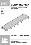
GUIDA TECNICA
User’s Manual - Technische Anleitung
Guide Technique
Bedienungsanweisung
Montage
Wartung
Utilisation
Assemblage
Entretien
Retrobanchi
MEMPHIS
RetroMemphis210405
Back Counters MEMPHIS
Rückentheken MEMPHIS
Arrière-comptoirs MEMPHIS
ISTRUZIONI DI MONTAGGIO
RETROALZATE MEMPHIS
MEMPHIS RISERS FOR BACK COUNTER UNITS
ASSEMBLY ISTRUCTIONS
MONTAGEANWEISUNGEN RÜCKENAUFSÄTZE MEMPHIS
INSTRUCTIONS DE MONTAGE
ELEMENTS HAUTS ARRIERE-COMPTOIRS MEMPHIS
Pag.1
Fase 1
Togliere le strisce di scorrimento in legno.
Remove the wood sliding strips.
Die Holzgleitstreifen abnehmen.
Retirer les poutrelles de coulissement en bois.
Fase 2
Montare i piedini.
Apply feet.
Die Füße montieren.
Monter les pieds.
Pag.2
Fase 3
Fissare i montanti alle basi usando le viti in dotazione (M8x14 fondo, autofilettanti 4x25 a legno per piano lavoro).
Attach the vertical uprights to the base unit using the supplied screws (M8x14 bottom, 4x25 self-tapping for wood
worktop).
Die Ständer mit den zur Ausstattung gehörenden Schrauben an den Basiselementen befestigen (M8x14 Boden,
selbstschneidend 4x25 für Holz für Arbeitsfläche).
Fixer les montants sur les bases à l'aide des vis fournies en dotation (M8x14 fond, vis-taraud 4x25 en bois pour
plan de travail)
Pag.3
Fase 4
Accostare le basi al muro e livellarle agendo sui piedini regolabili
(vedi Fig.1)
Place the base units against the wall and level using the
adjustable feet (see Fig.1)
Die Basiselemente der Wand nähern und sie ausrichten, indem
man auf die verstellbaren Füße einwirkt (man sehe Abb.1).
Positionner les bases contre le mur et les mettre à niveau en
agissant sur les pieds réglables (voir Fig.1)
Pag.4
Fig.1
Fase 5
Collegare le basi usando le viti in dotazione.
Connect the base units using the supplied screws.
Die Basiselemente mit den zur Ausstattung gehörenden Schrauben verbinden.
Unir les bases entre elles à l'aide des vis fournies en dotation.
Fase 6
Fissare eventualmente al muro i montanti usando tappi ad espansione (sufficiente n°1 tappo per montante).
Attach the vertical uprights to the wall, if necessary, using expansion screws (1 expansion screw per vertical
upright is sufficient).
Die Ständer eventuell an der Wand befestigen, indem man Spreizverschlüsse verwendet (Nr.1 Verschluss pro
Ständer ist ausreichend)
Fixer éventuellement les montants au mur à l'aide de chevilles à expansion (1 cheville par montant suffit).
Pag.5
Fig.1
Fase 7
6mm
Appoggiare il top in acciaio inox sul piano della base,
facendo attenzione a posizionarlo a 6mm dai montanti
posteriori come indicato in Fig.1, nel caso in cui fosse un
top in granito posizionarlo a 12mm dai montanti come
indicato in Fig.2.
Rest the stainless steel top on the base unit, being
careful to position it 6mm from the rear uprights, as
shown in Fig.1; in the case of a granite top, position it
12mm from vertical uprights as shown in Fig.2.
12mm
Fig.2
Das Top aus rostfreiem Stahl auf die Platte des
Basiselements legen, dabei darauf achten, dass es wie
in Abb.1 angezeigt 6 mm Abstand zu den hinteren
Ständern hat, sollte es sich um ein Top aus Granit
handeln, muss es 12 mm von den Ständern entfernt
sein, wie aus Abb.2 ersichtlich ist.
Poser le plan en acier inox sur la surface de la base, en
laissant une distance de 6 mm par rapport aux montants
arrière, comme indiqué en Fig. 1 ; si le plan est en granit,
placez-le à une distance de 12 mm des montants,
comme indiqué en Fig.2.
Fase 8
Fissare il piano inox dall’interno della base,
utilizzando viti per legno 4x30 vedi Fig.3, nel caso
di top in granito, fissare il piano alle basi mediante
silicone non acetico.
Fig.3
Attach the stainless steel top from the inside of
the base unit, using wood screws 4x30, see Fig.3;
in the case of a granite top, attach it to base unit
using non-acetic silicone.
Die rostfreie Stahlplatte vom Inneren der Basis
aus befestigen, hierbei Schrauben für Holz 4x30
verwenden, man sehe Abb.3, bei Granittops muss
die Platte mit nicht essighaltigem Silikon an der
Basis befestigt werden.
Fixer le plan en acier inox à partir de l'intérieur de
la base, à l'aide de vis pour bois 4x30 (voir Fig.3);
pour le plan en granit, fixer le plan sur les bases
en utilisant du silicone non acétique.
Pag.6
Fase 9
Fig.1
Agganciare lo schienale inferiore, mediante i piastrini premontati sullo stesso, nelle apposite aperture
poste sui montanti facendo in modo che lo schienale appoggi sull’alzatina del top (Vedi Fig.1).
Using the pre-mounted plates, hook the lower back panel onto the appropriate openings on the vertical
uprights, so that the back panel rests on the top splash raiser (See Fig.1).
Das untere Rückenelement mit den auf ihm vormontierten Plättchen in die vorgesehenen Öffnungen auf
den Ständern einhaken, dabei muss das Rückenelement auf dem Aufsatz des Tops anliegen. (Man sehe
Abb.1).
Fixer le panneau arrière inférieur à l'aide des plaquettes prédisposées sur ce dernier, en les enclenchant
sur les montants de façon à ce que le panneau repose sur le dosseret du plan (Voir Fig.1).
Pag.7
Fig.1
Fase 10
Inserire n°2 piastrini (uno per lato) nell’apposita sede posta
nella parte posteriore dell’estruso di alluminio (Vedi Fig.1),
procedere all’aggancio dell’estruso ai montanti, facendo
attenzione che ci sia il corretto accoppiamento tra estruso e
schienale (vedi Fig.2).
Insert 2 plates (one on each side) into the appropriate hole
on the back of the aluminium profile (See Fig.1), proceed
with hooking the aluminium profile to the vertical uprights,
making sure that the extruded aluminium and the back panel
match correctly (see Fig.2).
Nr.2 Plättchen (eines pro Seite) in den vorgesehenen Sitz auf
dem unteren Abschnitt des Strangpress- Aluminiumteils
einfügen (man sehe Abb.1). Zum Einhaken des
Strangpressteils in die Ständer übergehen, dabei darauf
achten, dass die Verbindung zwischen Strangpressteil und
Rückenelement korrekt ist (man sehe Abb.2).
Introduire n°2 plaquettes (une de chaque côté) dans
l'emplacement situé sur la partie arrière du profil en
aluminium (voir Fig.1), puis fixer le profil aux montants de
façon à obtenir un accouplement parfait entre le profil et le
panneau arrière (voir Fig.2).
Fase 11
Fig.2
Inserire lo schienale centrale nella sede dell’estruso in
alluminio come indicato in Fig.2.
Insert the centre back panel into the groove of the
aluminium profile as shown in Fig.2.
Das zentrale Rückenelement in den Sitz des
Strangpress- Aluminiumteils einsetzen, wie in Abb.2
gezeigt.
Installer le panneau arrière central en l'encastrant dans
l'emplacement du profil en aluminium, comme indiqué
en Fig.2.
Pag.8
Fase 12
Proseguire con il montaggio dell’estruso di alluminio e dello schienale superiore seguendo le descrizioni riportate
nella FASE 10 e FASE 11.
Continue with the application of the aluminium profile and the upper back panel, following the description given in
STEPS 10 and 11.
Mit der Montage des Strangpress-Aluminiumteils und des oberen Rückenelements fortfahren, indem man den
Beschreibungen unter PHASE 10 und PHASE 11 folgt.
Procéder à l'installation du profil d'aluminium et du panneau arrière supérieur en suivant les descriptions
reportées en PHASE 10 et en PHASE 11.
Fig.2
Fig.1
Fase 13
Agganciare l’estruso superiore elettrificato già provvisto di
cornice (Vedi Fig.1 e Fig.2), come descritto nella FASE 10.
Hook the upper, electrically wired aluminium profile complete
with frame (See Figs.1 and 2), as described in STEP 10.
Das obere elektrifizierte Strangpressteil, welches schon mit
Rahmen versehen ist (man sehe Abb.1 und 2) einhaken wie
unter PHASE 10 beschrieben.
Fixer le profil supérieur électrifié, déjà muni de l'encadrement
(voir Fig.1 et fig.2), comme décrit en PHASE 10.
Pag.9
Fase 14
Fig.1
Nel caso ci sia la necessità di canalizzare due o più estrusi, utilizzare i piastrini forniti in dotazione,
come indicato in Fig.1
If it is necessary to channel one or more profiles, use the plates supplied standard as shown in Fig.1.
Sollte es notwendig sein zwei oder mehrere Strangpressteile zu kanalisieren, die zur Ausstattung gehörenden
Plättchen verwenden, wie in Abb.1 gezeigt.
En cas de nécessité d'unir deux ou plusieurs profils, utiliser les plaquettes fournies en dotation, comme indiqué
en Fig.1.
Fase 15
Fissare l’estruso inferiore e centrale ai montanti, mediante
viti autofilettanti fornite in dotazione.
Attach the lower and centre profiles to the vertical uprights
using the supplied self-tapping screws.
Das untere und das zentrale Strangpressteil an den
Ständern mittels selbstschneidender Schrauben
befestigen, die in der Ausstattung enthalten sind.
Fixer le profil inférieur et central aux montants, à l'aide des
vis-taraud fournies en dotation.
Pag.10
Fase 16
A questo punto è possibile effettuare il collegamento elettrico alla rete (vedi Fig.1) utilizzando appositi
trasformatori a 12 Volt (non forniti in dotazione).
N.B.
I collegamenti elettrici vanno fatti usufruendo dell’intercapedine che si ha tra il muro e lo schienale.
Il cablaggio dei componenti elettrici del relativo impianto di illuminazione deve essere effettuato da personale
autorizzato. L’applicazione delle vigenti norme di sicurezza e messa a terra è demandato all’installatore,
unitamente alle relative responsabilità.
Now the electrical connections to the mains can be made (see Fig.1), using appropriate 12 volt transformers
(not supplied).
N.B.
The electrical connections must be set in the gap between the wall and the back panel.
The wiring of the electrical components and the relative lighting system must be carried out by qualified
technicians.The installer is obliged to observe current safety norms and to earth the system properly under his/her
own responsibility.
Nunmehr kann der elektrische Anschluss an das Netz vorgenommen werden (man sehe Abb.1), wobei eigens
vorgesehene 12 Volt Trafos eingesetzt werden (diese werden nicht mit der Ausstattung geliefert).
N.B.
Die elektrischen Anschlüsse werden gemacht, indem man den Zwischenraum ausnutzt, der zwischen der Wand
und dem Rücken besteht. Die Verkabelung der elektrischen Bestandteile der jeweiligen Beleuchtungsanlage
muss von autorisiertem Personal ausgeführt werden. Die Anwendung der geltenden Sicherheitsvorschriften und
die Vererdung obliegen dem Installateur, welcher die jeweiligen Verantwortlichkeiten trägt.
Il est possible maintenant d'effectuer le branchement électrique au réseau (voir Fig.1) en utilisant les
transformateurs à 12 Volts (non fournis en dotation).
N.B.
Les connexions électriques doivent être effectuées en tirant partie de l'espace vide entre le mur et le panneau
arrière. Le câblage des composants électriques de l'installation d'éclairage doit être effectué par un technicien
autorisé. Le respect des normes de sécurité en vigueur et de la mise à la terre incombe à l'installateur, ainsi que
les responsabilités afférentes.
Pag.11
Fase 17
Inserire la parte terminale del faretto nell’apposita sede
dell’estruso in alluminio (Vedi Fig.1).
Insert the end of the spot light in the proper hole of the
aluminium profile (See Fig.1).
Fig.1
Den Endteil des Strahlers in den vorgesehenen Sitz auf
dem Strangpress-Aluminiumteil einsetzen (man sehe
Abb.1).
Introduire la partie finale du spot dans l'emplacement situé
sur le profil en aluminium (voir Fig.1).
Fase 18
Fig.2
Premendo la base del faretto contro l’estruso, avvitare le
due viti esterne “A” (Vedi Fig.3) tenendo il cacciavite
inclinato come l’asse della vite (Vedi Fig.2). SOLO nel
caso di mancata accensione della lampada avvitare
delicatamente le due viti “B”, nel caso in cui il problema
persista, procedere con l’eliminazione graduale delle
rondelle poste sotto le viti “B”.
Press the base of the spot light against the profile, tighten
the two external “A” screws (See Fig.3), keeping the
screwdriver slanted at the same angle as the axis of the
screw (See Fig.2). If the light bulb does not light, and in
this case ONLY, delicately tighten the two “B” screws,if
the problem continues, gradually eliminate (one by one)
the washers under screws B.
Fig.3
Indem man die Basis des Strahlers gegen das
Strangpressteil drückt, die beiden externen Schrauben
“A“ anschrauben (man sehe Abb.3) , den
Schraubenzieher entsprechend der Schraubenachse
geneigt halten (man sehe Abb.2). NUR im Fall einer nicht
erfolgten Einschaltung der Lampe die beiden Schrauben
“B“ vorsichtig anschrauben,Sollte das Problem weiterhin
bestehen, zur graduellen Elimination der Scheiben unter
den Schrauben "B" übergehen.
A
B
En appuyant la base du spot contre le profil, visser les
deux vis externes “A” (voir Fig.3) en gardant le tournevis
incliné comme l'axe de la vis (voir Fig.2). UNIQUEMENT
dans le cas où la lampe ne s'allume pas, visser
délicatement les deux vis “B”,Si le problème persiste,
procéder à l'élimination graduelle des rondelles sous les
vis B.
Fig.4
Fase 19
Fare scorrere la copertura decorativa come indicato in Fig.4
Slide the decorative cover as shown in Fig.4
Die Dekorabdeckung wie in Abb.4 gezeigt, gleiten lassen.
Faire glisser le petit cache décoratif, comme indiqué en Fig.4.
Pag.12
Fig.1
Fase 20
Inserire negli estrusi, alla distanza desiderata, i reggi
mensole (Vedi Fig.1).
Insert the shelf brackets into the aluminium profile at the
desired intervals (See Fig.1).
In die Strangpressteile die Regalhalter in den
gewünschten Abständen einsetzen (man sehe Abb.1).
Enclencher sur les profils, à la hauteur souhaitée, les
supports à étagères (voir Fig.1).
Fase 21
Appoggiare le mensole in vetro sui rispettivi supporti.
Rest the glass shelves on the brackets.
Die Glasregale auf den jeweiligen Halterungen
positionieren.
Poser les étagères en verre sur ses supports respectifs.
Pag.13
Fase 22
Montare le fiancate terminali in lamiera verniciata, fissando il tutto mediante viti fornite in dotazione.
Assemble the painted sheet metal end sides, using the supplied screws to attach them all.
Die Endseiten aus gestrichenem Blech montieren, indem die Befestigung mittels der zur Ausstattung gehörenden
schrauben ausgeführt wird.
Monter les joues latérales de finition en tôle peinte, en fixant le tout à l'aide des vis fournies en dotation.
Pag.14
ISTRUZIONI DI MONTAGGIO
RETROBANCHI AD ANGOLO
BASE PIU’ALZATA
ASSEMBLY INSTRUCTIONS FOR BACK COUNTER CORNERS,
BASE WITH RISER
MONTAGEANWEISUNGEN FÜR ECKIGE RÜCKENTHEKEN,
BASISELEMENT MIT AUFSATZ
INSTRUCTIONS DE MONTAGE POUR ARRIERE-COMPTOIRS
ANGULAIRES,
BASE AVEC ELEMENT HAUT
Pag.15
ATTENZIONE:
In una composizione di retrobanchi, gli elementi ad angolo vanno sempre posizionati prima dei lineari, avendo
cura di inserirli esattamente in corrispondenza dell’angolo, lasciando tra la base e la parete la misura indicata a
disegno.
ATTENTION:
In a composition of back counter units, the corner units must always be positioned before the linear units, being
careful to insert them in exact correspondence to the corner, leaving the distance indicated in the drawing
between the base unit and the wall.
ACHTUNG:
Bei einer Rückenthekenkomposition müssen die eckigen Elemente immer vor den geraden Elementen
positioniert werden, dabei darauf achten, dass sie genau in Übereinstimmung mit der Ecke eingefügt werden,
wobei zwischen der Basis und der Wand der in der Zeichnung angegebene Abstand bestehen muss.
ATTENTION :
Dans une composition d'arrière-comptoirs, les modules angulaires doivent toujours être positionnés avant les
modules linéaires, en faisant attention de les placer exactement en correspondance de l'angle, et en laissant
entre la base et la paroi l'espace indiqué dans le schéma.
DIMENSIONI IN PIANTA: / PROJECT DIMENSIONS: / ABMESSUNGEN: / DIMENSIONS SUR PLAN :
30 mm
400/630 mm
BASE - ALZATA A45°:
400/630 mm
BASE - ALZATA A90°:
Per le istruzioni di montaggio seguire da
FASE1 a FASE6 le istruzioni di montaggio dei
Retrobanchi LINEARI.
For assembly instructions, follow the
instructions for assembling the LINEAR back
counter units from Step 1 to Step 6.
400/630 mm
Hinsichtlich der Montage die PHASEN 1 bis 6
der Montageanleitungen der GERADEN
Rückentheken befolgen.
Pour le montage, suivre les instructions de
montage des arrière-comptoirs LINEAIRES,
de la PHASE 1 à la PHASE 6.
BASE - ALZATA B45°:
Pag.16
BASE - ALZATA ANGOLO B90°
ATTENZIONE;
Questo tipo di retrobanco, base più alzata B90°, va assemblato prima di essere accostato alla parete.
BASE UNIT CORNER RISER B90°
ATTENTION;
This type of back counter unit, base unit + riser B90°, must be assembled before being moved against the wall.
BASIS-AUFSATZ ECKE B90°
ACHTUNG:
Diese Art Rückentheke, Basis plus Aufsatz B90°, muss vor dem Anrücken an die Wand zusammengebaut werden.
BASE ELEMENT HAUT ANGULAIRE B90°
ATTENTION :
Ce type d'arrière-comptoir (base avec élément haut B90°) doit être assemblé avant d'être placé contre la paroi.
DIMENSIONI IN PIANTA: / PROJECT DIMENSIONS: / ABMESSUNGEN: / DIMENSIONS SUR PLAN :
C
30 mm
30 mm
D
400/630 mm
B
A
Fase 1
Per il montaggio della base “A” vedi da FASE1 a FASE3 delle istruzioni di montaggio dei retrobanchi LINEARI.
To assemble base unit “A”, see instructions for assembling LINEAR back counter units Step 1 to Step 3
Zur Montage des Basiselements „A“ sehe man PHASE 1 bis PHASE 3 der Montageanleitungen der geraden
Rückentheken.
Pour le montage de la base « A », suivre les instructions de montage des arrière-comptoirs LINEAIRES, de la
PHASE 1 à la PHASE 3.
Pag.17
Fase 2
Fissare il montante “B” alla parte posteriore della base utilizzando le viti fornite in dotazione.
N.B: Il montante è già completo di elemento estetico di copertura (Inox, lamiera verniciata, legno massello) che
caratterizza i vari modelli.
Attach upright “B” to the back of the base unit using the supplied screws.
N.B.: the vertical upright is already supplied with the decorative covering (stainless steel, painted sheet metal,
solid wood trim) which characterises the various models.
Den Ständer „B“ an dem hinteren Teil des Basiselements montieren, hierzu die zur Ausstattung gehörenden
Schrauben verwenden.
N.B.: Der Ständer ist schon komplett mit dem ästhetischem Abdeckungselement (rostfreier Stahl, lackiertes
Blech, Massivholz), welches die verschiedenen Modelle charakterisiert.
Fixer le montant « B » sur la partie arrière de la base à l'aide des vis fournies en dotation.
N.B.: Le montant est déjà équipé de l'élément décoratif de revêtement (inox, tôle peinte, bois massif) qui
caractérise les différents modèles.
Fase 3
Montare l’elemento cielino di raccordo “C” dove previsto.
Assemble the top element of joint “C”, where present.
Das Deckenverbindungselement “C“ wo vorgesehen montieren.
Monter l'élément plafonnier de raccord “C” à l'endroit prévu.
Fase 4
Accostare il retrobanco così assemblato, allo spigolo della parete.
Once assembled, move the back counter unit against the corner of the wall.
Die somit zusammengebaute Rückentheke an die Ecke der Wand rücken.
Positionner l'arrière-comptoir ainsi assemblé contre l'angle de la paroi.
Fase 5
Procedere alla canalizzazione con eventuali basi e alzate adiacenti, come indicato nelle FASI 4 e 5 delle istruzioni
di montaggio dei retrobanchi LINEARI.
Proceed with channelling to any other adjacent bases and risers, as shown in STEPS 4 and 5 of the assembly
instructions for LINEAR back counter units.
Die Kanalisierung mit eventuellen Basiselementen und anliegenden Aufsätzen ausführen, wie es in der PHASE 4
und 5 der Montageanleitungen der GERADEN Rückentheken beschrieben ist.
Procéder à l'assemblage avec les autres bases et éléments hauts adjacents, comme indiqué aux PHASES 4 et 5
des instructions de montage des arrière-comptoirs LINEAIRES.
Pag.18
Fase 6
Montare le mensole in vetro, dove previsto.
Install the glass shelves, where present.
Die Glasregale, wo vorgesehen, montieren.
Monter les étagères en verre, à l'endroit prévu.
ATTENZIONE:
C
ATTENTION:
ACHTUNG:
D
ATTENTION :
B
A
Quando il retrobanco B90° è posizionato a fine composizione, va accostato direttamente alla parete, provocando
un allontanamento dal muro di tutti gli altri retrobanchi ad esso accostati.
When back counter unit B90° is positioned at the end of a composition, it must be placed directly against the wall,
moving all of the other back counter units away from the wall.
Wenn die Rückentheke B90° am Ende der Komposition positioniert ist, muss sie direkt an die Wand kommen,
dies bewirkt, dass alle mit ihr kombinierten Rückentheken weiter von der Wand entfernt sind.
Si l'arrière-comptoir B90° est positionné en fin de composition, il doit être placé directement contre la paroi, en
provoquant l'éloignement du mur de tous les autres arrière-comptoirs assemblés à ce dernier.
Pag.19
ISTRUZIONI DI MONTAGGIO
RETRO MACCHINA CAFFE’/ SNACK
MEMPHIS
BACK COUNTER UNITS FOR COFFEE MACHINE/SNACK
MEMPHIS
MONTAGEANWEISUNGEN KAFFEEMASCHINE- UND SNACKRÜCKENAUFSÄTZE MEMPHIS
INSTRUCTIONS DE MONTAGE
ARRIERE-COMPTOIR POUR MACHINE A CAFE / SNACK
MEMPHIS
RETRO MACCHINA CAFFE’
RETRO SNACK
Pag.20
Fase 1
Togliere le strisce di scorrimento in legno,montare piedini regolabili e montanti come descritto nelle FASI 1,
2 e 3, nelle istruzioni di montaggio delle alzate.
Remove the wood sliding strips, assemble the adjustable feet and vertical uprights as described in STEPS 1,
2 and 3 in the instructions for assembling the risers.
Wie in den PHASEN 1,2 und 3 der Montageanleitung der Aufsätze beschrieben, die Gleitstreifen aus Holz
abnehmen und die verstellbaren Füße und Ständer installieren.
Retirer les poutrelles de coulissement en bois, monter les pieds réglables et les montants comme indiqué
dans les PHASES 1, 2 et 3 des instructions de montage des éléments hauts.
Fase 2
Montare lo schienale rivestito inox, agganciandolo ai montanti per mezzo dei piastrini premontati (vedi descrizione
FASE 9 istruzioni retro alzate) come indicato in Fig.1.
Assemble the stainless steel covered back panel, hooking it onto the vertical uprights with the pre-mounted plates
(see description STEP 9 back riser instructions) as shown in Fig.1.
Die mit rostfreiem Stahl verkleidete Rückseite montieren, indem sie wie in Abb. 1 ersichtlich, mittels der
vormontierten Plättchen in die Ständer gehakt wird (man sehe Beschreibung der PHASE 9 der Anleitungen zu den
Aufsatzrücken).
Monter le panneau arrière revêtu d'acier inox, en l'enclenchant sur les montants à l'aide des plaquettes
prédisposées (voir description PHASE 9 instructions éléments hauts arrière-comptoir) comme indiqué en Fig.1.
Fig.1
Pag.21
Fase 3
Agganciare l’estruso superiore seguendo le istruzioni riportate nella FASE13 delle istruzioni di montaggio delle
alzate.
Hook on the upper profile following the instructions given in STEP 13 of the riser assembling instructions.
Das obere Strangpressteil einhaken, dabei die Anleitungen befolgen, die unter PHASE 13 der Montageanleitungen
der Aufsätze gegeben wurden.
Fixer le profil supérieur en suivant les instructions reportées dans la PHASE 13 des instructions de montage des
éléments hauts.
Fase 4
Canalizzare il retro Macchina caffè o Snack con le altre basi della composizione come descritto nelle istruzioni di
montaggio delle alzate nella FASE 5, con l’accorgimento di fare accoppiare l’estruso superiore di alluminio
mediante l’utilizzo di un piastrino fornito in dotazione (vedi FASE 14 istruzioni retro alzate).
Channel the Coffee Machine or Snack back counter unit with the other base units of the composition as described
in the instructions for assembling the risers in STEP 5, being careful to couple the upper aluminium profile using
one of the supplied plates (see STEP 14 of the back riser instructions).
Das Kaffeemaschinen oder Snack Rückenelement mit den anderen Basen der Komposition kanalisieren, wie es in
der PHASE 5 der Montageanleitungen der Aufsätze beschrieben ist. Hierbei auf die Verbindung des oberen
Strangpress-Aluminiumteils mittels des Einsatzes eines der zur Ausstattung gehörenden Plättchen achten (man
sehe PHASE 14 der Anleitungen Aufsatzrücken).
Assembler l'arrière-comptoir Machine à café ou Snack avec les autres bases de la composition, comme indiqué
dans les instructions de montage des éléments hauts à la PHASE 5, en accouplant le profil supérieur en aluminium
à l'aide de la plaquette fournie en dotation (voir PHASE 14 des instructions de montage des éléments hauts de
l'arrière-comptoir).
Fase 5
Nel caso del retro SNACK, provvedere al montaggio del piano top inox come descritto nelle FASI 7 e 8 delle
istruzioni di montaggio delle alzate.
For the SNACK back counter unit, assemble the stainless steel top as described in STEPS 7 and 8 of the riser
assembly instructions.
Im Fall des SNACK Rückenelements für die Montage des Tops aus rostfreiem Stahl sorgen, wie es unter den
PHASEN 7 und 8 der Montageanleitungen der Aufsätze beschrieben ist.
Pour l'arrière-comptoir SNACK, procéder au montage du plan en acier inox comme indiqué aux PHASES 7 et 8 des
instructions de montage des éléments hauts.
Pag.22
Fase 6
Fig.1
A
Fig.2
B
Agganciare la cappa all’apposito supporto “A”, premontato sullo schienale (vedi Fig.1), mediante il profilo
posteriore “B” (vedi Fig.2)
Hook the hood to the appropriate support “A” which is pre-assembled to the back panel (see Fig.1), using the
rear profile “B” (see Fig.2).
Die Haube in die vorgesehene Halterung “A“, welche auf der Rückseite vormontiert ist (man sehe Abb.1)
einhaken, dies mittels des hinteren Profils “B“ (man sehe Abb.2).
Fixer la hotte sur le support “A” prédisposé sur le panneau arrière (voir Fig.1), à l'aide du profil arrière “B”
(voir Fig.2)
Pag.23
Fase 7
Effettuare il cablaggio della cappa alla rete elettrica.
N.B.
I collegamenti elettrici vanno fatti usufruendo dell’intercapedine che si ha tra il muro e lo schienale.Il cablaggio dei
componenti elettrici del relativo impianto di illuminazione deve essere effettuato da personale autorizzato.
L’applicazione delle vigenti norme di sicurezza e messa a terra è demandato all’installatore, unitamente alle
relative responsabilità.
Wire the hood to the electric mains.
N.B.
The electrical connections must be set in the gap between the wall and the back panel.
The wiring of the electrical components and the relative lighting system must be carried out by qualified
technicians.The installer is obliged to observe current safety norms and to earth the system properly under his/her
own responsibility.
Die Verkabelung der Haube an das elektrische Netz vornehmen.
N.B.
Die elektrischen Anschlüsse werden gemacht, indem man den Zwischenraum ausnutzt, der zwischen der Wand
und dem Rücken besteht. Die Verkabelung der elektrischen Bestandteile der jeweiligen Beleuchtungsanlage
muss von autorisiertem Personal ausgeführt werden. Die Anwendung der geltenden Sicherheitsvorschriften und
die Vererdung obliegen dem Installateur, welcher die jeweiligen Verantwortlichkeiten trägt.
Effectuer le câblage de la hotte au réseau électrique.
N.B.
Les connexions électriques doivent être effectuées en tirant partie de l'espace vide entre le mur et le panneau
arrière. Le câblage des composants électriques de l'installation d'éclairage doit être effectué par un technicien
autorisé. Le respect des normes de sécurité en vigueur et de la mise à la terre incombe à l'installateur, ainsi que
les responsabilités afférentes.
Pag.24
Fase 8
Montare fianchi terminali su base e alzata, come descritto nella FASE 22 delle istruzioni di montaggio delle alzate.
Assemble the end sides on the base unit and riser as described in STEP 22 of the riser assembly instructions.
Die Abschlussseiten auf dem Basiselement und dem Aufsatz montieren, wie es in PHASE 22 der
Montageanleitungen der Aufsätze beschrieben ist.
Monter les joues de finition sur la base et l'élément haut, comme indiqué à la PHASE 22 des instructions de
montage des éléments hauts.
Pag.25
ISTRUZIONI DI MONTAGGIO
RETRO TABACCHI MEMPHIS
MEMPHIS TOBACCO PRODUCT RISERS FOR BACK COUNTER
UNITS
ASSEMBLY ISTRUCTIONS
MONTAGEANWEISUNGEN RÜCKENAUFSÄTZE TABAKWAREN
MEMPHIS
INSTRUCTIONS DE MONTAGE
ARRIERE-COMPTOIR A TABAC MEMPHIS
Pag.26
Fase 1
Per l’installazione della base retro Tabacchi, procedere come indicato nelle istruzioni di montaggio delle
alzate, da FASE 1 a FASE 8.
To install the Tobacco product back base, proceed as indicated in the riser assembly instructions from
STEPS 1 to 8.
Zur Installation des Rückenbasiselements Tabakwaren genauso vorgehen, wie es in der Montageanleitung
der Aufsätze von PHASE 1 bis 8 beschrieben ist.
Pour l'installation de la base de l'arrière-comptoir à tabac, procéder comme indiqué dans les instructions de
montage des éléments hauts, de la PHASE 1 à la PHASE 8.
Fase 2
Montare lo schienale centrale e laterale, come indicato
in Fig.1, utilizzando n°12 viti 3.5x16 fornite in dotazione.
Assemble the centre and side back panels as shown in
Fig.1, using 12 of the supplied 3.5x16 screws.
Den zentralen und seitlichen Rücken montieren, wie in
Abb.1 gezeigt, hierbei Nr.12 der zur Ausstattung
gehörenden Schrauben 3.5x16 verwenden.
Monter le panneau arrière central et latéral, comme
indiqué en Fig.1, à l'aide des 12 vis 3.5x16 fournies en
dotation.
Pag.27
Fig.1
Fase 3
Agganciare l’estruso elettrificato superiore seguendo le istruzioni riportate nella FASE13 delle istruzioni di
montaggio delle alzate.
Hook the electrically wired upper profile, following the instructions given in STEP 13 of the riser assembly
instructions.
Das elektrifizierte obere Strangpressteil einhaken, indem man die Anleitungen unter der PHASE 13 der
Montageanleitungen der Aufsätze befolgt.
Fixer le profil supérieur électrifié en suivant les instructions reportées à la PHASE 13 des instructions de montage
des éléments hauts.
Fase 4
Eseguire ora il collegamento elettrico alla rete e il montaggio dei faretti, come visto nelle istruzioni di montaggio
delle alzate da FASE16 a FASE19 utilizzando appositi trasformatori a 12 Volt (non forniti in dotazione).
N.B.
I collegamenti elettrici vanno fatti usufruendo dell’intercapedine che si ha tra il muro e lo schienale.
Il cablaggio dei componenti elettrici del relativo impianto di illuminazione deve essere effettuato da personale
autorizzato.L’applicazione delle vigenti norme di sicurezza e messa a terra è demandato all’installatore,
unitamente alle relative responsabilità.
Now, make the electrical connections to the mains and assemble the spot lights, as shown in the riser assembly
instructions from STEPS 16 to 19, using appropriate 12 volt transformers (not supplied).
N.B.
The electrical connections must be set in the gap between the wall and the back panel.
The wiring of the electrical components and the relative lighting system must be carried out by qualified
technicians.The installer is obliged to observe current safety norms and to earth the system properly under his/her
own responsibility.
Nun den elektrischen Anschluss an das Stromnetz und die Montage der Strahler ausführen, wie schon in den
Montageanleitungen der Aufsätze unter PHASE 16-19 gesehen, hierbei die vorgesehenen 12 Volt Trafos
verwenden (sie werden nicht mit der Ausstattung geliefert).
N.B.
Die elektrischen Anschlüsse werden gemacht, indem man den Zwischenraum ausnutzt, der zwischen der Wand
und dem Rücken besteht. Die Verkabelung der elektrischen Bestandteile der jeweiligen Beleuchtungsanlage
muss von autorisiertem Personal ausgeführt werden. Die Anwendung der geltenden Sicherheitsvorschriften und
die Vererdung obliegen dem Installateur, welcher die jeweiligen Verantwortlichkeiten trägt.
Effectuer le branchement électrique au réseau ainsi que le montage des spots d'éclairage, comme déjà indiqué
dans les instructions de montage des éléments hauts, de la PHASE 16 à la PHASE 19, en utilisant les
transformateurs à 12 Volts (non fournis en dotation).
N.B.
Les connexions électriques doivent être effectuées en tirant partie de l'espace vide entre le mur et le panneau
arrière. Le câblage des composants électriques de l'installation d'éclairage doit être effectué par un technicien
autorisé. Le respect des normes de sécurité en vigueur et de la mise à la terre incombe à l'installateur, ainsi que
les responsabilités afférentes.
Pag.28
Fase 5
Fig.1
Montare i profili porta vetro di contenimento su mensola, mediante vite a canocchiale M4, come indicato in Fig.1
Assemble the glass containing support profiles on the shelf, using the telescope screw M4 as shown in Fig.1.
Auf dem Regal die Halterungsprofile des Einfass-Glases wie in Abb.1 gezeigt mit M4 Schrauben montieren.
Monter les tasseaux porte-vitre sur l'étagère à l'aide des vis M4, comme indiqué en Fig.1
Pag.29
Fase 6
Fig.1
Inserire i braccetti divisori su mensola come indicato in Fig.1
Insert the divider wires on the shelf as shown in Fig.1
Wie in Abb.1 gezeigt die Regalunterteilungen einfügen.
Introduire les petits bras de séparation sur l'étagère comme indiqué en Fig.1
Fase 7
Fig.2
Agganciare sulla cremagliera ( vedi Fig.2) nella posizione desiderata, le tre mensole.
Hook the three shelves onto the rack in the required position (see fig. 2).
Auf der Zahnstange (man sehe Abb.2) drei Regale in der gewünschten Position einhaken.
Fixer les trois étagères sur la crémaillère (voir Fig.2) sur la position souhaitée.
Pag.30
Fase 8
Fig.1
Inserire i vetri di contenimento negli appositi supporti
precedentemente montati, come indicato in Fig.1
Insert the containing glass into the appropriate previously
assembled supports, as shown in Fig.1
Die Einfass-Gläser in die vorher montierten vorgesehenen
Halterungen einsetzen, wie in Abb.1 gezeigt.
Introduire les vitres frontales dans les supports précédemment
installés, comme indiqué en Fig.1
Fase 9
Montare fianchi terminali su base e alzata, come descritto nella FASE 22 delle istruzioni di montaggio delle alzate.
Assemble the end sides on the base unit and riser, as described in STEP 22 of the riser assembly instructions.
Die Abschluss-Seiten auf Basis und Aufsatz montieren, wie in der PHASE 22 der Montageanleitungen der Aufsätze
beschrieben.
Monter les joues de finitions sur la base et sur l'élément haut, comme indiqué à la PHASE 22 des instructions de
montage des éléments hauts.
Pag.31
ISTRUZIONI DI MONTAGGIO
RETRO VETRINA PENSILE REFRIGERATA
MEMPHIS
MEMPHIS REFRIGERATED HANGING GLASS CASE BACK
ASSEMBLY ISTRUCTIONS
MONTAGEANLEITUNGEN GEKÜHLTE RÜCKENHÄNGEVITRINE
MEMPHIS
INSTRUCTIONS DE MONTAGE
VITRINE ARRIERE MURALE REFRIGEREE MEMPHIS
Pag.32
Fase 1
Togliere le strisce di scorrimento in legno, montare piedini regolabili e n°4 montanti (vedi Fig.1) seguendo le
FASI 1, 2 e 3, nelle istruzioni di montaggio delle alzate.
Remove the wood sliding strips, apply the adjustable feet and 4 vertical uprights (see Fig.1), following
STEPS 1, 2 and 3 in the riser assembly instructions.
Die Holzgleitstreifen abnehmen, die verstellbaren Füße und Nr.4 Ständer montieren (man sehe Abb.1),
hierbei die PHASEN 1,2 und 3 der Montageanleitungen für die Aufsätze befolgen.
Retirer les poutrelles de coulissement en bois, monter les pieds réglables et les 4 montants (voir Fig.1) en
suivant les PHASES 1, 2 et 3 des instructions de montage des éléments hauts.
Fase 2
Montare lo schienale rivestito inox, agganciando il
profilo posteriore ai montanti e fissare il tutto con n° 12
viti 4.2x16 come indicato in Fig.1.
Fig.1
Assemble the stainless steel covered back panel,
hooking the rear profile to the vertical uprights, and
attach everything using 12 of the 4.2x16 screws as
shown in Fig.1.
Den mit rostfreiem Stahl verkleideten Rücken
montieren, indem das hintere Profil in die Ständer
gehakt wird und das Ganze mit Nr. 12 Schrauben
4.2x16 befestigen, wie in Abb.1 angezeigt.
Monter le panneau arrière revêtu d'acier inox, en
enclenchant le profil arrière sur les montants, et fixer le
tout à l'aide des 12 vis 4.2x16 comme indiqué en Fig.1.
Fase 3
Agganciare l’estruso superiore seguendo le istruzioni riportate nella FASE13 delle istruzioni di montaggio delle
alzate.
Hook the upper profile following the instructions in STEP 13 of the riser assembly instructions.
Das obere Strangpressteil einhaken, dabei die Anleitungen in der PHASE 13 der Montageanleitungen der Aufsätze
befolgen.
Fixer le profil supérieur en suivant les instructions reportées en PHASE 13 des instructions de montage des
éléments hauts.
Pag.33
Fase 4
C
Fig.2
A
D
Fig.1
B
E
Facendo uscire dal foro posto sulla parte inferiore dello schienale il tubo dell’evaporatore, quello di scarico e il
cavo per il collegamento elettrico (riferimento “A”), fissare la Vetrina pensile refrigerata, utilizzando n°4 viti M8x45
“B” (vedi Fig.1), relativi dado M8 “C” e interponendo tra il dado e lo schienale una rondella ø30x11x2 “D” (vedi
Fig.2). Serrare il tutto utilizzando una chiave esagonale “E” da 6.
Pass the condenser and exhaust pipes and the wire for the electrical connection through the hole in the lower part
of the back panel (ref. “A”), Attach the refrigerated hanging glass case using 4 M8x45 screws “B” (see Fig.1),
relative nut M8 “C”, placing a washer diam. 30x11x2 “D” between the nut and the back panel (see Fig.2). Tighten
all of the screws using a n. 6 Allen key “E”.
Nachdem das Rohr des Verdampfers, das Abflussrohr und das Kabel für den elektrischen Anschluss (Bezug “A“)
aus der Öffnung auf dem unteren Teil des Rückens geführt wurden, die gekühlte Hängevitrine befestigen, indem
man Nr.4 Schrauben M8x45 “B“ benutzt (man sehe Abb.1) und die jeweiligen Muttern M8 “C“. Zwischen Mutter
und Rücken wird eine Scheibe 30x11x2 “D“ einfügen (man sehe Abb.2). Das Ganze mit einem
Sechskantschlüssel “E“ 6 festziehen.
En faisant passer le tube de l'évaporateur, le tube d'échappement et le câble pour le branchement électrique à
travers l'orifice situé sur la partie inférieure du panneau arrière (référence “A”), fixer la vitrine murale réfrigérée, à
l'aide de 4 vis M8x45 “B” (voir Fig.1), des écrous relatifs M8 “C” et en interposant entre l'écrou et le panneau
arrière une rondelle ø30x11x2 “D” (voir Fig.2). Serrer le tout avec une clé hexagonale “E” de 6.
Pag.34
Fase 5
Canalizzare il retro Vetrina pensile refrigerata con le altre basi della composizione come descritto nelle istruzioni di
montaggio delle alzate nella FASE 5, con l’accorgimento di fare accoppiare l’estruso superiore di alluminio
mediante l’utilizzo di un piastrino fornito in dotazione (vedi FASE 14 istruzioni retro alzate).
Channel the refrigerated back glass case with the other base units of the compositions as described in the riser
assembly instructions, STEP 5, using the supplied plate, being careful to match the upper aluminium profile (see
STEP 14 riser assembly instructions).
Die gekühlte Rückenhängevitrine mit den anderen Basiselementen der Komposition kanalisieren, wie es in den
Montageanleitungen der Aufsätze unter PHASE 5 beschrieben ist, hierbei darauf achten, das das obere
Strangpress-Aluminiumteil mittels der Verwendung eines zur Ausstattung gehörenden Plättchens verbunden wird
(man sehe PHASE 14 der Anleitungen Aufsatzrücken).
Assembler la vitrine arrière murale réfrigérée avec les autres bases de la composition comme indiqué dans les
instructions des éléments hauts à la PHASE 5, en accouplant le profil supérieur en aluminium à l'aide de la
plaquette fournie en dotation (voir PHASE 14 des instructions de montage des éléments hauts de l'arrière-comptoir)
Fase 6
Montare il piano top inox come indicato nelle FASI 7 e 8 delle istruzione di montaggio delle alzate.
Assemble the stainless steel top as shown in STEPS 7 and 8 of the riser assembly instructions.
Die Top-Platte aus rostfreiem Stahl montieren, wie es in den PHASEN 7 und 8 der Montageanleitungen der
Aufsätze angegeben ist.
Monter le plan en acier inox comme indiqué aux PHASES 7 et 8 des instructions de montage des éléments hauts.
Pag.35
Fase 7
Effettuare il collegamento elettrico alla rete utilizzando appositi trasformatori a 12 Volt (non forniti in dotazione).
N.B.
I collegamenti elettrici vanno fatti usufruendo dell’intercapedine che si ha tra il muro e lo schienale.Il cablaggio dei
componenti elettrici del relativo impianto di illuminazione deve essere effettuato da personale autorizzato.
L’applicazione delle vigenti norme di sicurezza e messa a terra è demandato all’installatore, unitamente alle
relative responsabilità.
Make the electrical connection to the mains using appropriate 12 volt transformers (not supplied).
N.B.
The electrical connections must be set in the gap between the wall and the back panel.
The wiring of the electrical components and the relative lighting system must be carried out by qualified technicians.
The installer is obliged to observe current safety norms and to earth the system properly under his/her own
responsibility.
Nun den elektrischen Anschluss an das Stromnetz ausführen, hierbei die vorgesehenen 12 Volt Trafos verwenden
(sie werden nicht mit der Ausstattung geliefert).
N.B.
Die elektrischen Anschlüsse werden gemacht, indem man den Zwischenraum ausnutzt, der zwischen der Wand
und dem Rücken besteht. Die Verkabelung der elektrischen Bestandteile der jeweiligen Beleuchtungsanlage
muss von autorisiertem Personal ausgeführt werden. Die Anwendung der geltenden Sicherheitsvorschriften und
die Vererdung obliegen dem Installateur, welcher die jeweiligen Verantwortlichkeiten trägt.
Effectuer le branchement électrique au réseau en utilisant les transformateurs à 12 Volts (non fournis en dotation).
N.B.
Les connexions électriques doivent être effectuées en tirant partie de l'espace vide entre le mur et le panneau
arrière. Le câblage des composants électriques de l'installation d'éclairage doit être effectué par un technicien
autorisé. Le respect des normes de sécurité en vigueur et de la mise à la terre incombe à l'installateur, ainsi que
les responsabilités afférentes.
Fase 8
Procedere al montaggio dei faretti come indicato da FASE 17 a FASE 19 delle istruzione di montaggio delle alzate.
Proceed with the assembly of the spot lights as indicated in STEPS 17 to 19 of the riser assembly instructions.
Zur Montage der Strahler übergehen, wie in PHASE 17-19 der Montageanleitungen der Aufsätze beschrieben.
Procéder au montage des spots d'éclairage comme indiqué de la PHASE 17 à la PHASE 19 des instructions de
montage des éléments hauts.
Fase 9
Montare fianchi terminali su base e alzata, come descritto nella FASE 22 delle istruzioni di montaggio delle alzate.
Assemble the end sides on the base unit and riser as described in STEP 22 of the riser assembly instructions.
Die Abschlussseiten auf Basis und Aufsatz montieren, wie in der PHASE 22 der Montagenleitungen der Aufsätze
beschrieben.
Monter les joues de finition sur la base et sur l'élément haut, comme indiqué à la PHASE 22 des instructions de
montage des éléments hauts.
Pag.36
Società Industria Frigoriferi e Arredamenti
61022 Colbordolo, 15/19
Tel. 0721.4741 - Fax 0721.497507
E-mail: [email protected]
Sito Internet: http:// www.sifaspa.it