1
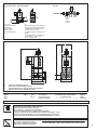
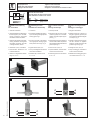
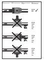
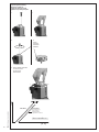
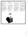
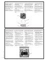
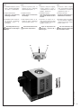
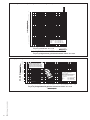
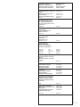
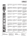
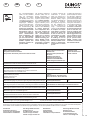
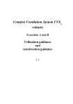
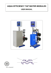
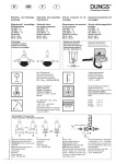
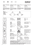
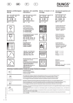
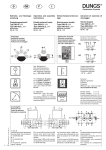
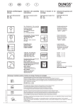
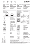
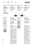
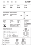
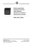
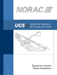
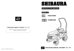
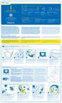
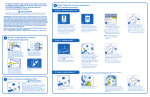
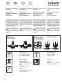
��
�
�
�
Betriebsund Montage��
�
anleitung
Operation
� and assembly
�
instructions
Notice d’emploi et de
montage
Istruzioni d’uso e di montaggio
Magnetventil
einstufige Betriebsweise
���
��
Typ
LV-D
Solenoid valve
Single-stage operation
�
Model�LV-D
Électrovanne de sécurité
Service à une allure
Type LV-D
Valvole elettromagnetiche
monostadio
Tipo LV-D
Nennweiten Rp 2
���
��
��
��
Nominal diameters Rp 2
��
��
�
��
Diamètre nominal Rp 2
Diametri nominali Rp 2
Die Armatur LV-D eignet sich
zum Absperren und Freigeben
der Hauptgasmenge von nicht
brennbaren Medien, stromlos geschlossen. Geeignet für
verschmutzte Medien durch
robusten elektromagnetischen
Antrieb mit Faltenbalg.
The LV-D valve is suitable for
blocking or enabling the main
flow of non-inflammable media
(NC). Its sturdy bellows-type
electromagnetic actuator makes
it suitable for contaminated
media.
Le robinet LV-D est utilisé pour
bloquer et libérer le débit de
gaz principal de matériaux non
combustibles, fermé hors tension . Il est approprié pour les
matériaux souillés grâce à son
entraînement électromagnétique
robuste avec soufflet.
L‘armatura LV-D è adatta per
il blocco e la fuoriuscita della
quantità di gas principale di
sostanze non infiammabili,
normalmente chiusa. Adatta
per sostanze impure, mediante
azionamento elettromagnetico
resistente con soffietto.
LV-D darf nicht für brennbare Gase eingesetzt werden; es sind ausschließlich
nichtbrennbare, innerte Medien
zulässig!
The LV-D must not be used
for inflammable gases; only
non-inflammable inert media are
allowed!
Le LV-D ne doit pas être
utilisé pour les gaz inflammables ; seuls les matériaux
inertes non combustibles not
autorisés !
LV-D non può essere impiegata per gas infiammabili;
sono consentite esclusivamente
sostanze non infiammabili e
inerti.
���
�
��
��
���
Einbaulage
��
��
�
��
���
Mounting position
Position de montage
Posizione di montaggio
Elektrischer Anschluß
Electrical connection
Raccordement électrique
Allacciamento elettrico
IEC 730-1 (VDE 0631 T1)
�
Erdung nach örtlichen Vorschriften
Grounding as per local regulations
Mise à terre selon les normes locales
Messa a terra secondo prescrizioni locali
�
�
�
�
[mbar]
Klasse A, Gruppe 2
Class A, Group 2
Classe A, Groupe 2
Classe A, Gruppo 2
in Anlehnung an / related to / conformément à / in conformità a
EN 161
M/CD • Edition 02.10 • Nr. 252 622
Un ~(AC) 230 V –15 % +10 %
1 … 12
[V]
oder / or / ou / o
~(AC) 110 V
=(DC) 24 V- 28V
Einschaltdauer/ Switch-on duration/
Durée de mise sous tension/ Ciclo di
funzionamento 100 %
°C
+60
0
-15
IEC 529
�
�
�
DC
Max. Betriebsdruck
Max. operating pressure
Pression de service maximum
Max. pressione di esercizio
pmax. = 500 mbar (50 kPa)
�
�
AC
Umgebungstemperatur
Ambient temperature
Température ambiante
Temperatura ambiente
-15 °C … +60 °C
Schutzart
Degree of protection
Protection
Protezione
IP 65 nach / acc. / selon / a norma
IEC 529 (DIN EN 60 529)
3
Druckabgriffe / Pressure taps
Prises de pression / Prese di pressione
1 (5) 2 4
Sieb
Sieve
Tamis
Reticella
LV-D 520
2
�
�
3 Sieb 2 5 1 4
�
�
Sieve
Tamis
Reticella
�
1, 2, 4, 3
Verschlußschraube
Screw plug
Bouchon fileté
Tappo a vite
G 1/8 DIN ISO 228
1
5
Anschlußmöglichkeit für Endkontakt
Capability of connecting to final contact
Possibilité de raccordement pour
contact de fin de course
Possibilità di attacco per finecorsa:
K01/1
Verschlußschraube / Sealing plug
Bouchon fileté / Tappo a vite
G 1/8 DIN ISO 228
�
�
�
Einbaumaße / Dimensions / Côte d‘encombrement / Dimensioni di ingombro [mm]
�
���
�
Platzbedarf für Magnetwechsel
Space required for changing solenoid
Encombrement pour le changement de l’électroaimant
Spazio necessario per sostituzione bobina
Typ
Model
Type
Tipo
Rp
Pmax.
[VA]
Imax.
~(AC)
230 V
Öffnungszeit
Opening time
Durée d’ouverture
Tempo di apertura
LV-D 520
Rp 2
50
0,22 A
< 1 sec
ISO 7005-2
19
[Nm]
Einbaumaße / Dimensions / Côte
d’encombrement / Dimensioni di
ingombro [mm]
e
b
a
c
d
f
g
238
165
114
370
126
39
Gewicht
Weight
Poids
Peso [kg]
6,9
47
Verschluß- und Verbindungsschrauben sachgemäß anziehen.
Werkstoffpaarung Druckguß – Stahl beachten!
Tighten plug and union screws properly.
Ensure die-cast – steel material combination!
Serrer convenablement les vis de fermeture et de fixation.
Respecter l’appariement des matériaux de moulage sous pression – acier!
Stringere in modo appropriato sia le viti di collegamento che i tappi a vite.
Prestare attenzione all’abbinamento dei materiali pressofusione – acciaio!
18
Max. Drehmomente / Systemzubehör
Max. torques / System accessories
Max. couple / Accessoires du système
Coppie max. / Accessori di sistema
M3
M4
M5
0,5 Nm 2,5 Nm 5 Nm
M6
M8
G1/8
G1/4
7 Nm
15 Nm 2,5 Nm 7 Nm
G1/2
G3/4
10 Nm 15 Nm
M/CD • Edition 02.10 • Nr. 252 622
d
�
2 … 12
Geeignetes Werkzeug einsetzen!
Use proper tools!
Utiliser des outils adaptés!
Impiegare attrezzi idonei!
M max.
SV
Tmax.
M max.
Schrauben kreuzweise anziehen!
Tighten screws crosswise!
Serrer les vis en croisant!
Stringere le viti secondo uno schema a croce!
Gerät darf nicht als Hebel benutzt werden!
Do not use unit as lever!
Ne pas utiliser la vanne comme levier!
Non utilizzare la valvola a mo’ di leva!
Rp
Mmax.
Tmax.
2
1100
250
[Nm] t ≤ 10 s
[Nm] t ≤ 10 s
Gewindeflanschausführung
LV-D
Ein- und Ausbau
Threaded flange version
LV-D
Installation and disassembly
Version à brides taraudées
LV-D
Montage / Démontage
Esecuzione con flangia filettata
LV-D
Montaggio e smontaggio
1.Gewinde schneiden
1.Cut thread
1.Découper le filet
1.Eseguire la filettatura
2.Ausgangsflansch und Eingangsflansch (Option) auf die Rohrleitung montieren. Geeignete
Dichtmittel verwenden, Bild 1.
2.Fit outlet and inlet flanges (optional) on the tubing Use appropriate
sealing agent, Fig. 1.
2.Monter la bride de sortie et celle
d’entrée (option) sur la conduite.
Utiliser de la pâte à joints appropriée, fig. 1.
2.Montare la flangia di uscita e la
flangia di ingresso (optional) sul
tubo. Utilizzare sigillanti adeguati
a tal scopo, Fig. 1.
3.Ventil eingangsseitig in die Rohrleitung montieren. Geeignetes
Dichmittel verwenden. Lage der
O-Ringe beachten, Bild 2.
3.Fit valve inlet side in the tubing.
Use appropriate sealing agent.
Note position of O rings, Fig. 2.
3.Monter la vanne dans la conduite, du
côté de l’entrée. Utiliser des produits
de bourrage appropriés. Attention aux
joints toriques. Fig. 2.
3.Montare la valvola sul lato ingresso
del tubo. Utilizzare un sigillante
adeguato. Prestare attenzione alla
posizione degli O-ring, Fig. 2.
4.Schrauben A, D, B, C anziehen.
4.Tighten screws A, D, B, C.
4.Serrer les vis A, D, B, C.
4.Stringere le viti A, D, B, C.
5.Nach Einbau Dichtheits- und
Funktionskontrolle.
5.Carry out leakage and functional
check after installation.
5.Après l’installation, contrôler l’étanchéité et le fonctionnement.
5.Dopo il montaggio, controllare la
tenuta e il funzionamento.
6.Ausbau in umgekehrter Reihenfolge 4 ➞ 3 ➞ 2.
6.Disassembly in reverse order
4➞ 3 ➞ 2.
6.Démontage dans l’ordre inverse
4➞ 3 ➞ 2.
6.Effettuare lo smontaggio seguendo l’ordine inverso 4➞ 3 ➞ 2.
1
3
2
C
D
5
M/CD • Edition 02.10 • Nr. 252 622
4
3 … 12
A
B
C
D
A
B
Degree of protection
IP 65
Please note position of bobbin!
Protection
IP 65
Tenir compte de la positon de
la bobine.
Protezione
IP 65
Prestare attenzione alla
posizione della bobina.
IP 65
OK
✓
IP 65
nein
no
non
no
IP 65
nein
no
non
no
IP 65
nein
no
non
no
M/CD • Edition 02.10 • Nr. 252 622
Schutzart
IP 65
Magnetstellung beachten!
4 … 12
LV-D
Hauptmengeneinstellung
Setting the main flow
Réglage du débit principal
Regolazione portata principale
1
1
2
2
Lösen
Unscrew
Désserrer
Allentare
3 Keine Gewalt anwenden
Do not use force
Ne pas forcer
Non sforzare
–
+
∆p
°
∆V
M/CD • Edition 02.10 • Nr. 252 622
min./mini
5 … 12
max./maxi.
Werkseinstellung
Factory setting
Réglage d‘usine
Regolazione in fabricca
°
°
V
= 0,1 x V
min./mini.
max./maxi.
[m 3 /h]
Replacing adjustment plate
1. Anlage ausschalten.
2. Sicherungslack über der Senkkopfschraube A entfernen.
3. Senkkopfschraube A ausschrauben.
4. Zylinderkopfschraube B ausschrauben.
5. Einstellteller C abheben.
6. Einstellteller C austauschen.
7. Senk- und Zylinderkopfschraube
wieder eindrehen.
Senkkopfschraube nur so
festziehen, daß Einstellteller
noch gedreht werden kann.
8. Senkkopfschraube A mit
Sicherungslack überziehen.
9. Dichtheitsprüfung über
Druckabgriff Verschlußschraube 3:
SV... pmax. = 500 mbar
10. Funktionskontrolle durchführen.
11. Anlage einschalten.
1. 2. 3.
Switch installation off.
Remove locking varnish from
countersunk screw A.
Unscrew countersunk screw A.
4. Unscrew socket head screw B.
5. Lift off adjustment plate C.
6. Replace adjustment plate C.
7. Screw in countersunk and
socket head screws again.
Tighten countersunk screw so
that adjustment plate can only
just be turned.
8. Coat countersunk screw A with
locking varnish.
9. Leakage test via pressure tap
screw plug 3:
SV... pmax. = 500 mbar
10. Carry out functional test.
11. Switch installation on.
A
C
B
Remplacement du disque de
réglage
Sostituzione del disco di regolazione
1. Mettre l’installation hors tension.
2. Éliminer le vernis de blocage audessus de la vis à tête fraisée A.
3. Dévisser la vis à tête fraisée A.
4. Dévisser la vis à tête cylindrique B.
1. Disinserire l’impianto.
2. Rimuovere la lacca di sigillo
sopra la vite a testa svasata A.
3. Svitare la vite a testa svasata A.
4. Svitare la vite a testa cilindrica B.
5. Soulever le disque de réglage C.
6. Remplacer le disque de réglage C.
7. Revisser les vis à tête fraisée et
à tête cylindrique.
Serrer la vis à tête fraisée jusqu’à
un point où l’on peut encore faire
tourner le disque de réglage.
8. Enduire la vis à tête fraisée A
de vernis de blocage.
9. Contrôle d’étanchéité via la
prise de pression du bouchon fileté 3:
SV... pmax. = 500 mbar
10. Procéder à un contrôle de
fonctionnement.
11. Mettre l’installation sous tension.
5. Sollevare il disco di regolazione C.
6. Sostituire il disco di regolazione C.
7. Riavvitare la vite a testa cilindrica e stringere la vite a testa
svasata lasciando che il disco
di regolazione possa ancora
ruotare.
8. Sigillare con la lacca la vite a
testa svasata A.
9. Prova di tenuta attraverso
il tappo a vite della presa di
pressione 3:
SV... pmax. = 500 mbar
10. Effettuare la prova di funzionamento.
11. Reinserire l’impianto.
M/CD • Edition 02.10 • Nr. 252 622
Austausch Einstellteller
6 … 12
Sieb reinigen
Cleaning the sieve
Nettoyer le tamis
Pulire la reticella
1.Gaszufuhr unterbrechen:
Kugelhahn schließen!
2.Schrauben 1 - 4 herausdrehen,
auf O-Ring (A) achten.
3.Metallsieb (B) herausnehmen.
4.Metallsieb (B) reinigen.
5.Metallsieb wieder einführen; auf
Führung im Gehäuse achten.
6.O-Ring einsetzen.
7.Bodendeckel einsetzen.
8.Schrauben 1 - 4 ohne Gewalt
hineindrehen und anziehen.
1.Interrupt the gas supply: close
the ball valve!
2.Unscrew screws 1 - 4, pay attention to the O-ring (A).
3.Remove the metal sieve (B).
4.Clean the metal sieve (B).
5.Insert the metal sieve again; pay
attention to the guidance in the
housing.
6.Insert the O-ring.
7.Insert the bottom cover.
8.Screw in screws 1 - 4 without
applying any force and tighten
them.
1.Couper l‘arrivée du gaz : fermer le
robinet à tournant sphérique !
2.Desserrer les vis 1 - 4, faire attention au joint torique (A).
3.Enlever le tamis métallique (B).
4.Nettoyer le tamis métallique (B).
5.Insérer le tamis métallique ; faire
attention au guidage dans le boîtier.
6.Insérer le joint torique.
7.Insérer le couvercle de fond.
8.Poser le vis 1 - 4 sans force et les
serrer.
1.Interrompere l‘alimentazione
di gas: chiudere il rubinetto
a sfere!
2.Svitare le viti 1 - 4 facendo
attenzione all‘anello torico (A).
3.Togliere la reticella metallica (B).
4.Pulire la reticella metallica (B).
5.Introdurre di nuovo la reticella
metallica, facendo attenzione
alla guida nel corpo.
6.Applicare l‘anello torico.
7.Applicare il coperchio di fondo.
8.Avvitare e stringere senza forza
le viti 1 - 4.
B
M/CD • Edition 02.10 • Nr. 252 622
A
7 … 12
3
1
4
2
Bypassbohrung anbringen
Producing a bypass bore
Faire un alésage bipasse
Eseguire un foro per bypass.
Die Armatur ist bereits für eine
Bypassbohrung vorbereitet. Maximaler Durchmesser der Bypassbohrung 15,0 mm.
1. Gaszufuhr unterbrechen:
Kugelhahn schließen!
2. Schrauben 1 - 4 herausdrehen, auf O-Ring (A) achten.
3. Schraube C ausschrauben.
4. Durch ausgeschraubte Bohrung C entstandene Bohrung
aufbohren; max. Bohrungsdurchmesser 15,0 mm.
5. Bohrung auf Durchgang prüfen.
6. Späne entfernen - zur Sicherheit Sieb ebenfalls reinigen.
7. Metallsieb wieder einführen;
auf Führung im Gehäuse
achten.
8. O-Ring einsetzen.
9. Bodendeckel einsetzen.
10. Schrauben 1 - 4 ohne Gewalt
hineindrehen und anziehen.
The device is already prepared
for a bypass bore. The maximum
diameter of the bypass bore is
15.0 mm.
1. Interrupt the gas supply:
close the ball valve!
2. Unscrew screws 1 - 4, pay attention to the O-ring (A).
3. Unscrew screw C.
4. Open the bore created by the
unscrewed bore C by boring;
the maximum bore diameter is
15.0 mm.
5. Check the bore for free transit.
6. Remove chips - for safety reasons, clean also the sieve.
7. Insert the metal sieve again; pay
attention to the guidance in the
housing.
8. Insert the O-ring.
9. Insert the bottom cover.
10. Screw in screws 1 - 4 without
applying any force and tighten
them.
Le robinet est déjà préparé pour
un alésage bipasse. Le diamètre
maximal de l‘alésage bipasse est
15,0 mm.
1. Couper l‘arrivée du gaz :
fermer le robinet à tournant
sphérique !
2. Desserrer les vis 1 - 4, faire
attention au joint torique (A).
3. Desserrer la vis C.
4. Aléser le trou produit par l‘alésage
desserré ; le diamètre maximal de
l‘alésage est 15,0 mm.
5. Vérifier le passage de l‘alésage.
6. Enlever les copeaux - par sécurité,
nettoyer également le tamis.
7. Insérer le tamis métallique ; faire
attention au guidage dans le
boîtier.
8. Insérer le joint torique.
9. Insérer le couvercle de fond.
10. Poser le vis 1 - 4 sans force et
les serrer.
L‘armatura è già pronta per un foro
per bypass. Diametro massimo del
foro di bypass: 15,00 mm.
1. Interrompere l‘alimentazione di gas: chiudere il
rubinetto a sfere!
2. Svitare le viti 1-4 facendo attenzione all‘anello torico (A).
3. Svitare e togliere la vite C.
4. Allargare il foro formatosi
togliendo la vite C; diametro
massimo del foro: 15,00 mm.
5. Verificare il passaggio del foro.
6. Rimuovere i trucioli - per
sicurezza pulire anche la
reticella.
7. Reintrodurre la reticella metallica facendo attenzione alla
guida nel corpo.
8. Applicare l‘anello torico.
9. Appicare il coperchio di fondo.
10. Avvitare e stringere senza
forza le viti 1-4.
C
Magnetwechsel
LV-D
Solenoid replacement
LV-D
Remplacement de l’aimant
LV-D
Sostituzione bobina
LV-D
1.Einstellteller entfernen, wie auf
Seite 7 “Austausch Einstellteller”, Punkt 1 - 5, beschrieben.
1.Remove adjustment plate, as
described on page 7 “Replacing
adjustment plate” points 1 - 5.
1.Déposer le disque de réglage,
comme indiqué en page 7
« Remplacement du disque de
réglage », points 1 à 5.
1.Rimuovere il disco di regolazione, come descritto a pagina
7 “Sostituzione del disco di
regolazione”, punti 1 - 5.
2.Magnet auswechseln.
Magnet-Nr. und Spannung
unbedingt beachten!
2.Replace solenoid.
Always observe solenoid No.
and voltage!
2.Remplacer l’aimant.
Tenir impérativement compte
de la réf. de l’aimant et de la
tension!
2.Sostituire la bobina.
Rispettare tassativamente il n.
della bobina e la tensione!
3.Einstellteller wieder montieren,
wie auf Seite 7 “Austausch
Einstellteller”, Punkt 7 - 11,
beschrieben.
3.Refit adjustment plate, as described on page 7 “Replacing
adjustment plate” points 7 - 11.
3.Remonter le disque de réglage comme indiqué en page
7 «Remplacement du disque de
réglage», points 7 à 11.
3.Rimontare il disco di regolazione, come descritto a pagina 7
“Sostituzione del disco di regolazione”, punti 7 - 11.
Nach Magnetwechsel TypAufkleber auf dem Magnet
anbringen!
Attach model-sticker to solenoid after replacement!
Après le remplacement de
l’aimant, y apposer l’affichette de type!
Una volta sostituita la bobina, apporre l’adesivo del
tipo sulla bobina stessa!
C
B
M/CD • Edition 02.10 • Nr. 252 622
A
8 … 12
LV-D 520
Durchfluß-Diagramm / Flow Diagram / Diagramme de débit / Diagramma di portata
200
100
90
80
70
60
50
40
30
∆p [mbar]
20
10
9
8
7
6
5
4
3
2
1,0
0,9
0,8
0,7
0,6
0,5
0,4
Basis
Based on
Base
Base
0,3
+ 15° C, 1013 mbar, trocken
+ 15° C, 1013 mbar, dry
+ 15° C, 1013 mbar, sec
+ 15° C, 1013 mbar, secco
0,2
1
1
° [m3/h] Luft/Air/Aria dv = 1,00
Vn
2
4
6
8 10
20
40
60 80 100
200
400
600 800 1000
° [m3/h] Erdgas/Natural gas/Gaz Naturel/Gas metano dv = 0,65
Vn
2
4
6
8 10
20
40
60 80 100
200
400
600 800 1000
Strömungsgeschwindigkeit / Flow velocity / Vitesse d‘écoulement / Velocità Flusso
200
Empfohlener Arbeitsbereich
Recommended working range
Zone de travail recommandée
Campo di lavoro raccomandato
150
125
100
80
DN, DIN 2441
65
50
40
32
30
25
20
5
10
M/CD • Edition 02.10 • Nr. 252 622
s
m/
20
s
m/
s
m/
Strömungsgeschwindigkeiten in schweren
Gewinderohren nach DIN 2441
Flow velocities in heavy threaded
tubes as per DIN 2441
Vitesses d‘écoulement dans les tuyaux filetés
lourds en fonction de la norme DIN 2441
Velocità di flusso in tubi filettati pesanti
a norma DIN 2441
s
30 m/s
s
50
m/
70
s
m/
0
10
10
9
8
7
6
1
9 … 12
m/
2
4
6
8 10
20
40
60 80 100
Basis
Based on
Base
Base
200
400
+ 15 °C, 1013 mbar, trocken
+ 15 °C, 1013 mbar, dry
+ 15 °C, 1013 mbar, sec
+ 15 °C, 1013 mbar, secco
600 800 1000
2000
° [m3/h] Erdgas/Natural gas/Gaz Naturel/Gas metano dv = 0,65
Vn
4000
Ersatzteile / Zubehör
Spare parts / Accessories
Pièces de rechange / access.
Parti di ricambio / Accessori
Bestell-Nummer
Order No.
No. de commande
Codice articolo
Verschlußschraube, flach mit
O-Ring
Screw plug, flat with O ring
Bouchon fileté
Tappo a vite, testa piana con O-ring
G 1/8
5 Stück / Set
5 Pieces / Set
5 Pièces / Set
5 Pezzi / Set
230 432
Set Zündgasflansch G1/2
G1/2 ignition gas flange set
Kit de bride taraudée G 1/2
Set per flangia gas di accensione G 1/2
LV-D 520
219 007
Einsteckscheibe
Insert washer
Disque à emboîtement
Disco ad innesto
LV-D 520
231 563
Leitungsdose, Schwarz
Line socket, black
Prise, noire
Connettore, nero
GDMW, 3 pol. + E
210 319
Anschlußflansch
Connecting flange
Bride de raccordement
Flangia di collegamento
LV-D 520 LV-D 520
LV-D 520
LV-D 520
Rp 1
Rp 1 1/4
Rp 1 1/2
Rp 2
242 227
242 228
242 229
242 230
Meßstutzen mit Dichtring
Instrument gland with sealing ring
Goujon
Attacco misuratore con anello
di tenuta
G 1/8
230 397
Ersatzmagnet
Replacement solenoid
Aimant de rechange
Bobina di ricambio
auf Anfrage
on request
sur demande
su richesta
Leiterplatte
Replacement solenoid
Carte imprimée
Scheda circuito stampato
auf Anfrage
on request
sur demande
su richesta
LV-D
241 148
Dichtungen für Flansche
Measuring connections with
sealing ring
Prise de pression avec joint
guarnizioni per flange
2 Stück/Set
2 Pieces/Set
2 Pièces/Set
2 Pezzi/Set
LV-D 520
230 444
M/CD • Edition 02.10 • Nr. 252 622
Einstellteller für Hauptmenge
Adjustment plate for main flow
Réglage de débit principal
Disco di regolazione portata
principale
10 … 12
Safety
first
M/CD • Edition 02.10 • Nr. 252 622
O.K.
11 … 12
Arbeiten am Magnetventil
dürfen nur von Fachpersonal durchgeführt
werden.
Work on the solenoid
valve may only be carried out by specialist
personnel.
Seul du personnel spécialisé peut effectuer des
travaux à l’électrovanne.
Qualsiasi operazione
effettuata sulle valvole
deve essere eseguita da
personale competente.
Flanschflächen schützen.
Schrauben kreuzweise
anziehen. Auf mechanisch
spannungsfreien Einbau
achten.
Protect flange faces.
Tighten screws crosswise! Ensure freedom
from mechanical strain.
Protéger les surfaces des
brides. Serrer les vis en
croisant. Éviter les tensions mécaniques lors du
montage.
Proteggere le superfici
della flangia. Stringere le viti secondo uno
schema a croce. Evitare
tensioni meccaniche in
sede di montaggio.
Direkter Kontakt zwischen
Magentventil und dem
aushärtendem Mauerwerk, Betonwänden, Fußböden ist nicht zulässig.
Do not allow any direct
contact between the solenoid and hardened masonry, concrete walls or
floors.
Éviter tout contact direct
entre l’électrovanne et la
maçonnerie, les cloisons
en bétons et planchers en
cours de séchage.
Evitare ogni contatto
diretto fra la valvola e
opere murarie, pareti in
calcestruzzo e pavimenti
non ancora perfettamente assestati.
Grundsätzlich nach
Teileausbau/-umbau neue
Dichtungen verwenden.
Always use new seals
after dismounting / modifying parts.
Après un démontage ou
une modification, toujours
utiliser des joints neufs.
In linea di massima,
dopo lo smontaggio e
il rimontaggio di alcune
parti, utilizzare nuove
guarnizioni.
Rohrleitungsdichtheitsprüfung: Kugelhahn vor
den Armaturen / SV…
schließen.
Tubing leakage test:
Close ball valve in front
of fittings / SV...
Contrôle de l’étanchéité
de la conduite: Fermer le
robinet à boisseau sphérique avant les accessoires
de tuyaux / SV…
Per la prova di tenuta
delle tubature: chiudere il
rubinetto a sfera a monte
delle valvole/ SV…
Nach Abschluß von Arbeiten am Magnetventil:
Dichtheits- und Funktionskontrolle durchführen.
On completion of work
on the solenoid valve:
carry out leakage and
functional tests.
Une fois les travaux terminés à l’électrovanne:
Procéder à un contrôle
de fonctionnement.
Al termine dei lavori
effettuati su una valvola
elettromagnetica: eseguire un controllo sia
della tenuta che del
funzionamento.
Niemals Arbeiten durchführen, wenn Gasdruck
oder Spannung anliegt.
Offenes Feuer vermeiden.
Öffentliche Vorschriften
beachten.
Never carry out work if
gas pressure or power is
applied. No naked flames.
Observe public regulations.
Ne jamais effectuer de
travaux lorsque la pression ou la tension sont
présentes. Éviter toute
flamme. Respecter les
réglementations.
Non eseguire mai lavori
in presenza di gas in
pressione o di tensione
elettrica. Evitare i fuochi
aperti e osservare le
normative.
Bei Nichtbeachtung der
Hinweise sind Personenoder Sachfolgeschäden
denkbar.
Non-observance of these
instructions may result in
personal injury or property damage.
Le non-respect de ces
instructions peut entraîner des dommages corporels et matériels.
La non osservanza di
quanto sopra può ingenerare danni alle persone o alle cose.
Alle Einstellungen und
Einstellwerte nur in Übereinstimmung mit der Betriebsanleitung des Kessel-/Brennerherstellers
ausführen.
Any adjustment and application-specific adjustment
values must be made in
accordance with the appliance-/boiler manufacturers
instructions.
Effectuer tous les réglages et réaliser les valeurs
de réglage uniquement
selon le mode d'emploi du
fabricant de chaudières et
de brûleurs.
Realizzare tutte le impostazioni e i valori impostati solo in conformità alle
istruzioni per l'uso del
costruttore della caldaia/
del bruciatore.
Änderungen, die dem technischen Fortschritt dienen, vorbehalten / We reserve the right to make alterations in the course of technical improvement/
Sous réserve de modifications servant au progrès technologique / La società si riserva qualsiasi modifica tecnica e costruttiva
Hausadresse
Head Offices and Factory
Usine et Services Administratifs
Amministrazione e Stabilimento
Karl Dungs GmbH & Co. KG
Siemensstr. 6-10
D-73660 Urbach, Germany
Telefon+49 (0)7181-804-0
Telefax+49 (0)7181-804-166
Briefadresse
Postal address
Adresse postale
Indirizzare la corrispondenza a
Karl Dungs GmbH & Co. KG
Postfach 12 29
D-73602 Schorndorf
e-mail [email protected]
Internet www.dungs.com
��
�
��
���
��
���
��
��
��
���
�
��
��
�
�
Die Druckgeräterichtlinie
(PED) und die Richtlinie
über die Gesamtenergieeffizienz von Gebäuden (EPBD) fordern eine
regelmässige Überprüfung
von Heizungsanlagen zur
langfristigen
Sicherstellung von hohen Nutzungsgraden und somit geringster Umweltbelastung. Es
besteht die Notwendigkeit sicherheitsrelevante
Komponenten nach Erreichen ihrer Nutzungsdauer auszutauschen.
Diese Empfehlung gilt
nur für Heizungsanlagen und nicht für Thermprozessanwendungen.
DUNGS empfiehlt den
Austausch gemäss folgender Tabelle:
�
��
�
��
�
�
Sicherheitsrelevante Komponente
Safety relevant component
Composant relatif à la sécurité
Componenti rilevanti dal punto di vista della sicurezza
���
��
�
The Pressure Equipment
Directive (PED) and the
Energy Performance of
Buildings Directive (EPBD)
require a periodic inspection of heating appliances in order to ensure a high
degree of efficiency over a
long term and, consequently, the least environmental
pollution. It is necessary
to replace safety-relevant components after
they have reached the
end of their useful life.
This
recommendation
applies only to heating
appliances and not to
industrial heating processes. DUNGS recommends replacing such
components according
to the following table:
��
�
��
��
���
Ventilprüfsysteme / Valve proving systems
Systèmes de contrôle de vannes / Sistemi di controllo valvole
Druckwächter / Pressure switch / Manostat / Pressostati
Feuerungsmanager mit Flammenwächter
Automatic burner control with flame safeguard
Dispositif de gestion de chauffage avec contrôleur de flammes
Gestione bruciatore con controllo fiamma
UV-Flammenfühler
Flame detector (UV probes)
Capteur de flammes UV
Sensore fiamma UV
La directive concernant les
chauffe-bains à pression
(PED) et la directive sur la
performance énergétique des
bâtiments (EPBD) exigent
une vérification régulière des
installations de chauffage,
afin de garantir à long terme
des taux d‘utilisation élevés et par conséquent une
charge
environnementale
minimum. Il est nécessaire
de remplacer les composants relatifs à la sécurité
lorsqu‘ils ont atteint la fin
de leur vie utile. Cette recommandation ne s‘applique qu‘aux installations
de chauffage et non aux
applications de processus
thermique. DUNGS recommande le remplacement,
conformément au tableau
qui suit :
La direttiva per apparecchi a
pressione (PED) e la direttiva
per l‘efficienza dell‘energia
totale per edifici (EPBD), esigono il controllo regolare degli
impianti di riscaldamento per
la garanzia a lungo termine di
un alto grado di rendimento e
con ciò di basso inquinamento ambientale. Ciò rende
necessaria la sostituzione
di componenti rilevanti dal
punto di vista della sicurezza alla scadenza della
loro durata di utilizzazione.
Questo suggerimento vale
solo per impianti di riscaldamento e non per impieghi per processi termici.
DUNGS consiglia detta
sostituzione in conformità
alla sottostante tabella:
NUTZUNGSDAUER
DUNGS empfiehlt den Austausch nach:
USEFUL LIFE
DUNGS recommends replacement after:
VIE UTILE
DUNGS recommande le
remplacement au bout de :
DURATA DI UTILIZZAZIONE
DUNGS consiglia la sostituzione dopo:
Schaltspiele
Operating cycles
Cycles de manoeuvres
Cicli di comando
10 Jahre/years/ans/anni
250.000
10 Jahre/years/ans/anni
N/A
10 Jahre/years/ans/anni
250.000
10.000 h
Betriebsstunden / Operating hours
Heures de service / Ore di esercizio
Gasdruckregelgeräte / Gas pressure regulators
Dispositifs de réglage de pression du gaz / Regolatori della pressione del gas
15 Jahre/years/ans/anni
Gasventil ohne Ventilprüfsystem* / Gas valve without valve testing system*
Vanne de gaz sans système de contrôle de vanne* / Valvola del gas senza sistema di controllo valvola*
10 Jahre/years/ans/anni
250.000
10 Jahre/years/ans/anni
N/A
10 Jahre/years/ans/anni
N/A
10 Jahre/years/ans/anni
N/A
Gasventil mit Ventilprüfsystem / Gas valve with valve testing system
Vanne de gaz avec système de contrôle de vanne / Valvola del gas con sistema di controllo valvola
Min. Gasdruckwächter / Low gas pressure switch
Manostat de gaz min. / Pressostato gas min.
Sicherheitsabblaseventil / Pressure relief valve
Soupape d‘évacuation de sécurité / Valvola di scarico di sicurezza
Gas-Luft-Verbundsysteme / Gas-air ratio control system
Systèmes combinés gaz/air / Sistemi di miscelazione gas-aria
* Gasfamilien I, II, III / Gas families I, II, III
Familles de gaz I, II, III / per i gas delle famiglie I, II, III
N/A
nach erkanntem Fehler / after error detection
après détection du défaut / dopo il rilevamento di errori
N/A kann nicht verwendet werden / not applicable
ne peut pas être utilisé / non può essere usato
Änderungen, die dem technischen Fortschritt dienen, vorbehalten / We reserve the right to make modifications in the course of technical development.
Sous réserve de tout modification constituant un progrès technique / Ci riserviamo qualsiasi modifica tecnica e costruttiva
Hausadresse
Head Offices and Factory
Usine et Services Administratifs
Amministrazione e Stabilimento
Karl Dungs GmbH & Co. KG
Siemensstr. 6-10
D-73660 Urbach, Germany
Telefon+49 (0)7181-804-0
Telefax+49 (0)7181-804-166
Briefadresse
Postal address
Adresse postale
Indirizzare la corrispondenza a
Karl Dungs GmbH & Co. KG
Postfach 12 29
D-73602 Schorndorf
e-mail [email protected]
Internet www.dungs.com
M/CD • Edition 02.10 • Nr. 252 622
�
12 … 12