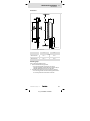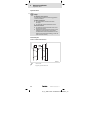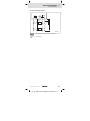
1
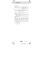
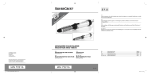
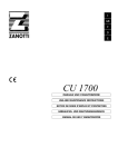
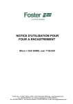
L−force Drives Ä.>ó1ä EDKRBM390R .>ó1 Montageanleitung Mounting Instructions Instructions de montage Instrucciones para el montaje Istruzioni per il montaggio ERB 50 ... 100 W ERBMxxxRxxxW Bremswiderstand Brake resistor Résistance de freinage Resistencia de frenado Resistenza di frenatura Lesen Sie zuerst diese Anleitung und die Dokumentation zum Grundgerät, bevor Sie mit den Arbeiten beginnen! Beachten Sie die enthaltenen Sicherheitshinweise. Please read these instructions and the documentation of the standard device before you start working! Observe the safety instructions given therein! Lire le présent fascicule et la documentation relative à l’appareil de base avant toute manipulation de l’équipement ! Respecter les consignes de sécurité fournies. Lea estas instrucciones y la documentación del equipo básico antes de empezar a trabajar. Observe las instrucciones de seguridad indicadas. Prima di iniziare qualsiasi intervento, leggere le presenti istruzioni e la documentazione relativa al dispositivo di base. Osservare le note di sicurezza. read_GG_DE−read_GG_IT ERBM84−001 Ausklappbild 0Abb. 0Tab. 0 Lieferumfang Pos. Beschreibung Bremswiderstand Montageanleitung Aufkleber mit Sicherheitshinweis Elemente am Bremswiderstand Pos. Beschreibung Typenschild Anschlussleitung Thermokontakt Anschlussleitung Bremswiderstand PE−Anschluss Gültigkeit Diese Anleitung ist gültig für ƒ Bremswiderstände ERBM100R100W ƒ Bremswiderstände ERBM180R050W ƒ Bremswiderstände ERBM390R100W Identifikation L 0 ERBMXXX011 Typenschlüssel ERBx xxxx xxxx Produktreihe Widerstand RB [W] z. B. 470R = 470 W 075D = 7,5 W Dauerleistung Pd [W] z. B. 4 120W = 120 W 01K2 = 1,2 kW EDKRBM390R DE/EN/FR/ES/IT 2.0 DUMMY_NUM_Reset−typbez Sicherheitshinweise 1 Definition der verwendeten Hinweise 1 Sicherheitshinweise Definition der verwendeten Hinweise Um auf Gefahren und wichtige Informationen hinzuweisen, werden in dieser Dokumentation folgende Piktogramme und Signalwörter verwendet: Sicherheitshinweise Aufbau der Sicherheitshinweise: Gefahr! (kennzeichnet die Art und die Schwere der Gefahr) Hinweistext (beschreibt die Gefahr und gibt Hinweise, wie sie vermieden werden kann) Piktogramm und Signalwort Bedeutung Gefahr! Gefahr von Personenschäden durch gefährliche elektrische Spannung Hinweis auf eine unmittelbar drohende Gefahr, die den Tod oder schwere Verletzungen zur Folge haben kann, wenn nicht die entsprechenden Maßnahmen getroffen werden. Gefahr! Gefahr von Personenschäden durch eine allgemeine Gefahrenquelle Hinweis auf eine unmittelbar drohende Gefahr, die den Tod oder schwere Verletzungen zur Folge haben kann, wenn nicht die entsprechenden Maßnahmen getroffen werden. Stop! Gefahr von Sachschäden Hinweis auf eine mögliche Gefahr, die Sachschäden zur Folge haben kann, wenn nicht die entsprechenden Maßnahmen getroffen werden. Anwendungshinweise Piktogramm und Signalwort Hinweis! Tipp! Bedeutung Wichtiger Hinweis für die störungsfreie Funktion Nützlicher Tipp für die einfache Handhabung Verweis auf andere Dokumentation EDKRBM390R DE/EN/FR/ES/IT 2.0 H1sic_DE−UR_Warn 5 1 Sicherheitshinweise Definition der verwendeten Hinweise Spezielle Sicherheitshinweise und Anwendungshinweise für UL und UR Piktogramm und Signalwort Bedeutung Warnings! Sicherheitshinweis oder Anwendungshinweis für den Betrieb eines UL−approbierten Geräts in UL−approbierten Anlagen. Möglicherweise wird das Antriebssystem nicht UL−gerecht betrieben, wenn nicht die entsprechenden Maßnahmen getroffen werden. Warnings! Sicherheitshinweis oder Anwendungshinweis für den Betrieb eines UR−approbierten Geräts in UL−approbierten Anlagen. Möglicherweise wird das Antriebssystem nicht UL−gerecht betrieben, wenn nicht die entsprechenden Maßnahmen getroffen werden. 6 EDKRBM390R DE/EN/FR/ES/IT 2.0 H1sic_DE−UR_Warn Sicherheitshinweise 1 Restgefahren Restgefahren Gefahr! Gefährliche elektrische Spannung Während des Betriebs des Grundgeräts und bis zu 3 Minuten nach dem Netzabschalten können an den Anschlüssen des Bremswiderstands gefährliche elektrische Spannungen anliegen. Mögliche Folgen: ƒ Tod oder schwere Verletzungen beim Berühren der Anschlussklemmen. Schutzmaßnahmen: ƒ Vor allen Arbeiten am Bremswiderstand das Grundgerät vom Netz trennen. ƒ Alle Leistungsklemmen auf Spannungsfreiheit prüfen. ƒ Den Montageort so wählen, dass die in den Technischen Daten genannten Einsatzbedingungen immer gewährleistet sind. Gefahr! Heiße Oberfläche Der Bremswiderstand kann sehr heiß werden. (Temperaturen siehe Technische Daten.) Mögliche Folgen: ƒ Schwere Verbrennungen beim Berühren des Bremswiderstands. ƒ Feuer oder Schwelbrand, wenn sich brennbare Materialien oder Stoffe in der Nähe des Bremswiderstands befinden oder dorthin gelangen können. Schutzmaßnahmen: ƒ Vor allen Arbeiten am Bremswiderstand dessen Oberflächentemperatur prüfen. ƒ Den Montageort so wählen, dass die in den Technischen Daten genannten Einsatzbedingungen immer gewährleistet sind. ƒ Den Montageort durch geeignete Brandschutz−Maßnahmen sichern. ƒ Aufkleber mit Sicherheitshinweis "Vorsicht, heiße Oberfläche" gut sichtbar nahe am Gerät anbringen. EDKRBM390R DE/EN/FR/ES/IT 2.0 H1sic_DE−UR_Warn 7 1 Sicherheitshinweise Restgefahren Warnings! Conditions of Acceptability − when used in the end−product equipment, the following are among the considerations to be made: ƒ The nominal loads of the resistors refer to conditions where the surrounding temperature does not exceed 40 °C. If the temperature exceeds 40 °C, contact LENZE for advice regarding de−rating of nominal power. ƒ The surface temperature must not exceed 355 °C at any point of the metal housing, as the insulation material inside the resistor is rated 600 °C maximum. The resistor housing reaches up to 335 °C at nominal load. ƒ These devices are enclosed type devices. Check that the surface, which the resistor is mounted on, can withstand the high temperature radiation and convection from the resistor surface. To protect personnel from contact with high temperature parts the resistors must be mounted minimum 6.5 feet (2 m) from the floor. ƒ A clearance of minimum 200 mm below and at each side and 500 mm above the resistors must be observed. ƒ The equipment must be properly connected to earth ground in the end−use equipment. ƒ The thermal cut−out, if provided, protects the resistor from destruction when over loaded at normal conditions. The suitability of the thermal cut−out at motor drive fault must be determined in the end−use application. ƒ The resistors are intended to be mounted with the longest side vertically or horizontally. Nominal load refers to the vertical position. Horizontal position requieres a load reduction of 20 %. If mounted vertically the connection box must face downwards. ƒ The resistors with protection class 4X / IP65 can be mounted in any allowed position whereas the 1X / IP21 types only meet the IP21 requirements when mounted vertically. ƒ Nominal load refers to mounting of a single resistor. If two or more resitors are mounted next to each other de−rating according to the above mentioned maximum surface temperatures are necessary. 8 EDKRBM390R DE/EN/FR/ES/IT 2.0 H1sic_DE−UR_Warn Technische Daten 2 2 Technische Daten Einsatzbedingungen Klimatische Bedingungen Klasse 3K3 nach EN 50178 Umgebungstemperatur −10 °C ... +55 °C über 45 °C Dauerleistung Pd um 2,5 %/°C reduzieren Aufstellhöhe 0 ... 4000 m üNN über 1000 m Dauerleistung Pd um 5 %/1000 m reduzieren Montageort l l l l Einbaulage ohne Betauung, mittlere relative Feuchte 85 % Im Schaltschrank Der Montageort muss den in den "Allgemeinen Daten" genannten Geräteeigenschaften entsprechen. Brennbare Materialien oder Stoffe dürfen sich nicht in der Nähe des Bremswiderstands befinden. Die vom Bremswiderstand erzeugte Wärme muss ungehindert abgeführt werden. Vertikal−hängend mit Anschlussleitungen unten. Einbaufreiräume oben > 200 mm unten > 100 mm seitlich > 30 mm Auslegung und Projektierung l l l l EDKRBM390R DE/EN/FR/ES/IT 2.0 Mittelwert der generatorischen Leistung < Dauerleistung Pd des Bremswiderstands. Generatorische Leistung während der Bremszeit < Wärmekapazität CB des Bremswiderstands. Bremszeit < 10 % der Zykluszeit (Bremszeit + Pausenzeit). Thermokontakt immer anschließen und so in die Anlagenüberwachung einbinden, dass bei Überhitzung des Bremswiderstands die Netzversorgung des Grundgeräts abgeschaltet wird. H1_Daten−BemDaten_Leg 9 2 Technische Daten Allgemeine Daten Konformität CE Niederspannungsrichtlinie Approbationen UR UL508, Industrial Control Equipment, Underwriter Laboratories (File−No. E208678) for USA and Canada Schutzart IP50 Rüttelfestigkeit Beschleunigungsfest bis 1 g Oberflächen−Temperatur im Normalbetrieb bis zu 300 °C im Fehlerfall mehr als 300 °C EN50178, IEC61800−5−1 und Germanischer Loyd, allgemeine Bedingungen Thermokontakt Ausführung Öffner, 200 °C Schaltleistung 250 V AC / 2A Bemessungsdaten Typ RB Pd CB Umax m [W] [W] [kWs] [VDC] [kg] ERBM100R100W 100 100 15 ERBM180R050W 180 50 7,5 ERBM390R100W 390 100 15 RB Widerstand Pd Dauerleistung CB Wärmekapazität Umax Max. Betriebsspannung m Masse 10 400 800 0,37 0,28 0,37 EDKRBM390R DE/EN/FR/ES/IT 2.0 H1_Daten−BemDaten_Leg Mechanische Installation 3 Abmessungen 3 Mechanische Installation Abmessungen ERBM82−003 Alle Maße in Millimeter a m [mm] ERBM100R100W 235 ±1 220 ±1 ERBM180R050W 175 ±1 160 ±1 ERBM390R100W 235 ±1 220 ±1 Montageschritte So montieren Sie den Bremswiderstand: 1. Wählen Sie einen geeigneten Montageort. – Der Montageort muss die in den Technischen Daten genannten Einsatzbedingungen immer gewährleisten; ggf. zusätzliche Maßnahmen ergreifen. 2. Verschrauben Sie den Bremswiderstand am Montageort. – Der Montageort und das Montagematerial muss die mechanische Verbindung dauerhaft gewährleisten. EDKRBM390R DE/EN/FR/ES/IT 2.0 H1_MechINS−mInstall 11 4 Elektrische Installation Wichtige Hinweise 4 Elektrische Installation Wichtige Hinweise Stop! Kein Schutz gegen Überlastung Eine Überlastung des Bremswiderstands während des Bremsbetriebs kann nicht grundsätzlich ausgeschlossen werden. Mögliche Folgen: ƒ Der Bremswiderstand überhitzt und wird zerstört. ƒ Der Antrieb wird nicht abgebremst sondern trudelt aus. Schutzmaßnahmen: ƒ Den Thermokontakt des Bremswiderstands immer anschließen. ƒ Den Thermokontakt so in die Anlagenüberwachung einbinden, dass bei Überhitzung des Bremswiderstands die Netzversorgung des Grundgerätes abgeschaltet wird (z. B. die Netzschütz−Ansteuerung abschalten). Anschlussplan Variante 1: Ohne Leitungsverlängerung RB f PE ERBMXXX012 Verdrillte Leitungen f 12 Länge der konfektionierten Leitungen 11 EDKRBM390R DE/EN/FR/ES/IT 2.0 H1_E_INST−Mech Installation Aufkleber Elektrische Installation 4 Anschlussplan Variante 2: Mit Leitungsverlängerung RB < 0.1 m PES <5m PE PES ERBMXXX014 HF−Schirmabschluss durch großflächige PE−Anbindung Verdrillte Leitungen EDKRBM390R DE/EN/FR/ES/IT 2.0 H1_E_INST−Mech Installation Aufkleber 13 4 Elektrische Installation Montageschritte Montageschritte ERBM82−004 So schließen Sie den Bremswiderstand an: 1. Grundgerät vom Netz trennen und alle Leistungsklemmen auf Spannungsfreiheit prüfen. 2. Bremswiderstand−Leitungen (RB1, RB2: transparente Litze) und Thermokontakt−Leitung (T1, T2: weiße Litze) verdrahten (siehe Dokumentation zum Grundgerät). – Wenn die Leitungslängen der konfektionierten Anschlussleitungen ausreichen, Anschlussleitungen verdrillen. (Anschlussplan Variante 1) – Wenn längere Leitungen benötigt werden (max. 5 m), die konfektionierten Leitungen auf mindestens 10 cm kürzen und auf externe Klemmstellen legen. Von dort geschirmte Leitungen verlegen. (Anschlussplan Variante 2) – Den Thermokontakt so in die Anlagenüberwachung einbinden, dass bei Überhitzung des Bremswiderstands die Netzversorgung abgeschaltet wird. 3. PE−Leiter mit Ringkabelschuh an PE−Gewindebolzen (M4) montieren. – PE−Anschluss nach EN 50178 ausführen. – Anzugsmoment beachten! 4. Aufkleber mit Sicherheitshinweis gut sichtbar nahe am Gerät anbringen! 14 EDKRBM390R DE/EN/FR/ES/IT 2.0 H1_E_INST−Mech Installation Aufkleber Wartung 5 Wartungsintervalle 5 Wartung Wartungsintervalle Der Bremswiderstand ist wartungsfrei. Trotzdem müssen Sie in regelmäßigen und unter Berücksichtigung der Umgebungsbedingungen ausreichend kurzen Intervallen eine Sichtprüfung durchführen. Kontrollieren Sie: ƒ Entspricht die Umgebung des Bremswiderstands noch den in den Technischen Daten genannten Einsatzbedingungen? ƒ Behindert kein Staub oder Schmutz die Wärmeabfuhr des Bremswiderstands? ƒ Sind die mechanischen und elektrischen Verbindungen in Ordnung? Wartungsarbeiten Bremswiderstand reinigen 1. Grundgerät vom Netz trennen und mindestens 3 Minuten warten. 2. Temperatur des Bremswiderstands prüfen. 3. Anschlüsse des Bremswiderstands auf Spannungsfreiheit prüfen. 4. Bremswiderstand ohne Reinigungsmittel säubern. EDKRBM390R DE/EN/FR/ES/IT 2.0 H1_wart−BrmWidReinigen 15 0Fig. 0Tab. 0 Scope of supply Pos. Description Brake resistor Mounting Instructions Sticker with safety warning Brake resistor elements Pos. Description Nameplate Connecting cable − thermal contact Connecting cable − brake resistor PE connection Validity These instructions are valid for ƒ Brake resistors ERBM100R100W ƒ Brake resistors ERBM180R050W ƒ Brake resistors ERBM390R100W Identification L 0 ERBMXXX011 Type code ERBx xxxx xxxx Product series Resistance RB [W] e.g. 470R = 470 W 075D = 7.5 W Permanent power Pd [W] e.g. 16 120W = 120 W 01k2 = 1.2 kW EDKRBM390R DE/EN/FR/ES/IT 2.0 DUMMY_NUM_Reset−typbez Safety instructions 1 Definition of notes used 1 Safety instructions Definition of notes used The following pictographs and signal words are used in this documentation to indicate dangers and important information: Safety instructions Structure of safety instructions: Danger! (characterises the type and severity of danger) Note (describes the danger and gives information about how to prevent dangerous situations) Pictograph and signal word Meaning Danger! Danger of personal injury through dangerous electrical voltage. Reference to an imminent danger that may result in death or serious personal injury if the corresponding measures are not taken. Danger! Danger of personal injury through a general source of danger. Reference to an imminent danger that may result in death or serious personal injury if the corresponding measures are not taken. Stop! Danger of property damage. Reference to a possible danger that may result in property damage if the corresponding measures are not taken. Application notes Pictograph and signal word Meaning Important note to ensure troublefree operation Note! Tip! Useful tip for simple handling Reference to another documentation EDKRBM390R DE/EN/FR/ES/IT 2.0 H1sic_EN−UR_Warn 17 1 Safety instructions Definition of notes used Special safety instructions and application notes for UL and UR Pictograph and signal word Meaning Warnings! Safety or application note for the operation of a UL−approved device in UL−approved systems. Possibly the drive system is not operated in compliance with UL if the corresponding measures are not taken. Warnings! Safety or application note for the operation of a UR−approved device in UL−approved systems. Possibly the drive system is not operated in compliance with UL if the corresponding measures are not taken. 18 EDKRBM390R DE/EN/FR/ES/IT 2.0 H1sic_EN−UR_Warn Safety instructions 1 Residual hazards Residual hazards Danger! Dangerous electrical voltage The terminals of the brake resistor may carry dangerous voltages during operation of the basic device and up to three minutes after mains disconnection. Possible consequences: ƒ Death or severe injuries when touching the terminals. Protective measures: ƒ Before working on the brake resistor disconnect the basic device from the mains. ƒ Check all power terminals for safe isolation from supply. ƒ Select the mounting location so that the operating conditions mentioned in the technical data are always ensured. Danger! Hot surface The brake resistor may get very hot. (Temperatures are listed in chapter "Technical data".) Possible consequences: ƒ Severe burns when touching the brake resistor. ƒ Fire or smouldering fire if flammable materials or substances are placed near the brake resistor or may get to it. Protective measures: ƒ Before working on the brake resistor check its surface temperature. ƒ Select the mounting location so that the operating conditions mentioned in the technical data are always ensured. ƒ Protect the mounting location by fire preventions. ƒ Attach the sticker with the "Caution, hot surface" safety warning in a prominent position near to the device. EDKRBM390R DE/EN/FR/ES/IT 2.0 H1sic_EN−UR_Warn 19 1 Safety instructions Residual hazards Warnings! Conditions of Acceptability − when used in the end−product equipment, the following are among the considerations to be made: ƒ The nominal loads of the resistors refer to conditions where the surrounding temperature does not exceed 40 °C. If the temperature exceeds 40 °C, contact LENZE for advice regarding de−rating of nominal power. ƒ The surface temperature must not exceed 355 °C at any point of the metal housing, as the insulation material inside the resistor is rated 600 °C maximum. The resistor housing reaches up to 335 °C at nominal load. ƒ These devices are enclosed type devices. Check that the surface, which the resistor is mounted on, can withstand the high temperature radiation and convection from the resistor surface. To protect personnel from contact with high temperature parts the resistors must be mounted minimum 6.5 feet (2 m) from the floor. ƒ A clearance of minimum 200 mm below and at each side and 500 mm above the resistors must be observed. ƒ The equipment must be properly connected to earth ground in the end−use equipment. ƒ The thermal cut−out, if provided, protects the resistor from destruction when over loaded at normal conditions. The suitability of the thermal cut−out at motor drive fault must be determined in the end−use application. ƒ The resistors are intended to be mounted with the longest side vertically or horizontally. Nominal load refers to the vertical position. Horizontal position requieres a load reduction of 20 %. If mounted vertically the connection box must face downwards. ƒ The resistors with protection class 4X / IP65 can be mounted in any allowed position whereas the 1X / IP21 types only meet the IP21 requirements when mounted vertically. ƒ Nominal load refers to mounting of a single resistor. If two or more resitors are mounted next to each other de−rating according to the above mentioned maximum surface temperatures are necessary. 20 EDKRBM390R DE/EN/FR/ES/IT 2.0 H1sic_EN−UR_Warn Technical data 2 2 Technical data Operating conditions Climatic conditions Class 3K3 to EN 50178 Ambient temperature −10 °C ... +55 °C Above 45 °C the permanent power Pd is to be reduced by 2.5 %/°C Installation height 0 ... 4000 m amsl Above 1000 m the permanent power Pd is to be reduced by 5 %/1000 m Mounting location l l l l Mounting position Without condensation, average relative humidity 85 % In the control cabinet The mounting location must comply with the device features mentioned in the chapter "General data". Flammable materials or substances must not be placed in the vicinity of the brake resistor. The heat generated by the brake resistor must be dissipated freely. Vertically suspended with connecting cables at the bottom. Free spaces at the top > 200 mm at the bottom > 100 mm to the sides > 30 mm Design and project planning l l l l EDKRBM390R DE/EN/FR/ES/IT 2.0 Mean value of regenerative power < permanent power Pd of brake resistor. Regenerative power during braking time < thermal capacity CB of brake resistor. Braking time < 10 % of cycle time (braking time + dead time). Always connect the thermal contact and integrate it in a way into the system monitoring that the mains supply will be switched off when the basic device is overheated. H1_Daten−BemDaten_Leg 21 2 Technical data General data Conformity CE Low−Voltage Directive Approvals UR UL508, Industrial Control Equipment, Underwriter Laboratories (File−No. E208678) for USA and Canada Degree of protection IP50 Vibration resistance Acceleration resistant up to 1 g Surface temperature In normal operation up to 300 °C In case of an error more than 300 °C EN50178, IEC61800−5−1 and Germanischer Lloyd, general conditions Thermal contact Design NC contact, 200 °C Switching capacity 250 V AC/2 A Rated data Type RB Pd CB Vmax m [W] [W] [kWs] [VDC] [kg] ERBM100R100W 100 100 15 ERBM180R050W 180 50 7.5 ERBM390R100W 390 100 15 RB Resistance Pd Permanent power CB Thermal capacity Vmax Max. operating voltage m Mass 22 400 800 0.37 0.28 0.37 EDKRBM390R DE/EN/FR/ES/IT 2.0 H1_Daten−BemDaten_Leg Mechanical installation 3 Dimensions 3 Mechanical installation Dimensions ERBM82−003 All dimensions in millimetres a m [mm] ERBM100R100W 235 ±1 220 ±1 ERBM180R050W 175 ±1 160 ±1 ERBM390R100W 235 ±1 220 ±1 Mounting steps How to mount the brake resistor: 1. Select a suitable mounting location. – The mounting location must always ensure the operating conditions mentioned in the technical data; if required, additional measures must be taken. 2. Screw down the brake resistor at the mounting location. – The mounting location and the mounting material must ensure the permanent mechanical connection. EDKRBM390R DE/EN/FR/ES/IT 2.0 H1_MechINS−mInstall 23 4 Electrical installation Important notes 4 Electrical installation Important notes Stop! No protection from overload An overload of the brake resistor during operation cannot be excluded. Possible consequences: ƒ The brake resistor overheats and will be damaged. ƒ The drive will not be decelerated but coasts. Protective measures: ƒ The thermal contact of the brake resistor must always be connected. ƒ Implement the thermal contact into the system monitoring so that the mains supply of the standard device will be switched off in case the brake resistor will be overheated (e.g. switch off mains contactor control). Connection plan Variant 1: without cable extension RB f PE ERBMXXX012 Twisted cables f 24 Length of prepared cables 23 EDKRBM390R DE/EN/FR/ES/IT 2.0 H1_E_INST−Mech Installation Aufkleber_en Electrical installation 4 Connection plan Variant 2: with cable extension RB < 0.1 m PES <5m PE PES ERBMXXX014 HF−shield termination by extensive PE connection Twisted cables EDKRBM390R DE/EN/FR/ES/IT 2.0 H1_E_INST−Mech Installation Aufkleber_en 25 4 Electrical installation Mounting steps Mounting steps ERBM82−004 How to connect the brake resistor: 1. Disconnect the basic device from the mains and check all power terminals for safe isolation from supply. 2. Connect brake resistor cables (RB1, RB2: transparent flexible) and thermal contact cable (T1, T2: white flexible) (see documentation for the basic device). – If the prepared connecting cables are long enough, twist them. (See connection plan, variant 1) – If longer cables are required (max. 5 m), shorten the prepared cables to at least 10 cm and connect them to external terminal connections. From there on, use shielded cables. (See connection diagram, variant 2) – When integrating the thermal contact into the system monitoring ensure that the mains supply will be switched off when the brake resistor is overheated. 3. Attach the PE conductor to the PE stud (M4) with the ring cable lug. – Implement PE connection according to EN 50178. – Observe tightening torque! 4. Place warning sticker close to the device in a clearly visible manner! 26 EDKRBM390R DE/EN/FR/ES/IT 2.0 H1_E_INST−Mech Installation Aufkleber_en Maintenance 5 Maintenance intervals 5 Maintenance Maintenance intervals The brake resistor is maintenance−free. Nevertheless, a visual inspection must be executed in short and regular intervals considering the ambient conditions. Ensure that: ƒ the environment of the brake resistor still corresponds to the operating conditions included in the technical data. ƒ no dust or dirt impedes the heat dissipation of the brake resistor. ƒ the mechanical and electrical connections are correct. Maintenance operations Cleaning the brake resistor 1. Disconnect the basic device from the mains and wait at least three minutes. 2. Check the temperature of the brake resistor. 3. Check the brake resistor for safe isolation from supply. 4. Clean brake resistor without using cleaning agents. EDKRBM390R DE/EN/FR/ES/IT 2.0 H1_wart−BrmWidReinigen 27 0Fig. 0Tab. 0 Equipement livré Pos. Description Résistance de freinage Instructions de montage Autocollant signalant le danger Eléments de la résistance de freinage Pos. Description Plaque signalétique Câble de raccordement pour le contact thermique Câble de raccordement pour la résistance de freinage Raccordement PE Validité Le présent document s’applique aux produits suivants : ƒ Résistances de freinage ERBM100R100W ƒ Résistances de freinage ERBM180R050W ƒ Résistances de freinage ERBM390R100W Identification L 0 ERBMXXX011 Codification des types ERBx xxxx xxxx Série d’appareils Résistance RB [W] Exem ple 470R = 470 W 075D = 7,5 W Puissance permanente Pd [W] Exem ple 28 120W = 120 W 01k2 = 1,2 kW EDKRBM390R DE/EN/FR/ES/IT 2.0 DUMMY_NUM_Reset−typbez Consignes de sécurité 1 Définition des conventions utilisées 1 Consignes de sécurité Définition des conventions utilisées Pour indiquer des risques et des informations importantes, la présente documentation utilise les mots et symboles suivants : Consignes de sécurité Présentation des consignes de sécurité Danger ! (Le pictogramme indique le type de risque.) Explication (L’explication décrit le risque et les moyens de l’éviter.) Pictogramme et mot associé Explication Danger ! Situation dangereuse pour les personnes en raison d’une tension électrique élevée Indication d’un danger imminent qui peut avoir pour conséquences des blessures mortelles ou très graves en cas de non−respect des consignes de sécurité correspondantes Danger ! Situation dangereuse pour les personnes en raison d’un danger d’ordre général Indication d’un danger imminent qui peut avoir pour conséquences des blessures mortelles ou très graves en cas de non−respect des consignes de sécurité correspondantes Stop ! Risques de dégâts matériels Indication d’un risque potentiel qui peut avoir pour conséquences des dégâts matériels en cas de non−respect des consignes de sécurité correspondantes Consignes d’utilisation Pictogramme et mot associé Remarque importante ! Conseil ! EDKRBM390R DE/EN/FR/ES/IT 2.0 Explication Remarque importante pour assurer un fonctionnement correct Conseil utile pour faciliter la mise en oeuvre Référence à une autre documentation H1sic_FR−UR_Warn 29 1 Consignes de sécurité Définition des conventions utilisées Consignes de sécurité et d’utilisation spécifiques selon UL et UR Pictogramme et mot associé Signification Warnings ! Consigne de sécurité ou d’utilisation pour le fonctionnement d’un appareil homologué UL dans des installations homologuées UL Le système d’entraînement risque de ne pas être utilisé selon les directives UL si des mesures correspondantes ne sont pas prévues. Warnings ! Consigne de sécurité ou d’utilisation pour le fonctionnement d’un appareil homologué UR dans des installations homologuées UL Le système d’entraînement risque de ne pas être utilisé selon les directives UL si des mesures correspondantes ne sont pas prévues. 30 EDKRBM390R DE/EN/FR/ES/IT 2.0 H1sic_FR−UR_Warn Consignes de sécurité 1 Dangers résiduels Dangers résiduels Danger ! Tension électrique dangereuse Les raccords de la résistance de freinage sont sous tension pendant le fonctionnement de l’appareil de base et jusqu’à 3 minutes après la coupure réseau. Risques encourus ƒ Mort ou blessures très graves en cas de contact accidentel avec les bornes de raccordement. Mesures de protection ƒ Couper l’appareil de base du réseau avant toute manipulation de la résistance de freinage ; ƒ Vérifier si les bornes de puissance sont hors tension ; ƒ Sélectionner l’emplacement de montage de façon à ce que les conditions d’utilisation (voir Spécifications techniques) soient garanties à tout instant. Danger ! Surface très chaude ! La résistance de freinage peut atteindre une température très élevée (se reporter aux spécifications techniques pour en savoir plus). Risques encourus ƒ Brûlures sévères en cas de contact avec la résistance de freinage ƒ Incendie ou feu couvant en présence de substances ou de matériaux inflammables à proximité de la résistance de freinage Mesures de protection ƒ Avant toute manipulation de la résistance de freinage, vérifier sa température de surface. ƒ Choisir un lieu de montage conforme aux conditions d’utilisation indiquées dans les spécifications techniques. ƒ Sécuriser le lieu de montage en recourant à des mesures anti−incendie adaptées. ƒ Appliquer un autocollant contenant la mention "Attention, surface très chaude". Ce dernier doit être bien visible et situé à proximité de l’équipement. EDKRBM390R DE/EN/FR/ES/IT 2.0 H1sic_FR−UR_Warn 31 1 Consignes de sécurité Dangers résiduels Warnings ! Conditions of Acceptability − when used in the end−product equipment, the following are among the considerations to be made: ƒ The nominal loads of the resistors refer to conditions where the surrounding temperature does not exceed 40 °C. If the temperature exceeds 40 °C, contact LENZE for advice regarding de−rating of nominal power. ƒ The surface temperature must not exceed 355 °C at any point of the metal housing, as the insulation material inside the resistor is rated 600 °C maximum. The resistor housing reaches up to 335 °C at nominal load. ƒ These devices are enclosed type devices. Check that the surface, which the resistor is mounted on, can withstand the high temperature radiation and convection from the resistor surface. To protect personnel from contact with high temperature parts the resistors must be mounted minimum 6.5 feet (2 m) from the floor. ƒ A clearance of minimum 200 mm below and at each side and 500 mm above the resistors must be observed. ƒ The equipment must be properly connected to earth ground in the end−use equipment. ƒ The thermal cut−out, if provided, protects the resistor from destruction when over loaded at normal conditions. The suitability of the thermal cut−out at motor drive fault must be determined in the end−use application. ƒ The resistors are intended to be mounted with the longest side vertically or horizontally. Nominal load refers to the vertical position. Horizontal position requieres a load reduction of 20 %. If mounted vertically the connection box must face downwards. ƒ The resistors with protection class 4X / IP65 can be mounted in any allowed position whereas the 1X / IP21 types only meet the IP21 requirements when mounted vertically. ƒ Nominal load refers to mounting of a single resistor. If two or more resitors are mounted next to each other de−rating according to the above mentioned maximum surface temperatures are necessary. 32 EDKRBM390R DE/EN/FR/ES/IT 2.0 H1sic_FR−UR_Warn Spécifications techniques 2 2 Spécifications techniques Conditions d’utilisation Conditions climatiques Classe 3K3 selon EN 50178 Température ambiante −10 °C ... +55 °C > 45 °C : réduire la puissance permanente Pd de 2,5 %/°C. Altitude d’implantation 0 ... 4000 m au−dessus du niveau de la mer > 1000 m : réduire la puissance permanente Pd de 5 %/1000 m. Emplacement de montage l l l l Position de montage Sans condensation, humidité relative moyenne 85 % Armoire électrique L’emplacement de montage doit correspondre aux caractéristiques indiquées au chapitre Caractéristiques générales. Des objets ou des matériaux combustibles ne doivent pas se trouver à proximité de la résistance de freinage. Assurer une ventilation suffisante pour évacuer la chaleur dissipée par la résistance de freinage. Position verticale avec câbles de raccordement vers le bas Espacements de montage En haut > 200 mm En bas > 100 mm Sur le côté > 30 mm Détermination pour l’application l l l l EDKRBM390R DE/EN/FR/ES/IT 2.0 Puissance génératrice moyenne < puissance permanente Pd de la résistance de freinage Puissance génératrice pendant le temps de freinage < capacité calorifique CB de la résistance de freinage Temps de freinage < 10 % du temps de cycle (temps de freinage + temps de repos) Raccorder impérativement le contact thermique et l’intégrer dans la surveillance de l’installation de façon à ce qu’en cas de surchauffe de la résistance de freinage, l’alimentation réseau de l’appareil de base soit coupée. H1_Daten−BemDaten_Leg 33 2 Spécifications techniques Caractéristiques générales Conformité CE Directive Basse Tension Homologations UR UL508, Industrial Control Equipment, Underwriter Laboratories (File−No. E208678) for USA and Canada Indice de protection IP50 Résistance aux chocs Résistance à l’accélératio n jusqu’à 1 g Température de surface Fonctionnement standard : jusqu’à 300 °C En cas de défaut : > 300 °C EN 50178, CEI 61800−5−1 et Germanischer Loyd, conditions générales Contact thermique Version Contact à ouverture, 200 °C Puissance de commutation 250 V CA / 2A Caractéristiques nominales Type RB Pd CB Umax m [W] [W] [kWs] [VDC] [kg] ERBM100R100W 100 100 15 ERBM180R050W 180 50 7,5 ERBM390R100W 390 100 15 RB Résistance Pd Puissance permanente CB Capacité calorifique Umax Tension de fonctionnement maxi m Poids 34 400 800 0,37 0,28 0,37 EDKRBM390R DE/EN/FR/ES/IT 2.0 H1_Daten−BemDaten_Leg Installation mécanique 3 Encombrements 3 Installation mécanique Encombrements ERBM82−003 Cotes en [mm] a m [mm] ERBM100R100W 235 ±1 220 ±1 ERBM180R050W 175 ±1 160 ±1 ERBM390R100W 235 ±1 220 ±1 Opérations de montage Ordre des opérations de montage de la résistance de freinage 1. Sélectionner l’emplacement de montage adéquat. – Sélectionner l’emplacement de montage de façon à ce que les conditions d’utilisation (voir Spécifications techniques) soient garanties à tout instant ; le cas échéant, prévoir des mesures supplémentaires. 2. Visser la résistance de freinage à l’emplacement de montage. – L’emplacement de montage et le matériel de montage doivent garantir une liaison mécanique permanente. EDKRBM390R DE/EN/FR/ES/IT 2.0 H1_MechINS−mInstall 35 4 Installation électrique Remarques importantes 4 Installation électrique Remarques importantes Stop ! Protection contre surcharge non garantie Pendant le fonctionnement en freinage, une surcharge de la résistance de freinage ne peut pas être exclue. Risques encourus ƒ Surchauffe et destruction de la résistance de freinage ƒ L’entraînement n’est pas freiné mais s’arrête sur son inertie. Mesures de protection ƒ Toujours connecter le contact thermique de la résistance de freinage. ƒ Intégrer le contact thermique dans le système de surveillance de l’installation de façon à ce qu’en cas de surchauffe de la résistance de freinage, l’alimentation de l’appareil de base soit coupée (exemple : coupure de la commande de l’interrupteur réseau). Schéma de câblage Variante 1 : sans rallongement des câbles RB f PE ERBMXXX012 Câbles torsadés f 36 Longueur des câbles précâblés 35 EDKRBM390R DE/EN/FR/ES/IT 2.0 H1_E_INST−Mech Installation Aufkleber Installation électrique 4 Schéma de câblage Variante 2 : avec rallongement des câbles RB < 0.1 m PES <5m PE PES ERBMXXX014 Connexion HF (collier de blindage) via connexion avec PE par surface importante Câbles torsadés EDKRBM390R DE/EN/FR/ES/IT 2.0 H1_E_INST−Mech Installation Aufkleber 37 4 Installation électrique Opérations de montage Opérations de montage ERBM82−004 Ordre des opérations de raccordement de la résistance de freinage 1. Couper l’appareil de base du réseau et s’assurer que toutes les bornes de puissance sont hors tension. 2. Brancher les câbles de la résistance de freinage (RB1, RB2 : tresse transparente) et le câble du contact thermique (T1, T2 : tresse blanche) (se reporter à la documentation de l’appareil de base). – Si la longueur des câbles de raccordement préconfectionnés est suffisante, torsader ces derniers (plan de raccordement, variante 1). – Pour des câbles plus longs (5 m max.), raccourcir les câbles préconfectionnés (10 cm au moins) et les relier à des borniers externes. De là, poser ensuite des câbles blindés (plan de raccordement, variante 2). – Intégrer le contact thermique dans le système de surveillance de l’installation, de manière à ce que l’alimentation réseau soit coupée en cas de surchauffe de la résistance de freinage. 3. Monter le conducteur PE sur le boulon fileté PE (M4) à l’aide d’une cosse à oeillet. – Procéder au raccordement PE suivant la norme EN 50178. – Respecter le couple de serrage ! 4. Appliquer un autocollant signalant le danger . Ce dernier doit être bien visible et situé à proximité de l’appareil ! 38 EDKRBM390R DE/EN/FR/ES/IT 2.0 H1_E_INST−Mech Installation Aufkleber Maintenance 5 Intervalles de maintenance 5 Maintenance Intervalles de maintenance La résistance ne nécessite aucun entretien. Cependant, il convient de procéder à des contrôles visuels réguliers. Selon les conditions ambiantes, prévoir des intervalles de contrôle suffisamment courts. Vérifier ƒ si les conditions ambiantes de la résistance de freinage correspondent toujours à celles indiquées au chapitre Spécifications techniques ; ƒ si des poussières ou dépôts éventuels risquent d’entraver la dissipation thermique de la résistance de freinage ; ƒ si les liaisons mécaniques et électriques sont correctes. Opérations de maintenance Nettoyage de la résistance de freinage 1. Couper l’appareil de base du réseau et attendre 3 minutes au minimum. 2. Vérifier la température de la résistance de freinage. 3. Vérifier si les raccords de la résistance de freinage sont hors tension. 4. Nettoyer la résistance de freinage (ne faire qu’un nettoyage à sec, sans agent détergent). EDKRBM390R DE/EN/FR/ES/IT 2.0 H1_wart−BrmWidReinigen 39 0Fig. 0Tab. 0 Contenido del suministro Pos. Descripción Resistencia de frenado Instrucciones para el montaje Pegatina con aviso de seguridad Elementos de la resistencia de frenado Pos. Descripción Placa de características Cable de conexión termocontacto Cable de conexión resistencia de frenado Conexión PE Validez Este manual es de aplicación para ƒ Resistencias de frenado ERBM100R100W ƒ Resistencias de frenado ERBM180R050W ƒ Resistencias de frenado ERBM390R100W Identificación L 0 ERBMXXX011 Código de tipo ERBx xxxx xxxx Serie de productos Resistencia RB [W] p.ej. 470R = 470 W 075D = 7,5 W Potencia constante Pd [W] p.ej. 40 120W = 120 W 01K2 = 1,2 kW EDKRBM390R DE/EN/FR/ES/IT 2.0 DUMMY_NUM_Reset−typbez Instrucciones de seguridad 1 Definición de las instrucciones utilizadas 1 Instruccionesde seguridad Definición de las instrucciones utilizadas Para indicar peligros e información importante, se utilizan en esta documentación los siguientes términos indicativos y símbolos: Instrucciones de seguridad Estructura de las instrucciones de seguridad: ¡Peligro! (indican el tipo y la gravedad del peligro) Texto indicativo (describe el peligro y da instrucciones para evitarlo) Pictograma y término indicativo Significado ¡Peligro! Riesgo de daños personales por voltaje eléctrico Indica un peligro inminente que puede causar la muerte o lesiones graves si no se toman medidas adecuadas. ¡Peligro! Riesgo de daños personales por una fuente de riesgo general Indica un peligro inminente que puede causar la muerte o lesiones graves si no se toman medidas adecuadas. ¡Alto! Peligro de daños materiales Indica un posible riesgo que puede ocasionar daños materiales si no se toman las medidas adecuadas. Instrucciones de uso Pictograma y término indicativo Significado Nota importante para el funcionamiento sin fallos ¡Aviso! ¡Sugerencia! EDKRBM390R DE/EN/FR/ES/IT 2.0 Sugerencia útil para facilitar la operación Referencia a otra documentación H1sic_ES−UR_Warn 41 1 Instrucciones de seguridad Definición de las instrucciones utilizadas Instrucciones de seguridad y de uso especiales para UL y UR Pictograma y término indicativo Significado Warnings ! Instrucción de seguridad o de uso para la utilización de un equipo con aprobación UL en instalaciones con aprobación UL. Posiblemente el sistema de accionamiento no funcionará según UL si no se toman las medidas adecuadas. Warnings ! Instrucción de seguridad o de uso para la utilización de un equipo con aprobación UR en instalaciones con aprobación UL. Posiblemente el sistema de accionamiento no funcionará según UL si no se toman las medidas adecuadas. 42 EDKRBM390R DE/EN/FR/ES/IT 2.0 H1sic_ES−UR_Warn Instrucciones de seguridad 1 Peligros residuales Peligros residuales ¡Peligro! Voltaje eléctrico peligroso Durante el funcionamiento del equipo básico y hasta 3 minutos tras la desconexión de la red las conexiones de la resistencia de frenado pueden mantener una tensión peligrosa. Posibles consecuencias: ƒ Muerte o lesiones graves al entrar en contacto con los bornes de conexión. Medidas de protección ƒ Separar el equipo básico de la red antes de realizar cualquier trabajo en el equipo básico. ƒ Comprobar que no haya ningún borne de potencia con tensión. ƒ Elegir el lugar de montaje de tal forma que siempre estén garantizadas las condiciones de uso indicadas en los datos técnicos. ¡Peligro! Superficie caliente La resistencia de frenado puede alcanzar temperaturas muy altas. (Ver datos técnicos) Posibles consecuencias: ƒ Quemaduras graves al entrar el contacto con la resistencia de frenado. ƒ Fuego o incendio sin llama si se encuentran materiales o sustancias inflamables cerca de la resistencia de frenado o si podrían llegar hasta ahí. Medidas de protección ƒ Antes de realizar cualquier trabajo en la resistencia de frenado comprobar la temperatura de la superficie. ƒ Elegir el lugar de montaje de tal forma que siempre estén garantizadas las condiciones de uso indicadas en los datos técnicos. ƒ Asegurar el lugar de montaje mediante medidas de protección contra incendios adecuadas. ƒ Colocar la pegatina con el aviso de seguridad "Cuidado, superficie caliente" cerca del equipo y de forma visible. EDKRBM390R DE/EN/FR/ES/IT 2.0 H1sic_ES−UR_Warn 43 1 Instrucciones de seguridad Peligros residuales Warnings ! Conditions of Acceptability − when used in the end−product equipment, the following are among the considerations to be made: ƒ The nominal loads of the resistors refer to conditions where the surrounding temperature does not exceed 40 °C. If the temperature exceeds 40 °C, contact LENZE for advice regarding de−rating of nominal power. ƒ The surface temperature must not exceed 355 °C at any point of the metal housing, as the insulation material inside the resistor is rated 600 °C maximum. The resistor housing reaches up to 335 °C at nominal load. ƒ These devices are enclosed type devices. Check that the surface, which the resistor is mounted on, can withstand the high temperature radiation and convection from the resistor surface. To protect personnel from contact with high temperature parts the resistors must be mounted minimum 6.5 feet (2 m) from the floor. ƒ A clearance of minimum 200 mm below and at each side and 500 mm above the resistors must be observed. ƒ The equipment must be properly connected to earth ground in the end−use equipment. ƒ The thermal cut−out, if provided, protects the resistor from destruction when over loaded at normal conditions. The suitability of the thermal cut−out at motor drive fault must be determined in the end−use application. ƒ The resistors are intended to be mounted with the longest side vertically or horizontally. Nominal load refers to the vertical position. Horizontal position requieres a load reduction of 20 %. If mounted vertically the connection box must face downwards. ƒ The resistors with protection class 4X / IP65 can be mounted in any allowed position whereas the 1X / IP21 types only meet the IP21 requirements when mounted vertically. ƒ Nominal load refers to mounting of a single resistor. If two or more resitors are mounted next to each other de−rating according to the above mentioned maximum surface temperatures are necessary. 44 EDKRBM390R DE/EN/FR/ES/IT 2.0 H1sic_ES−UR_Warn Datos técnicos 2 2 Datos técnicos Condiciones de uso Condiciones climatológicas Clase 3K3 según EN 50178 Temperatura ambiente −10 °C ... +55 °C por encima de 45 °C reducir potencia constante Pd en 2,5 %/°C Altura de montaje 0 ... 4.000 m s.n.m. por encima de 1.000 m reducir potencia constante Pd en 5 %/1.000 m Lugar de montaje l l l l Posición de montaje sin condensación, humedad relativa media 85 % En el armario eléctrico El lugar de montaje debe corresponder a las características del equipo indicadas en los "Datos generales". No deben encontrarse materiales o sustancias inflamables cerca de la resistencia de frenado. El calor generado por la resistencia de frenado se deberá poder eliminar sin obstáculos. Colgado en vertical con cables de conexión hacia abajo. Espacios libres para el montaje arriba > 200 mm abajo > 100 mm lateral > 30 mm Dimensionado y planificación l l l l EDKRBM390R DE/EN/FR/ES/IT 2.0 Media de la potencia modo generador < potencia permanente Pd de la resistencia de frenado. Potencia modo generador durante el tiempo de frenado < capacidad térmica CB de la resistencia de frenado. Tiempo de frenado < 10 % del tiempo cíclico (tiempo de frenado + tiempo de pausa). Siempre conectar el termocontacto e incluirlo en la monitorización de la instalación de forma que en caso de sobrecalentamiento de la resistencia de frenado se desconecte el suministro de red del equipo básico. H1_Daten−BemDaten_Leg 45 2 Datos técnicos Datos generales Conformidad CE Directiva de Bajo Voltaje Aprobaciones UR UL508, Industrial Control Equipment, Underwriter Laboratories (File−No. E208678) for USA and Canada Protección IP50 Resistencia a las sacudidas Resistente a la aceleración hasta 1 g Temperatura de la superficie en funcionamiento normal hasta 300 °C en caso de fallo más de 300 °C EN50178, IEC61800−5−1 y Germanischer Loyd, condiciones generales Termocontacto Ejecución NC, 200 °C Potencia de ruptura 250 V AC / 2A Datos nominales Tipo RB Pd CB Umáx m [W] [W] [kWs] [VDC] [kg] ERBM100R100W 100 100 15 ERBM180R050W 180 50 7,5 ERBM390R100W 390 100 15 RB Resistencia Pd Potencia constante CB Capacidad térmica Umáx Voltaje de red máx. m Masa 46 400 800 0,37 0,28 0,37 EDKRBM390R DE/EN/FR/ES/IT 2.0 H1_Daten−BemDaten_Leg Instalación mecánica 3 Dimensiones 3 Instalación mecánica Dimensiones ERBM82−003 Todas las medidas en milímetros a m [mm] ERBM100R100W 235 ±1 220 ±1 ERBM180R050W 175 ±1 160 ±1 ERBM390R100W 235 ±1 220 ±1 Pasos para el montaje Para montar la resistencia de frenado proceda de la siguiente manera: 1. Elegir el lugar de montaje adecuado. – El lugar de montaje se ha de elegir de tal forma que se garanticen en todo momento las condiciones de uso indicadas en los datos técnicos. Dado el caso tomar medidas adicionales. 2. Atornille la resistencia de frenado al lugar de montaje. – El lugar y el material de montaje debe garantizar una unión mecánica duradera. EDKRBM390R DE/EN/FR/ES/IT 2.0 H1_MechINS−mInstall 47 4 Instalación eléctrica Indicaciones importantes 4 Instalación eléctrica Indicaciones importantes ¡Alto! Sin protección contra sobrecarga Por regla general no se puede excluir una sobrecarga de la resistencia de frenado durante el funcionamiento de frenado. Posibles consecuencias: ƒ La resistencia de frenado se sobrecalienta y se destruye. ƒ El accionamiento no es frenado sino que produce tirabuzones. Medidas de protección: ƒ Conectar siempre el termocontacto a la resistencia de frenado. ƒ Integrar el termocontacto en la supervisión de equipos de modo que en caso de un sobrecalentamiento de la resistencia de frenado, se desconecte la fuente de alimentación del aparato básico (p. ej. desconexión del mando del contactor de red). Esquema de conexiones Variante 1: sin prolongación de cables RB f PE ERBMXXX012 Cables trenzados f 48 Longitud de los cables confeccionados 47 EDKRBM390R DE/EN/FR/ES/IT 2.0 H1_E_INST−Mech Installation Aufkleber Instalación eléctrica 4 Esquema de conexiones Variante 2: con prolongación de cables RB < 0.1 m PES <5m PE PES ERBMXXX014 Terminación de malla AF con conexión a PE de gran superficie Cables trenzados EDKRBM390R DE/EN/FR/ES/IT 2.0 H1_E_INST−Mech Installation Aufkleber 49 4 Instalación eléctrica Pasos para el montaje Pasos para el montaje ERBM82−004 Para conectar la resistencia de frenado proceda de la siguiente manera: 1. Desconectar equipo básico de la red y comprobar que no haya bornes de potencia bajo tensión que estén vivos. 2. Conectar cables de la resistencia de frenado (RB1, RB2: hilo transparente) y cable del termocontacto (T1, T2: hilo blanco) (ver documentación del equipo básico). – Si las longitudes de cable de los cables de conexión confeccionados son suficientes, trenzar cables de conexión (esquema de conexiones variante 1) – Si se necesitan cables más largos (máx. 5 m), recortar los cables confeccionados a por lo menos 10 cm y conectarlas a bornes externos. Desde ahí conectar cables apantallados. (Esquema de conexión variante 2) – Conectar el termocontacto a la monitorización de la instalación, de forma que en caso de sobrecalentamiento de la resistencia de frenado se desconecte la alimentación de red. 3. Montar conductor PE con terminal de anilla a espiga roscada PE (M4) . – Ejecutar la conexión de PE según la norma EN 50178. – ¡Respetar par de apriete! 4. ¡Colocar la pegatina con el aviso de seguridad cerca del equipo y de forma visible! 50 EDKRBM390R DE/EN/FR/ES/IT 2.0 H1_E_INST−Mech Installation Aufkleber Mantenimiento 5 Intervalos de mantenimiento 5 Mantenimiento Intervalos de mantenimiento La resistencia de frenado no precisa de mantenimiento. Sin embargo se deberá realizar una inspección visual regular a intervalos suficientemente cortos teniendo en cuenta las condiciones del entorno. Se ha de controlar lo siguiente: ƒ El entorno de la resistencia de frenado sigue cumpliendo con las condiciones de uso indicadas en los datos técnicos. ƒ Hay polvo o suciedad que impida la eliminación del calor de la resistencia de frenado. ƒ Las uniones mecánicas y eléctricas están en buen estado. Trabajos de mantenimiento Limpiar resistencia de frenado 1. Separar equipo básico de la red y esperar por lo menos 3 minutos. 2. Comprobar temperatura de la resistencia de frenado. 3. Comprobar que las conexiones de la resistencia de frenado no estén bajo tensión. 4. Limpiar resistencia de frenado sin utilizar detergentes. EDKRBM390R DE/EN/FR/ES/IT 2.0 H1_wart−BrmWidReinigen 51 0Fig. 0Tab. 0 Oggetto della fornitura Pos. Descrizione Resistenza di frenatura Istruzioni di montaggio Adesivo con avvertenza di sicurezza Elementi sulla resistenza di frenatura Pos. Descrizione Targhetta Conduttore del termocontatto Conduttore della resistenza di frenatura Collegamento PE Validità La presente documentazione è valida per ƒ Resistenze di frenatura ERBM100R100W ƒ Resistenze di frenatura ERBM180R050W ƒ Resistenze di frenatura ERBM390R100W Identificazione L 0 ERBMXXX011 Codice di identificazione ERBx xxxx xxxx Serie prodotto Resistenza RB [W] ad es. 470R = 470 W 075D = 7,5 W Potenza continuativa Pd [W] ad es. 52 120W = 120 W 01K2 = 1,2 kW EDKRBM390R DE/EN/FR/ES/IT 2.0 DUMMY_NUM_Reset−typbez Informazioni sulla sicurezza 1 Simbologia delle note e avvertenze utilizzate 1 Informazioni sulla sicurezza Simbologia delle note e avvertenze utilizzate Per segnalare pericoli ed informazioni importanti, nella presente documentazione sono riportati i seguenti simboli e parole di segnalazione: Note di sicurezza Struttura delle note di sicurezza: Pericolo! (indica il tipo e la gravità del pericolo) Testo della nota (descrive il pericolo e fornisce indicazioni su come può essere evitato) Simbolo e parola di segnalazione Significato Pericolo! Pericolo di danni alle persone dovuti a tensione elettrica Segnala una situazione di pericolo che può provocare morte o gravi lesioni se non vengono osservate le necessarie misure precauzionali. Pericolo! Pericolo di danni alle persone dovuti a una fonte generica di pericolo Segnala una situazione di pericolo che può provocare morte o gravi lesioni se non vengono osservate le necessarie misure precauzionali. Stop! Pericolo di danni materiali Segnala un possibile pericolo che può provocare danni materiali se non vengono osservate le necessarie misure precauzionali. Note di utilizzo Simbolo e parola di segnalazione Significato Avvertenza importante per assicurare un corretto funzionamento dell’apparecchiatura Nota: Suggerimen to: Utile suggerimento per un più semplice utilizzo Rimando ad altra documentazione EDKRBM390R DE/EN/FR/ES/IT 2.0 H1sic_IT−UR_Warn 53 1 Informazioni sulla sicurezza Simbologia delle note e avvertenze utilizzate Note di sicurezza e istruzioni d’uso speciali per UL e UR Simbolo e parola di segnalazione Significato Warnings ! Nota di sicurezza o istruzioni d’uso per il funzionamento di un dispositivo con omologazione UL in impianti omologati UL. Il funzionamento del sistema azionamento probabilmente non sarà conforme alla normativa UL, a meno che non vengano prese le necessarie misure a tal fine. Warnings ! Nota di sicurezza o istruzioni d’uso per il funzionamento di un dispositivo con omologazione UR in impianti omologati UL. Il funzionamento del sistema azionamento probabilmente non sarà conforme alla normativa UL, a meno che non vengano prese le necessarie misure a tal fine. 54 EDKRBM390R DE/EN/FR/ES/IT 2.0 H1sic_IT−UR_Warn Informazioni sulla sicurezza 1 Altri pericoli Altri pericoli Pericolo! Tensione elettrica pericolosa Durante il funzionamento del modulo asse e fino a 3 minuti dopo la disinserzione dalla rete possono permanere tensioni elettriche pericolose sui collegamenti della resistenza di frenatura. Possibili conseguenze: ƒ Morte o lesioni gravi in caso di contatto con i morsetti di collegamento. Misure di protezione: ƒ Prima di eseguire interventi sulla resistenza di frenatura, disinserire l’alimentazione del modulo asse. ƒ Verificare l’assenza di tensione su tutti i morsetti di potenza. ƒ Scegliere un luogo di montaggio idoneo, in modo che siano sempre garantite le condizioni di impiego specificate nei Dati tecnici. Pericolo! Superficie ustionante La resistenza di frenatura può raggiungere una temperatura molto elevata (per le temperature, vedere i Dati tecnici). Possibili conseguenze: ƒ Gravi ustioni in caso di contatto con la resistenza di frenatura. ƒ Incendio o combustione senza fiamma, qualora oggetti o materiali infiammabili siano presenti o possano finire nelle immediate vicinanze della resistenza di frenatura. Misure di protezione: ƒ Prima di eseguire interventi sulla resistenza di frenatura, controllare la temperatura della superficie. ƒ Scegliere il luogo di montaggio in modo che siano sempre garantite le condizioni di impiego specificate nei Dati tecnici. ƒ Proteggere il luogo di montaggio con misure antincendio appropriate. ƒ Applicare l’adesivo con l’avvertenza di sicurezza "Attenzione: superficie ustionante" accanto al dispositivo, in una posizione ben visibile. EDKRBM390R DE/EN/FR/ES/IT 2.0 H1sic_IT−UR_Warn 55 1 Informazioni sulla sicurezza Altri pericoli Warnings ! Conditions of Acceptability − when used in the end−product equipment, the following are among the considerations to be made: ƒ The nominal loads of the resistors refer to conditions where the surrounding temperature does not exceed 40 °C. If the temperature exceeds 40 °C, contact LENZE for advice regarding de−rating of nominal power. ƒ The surface temperature must not exceed 355 °C at any point of the metal housing, as the insulation material inside the resistor is rated 600 °C maximum. The resistor housing reaches up to 335 °C at nominal load. ƒ These devices are enclosed type devices. Check that the surface, which the resistor is mounted on, can withstand the high temperature radiation and convection from the resistor surface. To protect personnel from contact with high temperature parts the resistors must be mounted minimum 6.5 feet (2 m) from the floor. ƒ A clearance of minimum 200 mm below and at each side and 500 mm above the resistors must be observed. ƒ The equipment must be properly connected to earth ground in the end−use equipment. ƒ The thermal cut−out, if provided, protects the resistor from destruction when over loaded at normal conditions. The suitability of the thermal cut−out at motor drive fault must be determined in the end−use application. ƒ The resistors are intended to be mounted with the longest side vertically or horizontally. Nominal load refers to the vertical position. Horizontal position requieres a load reduction of 20 %. If mounted vertically the connection box must face downwards. ƒ The resistors with protection class 4X / IP65 can be mounted in any allowed position whereas the 1X / IP21 types only meet the IP21 requirements when mounted vertically. ƒ Nominal load refers to mounting of a single resistor. If two or more resitors are mounted next to each other de−rating according to the above mentioned maximum surface temperatures are necessary. 56 EDKRBM390R DE/EN/FR/ES/IT 2.0 H1sic_IT−UR_Warn Dati tecnici 2 2 Dati tecnici Condizioni di utilizzo Condizioni climatiche Classe 3K3 secondo EN 50178 Temperatura durante il funzionamento −10 °C ... +55 °C Per temperature maggiori di 45 °C, ridurre la potenza continuativa Pd del 2,5 %/°C Altitudine d’installazione 0 ... 4000 m s.l.m. Per altitudini superiori ai 1000 m, ridurre la potenza continuativa Pd del 5 %/1000 m Posizione di montaggio l l l l Posizione di montaggio Umidità relativa media 85 %, senza condensa Nell’armadio elettrico La posizione di montaggio deve essere conforme alle caratteristiche del dispositivo specificate nella sezione "Dati generali". Nelle vicinanze della resistenza di frenatura non devono trovarsi oggetti o materiali infiammabili. Il calore generato dalla resistenza di frenatura deve essere dissipato senza ostacoli. Verticale con cavi di collegamento sotto Quote di rispetto sopra > 200 mm sotto > 100 mm a lato > 30 mm Dimensionamento e progettazione l l l l EDKRBM390R DE/EN/FR/ES/IT 2.0 Valore medio della potenza in modo generatore < potenza continuativa Pd della resistenza di frenatura. Potenza in modo generatore durante il tempo di frenatura < capacità termica CB della resistenza di frenatura. Tempo di frenatura < 10 % del tempo di ciclo (tempo di frenatura + tempo di pausa). Collegare sempre il termocontatto integrandolo nella sorveglianza dell’impianto in modo che in caso di surriscaldamento della resistenza di frenatura l’alimentazione di rete del modulo asse venga disinserita. H1_Daten−BemDaten_Leg 57 2 Dati tecnici Dati generali Conformità CE Direttiva Bassa Tensione Omologazioni UR UL508, Industrial Control Equipment, Underwriter Laboratories (File−No. E208678) for USA and Canada Grado di protezione IP50 Resistenza alle vibrazioni Resistente ad accelerazioni fino a 1 g EN50178, IEC61800−5−1 e Germanischer Lloyd, condizioni generali Temperatura della superficie Nel funzionamento normale fino a 300 °C In caso di guasto oltre 300 °C Termocontatto Esecuzione Contatto chiuso a riposo (NC), 200 °C Potere di commutazion e 250 V AC / 2A Dati nominali Tipo RB Pd CB Umax m [W] [W] [kWs] [VCC] [kg] ERBM100R100W 100 100 15 ERBM180R050W 180 50 7,5 ERBM390R100W 390 100 15 RB Resistenza Pd Potenza continuativa CB Capacità termica Umax Tensione d’esercizio max. m Massa 58 400 800 0,37 0,28 0,37 EDKRBM390R DE/EN/FR/ES/IT 2.0 H1_Daten−BemDaten_Leg Installazione meccanica 3 Dimensioni 3 Installazione meccanica Dimensioni ERBM82−003 Tutte le quote sono in millimetri. a m [mm] ERBM100R100W 235 ±1 220 ±1 ERBM180R050W 175 ±1 160 ±1 ERBM390R100W 235 ±1 220 ±1 Procedura di montaggio Per montare la resistenza di frenatura, procedere come segue: 1. Selezionare un’ubicazione idonea per il montaggio. – Il luogo di montaggio prescelto deve sempre garantire le condizioni di impiego specificate nei Dati tecnici; in caso contrario, adottare misure aggiuntive. 2. Fissare con viti la resistenza di frenatura nella posizione di montaggio. – La posizione ed i componenti di montaggio devono garantire una connessione meccanica stabile. EDKRBM390R DE/EN/FR/ES/IT 2.0 H1_MechINS−mInstall 59 4 Installazione elettrica Note importanti 4 Installazione elettrica Note importanti Stop! Nessuna protezione contro sovraccarico Non è possibile escludere, in linea di massima, un sovraccarico della resistenza di frenatura durante il funzionamento in frenatura. Possibili conseguenze: ƒ Surriscaldamento e distruzione della resistenza di frenatura ƒ Mancata frenatura dell’azionamento, che continua a girare per inerzia. Misure di protezione: ƒ Collegare sempre il termocontatto della resistenza di frenatura. ƒ Integrare il termocontatto nel sistema di sorveglianza dell’impianto in modo che in caso di surriscaldamento della resistenza di frenatura venga scollegata l’alimentazione di rete del modulo asse (ad esempio, disattivare il comando del contattore di rete). Schema di collegamento Variante 1: senza prolungamento dei cavi RB f PE ERBMXXX012 Cavi intrecciati f 60 Lunghezza dei cavi confezionati 59 EDKRBM390R DE/EN/FR/ES/IT 2.0 H1_E_INST−Mech Installation Aufkleber Installazione elettrica 4 Schema di collegamento Variante 2: con prolungamento dei cavi RB < 0.1 m PES <5m PE PES ERBMXXX014 Schermatura HF con collegamento a PE ad ampia superficie Cavi intrecciati EDKRBM390R DE/EN/FR/ES/IT 2.0 H1_E_INST−Mech Installation Aufkleber 61 4 Installazione elettrica Procedura di montaggio Procedura di montaggio ERBM82−004 Per collegare la resistenza di frenatura, procedere come segue: 1. Disinserire l’alimentazione dell’inverter e verificare l’assenza di tensione su tutti i morsetti di potenza. 2. Collegare i cavi della resistenza di frenatura (RB1, RB2: cavetto trasparente) e il cavo del termocontatto (T1, T2: cavetto bianco) (vedere la documentazione dell’inverter). – Se la lunghezza dei cavi di collegamento confezionati è sufficiente, attorcigliare i cavi di collegamento (schema di collegamento, variante 1) – Qualora siano necessari cavi più lunghi (max. 5 m), accorciare i cavi confezionati lasciando almeno 10 cm e posarli su punti di crimpaggio esterni. Da qui collegare cavi schermati (schema di collegamento, variante 2) – Integrare il termocontatto nel sistema di sorveglianza dell’impianto in modo che in caso di surriscaldamento della resistenza di frenatura venga automaticamente disinserita l’alimentazione di rete. 3. Montare il conduttore PE con un terminale ad anello al perno filettato PE (M4) . – Eseguire il collegamento PE in conformità con la norma EN 50178. – Osservare la coppia di serraggio raccomandata. 4. Applicare l’adesivo con l’avvertenza di sicurezza in una posizione ben visibile accanto al dispositivo. 62 EDKRBM390R DE/EN/FR/ES/IT 2.0 H1_E_INST−Mech Installation Aufkleber Manutenzione 5 Intervalli di manutenzione 5 Manutenzione Intervalli di manutenzione La resistenza di frenatura non richiede manutenzione. Si raccomanda, tuttavia, di eseguire un controllo visivo ad intervalli regolari, con una frequenza ritenuta idonea in considerazione delle condizioni ambientali. Controllare quanto segue: ƒ Conformità dell’ambiente di installazione della resistenza di frenatura con le condizioni di impiego specificate nei Dati tecnici ƒ Assenza di polvere o sporco che ostruisca il dissipatore di calore della resistenza di frenatura ƒ Integrità dei collegamenti meccanici ed elettrici. Interventi di manutenzione Pulizia della resistenza di frenatura 1. Disinserire l’alimentazione del modulo asse ed attendere almeno 3 minuti. 2. Controllare la temperatura della resistenza di frenatura. 3. Controllare i collegamenti della resistenza di frenatura ed accertare che non vi sia tensione. 4. Pulire la resistenza di frenatura senza utilizzare detergenti. EDKRBM390R DE/EN/FR/ES/IT 2.0 H1_wart−BrmWidReinigen 63 © 06/2009 F Lenze Automation GmbH Grünstraße 36 D−40667 Meerbusch Germany Service Lenze Service GmbH Breslauer Straße 3 D−32699 Extertal Germany ( +49(0)21 32 /99 04−0 ( 008000/ 2446877 (24 h helpline) Ê +49(0)21 32 /7 21 90 Ê +49(0)5154/ 82−11 12 [email protected] [email protected] ü www.Lenze.com EDKRBM390R § .>ó1 § DE/EN/FR/ES/IT § 2.0 § TD29 10 backside 9 8 7 6 5 4 3 2 1