1
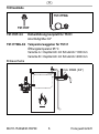
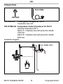
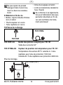
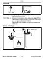
TS131
EB-TS131
Rev.D
Einbauanleitung • Installation instructions • Notice de montage
Istruzioni di montaggio • Instrukcja montażu
Anleitung zum späteren
Gebrauch aufbewahren!
Keep instructions for later use!
Conserver la notice pour usage
ultérieur!
Conservare le istruzioni per uso
successivo!
Zachowa instrukcj do pózniejszego wykorzystania!
Thermische Ablaufsicherung
Temperature Relief Valve
Thermique d'écoulement
Valvola di scarico termico
Termiczne zabezpieczenie
D
1. Sicherheitshinweise ............3
2. Funktionsbeschreibung .......3
3. Verwendung ........................ 3
4. Technische Daten ...............3
5. Lieferumfang .......................4
6. Varianten .............................4
7. Montage ..............................4
8. Instandhaltung..................... 5
9. Entsorgung ..........................5
10.Ersatzteile ........................... 6
17.Maintenance ..................... 13
18.Matériel en fin de vie ........ 14
19.Pièces de rechange .......... 14
I
1. Avvertenze di sicurezza .... 15
20.Descrizione del
funzionamento .................. 15
21.Uso ................................... 15
22.Dati tecnici ........................ 15
23.Fornitura ........................... 16
24.Varianti ............................. 16
25.Montaggio ......................... 16
26.Manutenzione ................... 17
27.Smaltimento ...................... 17
28.Ricambi ............................. 18
GB
1. Safety Guidelines ................7
2. Functional description .........7
3. Application ...........................7
4. Technical data .....................7
5. Scope of delivery .................7
6. Options ................................8
7. Assembly .............................8
8. Maintenance ........................9
9. Disposal ..............................9
10.Spare Parts .......................10
PL
1. Wskazówki
bezpieczenstwa ................. 19
29.Opis funkcji ....................... 19
30.Zastosowanie ................... 19
31.Dane techniczne ............... 19
32.Zakres dostawy ................ 20
33.Warianty ........................... 20
34.Montaz............................... 20
35.Utrzymywanie w dobrym
stanie ................................ 21
36.Usuwanie.......................... 22
37.CzÍúci zamienne ............... 22
F
1. Consignes de sécurité .......11
11.Description fonctionnelle ... 11
12.Mise en oeuvre ..................11
13.Caractéristiques ................ 12
14.Contenu de la livraison...... 12
15.Variantes ...........................12
16.Montage ............................ 12
MU1H-1543GE23 R0709
2
Honeywell GmbH
D
1. Sicherheitshinweise
1. Beachten Sie die Einbauanleitung.
2. Benutzen Sie das Gerät
• bestimmungsgemäß
• in einwandfreiem Zustand
• sicherheits- und gefahrenbewusst.
3. Beachten Sie, dass das Gerät
ausschließlich für den in dieser
Einbauanleitung genannten
Verwendungsbereich bestimmt
ist. Eine andere oder darüber
hinausgehende Benutzung gilt
als nicht bestimmungsgemäß.
4. Beachten Sie, dass alle
Montage-, Inbetriebnahme,
Wartungs- und Justagearbeiten
nur durch autorisierte Fachkräfte ausgeführt werden
dürfen.
5. Lassen Sie Störungen, welche
die Sicherheit beeinträchtigen
können, sofort beseitigen.
2. Funktionsbeschreibung
Die thermische Ablaufsicherung
wird von der Vorlauftemperatur
des Wärmeerzeugers gesteuert.
Sie besteht aus einem federbelasteten Ventil und einem Temperaturfühler, der auf ein Balgsystem
wirkt. Bei Erreichen einer VorlaufMU1H-1543GE23 R0709
temperatur im Heizkessel von
95 °C wird die Kraft im Balgsystem größer als die Federkraft
des Ventiles, und das Ventil öffnet.
Dadurch wird erwärmtes Trinkwasser abgeführt und durch kaltes
aus dem Netz ersetzt. Dieses
kann nun die überschüssige
Wärme aus dem Wassererwärmer
aufnehmen und eine Überhitzung
verhindern.
3. Verwendung
Wechselbrandkessel mit eingebautem Wassererwärmer oder
Kühlschlange in geschlossenen,
mit festen Brennstoffen beheizten
Heizungsanlagen nach EN 12828
4. Technische Daten
Leistungen der max. 100 kW
Heizungsanlagen
Öffnungstem- 95 °C
peratur
Leistung
2800 kg/h Wasser
bei einem Druckabfall von ∆p=1
bar (Eingangsdruck 5bar;
Ausgangsdruck
4bar) (1 Fühler)
AnschlussRp 3/4"
(DIN EN 10226)
größe
Betriebsdruck max. 5 bar
3
Honeywell GmbH
D
5. Lieferumfang
Die thermische Ablaufsicherung
besteht aus:
• Gehäuse mit Innengewinde
• Haube
• Ventilkegel mit Formdichtung
• Feder
• Externer Doppeltemperaturfühler mit Kapillarrohr
• Tauchhülse G 1/2" (ISO 228)
6. Varianten
TS131-3/4A
Öffnungstemperatur 95 °C
Kapillarrohr mit Schutzrohr
1300 mm bauteilgeprüft
TS131-3/4B
Öffnungstemperatur 95 °C
Kapillarrohr mit Schutzrohr
4000 mm
TS131-3/4Z
Sonderausführung auf Anfrage
7. Montage
7.1 Einbauhinweise
• Der Einbau des Ventiles und
des Fühlers ist sorgfältig vorzunehmen, damit Beschädigungen des Kapillarrohres
vermieden werden
• Die Mündung der Ausblaseleitung muss frei und beobachtbar
sein
MU1H-1543GE23 R0709
4
• Personen dürfen beim Abblasen
der Armatur nicht gefährdet
werden
• Es ist eine ausreichend bemessene Ablaufleitung vorzusehen
kvs-Werte ∆p = 1 bar
3 m3/h bei 2 unversehrten
Fühlersystemen
2,1 m3/h bei einem Fühlersystem
Achtung!
Der Einbau der thermischen
Ablaufsicherung ersetzt nicht
das Membran-Sicherheitsventil in der Kaltwasser-Zuführungsleitung zum
Wassererwärmer.
7.2 Montageanleitung
1. Thermische Ablaufsicherung
entsprechend dem
Einbauschema in die Warmwasserleitung einbauen
- Durchflussrichtung ist durch
Pfeil gekennzeichnet
2. Wärmefühler bis zum Anschlag
in das Tauchrohr einschieben
und mit der Rundkopfschraube
gegen Herausziehen sichern
Honeywell GmbH
D
7.3 Inbetriebnahme
Bei Inbetriebnahme der
Heizungsanlage muss der
Ersteller der Anlage die
einwandfreie Funktion der
thermischen Ablaufsicherung
überprüfen.
8. Instandhaltung
Wir empfehlen einen
Wartungsvertrag mit einem
Installationsunternehmen
abzuschließen
8.1 Inspektion und Wartung
• Entsprechend den Forderungen der DIN EN 12828
ist der Betreiber der Anlage
verpflichtet, die thermische
Ablaufsicherung mindestens
einmal jährlich durch einen
Fachkundigen auf ihre Funktionsbereitschaft prüfen zu
lassen.
• Durchführung durch ein
Installationsunternehmen
1. Prüfen ob Wasser aus dem
Gehäuse austritt
- tritt Wasser aus müssen die
Dichtungen (Kolbenführung
komplett) ersetzt oder das
Gerät gegebenfalls ausgetauscht werden
MU1H-1543GE23 R0709
2. Kontrollkappe betätigen und
prüfen ob zunächst Wasser
abläuft und das Ventil anschließend wieder schließt
- tritt kein Wasser aus oder
schließt das Ventil nicht muss
das Gerät gegebenfalls
ausgetauscht werden
8.2 Reinigung
• Durchführung durch ein
Installationsunternehmen
• Durchführung durch den
Betreiber
Zum Reinigen der Kunststoffteile keine lösungsmittel- und
alkoholhaltige Reinigungsmittel benutzen!
Es dürfen keine Reinigungsmittel in die Umwelt oder
Kanalisation gelangen!
9. Entsorgung
• Gehäuse, Haube und Tauchhülse aus Messing
• Temperaturfühler aus Kupfer
• Kapillarrohr aus Kupfer
• Ventilkegel aus Messing
• Dichtungen aus heißwasserbeständigem Elastomer
Die örtlichen Vorschriften zur
ordnungsgemäßen Abfallverwertung bzw. Beseitigung
beachten!
5
Honeywell GmbH
D
10.Ersatzteile
TS131TWG
TS131KF
TS131KF-3/4
Kolbenführung komplett für TS131
Anschlußgröße 3/4"
TS131TWG-3/4 Temperaturweggeber für TS131
Öffnungstemperatur 95°C
Variante A = Kapillarrohr mit Schutzrohr 1300 mm
Variante B = Kapillarrohr mit Schutzrohr 4000 mm
Einbauschema
min. DN20 (3/4“)
MU1H-1543GE23 R0709
6
Honeywell GmbH
GB
1. Safety Guidelines
1. Follow the installation instructions.
2. Use the appliance
• according to its intended use
• in good condition
• with due regard to safety and
risk of danger.
3. Note that the appliance is exclusively for use in the applications
detailed in these installation
instructions. Any other use will
not be considered to comply
with requirements and would
invalidate the warranty.
4. Please take note that any
assembly, commissioning,
servicing and adjustment work
may only be carried out by
authorized persons.
5. Immediately rectify any
malfunctions which may influence safety.
2. Functional description
The temperature relief valve is
actuated by the flow temperature
of the heat generator. It comprises
a spring-loaded valve and a
bellows operated temperature
sensor. When a boiler flow temperature of 95ºC is reached the force
exerted by the bellows system
MU1H-1543GE23 R0709
becomes greater than the force of
the spring and the valve opens.
Heated potable water then flows
out and this is replaced by cold
water from the supply network.
This absorbs excess heat from the
heat generator and prevents overheating.
3. Application
Multi-fuel boilers with integral
water heating or condensing coils
in closed solid-fuel fired heating
systems to EN 12828.
4. Technical data
Heating system max. 100 kW
capacity
Opening
95 °C
temperature
Flow capacity 2800 kg/h water at
the pressure drop
∆p=1 bar (Inlet
pressure 5bar;
Outlet pressure
4bar) (1 capillary
tube)
Connection
Rp 3/4"
(DIN EN 10226)
size
Operating pres-max. 5 bar
sure
5. Scope of delivery
The temperature relief valve
comprises:
• Housing with internal thread
7
Honeywell GmbH
GB
•
•
•
•
Bonnet
Valve piston with seal disc
Spring
Remote double temperature
sensor with capillary tube
• Immersion pocket G 1/2”
(ISO 228)
6. Options
TS131-3/4A
Opening temperature 95 °C
capillary tube with protection
sheath 1300 mm, with approved
construction
TS131-3/4B
Opening temperature 95 °C
capillary tube with protection
sheath 4000 mm
TS131-3/4Z
Special Versions available on
request
7. Assembly
7.1 Installations Guidelines
• The valve and the sensor must be
installed carefully to avoid any
damage to the capillary tube
• The opening on the blow-out
line must be clear and easy to
monitor
• Ensure no persons are in
danger when blowing off the
valve
MU1H-1543GE23 R0709
8
• A sufficiently dimensioned
discharge line must be provided
kvs-values ∆p = 1 bar
3 m3/h with 2 intact sensor
systems
2.1 m3/h with one sensor system
Attention!
Installation of the thermal
discharge safety valve does
not replace the diaphragm
relief value in the cold water
supply line to the water heater.
7.2 Assembly instructions
1. Install a thermal discharge
safety valve into the hot water
line according to the installation
diagram
- Flow direction is marked by
an arrow
2. Push the heat sensor into the
immersion pipe up to the stop
point and secure with a round
screw to stop it being pulled out
7.3 Commissioning
On commissioning the heating
system, the person preparing
the system must check that the
thermal discharge safety valve
is functioning perfectly.
Honeywell GmbH
GB
8. Maintenance
We recommend a planned
maintenance contract with an
installation company
8.1 Inspection and Maintenance
• According to the requirements of DIN EN 12828, the
system operator is obliged to
have the thermal discharge
safety valve checked by a
professional at least once a
year to ensure its functioning
capacity.
• To be carried out by an
installation company
1. Check whether water is escaping from the housing
- if water is escaping, the seals
(piston guide complete) must
be replaced or if necessary
the unit must be replaced
2. Operate the check valve and
first check if water is running off,
then close the valve again
- if no water is escaping or the
valve does not close, the unit
may have to be replaced
MU1H-1543GE23 R0709
8.2 Cleaning
• To be carried out by an
installation company
• To be carried out by the
operator
Do not use any cleaning
agents containing solvents or
alcohol to clean the plastic
parts!
Detergents must not be
allowed to enter the environment or the sewerage system!
9. Disposal
• Brass housing, bonnet and
immersion pocket
• Copper temperature sensor
• Copper capillary tube
• Brass valve piston
• Hot-water-resistant elastomer
seals
9
Honeywell GmbH
GB
10.Spare Parts
TS131TWG
TS131KF
TS131KF-3/4
Piston guide complete for TS131
Connection size 3/4"
TS131TWG-3/4 Temperature motion transducer for TS131
Opening temperature 95°C
Option A = Capillary tube with protection sheath
1300 mm
Option B = Capillary tube with protection sheath
4000 mm
Installation diagram
min. DN20 (3/4“)
MU1H-1543GE23 R0709
10
Honeywell GmbH
F
1. Consignes de sécurité
1. Suivre les indications de la
notice de montage.
2. En ce qui concerne l'utilisation
de l'appareil
• Utiliser cet appareil conformément aux données du constructeur
• Maintenir l'appareil en parfait
état
• Respectez les consignes de
sécurité
3. Il faut noter que cet équipement
ne peut être mis en oeuvre que
pour les conditions d'utilisation
mentionnées dans cette notice.
Toute autre utilisation, ou le non
respect des conditions
normales d'utilisation, serait
considérée comme non
conforme.
4. Observer que tous les travaux
de montage, de mise en
service, d'entretien et de
réglage ne pourront être effectués que par des spécialistes
autorisés.
5. Prendre des mesures immédiates en cas d'anomalies
mettant en cause la sécurité.
MU1H-1543GE23 R0709
2. Description fonctionnelle
Le sécurité thermique d'écoulement est commandée par la
température aller du radiateur.
Elle se compose d'une valve à
ressort et d'un thermocapteur qui
agit sur un système à soufflet.
Lorsque la température aller dans
la chaudière a atteint 95ºC, la
force dans le système à soufflet
est plus grande que celle du
ressort et la valve s'ouvre. L'eau
potable chaude peut alors
s'écouler et est remplacée par
l'eau froide du réseau. Celle-ci
peut alors absorber la chaleur
excédentaire de la chaudière et
empêcher une surchauffe.
3. Mise en oeuvre
Les chaudières mixtes avec
chauffe-eau intégré ou serpentin
dans un système de chauffage
fermé avec combustible solide
selon la norme EN 12828
11
Honeywell GmbH
F
4. Caractéristiques
6. Variantes
Puissances de max. 100 kW
l'installation de
chauffage
Température 95 °C
d'ouverture
Débit
2800 kg/h d’eau
pour une perte de
charge ∆p=1 bar
(Pression d’entrée
5bar; Pression de
sortie 4bar) (1 tube
capillaire)
Dimensions de Rp 3/4"
raccordement (DIN EN 10226)
Pression de max. 5 bar
service
TS131-3/4A
Température d'ouverture 95º C
Tube capillaire avec protection
1300 mm testé
TS131-3/4B
Température d'ouverture 95º C
Tube capillaire avec protection
4000 mm
TS131-3/4Z
Exécution spéciale sur demande
5. Contenu de la livraison
La sécurité thermique d'écoulement se compose de :
• Boîtier avec filetage intérieur
• Capot
• Cône de soupape avec joint
• Ressort
• Thermocapteur double externe
avec tube capillaire
• Douille d'immersion G 1/2"
(ISO 228)
MU1H-1543GE23 R0709
7. Montage
7.1Dispositions à prendre
• Le montage de la soupape et du
capteur doit être effectué
prudemment afin de ne pas
endommager le tube capillaire.
• L'embouchure de la conduite de
sortie doit être libre et observable
• Les personnes ne doivent pas
être mises en danger par le
crachement de la robinetterie
• Il convient de prévoir une
conduite d'écoulement suffisante
Valeurs kvs∆p = 1 bar
avec 2 systèmes intacts
3 m3/h
de capteurs
2.1 m3/h avec un système de
capteurs
12
Honeywell GmbH
F
8.1Inspection et Maintenance
• En accord avec la DIN EN
12828, l'exploitant de
l'installation s'oblige à faire
contrôler le fonctionnement
de la sécurité thermique
d'écoulement une fois par an
par du personnel spécialisé.
• Réalisation par une entreprise d'installation
1. Contrôlez si l'eau sort du boîtier
- Si de l'eau fuit, alors les joints
(guide des pistons complet)
doivent être remplacés ou
éventuellement l'appareil
échangé
2. Actionnez le clapet de contrôle
et contrôlez d'abord si l'eau
coule et si la soupape ensuite se
referme.
- Si l'eau ne coule pas ou si la
soupape ne se referme pas,
alors l'appareil doit être
échangé
8.2Nettoyage
• Réalisation par une entreprise d'installation
• Réalisation par l'exploitant
Attention !
Le montage de la sécurité thermique d'écoulement ne
remplace pas la soupape de
sécurité à membrane dans la
conduite d'alimentation d'eau
froide vers le chauffe-eau.
7.2Instructions de montage
1. Montez la sécurité thermique
d'écoulement, selon le plan de
montage, dans la conduite
d'eau chaude
- La direction du courant est
marquée par une flèche
2. Glissez les thermocapteur dans
la douille d'immersion jusqu'à la
butée et sécurisez avec une vis
à tête ronde
7.3Mise en service
Lors de la mise en service de
l'installation de chauffage, le
constructeur du système doit
contrôler le fonctionnement
parfait de la sécurité thermique
d'écoulement.
8. Maintenance
Nous recommandons de
conclure un contrat d'entretien
avec un installateur
MU1H-1543GE23 R0709
Ne pas utiliser de détergents
contenant des solvants ou de
l'alcool pour nettoyer les
parties en plastique!
13
Honeywell GmbH
F
• Cône de soupape en laiton
• Joints en élastomère résistant à
l'eau chaude
Se conformer à la réglementation pour l'élimination des équipements industriels en fin de
vie vers les filières de traitement autorisées!
Ne pas rejeter de produit
détergent dans l'environnement ou dans les canalisations!
9. Matériel en fin de vie
• Boîtier, capot et douille d'immersion en laiton
• Thermocapteur en cuivre
• Tube capillaire en cuivre
10.Pièces de rechange
TS131TWG
TS131KF
TS131KF-3/4
Guide des pistons complet pour TS 131
Taille des raccords 3/4"
TS131TWG-3/4
Capteur de position de température pour TS 131
Température d'ouverture 95 ºC variante A = tube
capillaire avec tube de protection 1300 mm
Variante B = Tube capillaire avec protection 4000 mm
Plan de montage
min. DN20 (3/4“)
MU1H-1543GE23 R0709
14
Honeywell GmbH
I
1. Avvertenze di sicurezza
1. Rispettare le istruzioni di
montaggio.
2. Utilizzare l'apparecchio
• secondo la destinazione d'uso
• solo se integro
• in modo sicuro e consapevoli
dei pericoli connessi
3. Si prega di considerare che
l'apparecchio è realizzato esclusivamente per il settore
d'impiego riportato nelle
presenti istruzioni d'uso. Un uso
differente o diverso da quello
previsto è da considerarsi
improprio.
4. Osservare che tutti i lavori di
montaggio, di messa in
funzione, di manutenzione e di
regolazione devono essere
eseguiti soltanto da tecnici
specializzati e autorizzati.
5. I guasti che potrebbero compromettere la sicurezza devono
essere risolti immediatamente.
2. Descrizione del funzionamento
La valvola di scarico termico viene
controllata dalla temperatura di
mandata del generatore di calore.
E' composta da una valvola caricata a molla e da un sensore di
temperatura che agisce sul
MU1H-1543GE23 R0709
sistema a soffietto. Raggiungendo
una temperatura di mandata di
95°C nella caldaia, la forza nel
sistema a soffietto supera la forza
della molla della valvola e la
valvola si apre. Così l'acqua potabile riscaldata viene condotta via e
sostituita da acqua fredda della
rete. Questa può quindi assorbire
il calore in eccesso prodotto dallo
scaldaacqua ed evitare un surriscaldamento.
3. Uso
Caldaia mista con generatore di
calore montato o serpentina di
raffreddamento in impianti di
riscaldamento a circuito chiuso
riscaldati con combustibili solidi
secondo la norma EN 12828.
4. Dati tecnici
Prestazioni
max. 100 kW
degli impianti di
riscaldamento
Temperatura di 95°C
apertura
Prestazione 2100 kg/h di acqua
con una pressione
di entrata minima di
1,0 bar (pressione in
ingresso 5 bar;
pressione in uscita 4
bar) (1 sensore)
15
Honeywell GmbH
I
Dimensioni
Rp 3/4"
(DIN EN 10226)
attacchi
Pressione di Max. 5 bar
esercizio
5. Fornitura
La valvola di scarico termico è
composta da:
• corpo con filettatura interna
• copertura
• cono della valvola con guarnizione sagomata
• molla
• doppio sensore di temperatura
esterno con tubo capillare
• Bussola a immersione G1/2"
(ISO 228)
6. Varianti
TS131-3/4A
Temperatura di apertura 95°C
Tubo capillare con guaina protettiva da 1300 mm, con struttura
controllata
TS131-3/4B
Temperatura di apertura 95° C
Tubo capillare con guaina protettiva da 4000 mm
TS131-3/4Z
Dotazione speciale su richiesta
7. Montaggio
7.1 Istruzioni di installazione
• Il montaggio della valvola e del
sensore deve essere eseguito
con attenzione per evitare danni
MU1H-1543GE23 R0709
al tubo capillare
• La bocca del tubo di scarico
deve essere libera e visibile
• Non mettere in pericolo le
persone durante lo scarico della
valvola
• Prevedere un tubo di scarico
della misura adeguata
Valorikvs ∆p = 1 bar
3 m3/h con due sistemi di
sensori integri
2,1 m3/h con un sistema di
sensori
Attenzione!
Il montaggio della valvola di
scarico termico non sostituisce
la valvola di sicurezza a
membrana nella condotta di
alimentazione dell'acqua
fredda verso il generatore
dell'acqua.
7.2 Istruzioni di montaggio
1. Montare la valvola di scarico
termico nella condotta
dell'acqua calda secondo lo
schema di montaggio
- La direzione di flusso è indicata dalla freccia
2. Inserire il termorivelatore nel
tubo ad immersione fino
all'arresto e assicurarlo con la
vite a testa tonda in modo che
non esca
16
Honeywell GmbH
I
7.3 Messa in funzione
Al momento della messa in
funzione dell'impianto di
riscaldamento, il realizzatore
dell'impianto deve controllare
che il funzionamento della
valvola di scarico termico sia
perfetto.
8. Manutenzione
Consigliamo di stipulare un
contratto di manutenzione con
un'azienda di installazione
8.1 Ispezione e manutenzione
• Secondo i requisiti della
norma DIN EN 12828, il
responsabile dell'impianto è
tenuto a far controllare la
funzionalità della valvola di
scarico termico almeno una
volta all'anno da personale
specializzato.
• attraverso un'azienda di
installazione
1. Controllare se fuoriesce acqua
dal corpo
- se fuoriesce acqua, sostituire
la guarnizione (completamente la guida del pistone) o
se necessario sostituire
l'apparecchio
2. Azionare il coperchio di
controllo e controllare prima se
MU1H-1543GE23 R0709
l'acqua scorre e poi se la valvola
si richiude
- se l'acqua non fuoriesce o se
la valvola non si chiude, sostituire l'apparecchio se necessario
8.2 Pulizia
• attraverso un'azienda di
installazione
• attraverso l'esercente
Per pulire le parti in plastica,
non utilizzare detergenti
contenenti solventi e alcol!
Nell'ambiente o nella canalizzazione è necessario che non
venga scaricato alcun detergente!
9. Smaltimento
• Corpo, copertura e boccola ad
immersione in ottone
• Sensore della temperatura in
rame
• Tubo capillare in rame
• Cono della valvola in ottone
• Guarnizioni in elastomero resistente all'acqua calda
Rispettare le norme locali relative al riciclaggio o allo smaltimento a regola d'arte di rifiuti!
17
Honeywell GmbH
I
10.Ricambi
TS131TWG
TS131KF
TS131KF-3/4
Guida del pistone completa per TS131
Misura del raccordo 3/4"
TS131TWG-3/4 Sensore di variazione della temperatura per TS131
Temperatura di apertura 95°C Variante A = tubo capillare con guaina protettiva 1300 mm
Variante B = tubo capillare con guaina protettiva da
4000 mm
Schema di montaggio
min. DN20 (3/4“)
MU1H-1543GE23 R0709
18
Honeywell GmbH
PL
1. Wskazówki bezpieczeństwa
1. Przestrzegać instrukcji
montażu.
2. Proszę użytkować przyrząd
- zgodnie z jego przeznaczeniem
- w nienagannym stanie
- ze świadomością bezpiec
zeństwa i zagrożeń
3. Proszę uwzględnić, że przyrząd
przeznaczony jest wyłącznie dla
zakresu zastosowania określo
nego w niniejszej instrukcji
montażu. Każde inne lub
wykraczające poza to użytko
wanie uznawane jest jako niez
godne z przeznaczeniem.
4. Proszę uwzględnić, że
wszystkie prace montażowe
mogą być wykonywane tylko
przez autoryzowany personel
fachowy.
5. Wszystkie te zakłócenia, które
mogą naruszyć bezpieczeństwo
należy natychmiast usunąć.
MU1H-1543GE23 R0709
2. Opis funkcji
Termiczne zabezpieczenie
odpływowe jest zaworem urucha
mianym temperaturą czynnika na
wylocie ze źródła ciepła. Składa
się ono z zaworu sprężynowego
oraz czujnika temperatury
działającego na układ miechowy.
Gdy temperatura w kotle grzew
czym osiągnie 95 °C siła w
układzie miechowym jest większa
niż nacisk sprężyny, co powoduje
otwarcie zaworu. W ten sposób
zostaje odprowadzona podgrzana
wodna pitna i zastąpiona poprzez
zimną z sieci. Przejmuje ona
nadmiar ciepła z podgrzewacza
wody i zapobiega tym samym
przegrzaniu.
3. Zastosowanie
Kotły ze zintegrowanym podgrze
waczem wody lub wężownicą
schładzającą stosowane w
zamkniętych instalacjach grzewc
zych na paliwa stałe wg normy EN
12828
19
Honeywell GmbH
PL
4. Dane techniczne
Moc
maks. 100 kW
instalacji
grzewczej
Tempera
95 °C
tura otwarcia
Przepływ
2800 kg/h wody przy
spadku ciśnienia ∆p=1
bar (Ciśnienie wejś
ciowe 5 bar; Ciśnienie
wyjściowe 4 bar) (1
rurka kapilarna).
Rozmiar
Rp 3/4"
przyłącza (DIN EN 10226)
Ciśnienie maks 5 bar
robocze
MU1H-1543GE23 R0709
20
5. Zakres dostawy
Zabezpieczenie termiczne składa
się:
- Korpus z gwintem
wewnętrznym
- Osłona
- Grzybek zaworu z profilowanym
uszczelnieniem
- Sprężyna
- Zewnętrzny podwójny czujnik
temperatury z rurką kapilarną
- Tulejka zanurzeniowa G 1/2"
(ISO 228)
6. Warianty
TS131-3/4A
Temperatura otwarcia 95 °C
Rurka kapilarna z rurką ochronną
1300 mm certyfikowana
TS131-3/4B
Temperatura otwarcia 95 °C
Rurka kapilarna z rurką ochronną
4000 mm
TS131-3/4Z
Wersje specjalne na zamówienie
Honeywell GmbH
PL
7. Montaż
7.1 Montaż
- Montaż zaworu oraz czujnika
należy przeprowadzić w
staranny sposób, tak by nie
uszkodzić rurki kapi larnej
- Wylot przewodu
wydmuchowego nie może być
zatkany i musi być widoczny
- Wydmuchiwanie armatury nie
może stanowić zagrożenia dla
osób
- Należy zastosować przewód
odprowadzający od odpowied
nich wymiarach
7.2 Instrukcja montażu
1. Termiczne zabezpieczenie
odpływowe należy zamontować
w przewodzie ciepłej wody
zgodnie ze schematem
montażowym
- Kierunek przepływu oznac
zono strzałką
2. Czujnik termiczny wsunąć do
oporu w rurkę zanurzeniową
zabezpieczyć przed wyciagnię
ciem śrubą
7.3 Rozpoczęcie eksploatacji
Przed oddaniem instalacji do
użytku wykwalifi kowany insta
lator powinien sprawdzić
popraw ność działania zabez
pieczenia termicznego.
kvs-wartości ∆p = 1 bar
3 m3/h
przy 2 sprawnych
systemach czujników
2.1 m3/h przy jednym
systemie czujników
8. Utrzymywanie w dobrym
stanie
Zalecamy zawarcie umowy
konserwacyjnej z odpowiednią
firmą instalacyjną¶
Uwaga!
Montaż zabezpieczenia
termicznego nie zastępuje
przeponowego zaworu
bezpiec zeństwa w układzie
doprowadzającym wodę
zimną do podgrzewacza wody.
MU1H-1543GE23 R0709
21
Honeywell GmbH
PL
8.1 Inspekcja i Konserwacja
- Zgodnie z wymogami normy
DIN EN 12828 użytkujący
instalację ma obowiązek
zlecić wykwalifikowanemu
instalatorowi przynajm niej
raz w roku kontrolę
poprawności działania
zabezpieczenia termicz
nego.
- Kontrolę powinna przepro
wadzić firma insta latorska
1. Należy sprawdzić, czy z
korpusu nie wycieka woda
- w przypadku wycieku wody
należy wymienić uszc
zelnienia (zespół tłoka komplet) lub w razie potrzeby
całe urządzenie
2. Uruchomić pokrywę kontrolną i
sprawdzić czy odpływa woda a
zawór następnie ponownie
zamyka
- jeżeli nie wypływa woda lub
zawór nie zamyka urządzenie
należy wymienić
MU1H-1543GE23 R0709
8.2 Czyszczenie
- Kontrole powinna przepro
wadzić firma instalatorska.
- Przeprowadzane przez
użytkującego
Do czyszczenia czÍúci
z tworzywa sztucznego nie
uřywaĘ úrodkŰw do czyszc
zenia, zawierajĽcych rozpusz
czalniki i alkohol!
Żadne środki czyszczące nie
powinny dostać się do środo
wiska naturalnego lub kanali
zacji!
9. Usuwanie
- Korpus, osłona i tulejka
zanurzeniowa z mosiądzu
- Czujnik temperatury z miedzi
- Rurka kapilarna z miedzi
- Grzybek zaworu z mosiądzu
- Uszczelnienia z odpornych na
działanie gorącej wody elasto
merów
Należy stosować się do miejs
cowych przepisów
dotyczących prawidłowego
wykorzystania odpadów wzgl.
ich usuwania!
22
Honeywell GmbH
PL
10.Części zamienne
TS131TWG
TS131KF
TS131KF-3/4
Zespół tłoka - komplet do TS131
Rozmiar przyłącza 3/4"
TS131TWG-3/4 Termostat TS131
Temperatura otwarcia 95 °Cwersja A = rurka kapilarna
z rurką ochronną 1300 mm
wersja B = rurka kapilarna z rurką ochronną 4000 mm
Schematem montażowym
min. DN20 (3/4“)
MU1H-1543GE23 R0709
23
Honeywell GmbH
Automation and Control Solutions
Manufactured for and on behalf of the
Honeywell GmbH
Environmental and Combustion Controls Division of HoHardhofweg
neywell Technologies Sàrl, Rolle, Z.A. La Pièce 16,
D-74821 Mosbach
Switzerland by its Authorised Representative Honeywell
GmbH
Phone: (49) 6261 810
Fax: (49) 6261 81309
MU0H-1543GE23 R0709
http://europe.hbc.honeywell.com Subject to change
© 2009 Honeywell GmbH
www.honeywell.com