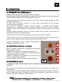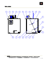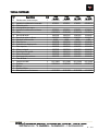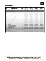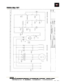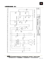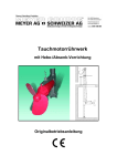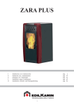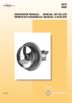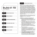
1
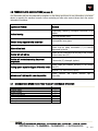
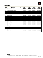
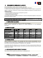
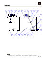
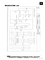
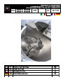
manuale d’istruzioni Instruction manual / Guide d'instructions Bedienungsanleitung / Manual de instrucciones Code IT 6560 6562 6564 6566 Matr Rev 20131203 Miscelatore per Miele 02 EN Honey Blender 11 FR Mélangeur à Miel 20 DE Honig-Rührmaschine 29 1.0 AVVERTENZE GENERALI SULLA SICUREZZA LEGGERE ATTENTAMENTE QUESTO MANUALE PRIMA D’UTILIZZARE LA MACCHINA Questo libretto e' parte integrante della macchina e l'accompagna fino alla demolizione. La macchina presenta parti pericolose perchè allacciata alla rete elettrica e dotata di movimento, pertanto possono causare gravi danni a persone o cose: - un uso improprio la rimozione delle protezioni e lo scollegamento dei dispositivi di protezione la mancanza d’ispezioni e manutenzioni la manomissione dell’impianto elettrico Le istruzioni devono essere integrate ed aggiornate in base alle disposizioni legislative e dalle norme tecniche di sicurezza vigenti. La ditta costruttrice non si riterrà responsabile d’inconvenienti, rotture o incidenti dovuti al mancato rispetto o alla non applicazione delle indicazioni contenute nel presente manuale. 1.1 IDENTIFICAZIONE DELLA MACCHINA Miscelatore per miele con funzionamento ad elica marina montata su asse inclinato. Macchina costruita conformemente ai requisiti della direttiva 89/392/CEE e sue successive modifiche. 1.2 DATI TECNICI Capacità di miele Velocità di rotazione Motore elettrico trifase Motore elettrico monofase Resistenza elettrica Ingombro al suolo Altezza totale Peso kg /min’ w w w mm mm kg n 250 50 550 550 1650 725 x 725 1610 102 600 50 1150 1150 1650 913 x 913 1315 120 1000 50 1150 1150 3000 1052 x 1052 1410 165 2000 50 1150 1150 3000 1272 x 1272 1770 198 1.3 PERSONALE ADDETTO AI FINI DELLA SICUREZZA QUESTA MACCHINA DEVE ESSERE UTILIZZATA ESCLUSIVAMENTE DA PERSONALE ADULTO IL QUALE DEVE ESSERE INFORMATO DELLE ISTRUZIONI CONTENUTE IN QUESTO MANUALE, CHE COSTITUISCE PARTE INTEGRANTE ED ESSENZIALE DELLA MACCHINA. Le operazioni vanno svolte da una sola persona. Altro personale che dovesse svolgere operazioni di carico o svuotamento del recipiente, deve essere informata delle norme di sicurezza contenute in questo manuale. 1.4 AVVERTENZE / USO PREVISTO E NON PREVISTO Questa macchina deve essere impiegata esclusivamente per la miscelazione di miele. La resistenza utilizzata è adatta per l'esclusivo riscaldamento di acqua. La temperatura impostata non deve superare i 50°C per non danneggiare il miele. Costruzioni Apistiche – via Maestri del Lavoro 23 – 48018 Faenza www.legaitaly.com - Tel 054626834 – Fax 054628279 – P.iva 00043230390 2 / 40 La ditta costruttrice non si riterrà responsabile di inconvenienti, rotture o incidenti dovuti all'uso improprio e al non rispetto delle indicazioni contenute nel presente manuale. Non manomettere l'impianto elettrico. 2.1 MOVIMENTAZIONE / TRASPORTO La macchina è normalmente stabile e non richiede particolari attenzioni nel carico o nello spostamento. Il sollevamento va effettuato dal basso. Le forche del carrello elevatore devono sporgere all'esterno del diametro del recipiente. Qualora la macchina dovesse essere fissata con corde, è bene proteggere le zone di passaggio di queste, valutando il rischio di deformazione del recipiente o danneggiamento dei coperchi. 2.2 INSTALLAZIONE (rif. pag. 8) La macchina deve essere posta sul proprio basamento prestando attenzione che sia posizionata in condizioni di assoluta stabilità e riferita all'interno degli appoggi. Il pavimento deve avere una portanza proporzionata alla massa totale a pieno carico. Si consiglia che, per un raggio di circa un metro attorno al miscelatore, rimanga spazio libero per un comodo svolgimento della lavorazione. Qualora il miscelatore fosse posto in alto, si dovrà provvedere a disporre di una passerella di ispezione e lavoro, autoportante, con un piano di calpestio ad un livello inferiore di almeno mt.1,1 rispetto al bordo di carico del miscelatore. Per motivi di sicurezza, non utilizzare scale a pioli né tanto meno appoggiarle al miscelatore o al suo supporto. Sul recipiente vanno avvitati il rubinetto (22) di carico/scarico (quello per il liquido dell' intercapedine) e la resistenza (21). Utilizzare nel montaggio prodotti per la giunzione di collegamenti idraulici per garantire una efficace tenuta. LO SFIATO DELL'INTERCAPEDINE (6) DEVE ESSERE SEMPRE LASCIATO APERTO; EVITARE CHE QUALSIASI OGGETTO POSSA OSTACOLARE LA LIBERA CIRCOLAZIONE DELL'ARIA. Una pressione superiore a quella atmosferica potrebbe fare implodere il recipiente interno con danni irreparabili. Il motoriduttore e la resistenza elettrica sono dotati di cavo d'allacciamento monofase (lungo mt.3 ca.) con spina pronta per l'allacciamento a corrente monofase 220V 50Hz, oppure trifase 380V 50Hz. L'allacciamento può essere effettuato solo ad una regolamentare presa elettrica di sicurezza. Il valore d'allacciamento è di 1100 W per il motore del miscelatore e di 1650 W per la resistenza elettrica. Per aumentare la sicurezza si consiglia di preporre alla macchina un interruttore differenziale con corrente di stacco di 30mA; la conduttura elettrica deve essere protetta mediante una valvola automatica 16A. E' consigliabile che la struttura metallica di supporto sia collegata a massa. Un microinterruttore di sicurezza (1) impedisce il funzionamento del miscelatore a coperchio sollevato, ma non esclude tensione alla resistenza elettrica. La rotazione delle pale deve essere in senso orario. 2.3 DESCRIZIONE Per ottenere una buon risultato nella miscelazione del miele è bene conoscere la tecnologia del miele in generale ed anche le caratteristiche specifiche dei mieli che si dovranno miscelare. Non tutti i mieli sono compatibili fra di loro per ottenere un prodotto omogeneo. Costruzioni Apistiche – via Maestri del Lavoro 23 – 48018 Faenza www.legaitaly.com - Tel 054626834 – Fax 054628279 – P.iva 00043230390 3 / 40 Una buona macchina per miscelare deve avere delle caratteristiche che rendano il lavoro efficace e rapido, che non agiti violentemente il prodotto e soprattutto non gli permette di inglobare aria. Anche la tecnica dell'inseminazione del miele, necessita di una macchina che omogeneizzi bene i composti e possa frantumare e sciogliere i blocchi semidensi immessi per la miscelazione. Grazie alle soluzioni tecniche da anni validamente sperimentate, il miscelatore "Lega" si presenta con i requisiti richiesti. Il miscelatore è composto da un recipiente in acciaio inossidabile con intercapedine e fondo a scarico totale frontale, con rubinetto a sfera. L'intercapedine, in cui va immessa l'acqua, è riscaldata da una resistenza elettrica termostatata con lo scopo di mantenere fluida la massa del miele. La miscelazione è ottenuto mediante due pale a elica marina montate su albero inclinato e movimentate da un motoriduttore. Un coperchio incernierato chiude superiormente il miscelatore. 3.0 REGOLAZIONE E MESSA A PUNTO INIZIALE DELLA MACCHINA (rif. pag. 8) Prima dell'utilizzazione, ad alimentazione elettrica disinserita, il recipiente va lavato all'interno con acqua calda o, meglio, con detergenti neutri e asciugato. Per questa operazione può essere necessario aprire anche il semicoperchio fisso; a lavaggio concluso è importante, ai fini della sicurezza, fissarlo nuovamente nella sua posizione. Riempimento dell'intercapedine Nell'intercapedine va immessa acqua che sia possibilmente demineralizzata per evitare che nel tempo, il deposito del calcare possa danneggiare il rendimento della resistenza. E' consigliabile che l'introduzione venga effettuata, mediante un tubo flessibile, dal rubinetto posto inferiormente: la fuoriuscita dell'aria avviene così attraverso lo sfiato posto in alto. Considerando che il calore aumenta il volume dell'acqua, l'intercapedine non deve essere riempita totalmente. Riscaldamento La resistenza elettrica è dotata di termostato; si fa notare che il suo grado di scostamento nella rilevazione dell'escursione termica è di alcuni gradi. In caso sia richiesta una maggiore precisione, è opportuno fare un rilevamento diretto della temperatura sul prodotto L'accensione della resistenza è comandata dal termostato (21) regolato dal pomello posto sulla scatola; la luce spia a fianco ne segnala il funzionamento. Quando la temperatura impostata è stata raggiunta, la resistenza si spegne e in contemporaneo, la spia. Per poter sfruttare il vantaggio del recipiente riscaldato, è bene che l'accensione del riscaldamento sia effettuata alcune ore prima dell'utilizzo della macchina. La temperatura dell'intercapedine (35-45°C necessaria per il miele) non giustifica una coibentazione esterna né per ragioni di sicurezza né per la dispersione di calore, essendo piccolo lo scarto nei confronti della temperatura ambiente del laboratorio. La coibentazione diventa indispensabile in caso di impostazione di temperature più elevate. La resistenza deve sempre lavorare immersa in acqua, per cui occorre verificare sempre il livello dell'acqua, prima di inizio lavoro. Costruzioni Apistiche – via Maestri del Lavoro 23 – 48018 Faenza www.legaitaly.com - Tel 054626834 – Fax 054628279 – P.iva 00043230390 4 / 40 4.0 ISTRUZIONI D’USO 4.1 PREPARAZIONE PER IL LAVORO (rif. pag. 8) All'inizio del lavoro verificare che la valvola di scarico (14) sia chiusa. Introdurre le partite di miele versandole dall'apertura superiore; utilizzando la pompa il miele può essere anche essere introdotto dalla valvola di scarico opportunamente collegata. Il livello del prodotto nel recipiente deve restare circa 100 mm al disotto del bordo superiore per evitare fuoriuscite durante il lavoro. Per evitare rischi di emulsione, verificare che le pale, anche nella posizione più alta, rimangano completamente immerse nel miele. Se ciò non fosse, modificare la posizione della pala superiore (11) facendola scorrere sull'albero, abbassandola fino a raggiungere la posizione necessaria, alzandola per evitare che tocchi il prodotto e lasciando il compito di miscelazione solo a quella inferiore, qualora il miele da lavorare fosse in piccola quantità. La minima quantità miscelabile è data da un livello di prodotto tale che almeno la pala inferiore sia completamente immersa in ogni posizione del giro. La pala inferiore (13) non deve essere abbassata per evitare che urti sul fondo del recipiente. Il tempo della miscelazione varia a seconda del prodotto immesso. Mieli già molto fluidi si miscelano in pochi minuti, se in altre condizioni non sono comunque di norma necessari più di 30 minuti. Controllare saltuariamente il livello dell'acqua nell'intercapedine e ripristinarlo qualora fosse necessario A 4.2 ISTRUZIONI PER L’USO (rif. fig. 1) (rif. pag. 8) Dopo aver regolato la temperatura da raggiungere sul termostato della resistenza (21- Pag.8) 1 Allacciare il miscelatore ad una regolamentare presa elettrica. 2 Verificare che il pulsante di emergenza (A) sia sbloccato e ruotare l’interruttore generale (D) in posizione ‘1’. 3 Ruotare il selezionatore del riscaldamento (B) verso destra, per iniziare il riscaldamento delle resistenze. 4 Premere il pulsante di rotazione (C) per iniziare la miscelazione. 5.0 MANUTENZIONE (rif. pag. 8) B C fig.1 D LE OPERAZIONI DI MANUTENZIONE VANNO ESEGUITE A MACCHINA FERMA E A COLLEGAMENTI ELETTRICI DISINSERITI. Alla fine del lavoro la macchina deve essere lavata esclusivamente con acqua tiepida ed asciugata con un panno di cotone. Se si prevede che la macchina debba rimanere inutilizzata per parecchio tempo, provvedere a verificare la stato dei componenti meccanici ad eventuali lavori di revisione, sostituzione o manutenzione per avere la macchina nelle migliori condizioni per l'utilizzo successivo. Costruzioni Apistiche – via Maestri del Lavoro 23 – 48018 Faenza www.legaitaly.com - Tel 054626834 – Fax 054628279 – P.iva 00043230390 5 / 40 Il motoriduttore (2) non richiede manutenzioni. Controllare il livello dell'acqua nell'intercapedine e ripristinarla se necessario. Verificare lo stato dell'anello in nylon (15) posto in fondo all'albero che porta le pale. L'albero porta pale non è bloccato al riduttore, quindi si può sollevare e sfilare dal riduttore facilmente. Per un periodo di lunga inattività è consigliabile ungere con un velo d'olio di paraffina le parti cromate e ricoprire la macchina con un telo. 6.0 POSSIBILI INCONVENIENTI E LORO SOLUZIONE (rif. pag. 8) In caso di necessità, il nostro personale tecnico è a Vostra disposizione per comunicazione telefonica o mezzo fax, negli orari di lavoro, per qualunque informazione o consiglio tecnico relativo alla macchina; comunque prima di interpellarci, Vi preghiamo di controllare le informazioni sotto riportate. Problema Riscontrato Soluzione Schiuma in superficie Emulsione dovuta alla non completa immersione delle pale Miscelazione troppo prolungata Separazione del miele miscelato dopo un certo Mieli incompatibili periodo Agitatore che non parte Controllare che il micro di sicurezza (1) sia premuto correttamente dal coperchio La resistenza non si accende Controllare che ci sia continuità di linea dalla spina fino ai contatti nella scatola della resistenza (21) La resistenza continua a riscaldare oltre la temperatura indicata Termostato (21) danneggiato (da sostituire) L'accensione dell'impianto di riscaldamento fa scattare il differenziale Controllare il buono stato del cavo e dei contatti nella scatola della resistenza (21) Resistenza (19) in corto circuito (da sostituire) La luce spia non si accende anche a resistenza funzionante Controllare i contatti ed eventualmente sostituirla 6.1 RICAMBI CONSIGLIATI PER 2 ANNI DI LAVORO CONTINUATO Descrizione Quantità Pala ad elica Impianto di riscaldamento Microinterruttore di sicurezza Lampada spia Termostato capillare Cerniera coperchio 1 1 1 1 1 1 Costruzioni Apistiche – via Maestri del Lavoro 23 – 48018 Faenza www.legaitaly.com - Tel 054626834 – Fax 054628279 – P.iva 00043230390 6 / 40 VISTA LATERALE Costruzioni Apistiche – via Maestri del Lavoro 23 – 48018 Faenza www.legaitaly.com - Tel 054626834 – Fax 054628279 – P.iva 00043230390 7 / 40 TABELLA PARTICOLARI Rif 22 21 20 19 18 17 16 15 14 13 12 11 10 9 8 7 6 5 4 3 2 1 Descrizione Valvola carico scarico acqua Impianto riscaldamento termostato Serbatoio miele Intercapedine con acqua Impianto riscaldamento resistenza Sfera Boccola di fondo Boccola in nylon su albero Valvola di scarico miele Pala inferiore Contenitore a doppia parete Pala superiore Albero portapale Semicoperchio apribile Sbarra trasversale Semicoperchio posteriore Tubo di sfiato Cerniera a scatto Riduttore Motore Quadro elettrico Microinterruttore di sicurezza Q.tà 1 1 1 1 1 1 1 1 1 1 1 1 1 1 1 1 1 2 1 1 1 1 6560 kg 250 65560050 6700601 6562 kg 600 65560075 6700601 6564 kg 1000 65560075 6700601 6566 kg 2000 65560075 65560075 6700601 62900008 6560300 6560355 6400 6560600 6560100 6560600 6560350 6560410 6560200 6560420 6700601 62900008 6560300 6560355 6400 6560600 6562100 6560600 6562350 6562410 6562200 6562420 6700601 62900008 6560300 6560355 6400 6560600 6564100 6560600 6564350 6564410 6564200 6564420 6700601 62900008 6560300 6560355 6400 6560600 6566100 6564600 6566350 6566410 6566200 6566420 82112000 65000049 82112000 65000062 82112000 65000062 82112000 65000062 41101022 41101022 41101022 41101022 Costruzioni Apistiche – via Maestri del Lavoro 23 – 48018 Faenza www.legaitaly.com - Tel 054626834 – Fax 054628279 – P.iva 00043230390 8 / 40 IMPIANTO ELETTRICO - parte 1 Costruzioni Apistiche – via Maestri del Lavoro 23 – 48018 Faenza www.legaitaly.com - Tel 054626834 – Fax 054628279 – P.iva 00043230390 9 / 40 IMPIANTO ELETTRICO - parte 2 Costruzioni Apistiche – via Maestri del Lavoro 23 – 48018 Faenza www.legaitaly.com - Tel 054626834 – Fax 054628279 – P.iva 00043230390 10 / 40 1.0 GENERAL SAFETY DIRECTIONS READ THIS MANUAL THROUGHOUT BEFORE USING THE MACHINE This handbook forms an integral part of the machine and should be kept with it throughout its working life. The machine includes dangerous electrically live and moving parts, which can cause serious damages to persons or property in case of: incorrect use removal of guards or disconnection of safety devices poor inspection and servicing tampering with the electric system These directions must be completed and updated according to applicable legal provisions and technical safety standards. The manufacturer may not be held responsible for failures, breaks or accidents resulting from incorrect use of the machine or failure to follow the directions contained in this manual. 1.1 IDENTIFICATION OF THE MACHINE Honey blender with marine propellers fitted on an inclined shaft. Machine built according to the requirements of the Directive 89/392/EEC and its subsequent amendments. 1.2 SPECIFICATIONS Honey capacity Rotation speed Three-phase electric motor Single-phase electric motor Electric resistor Overall dimensions Total height Weight kg /min’ w w w mm mm kg n 250 50 550 550 1650 725 x 725 1610 102 600 50 1150 1150 1650 913 x 913 1315 120 1000 50 1150 1150 3000 1052 x 1052 1410 165 2000 50 1150 1150 3000 1272 x 1272 1770 198 1.3 MACHINE OPERATORS FOR SAFETY PURPOSES THIS MACHINE MUST BE USED BY SKILLED PERSONNEL ONLY, AWARE OF THE INSTRUCTIONS CONTAINED IN THIS HANDBOOK WHICH FORMS AN INTEGRAL PART OF THE MACHINE. Machine operations should be carried out by a single person. Any other personnel in charge of tank filling or emptying should be aware of the safety information contained in this manual. 1.4 NOTICES/RECOMMENDED/NOT RECOMMENDED USE This machine should be exclusively used for honey blending. The resistor used is exclusively suitable for water heating. The pre-set temperature should not exceed 50°C not to alter the honey. The manufacturer may not be held responsible for failures, breaks or accidents resulting from incorrect use of the machine or failure to follow the safety directions in this handbook. Do not tamper with the electric system. Costruzioni Apistiche – via Maestri del Lavoro 23 – 48018 Faenza www.legaitaly.com - Tel 054626834 – Fax 054628279 – P.iva 00043230390 11 / 40 2.1 HANDLING/TRANSPORT The machine is normally stable and does not need any special precautions during loading or handling. Lifting must be done from the bottom. The lift truck forks must protrude from the outside of the tank. If the machine must be secured with cables, protect the cable route to prevent damaging the tank or lids. 2.2 INSTALLATION (see page 8) The machine must be placed on its base checking that it is perfectly stable and centred on its supports. The floor load-bearing capacity must be proportional to the total weight under full load conditions. We advise to leave sufficient operating space (approximately one metre in radius around the blender) to be able to work comfortably. If the blender is installed at a height above the floor, an inspection and working gangway must be provided, which must be self-supported and have a walk-on surface lower by at least 1.1 m with respect to the blender loading rim. For safety reasons, ladders should not be used. It is forbidden in particular to place ladders against the blender or its support. The inlet/outlet tap (22) (for the interspace liquid) and the resistor (21) must be screwed on to the blender. During installation, use hydraulic coupling sealants to ensure effective tightness. THE INTERSPACE VENT (6) MUST ALWAYS BE LEFT OPEN; MAKE SURE THAT THERE AREN’T ANY FOREIGN OBJECTS PREVENTING FREE AIR CIRCULATION. A pressure value exceeding the atmospheric pressure might cause the internal tank to implode causing irreparable damage. The gearmotor and resistor have an approximately 3 m long connection cable ready for plugging into a 220V 50Hz single phase outlet or a 380V 50Hz three-phase current one. Connection is only possible if an electric outlet up to safety standards is used. The connection value is 1100 W for the blender motor and 1650 W for the resistor. To improve safety, we advise to install a differential switch with 30mA release current upstream from the machine; the electric lines must be protected by a 16A automatic valve. It is advisable to carry out metal support structure grounding. A safety microswitch (1) prevents the blender from starting with a lifted lid, without however cutting input to the resistor. The blades must turn clockwise. 2.3 DESCRIPTION To obtain satisfactory honey blending results, the user should be familiar with honey technology in general and with the specific characteristics of the honey types to blend. Not all honey types are compatible and allow a homogeneous product to be obtained by blending. A good blending machine must have characteristics that make work quick and effective, without stirring the honey too hard and above all, without incorporating any air in the product. The honey insemination technique also requires perfect machine homogenizing of the mix and breaking of any semi-thick lumps added for blending. Thanks of technical expertise acquired over the years, the Lega blender has all the necessary requirements. Costruzioni Apistiche – via Maestri del Lavoro 23 – 48018 Faenza www.legaitaly.com - Tel 054626834 – Fax 054628279 – P.iva 00043230390 12 / 40 It consists of a stainless steel tank with an interspace and a full discharge bottom and ball valve gate. The interspace in which water must be added is heated by a resistor equipped with a thermostat to keep the honey mass fluid. Blending is obtained with two marine propeller blades mounted on an inclined shaft and driven by a gearmotor. A hinged lid is used to close the blender at the top. 3.0 MACHINE ADJUSTMENT BEFORE START-UP (see page 8) Before using the blender, and after disconnecting electric power, wash the inside of the tank with hot water or better still, with a mild detergent, then wipe it dry. To do this, it may be necessary to open the fixed half-lid, too; after completing the washing cycle secure the lid back in its safety position. Filling the interspace The interspace must be filled with preferably demineralised water to prevent lime scale deposits from affecting the resistor efficiency. Add water through a flexible hose from the tap located in the bottom part: in this way, air will be let out through the top vent. As heating will increase the water volume, the interspace should not be filled up completely. Heating The electric resistor is equipped with a thermostat; note that the extent of the deviation in the measurement of temperature differences is of a few degrees. If higher accuracy is requested, a direct measurement of the product temperature should be carried out. The resistor operation is controlled by the thermostat (21), adjustable via the knob on the box; the indicator light next to it signals its operation. When the pre-set temperature is achieved, the resistor will go off and the indicator light then goes off, too. To make the most out of the heated tank, heating should be turned on a few hours before starting to use the machine. The temperature reached in the interspace (35-45°C required for honey processing) is not so high as to justify external insulation for safety or heat dissipation purposes, given the small difference between this temperature and the lab ambient temperature. Heat insulation, however, is necessary if higher temperatures are set. The resistor should always work immersed in water: always check the water level before beginning to work. 4.0 OPERATING INSTRUCTIONS 4.1 PREPARING FOR WORK (see page 8) Before beginning to work, make sure that the outlet valve (14) is closed. Add honey batches by pouring in from the top opening; by using the pump, it is also possible to feed honey to the machine via the suitably connected outlet valve. The product level in the tank must be approximately 100 mm below the top edge to prevent spills during work. To prevent emulsifying, check that the propeller blades are always completely covered with honey, even in the top position. Costruzioni Apistiche – via Maestri del Lavoro 23 – 48018 Faenza www.legaitaly.com - Tel 054626834 – Fax 054628279 – P.iva 00043230390 13 / 40 If it is not so, adjust the top blade position (11) causing it to slide on the shaft, and lower it to reach the required position, or lift it to prevent contact with the honey leaving the bottom blade only in charge of blending, if a reduced amount of honey must be processed. The minimum blending quantity is given by a product level ensuring that at least the bottom blade is completely immersed in honey throughout the rotation cycle. The bottom blade (13) should not be lowered to prevent it hitting the bottom of the tank. The blending time changes according to the product to process. Highly fluid honeys can be blended in only a few minutes, other thicker types may require up to 30 minutes. Regularly check the water level in the interspace and top up if required. A 4.2 INSTRUCTIONS FOR USE (see fig. 1) (see page 8) After setting the temperature to reach on the resistor thermostat (21Page 8): 1 Plug the blender into a standard electric outlet. 2 Check that the emergency button (A) is not depressed and turn the main switch (D) to position ‘1’. 3 Turn the heating selector switch (B) to the right to control resistor heating. 4 Press the rotating button (C) to start blending. B C D fig.1 5.0 MAINTENANCE (see page 8) MAINTENANCE OPERATIONS SHOULD BE CARRIED OUT AFTER STOPPING THE MACHINE AND DISCONNECTING ALL ELECTRIC CIRCUITS. After work wash the machine exclusively with warm water and wipe it dry with a cotton cloth. If you expect not to use the machine for a prolonged period of time, check its mechanical components’ efficiency and carry out any inspection, replacement or maintenance operations required to ensure that the machine is in the best condition for any subsequent use. The gearmotor (2) is maintenance-free. Check the water level in the interspace and top up if necessary. Check the state of repair of the nylon ring (15) at the foot of the propeller shaft. The propeller shaft is not fastened to the gearmotor, therefore, it can be easily lifted and removed. Before a prolonged period of inactivity, we advise to coat all chrome plated parts with a film of paraffin oil and cover the machine with a tarpaulin. Costruzioni Apistiche – via Maestri del Lavoro 23 – 48018 Faenza www.legaitaly.com - Tel 054626834 – Fax 054628279 – P.iva 00043230390 14 / 40 6.0 POSSIBLE FAULTS AND SOLUTIONS (see page 8) Our After-sales staff can be contacted by telephone or fax during work hours for any information or technical advice in regard to the machine; however, before contacting our after-sales service please check the service information here below. Experienced Problem Solution Surface foaming Emulsifying caused by incomplete immersion of the blades Too long blending cycle Blended honey separation after some time Incompatible honey types Stirrer will not start Check that the safety microswitch (1) is correctly depressed by the lid Resistor will not light up Check for line continuity from the plug to the contacts in the resistor box (21) Resistor will overheat exceeding the pre-set temperature Thermostat (21) damaged (replace) Heating system operation triggers differential switch Check cable and contacts efficiency in the resistor box (21) Resistor (19) short circuit (replace) Indicator won’t light up with a working resistor Check contacts and replace indicator light if necessary 6.1 RECOMMENDED SPARE PARTS FOR 2 YEARS OF CONTINUOUS OPERATION Description Quantity Propeller blade Heating system Safety microswitch Indicator light Capillary thermostat Lid hinge 1 1 1 1 1 1 Costruzioni Apistiche – via Maestri del Lavoro 23 – 48018 Faenza www.legaitaly.com - Tel 054626834 – Fax 054628279 – P.iva 00043230390 15 / 40 SIDE VIEW Costruzioni Apistiche – via Maestri del Lavoro 23 – 48018 Faenza www.legaitaly.com - Tel 054626834 – Fax 054628279 – P.iva 00043230390 16 / 40 PARTS TABLE Ref 22 21 20 19 18 17 16 15 14 13 12 11 10 9 8 7 6 5 4 3 2 1 Descr iption Water inlet outlet valve Thermostat heating system Honey tank Interspace with water Resistor heating system Ball Bottom bushing Nylon bushing on shaft Honey outlet valve Lower blade Double walled tank Upper blade Blade shaft Opening half lid Cross bar Rear half lid Venting tube Snap hinge Reduction gear Motor Control panel Safety microswitch Qty 1 1 1 1 1 1 1 1 1 1 1 1 1 1 1 1 1 2 1 1 1 1 6560 kg 250 65560050 6700601 6562 kg 600 65560075 6700601 6564 kg 1000 65560075 6700601 6566 kg 2000 65560075 65560075 6700601 62900008 6560300 6560355 6400 6560600 6560100 6560600 6560350 6560410 6560200 6560420 6700601 62900008 6560300 6560355 6400 6560600 6562100 6560600 6562350 6562410 6562200 6562420 6700601 62900008 6560300 6560355 6400 6560600 6564100 6560600 6564350 6564410 6564200 6564420 6700601 62900008 6560300 6560355 6400 6560600 6566100 6564600 6566350 6566410 6566200 6566420 82112000 65000049 82112000 65000062 82112000 65000062 82112000 65000062 41101022 41101022 41101022 41101022 Costruzioni Apistiche – via Maestri del Lavoro 23 – 48018 Faenza www.legaitaly.com - Tel 054626834 – Fax 054628279 – P.iva 00043230390 17 / 40 ELECTRIC SYSTEM - part 1 Costruzioni Apistiche – via Maestri del Lavoro 23 – 48018 Faenza www.legaitaly.com - Tel 054626834 – Fax 054628279 – P.iva 00043230390 18 / 40 ELECTRIC SYSTEM - part 2 Costruzioni Apistiche – via Maestri del Lavoro 23 – 48018 Faenza www.legaitaly.com - Tel 054626834 – Fax 054628279 – P.iva 00043230390 19 / 40 1.0 RECOMMANDATIONS GÉNÉRALES SUR LA SÉCURITÉ LIRE ATTENTIVEMENT CE GUIDE AVANT D'UTILISER LA MACHINE Ce guide fait partie intégrante de la machine et l'accompagne jusqu'à sa démolition. La machine présente des parties dangereuses car elle est branchée au réseau électrique et comprend des organes en mouvement, elle peut donc causer de graves dommages aux personnes ou aux biens dans les situations suivantes : - une utilisation impropre ; le retrait des protections et le débranchement des dispositifs de protection le manque d'inspections et de maintenance ; la modification de l'installation électrique. Les instructions doivent être complétées et actualisées en fonction des dispositions législatives et des normes techniques de sécurité en vigueur. Le constructeur ne sera aucunement responsable en cas de problèmes, ruptures ou accidents dus au non-respect ou à la non-application des recommandations contenues dans ce guide. 1.1 IDENTIFICATION DE LA MACHINE Mélangeur à Miel avec fonctionnement ad hélice mari monter à une seule paroi. Machine construite conformément aux exigences de la directive 89/392/CEE et à ses modifications successives. 1.2 DONNÉES TECHNIQUES Contenance en miel Vitesse de rotation Moteur électrique triphasé Moteur électrique monophasé Résistance électrique Encombrement au sol Hauteur totale Poids kg min’ W W 250 50 550 550 600 50 1150 1150 1000 50 1150 1150 2000 50 1150 1150 W mm mm kg 1650 725 x 725 1610 102 1650 913 x 913 1315 120 3000 1052 x 1052 1410 165 3000 1272 x 1272 1770 198 n/ 1.3 PERSONNEL PRÉPOSÉ AFIN DE GARANTIR LA SÉCURITÉ, CETTE MACHINE DOIT ÊTRE UTILISÉE EXCLUSIVEMENT PAR DU PERSONNEL ADULTE QUI DOIT ÊTRE À CONNAISSANCE DES INSTRUCTIONS CONTENUES DANS CE GUIDE, QUI CONSTITUE UNE PARTIE INTÉGRANTE ET ESSENTIELLE DE LA MACHINE. Les opérations doivent être effectuées par une seule personne. Si d’autres personnes devaient effectuer des opérations de chargement et vidage du récipient, elles devront être mises au courant des normes de sécurité contenues dans ce guide. 1.4 AVERTISSEMENTS/UTILISATION PRÉVUE ET NON PRÉVUE Cette machine doit être employée exclusivement pour le mélangeage du miel. Costruzioni Apistiche – via Maestri del Lavoro 23 – 48018 Faenza www.legaitaly.com - Tel 054626834 – Fax 054628279 – P.iva 00043230390 20 / 40 La résistance utilisée est exclusivement adaptée pour chauffer l'eau . La température sélectionnée ne doit pas dépasser 50 °C pour ne pas endommager le miel. Le constructeur ne sera aucunement responsable en cas de problèmes, ruptures ou accidents dus à une utilisation impropre et au non-respect des recommandations contenues dans ce guide. Ne pas modifier l'installation électrique. 2.1 MANUTENTION/TRANSPORT La machine est normalement stable et ne nécessite pas de précautions particulières lors de son chargement et de son déplacement Son soulèvement doit avoir lieu par le bas. Les fourches du chariot doivent dépasser à l'extérieur du diamètre du récipient. Si la machine est fixée à l'aide de cordes, il faut protéger les endroits de leur passage sur la machine en évaluant le risque de déformation du récipient ou d'endommagement des couvercles. 2.2 INSTALLATION (réf. page 8) La machine doit être placée sur son embase en faisant attention qu’elle soit positionnée en conditions de stabilité absolue et centrée dans ses appuis. Le plancher doit avoir une portance proportionnée à la masse totale à pleine charge. Il est conseillé de laisser un espace libre d'au moins un mètre autour du mélangeur pour que le travail puisse se dérouler aisément. Si le mélangeur est placé en hauteur, il faudra installer une passerelle d’inspection et de travail, autoporteuse, avec un plancher à un niveau inférieur d’au moins 1,1 m par rapport au bord de chargement du mélangeur. Pour des raisons de sécurité, ne pas utiliser d’escaliers à barreaux et ne pas les appuyer au mélangeur ou à son support. Sur le récipient il faudra visser le robinet (22) de chargement/déchargement (pour le liquide du bain-marie) et la résistance (21). Pour le montage utiliser des joints pour les raccordements hydrauliques afin de garantir une bonne étanchéité. L'ÉVENT DE L'INTERSTICE DU BAIN MARIE (6) DOIT TOUJOURS RESTER OUVERT ; ÉVITER QU'UN OBJET QUEL QU'IL SOIT EMPÊCHE L'AIR DE CIRCULER LIBREMENT. Une pression supérieure à la pression atmosphérique pourrait faire imploser le récipient interne causant des dommages irréparables. Le motoréducteur et la résistance électrique sont équipés de câble de raccordement monophasé (de 3 m de longueur environ) avec une fiche adaptée à un courant monophasé de 220 V 50 Hz. ou bien triphasé de 380 V 50 Hz. Le branchement ne peut être effectué que dans une prise électrique de sécurité règlementaire. La valeur de branchement est de 1100 W pour le moteur du mélangeur et de 1650 W pour la résistance électrique. Pour accroitre la sécurité, il est conseillé de positionner en amont de la machine un disjoncteur différentiel avec un courant de déclenchement de 30 mA ; la ligne électrique doit être protégée par un fusible automatique de 16 A. Il est conseillé de raccorder à la masse la structure métallique de support. Un micro-interrupteur de sécurité (1) empêche le fonctionnement du mélangeur quand le couvercle est soulevé, mais ne coupe pas le courant à la résistance électrique. La rotation des pales doit se faire dans le sens des aiguilles d’une montre. Costruzioni Apistiche – via Maestri del Lavoro 23 – 48018 Faenza www.legaitaly.com - Tel 054626834 – Fax 054628279 – P.iva 00043230390 21 / 40 2.3 DESCRIPTION Pour obtenir un bon résultat lors du mélange du miel il est préférable de connaître la technologie du miel en général ainsi que les caractéristiques spécifiques des miels qui devront être mélangés. Tous les miels ne sont pas compatibles entre eux pour obtenir un produit homogène. Une bonne machine de mélangeage doit avoir des caractéristiques qui rendent le travail efficace et rapide, ne pas secouer violemment le produit et éviter qu’il englobe de l’air. La technique de l'ensemencement du miel, nécessite d’une machine qui homogénéise bien les composants et puisse concasser et fondre les blocs semi-denses introduits pour le mélangeage. Grâce aux solutions techniques expérimentées avec succès depuis des années, le mélangeur « Lega » est conforme aux exigences requises. Le mélangeur est composé d’un récipient en acier inoxydable, avec un interstice pour le bain-marie et un fond à évacuation totale frontale, avec robinet à bille. Le bain-marie dans lequel doit être placée l'eau, est chauffé par une résistance électrique thermostatée dans le but de maintenir la fluidité de la masse de miel. Le mélangeage s’effectue à l’aide de deux pales à hélice marine montées sur un arbre incliné et actionnées par un motoréducteur. Un couvercle fixé par des charnières ferme la partie supérieure du mélangeur. RÉGLAGE ET PREMIÈRE MISE AU POINT DE LA MACHINE (réf. page 8) Avant l’utilisation, avec l'appareil débranché du réseau électrique, laver l'intérieur du récipient avec de l’eau chaude ou mieux encore des détergents neutres puis l’essuyer. Pour cette opération il pourrait aussi être nécessaire d’ouvrir le demi-couvercle fixe ; au terme du lavage il est important, aux fins de la sécurité, de le fixer de nouveau dans sa position. Remplissage de l’interstice du bain-marie Dans l'interstice du bain-marie il faut placer l'eau si possible déminéralisée afin d'éviter qu'au fil du temps le dépôt de calcaire endommage le rendement de la résistance. Il est conseillé d’effectuer l’introduction à l’aide d'un tuyau flexible, directement à partir du robinet placé en dessous. la sortie de l'air a lieu par un évent placé en haut. La chaleur augmentant le volume de l’eau, l'interstice du bain-marie ne doit pas être totalement rempli. Chauffage La résistance électrique est munie d’un thermostat ; soulignons que la valeur d'excursion thermique relevée par la résistance peut être différente de quelques degrés par rapport à la réalité. Si vous souhaitez une majeure précision il faut relever la température directement sur le produit. L'allumage de la résistance est commandé par le thermostat (21) réglé par le bouton placé sur le boîtier ; le voyant témoin correspondant en signale le fonctionnement. Quand la température programmée est atteinte, la résistance s’éteint ainsi que le voyant. Pour pouvoir exploiter l’avantage du récipient réchauffé, il est conseillé d'allumer le chauffage plusieurs heures avant l'utilisation de la machine. La température du bain-marie (35-45 °C nécessaire pour le miel) n’a pas besoin d'une isolation extérieure, ni pour des raisons de sécurité, ni pour la dispersion de chaleur, puisque l'écart de température par rapport à la température ambiante de travail est réduit. L’isolation devient indispensable en cas de sélection de températures plus élevées. La résistance doit toujours travailler plongée dans l'huile, il faut donc toujours vérifier le niveau de l’eau, avant de commencer le travail. Costruzioni Apistiche – via Maestri del Lavoro 23 – 48018 Faenza www.legaitaly.com - Tel 054626834 – Fax 054628279 – P.iva 00043230390 22 / 40 4.0 INSTRUCTIONS D’UTILISATION 4.1 PRÉPARATION POUR LE TRAVAIL (réf. page 8) Au début du travail, vérifier que la vanne d’évacuation (14) est fermée. Introduire le miel en le versant par l'ouverture supérieure ; en utilisant la pompe, le miel peut aussi être introduit par la vanne d'évacuation connectée à cet effet. Le niveau du produit dans le récipient doit rester à environ 100 mm en dessous du bord supérieur pour éviter les fuites durant le travail. Pour éviter les risques d’émulsion, vérifier que les pales, même dans la position la plus haute, restent complètement plongées dans le miel. Si ce n'est pas le cas, modifier la position de la pale supérieure (11) en la faisant glisser sur l'arbre, en l'abaissant jusqu'à atteindre la position nécessaire, en la soulevant pour éviter qu’elle ne touche le produit et en laissant le rôle de mélangeuse à la pale inférieure uniquement , en cas de petite quantité de miel à traiter. La quantité minimum mélangeable correspond à un niveau de produit suffisant à plonger complètement la pale quelle que soit la position du tour. La pale inférieure (13) ne doit pas être baissée, afin d’éviter qu’elle ne heurte le fond du récipient. Le temps de mélangeage varie selon le produit introduit. Les miels qui sont déjà très fluides se mélangent en quelques minutes, pour tous les autres cas il ne faut toutefois jamais plus de 30 minutes. Contrôler de temps en temps le niveau de l’eau du bain-marie et en ajouter si nécessaire A 4.2 MODE D'EMPLOI (réf. page 8) Après voir réglé la température à atteindre sur le thermostat de la résistance (21- Page 8) 1 Brancher le mélangeur à une prise électrique règlementaire. 2 Vérifier que le bouton d'urgence (A) est débloqué et tourner l’interrupteur général (D) en position ‘1’. 3 Tourner le sélecteur du chauffage (B) vers la droite, pour commencer à chauffer les résistances. 4 Presser la touche de rotation (C) pour commencer à mélanger. 5.0 MAINTENANCE (réf. page 8) B C D fig. 1 LES OPÉRATIONS DE MAINTENANCE DOIVENT ÊTRE EFFECTUÉES AVEC LA MACHINE ARRÊTÉE ET DÉBRANCHÉE DU RÉSEAU ÉLECTRIQUE. À la fin du travail la machine doit être lavée exclusivement à l'eau tiède et essuyée avec un chiffon de coton. S'il est prévu de ne pas utiliser la machine pendant une longue période, vérifier l'état des composants mécaniques et effectuer les éventuels travaux de révision, remplacement ou maintenance afin de disposer d'une machine en parfait état lors de l'utilisation ultérieure. Le motoréducteur (2) n’a pas besoin de maintenance. Contrôler le niveau de l’eau du bain-marie et le rétablir si nécessaire. Costruzioni Apistiche – via Maestri del Lavoro 23 – 48018 Faenza www.legaitaly.com - Tel 054626834 – Fax 054628279 – P.iva 00043230390 23 / 40 Vérifier l’état de la bague en nylon (15) placée au bout de l'arbre qui porte les pales. L'arbre porte-pales n’est pas bloqué au réducteur, on peut donc le soulever et le faire sortir facilement du réducteur. Pour les longues périodes d’inactivité, il est conseillé d'appliquer une fine couche d’huile de paraffine sur les parties chromées et de recouvrir la machine d’une bâche. 6.0 PROBLÈMES POSSIBLES ET SOLUTIONS (réf. page 8) Si nécessaire, notre personnel technique est à votre disposition, par téléphone ou par fax, durant les horaires de travail, pour toute information ou tout conseil technique relatif à la machine ; néanmoins avant de nous contacter, nous vous prions de contrôler les informations ci-après. Problème Solution Émulsion due à l’immersion incomplète des pales Mousse en surface Mélangeage trop prolongé Séparation du miel mélangé après un certain temps Miels incompatibles Agitateur qui ne démarre pas Contrôler que le micro-interrupteur de sécurité (1) est correctement enfoncé par le couvercle La résistance ne s’allume pas Contrôler la présence de continuité de ligne de la fiche jusqu'aux contacts dans le boîtier de la résistance (21) La résistance continue à chauffer au-delà de la température indiquée Thermostat (21) endommagé (le remplacer) L'allumage du dispositif de chauffage déclenche le différentiel Contrôler le bon état du câble et des contacts dans le boîtier de la résistance (21) Résistance (19) en court-circuit (la remplacer) Le voyant témoin ne s’allume pas même quand la résistance fonctionne Contrôler les contacts et éventuellement la remplacer 6.1 PIÈCES DE RECHANGE CONSEILLÉES POUR 2 ANS DE TRAVAIL CONTINU Description Quantité Pale à hélice Système de chauffage Micro-interrupteur de sécurité Voyant témoin Thermostat à capillaire Charnière du couvercle 1 1 1 1 1 1 Costruzioni Apistiche – via Maestri del Lavoro 23 – 48018 Faenza www.legaitaly.com - Tel 054626834 – Fax 054628279 – P.iva 00043230390 24 / 40 VUE LATÉRALE Costruzioni Apistiche – via Maestri del Lavoro 23 – 48018 Faenza www.legaitaly.com - Tel 054626834 – Fax 054628279 – P.iva 00043230390 25 / 40 TABLEAU DES COMPOSANTS Rif 22 21 20 19 18 17 16 15 14 13 12 11 10 9 8 7 6 5 4 3 2 1 Descrizione Vanne d'évacuation eau Système de chauffage thermostat Réservoir miel Interstice bain-marie eau Système de chauffage résistance Bille Bague de fond Bague en nylon Vanne d'évacuation du miel Pale inférieure Récipient à double paroi Pale supérieure Arbre porte-pales Demi-couvercle ouvrant Barre transversale Demi-couvercle arrière Tube d'évent Charnière à déclic Réducteur Moteur Coffret électrique Micro-interrupteur de sécurité Q.tà 1 1 1 1 1 1 1 1 1 1 1 1 1 1 1 1 1 2 1 1 1 1 6560 kg 250 65560050 6700601 6562 kg 600 65560075 6700601 6564 kg 1000 65560075 6700601 6566 kg 2000 65560075 65560075 6700601 62900008 6560300 6560355 6400 6560600 6560100 6560600 6560350 6560410 6560200 6560420 6700601 62900008 6560300 6560355 6400 6560600 6562100 6560600 6562350 6562410 6562200 6562420 6700601 62900008 6560300 6560355 6400 6560600 6564100 6560600 6564350 6564410 6564200 6564420 6700601 62900008 6560300 6560355 6400 6560600 6566100 6564600 6566350 6566410 6566200 6566420 82112000 65000049 82112000 65000062 82112000 65000062 82112000 65000062 41101022 41101022 41101022 41101022 Costruzioni Apistiche – via Maestri del Lavoro 23 – 48018 Faenza www.legaitaly.com - Tel 054626834 – Fax 054628279 – P.iva 00043230390 26 / 40 INSTALLATION ÉLECTRIQUE - 1e partie Costruzioni Apistiche – via Maestri del Lavoro 23 – 48018 Faenza www.legaitaly.com - Tel 054626834 – Fax 054628279 – P.iva 00043230390 27 / 40 INSTALLATION ÉLECTRIQUE - 2e partie Costruzioni Apistiche – via Maestri del Lavoro 23 – 48018 Faenza www.legaitaly.com - Tel 054626834 – Fax 054628279 – P.iva 00043230390 28 / 40 1.0 ALLGEMEINE SICHERHEITSHINWEISE VOR BENUTZEN DER MASCHINE IST DIESES HANDBUCH AUFMERKSAM ZU LESEN Dieses Handbuch ist wesentlicher Bestandteil der Maschine und muss bis zur Verschrottung aufbewahrt werden. Die Maschine umfasst gefährliche und sich bewegende Teile und ist an das Stromnetz angeschlossen. Durch folgendes Verhalten können schwere Personen- und Sachschäden entstehen: - Unsachgemäße Benutzung Entfernung der Schutzvorrichtungen und Unterbrechung der Schutzmechanismen Unterlassen der Inspektionen und Wartungen Veränderung der elektrischen Anlage Die Anweisungen müssen gemäß der gesetzlichen Vorschriften und der gültigen technischen Sicherheitsrichtlinien vervollständigt und aktualisiert werden. Das Herstellerunternehmen übernimmt keine Haftung für Störungen, Beschädigungen oder Unfälle, die in Folge der Nichtbeachtung oder Nichtanwendung der Vorgaben dieses Handbuches entstehen. 1.1 MASCHINENBESCHREIBUNG Honig-Rührmaschine mit Rührpropeller auf geneigter Welle. Die Maschine wurde gemäß der Vorschriften der Richtlinie 89/392/EWG und deren Änderungen hergestellt. 1.2 TECHNISCHE DATEN Fassungsvermögen Hönig Rotationsgeschwindigkeit Drehstrom-Elektromotor Elektrischer Wechselstrommotor Elektrischer Heizwiderstand Standfläche Gesamthöhe Gewicht 1.3 Kg /min’ w w 250 50 550 550 600 50 1150 1150 1000 50 1150 1150 2000 50 1150 1150 w mm mm Kg 1650 725 x 725 1610 102 1650 913 x 913 1315 120 3000 1052 x 1052 1410 165 3000 1272 x 1272 1770 198 n PERSONAL ACHTUNG! AUS SICHERHEITSGRÜNDEN DARF DIESE MASCHINE AUSSCHLIESSLICH VON ERWACHSENEN BEDIENT WERDEN, WELCHE ÜBER DEN INHALT DIESES HANDBUCHES, DAS WESENTLICHER BESTANDTEIL DER MASCHINE IST, INFORMIERT SIND. Die Arbeitsvorgänge werden von einer Person ausgeführt. Weitere Personen, die mit der Beladung oder dem Leeren des Behälters beauftragt werden, müssen über die in diesem Handbuch enthaltenen Sicherheitsvorschriften informiert werden. 1.4 WARNHINWEISE / VORGESEHENER UND NICHT VORGESEHENER EINSATZ Diese Maschine ist ausschließlich zum Rühren von Honig gedacht. Der eingebaute Heizwiderstand ist ausschließlich zum Erhitzen von Wasser geeignet. Costruzioni Apistiche – via Maestri del Lavoro 23 – 48018 Faenza www.legaitaly.com - Tel 054626834 – Fax 054628279 – P.iva 00043230390 29 / 40 Die eingestellte Temperatur darf 50°C nicht übersteigen, um den Honig nicht zu beschädigen. Das Herstellerunternehmen übernimmt keine Haftung für Störungen, Beschädigungen oder Unfälle, die in Folge von unsachgemäßer Benutzung und der Nichtbeachtung der Vorgaben dieses Handbuches entstehen. Die elektrische Anlage darf nicht verändert werden. 2.1 BEFÖRDERUNG / TRANSPORT In der Regel ist die Maschine stabil und erfordert keine besonderen Maßnahmen beim Befüllen oder beim Transport. Die Maschine darf nur von unten angehoben werden. Die Gabeln des Gabelstaplers müssen dabei länger als der Durchmesser des Behälters sein. Sollte die Maschine mit Seilen befestigt werden, so sollten die Auflageflächen der Seile geschützt werden, darüber hinaus sollte in Betracht gezogen werden, dass der Behälters sich verformen oder der Deckel beschädigt werden kann 2.2 INSTALLATION (Bez. S. 8) Die Maschine muss auf dem eigenen Sockel aufgestellt werden, dabei ist darauf zu achten, dass sie absolut stabil und innerhalb der Stützen steht. Die Tragfähigkeit des Bodens muss der Gesamtmasse der Maschine bei voller Beladung angepasst sein. Um die Honig-Rührmaschine sollte circa ein Meter frei bleiben, so dass die Arbeit ungehindert ausgeführt werden kann. Sollte die Honig-Rührmaschine erhöht stehen, muss eine selbsttragende Inspektions- und Arbeitsbühne eingerichtet werden, dabei muss sich die Gehfläche mindestens 1,1 m unterhalb des Beladerands der HonigRührmaschine befinden. Aus Sicherheitsgründen keine Leiter benutzen oder eine Leiter an die Maschine oder ihr Gestell anlehnen. Den Einfüll-/Ablasshahn (22) für die Flüssigkeit im Hohlraum und den Heizwiderstand (21) auf dem Behälter festschrauben. Für eine effiziente Abdichtung sind bei der Montage nur Dichtungsmaterialien für hydraulische Verbindungen zu benutzen. DAS ENTLÜFTUNGSVENTIL DES ZWISCHENRAUMS (6) MUSS IMMER OFFEN SEIN; DIE LUFTUMWÄLZUNG DARF NICHT DURCH GEGENSTÄNDE BEHINDERT WERDEN. Ein erhöhter Luftdruck könnte den inneren Behälter zum Implodieren bringen und irreparable Schäden verursachen. Das Getriebe und der elektrische Heizwiderstand sind mit einem (ca. 3 m langen) WechselstromAbschlusskabel mit einem Stecker für Wechselstrom 220V 50Hz oder Drehstrom 380V 50Hz ausgestattet. Der Anschluss darf nur über eine ordnungsgemäße Sicherheitssteckdose erfolgen. Der Anschlusswert beträgt 1100 W für den Motor der Honig-Rührmaschine und 1650 W für den Heizwiderstand. Aus Sicherheitsgründen sollte die Maschine mit einem Fehlerstromschutzschalter mit einer Loslassschwelle von 30 mA versehen werden; die Stromleitung muss mit einem Automatikventil 16A geschützt werden. Das Metallgestell sollte geerdet werden. Ein Sicherheitsmikroschalter (1) verhindert den Betrieb der Honig-Rührmaschine bei offenem Deckel, aber nicht die Stromversorgung des Heizwiderstands. Die Rotation erfolgt im Uhrzeigersinn. Costruzioni Apistiche – via Maestri del Lavoro 23 – 48018 Faenza www.legaitaly.com - Tel 054626834 – Fax 054628279 – P.iva 00043230390 30 / 40 2.3 BESCHREIBUNG Um bei der Honig-Rührung gute Ergebnisse zu erzielen sollten die Imkereitechnologie im Allgemeinen sowie die spezifischen Eigenschaften der verschiedenen zu rührenden Honigarten bekannt sein. Nicht alle Honigarten sind untereinander kompatibel und ergeben bei der Mischung ein homogenes Produkt. Eine gute Honig-Rührmaschine muss Eigenschaften für ein effizientes und zügiges Arbeiten besitzen, die das Produkt nicht zu stark bewegen und die vor allem keine Luft einrühren. Auch für das Impfen des Honigs ist eine Maschine erforderlich, die die Mischungen gut homogenisiert und die für die Rührung eingeführten halbdichten Blöcke auflöst. Dank der seit Jahren erfolgreich bewährten technischen Lösungen verfügt die Honig-Rührmaschine von "Lega" über all diese Eigenschaften. Die Honig-Rührmaschine besteht aus einem rostfreien Behälter mit Hohlraum und einem Boden zur vollständigen Entleerung auf der Vorderseite mit Kugelhahn. Der mit Wasser zu füllende Hohlraum wird von einem mit Thermostatregelung ausgestatteten Heizwiderstand erhitzt, so dass die Honigmasse flüssig bleibt. Die Mischung erfolgt über zwei getriebegesteuerte Rührpropeller auf einer geneigten Welle. Auf der Oberseite der Honig-Rührmaschine befindet sich ein Deckel mit Scharnieren. 3.0 ANFANGSEINSTELLUNG UND -EINRICHTUNG DER MASCHINE (Bez. S. 8) Vor der Benutzung und bei unterbrochener Stromversorgung muss der Behälter innen mit warmem Wasser, oder besser noch mit Neutralreiniger, gewaschen und getrocknet werden. Dafür muss auch der feste Halbdeckel geöffnet werden; nach dem Waschen ist es aus Sicherheitsgründen wichtig, diesen Deckel wieder in seiner Originalposition zu befestigen. Füllung des Hohlraums Der Hohlraum wird mit möglichst demineralisiertem Wasser gefüllt, damit sich im Laufe der Zeit kein Kalk ablagert, der die Leistung des Heizwiderstands beeinträchtigen könnte. Es wird empfohlen, das Wasser mittels eines biegbaren Schlauchs über den unten angebrachten Hahn einzufüllen: Auf diese Art entweicht die Luft über das oben angebrachte Entlüftungsventil. Da sich das Wasser mit Zunahme der Temperatur ausweitet, darf der Hohlraum nicht vollständig gefüllt werden. Erhitzung Der Heizwiderstand ist mit einem Thermostat ausgestattet, die angezeigte Temperatur kann um einige Grade von der tatsächlichen Temperatur abweichen. Sollte eine höhere Präzision gewünscht werden, so muss die Temperatur direkt im Honig gemessen werden. Der Start des Heizwiderstands wird über das Thermostat (21) geregelt, welches wiederum über die Drehschraube auf dem Kasten gesteuert wird; die an der Seite befindliche Anzeigenleuchte zeigt den Betrieb an. Sobald die eingestellte Temperatur erreicht ist, schaltet sich der Heizwiderstand ab und gleichzeitig erlischt die Anzeigenleuchte. Um die Vorteile eines vorgeheizten Behälters ausnutzen zu können, sollte die Wassererhitzung bereits einige Stunden vor Einsatz der Maschine gestartet werden. Die Temperatur des Hohlraums (35-45°C für Honig) erfordert weder aus Sicherheitsgründen noch wegen der Dispersion eine Außendämmung, da der Unterschied zur Raumtemperatur nur gering ist. Erst bei der Einstellung von höheren Temperaturen ist eine Dämmung erforderlich. Costruzioni Apistiche – via Maestri del Lavoro 23 – 48018 Faenza www.legaitaly.com - Tel 054626834 – Fax 054628279 – P.iva 00043230390 31 / 40 Der Heizwiderstand muss immer von Wasser umgeben sein, daher muss der Wasserstand vor jedem Arbeitsbeginn stets überprüft werden. 4.0 GEBRAUCHSANWEISUNG 4.1 VORBEREITUNG FÜR DEN EINSATZ (Bez. S. 8) Vor Arbeitsbeginn sicherstellen, dass das Ablassventil (14) geschlossen ist. Die Honigportionen in die obere Öffnung einfüllen; sollte die Honigpumpe eingesetzt werden, so kann der Honig auch über das dafür angeschlossene Ablassventil eingefüllt werden. Der Füllstand des Produkts im Behälter darf die Grenze von circa 100 mm unterhalb des oberen Rands nicht übersteigen, damit während des Betriebs kein Honig austritt. Um die Emulsionsgefahr zu verhindern, sicherstellen, dass die Rührpropeller auch in ihrer höchsten Stellung immer komplett von Honig umgeben sind. Ansonsten den oberen Propeller (11) auf der Welle nach unten schieben, bis er die gewünschte Position erreicht hat, oder aber bei kleinen Mengen Honig den oberen Propeller anheben und nur den unteren Propeller drehen lassen. Die Mindestmenge des zu rührenden Honigs hängt davon ab, dass zumindest der untere Propeller in jeder Drehposition von Honig umgeben sein muss. Der untere Propeller (13) darf nicht weiter heruntergeschoben werden, damit der Boden des Behälters nicht berührt wird. Die Mischzeit hängt vom eingefüllten Produkt ab. Bereits sehr flüssige Honigarten vermischen sich leicht in wenigen Minuten, auch andere Honigarten benötigen in der Regel nicht länger als 30 Minuten. Den Wasserpegel im Hohlraum regelmäßig kontrollieren und eventuell Wasser nachfüllen A 4.2 GEBRAUCHSANWEISUNG (Bez. Abb. 1) (Bez. S 8) Nach Einstellung der zu erreichenden Temperatur auf dem Thermostat des Heizwiderstands (21 - S.8) 1 Die Honig-Rührmaschine an eine ordnungsgemäße Steckdose anschließen. 2 Sicherstellen, dass der Notschalter (A) freigegeben ist und den Hauptschalter (D) auf '1' stellen. 3 Den Heiz-Wahlschalter (B) nach rechts drehen, um die Heizwiderstände zu starten. 4 Die Rotationstaste (C) drücken, mit der Mischung zu beginnen. B C D Abb. 1 5.0 WARTUNG (Bez. S. 8) DIE WARTUNGSARBEITEN DÜRFEN NUR BEI STILLSTEHENDER UND VOM STROMNETZ GETRENNTER MASCHINE AUSGEFÜHRT WERDEN. Nach Beendigung der Arbeit muss das Gerät ausschließlich mit lauwarmem Wasser gereinigt und einem Baumwolllappen getrocknet werden. Costruzioni Apistiche – via Maestri del Lavoro 23 – 48018 Faenza www.legaitaly.com - Tel 054626834 – Fax 054628279 – P.iva 00043230390 32 / 40 Wenn die Maschine für längere Zeit nicht benutzt wird, sollten die mechanischen Bestandteile überprüft und Revisions-, Ersatz- oder Wartungsarbeiten ausgeführt werden, damit die Maschine bei dem nächsten Einsatz in einem einwandfreien Zustand ist. Das Getriebe (2) erfordert keine Wartungsarbeiten. Den Wasserpegel im Hohlraum kontrollieren und wenn nötig Wasser nachfüllen. Den Zustand des Nylonrings (15) am unteren Ende der Welle mit den Propellern kontrollieren. Die Propellerwelle ist mit dem Getriebe nicht fest verbunden, daher kann das Getriebe leicht angehoben und abgezogen werden. Sollte die Maschine für lange Zeit nicht benutzt werden, ist es ratsam die Chromteile mit Paraffinöl zu behandeln und die Maschine mit einer Folie abzudecken. 6.0 MÖGLICHE STÖRUNGEN UND ABHILFEN (Bez. S. 8) Bei Bedarf sind unsere Techniker während der Bürozeiten per Telefon oder Fax erreichbar und stehen Ihnen für Informationen oder technische Auskünfte in Bezug auf das Gerät gerne zur Verfügung. Wir bitten Sie, sich die nachfolgenden Informationen anzusehen, bevor Sie sich mit uns in Verbindung setzen. Störung Abhilfe Schaum an der Oberfläche Emulsion, da die Propeller nicht komplett vom Honig bedeckt sind Zu lange Mischung Der gemischte Honig trennt sich nach einer Zeit Honigarten sind untereinander nicht kompatibel Der Rührer startet nicht Kontrollieren, dass der Sicherheits-Mikroschalter (1) korrekt vom Deckel heruntergedrückt wird Der Heizwiderstand startet nicht Sicherstellen, dass die Stromleitung zwischen Stecker und Kontakten im Kasten des Heizwiderstands (21) nicht unterbrochen ist Der Heizwiderstand heizt weiter, obwohl die eingestellte Temperatur erreicht ist Thermostat (21) defekt (ersetzen) Bei Start der Heizanlage wird der Fehlerstromschutz ausgelöst Die Anzeigenleuchte leuchtet nicht auf, obwohl der Heizwiderstand funktioniert Den Zustand des Kabels und der Kontakte im Kasten des Heizwiderstands (21) kontrollieren Der Heizwiderstand (19) hat einen Kurzschluss (ersetzen) Die Kontakte kontrollieren und eventuell ersetzen Costruzioni Apistiche – via Maestri del Lavoro 23 – 48018 Faenza www.legaitaly.com - Tel 054626834 – Fax 054628279 – P.iva 00043230390 33 / 40 6.1 EMPFOHLENE ERSATZTEILE BEI 2 JAHREN DAUERBETRIEB Beschreibung Menge Propellerschraube Heizungsanlage Mikrosicherheitsschalter Anzeigenleuchte Kapillarthermostat Deckelscharnier 1 1 1 1 1 1 Costruzioni Apistiche – via Maestri del Lavoro 23 – 48018 Faenza www.legaitaly.com - Tel 054626834 – Fax 054628279 – P.iva 00043230390 34 / 40 SEITENANSICHT Costruzioni Apistiche – via Maestri del Lavoro 23 – 48018 Faenza www.legaitaly.com - Tel 054626834 – Fax 054628279 – P.iva 00043230390 35 / 40 TABELLE EINZELTEILE B ez. 22 21 20 19 18 17 16 15 14 13 12 11 10 9 8 7 6 5 4 3 2 1 B e s ch re ib u n g W a sse re infüll-/A bla ssve ntil H e iz a nla ge T he rmosta t H onigbe hä lte r H ohlra um mit W a sse r H e iz a nla ge H e iz wide rsta nd K uge l B ode nhülse N ylonhülse a uf W e lle H oniga bla ssve ntil U nte re r P rope lle r D oppe lwa ndige r B e hä lte r O be re r P rope lle r P rope lle rwe lle H a lbde cke l T ra ve rse H inte re r H a lbde cke l E ntlüftungsschla uch E inra stscha rnie r G e trie be Motor S cha ltta fe l Mikrosiche rhe itsscha lte r Anz. 1 1 1 1 1 1 1 1 1 1 1 1 1 1 1 1 1 2 1 1 1 1 6560 250 k g 65560050 6700601 6562 600 k g 65560075 6700601 6564 1000 k g 65560075 6700601 6566 2000 k g 65560075 65560075 6700601 62900008 6560300 6560355 6400 6560600 6560100 6560600 6560350 6560410 6560200 6560420 6700601 62900008 6560300 6560355 6400 6560600 6562100 6560600 6562350 6562410 6562200 6562420 6700601 62900008 6560300 6560355 6400 6560600 6564100 6560600 6564350 6564410 6564200 6564420 6700601 62900008 6560300 6560355 6400 6560600 6566100 6564600 6566350 6566410 6566200 6566420 82112000 65000049 82112000 65000062 82112000 65000062 82112000 65000062 41101022 41101022 41101022 41101022 Costruzioni Apistiche – via Maestri del Lavoro 23 – 48018 Faenza www.legaitaly.com - Tel 054626834 – Fax 054628279 – P.iva 00043230390 36 / 40 Elektrische Anlage - Teil 1 Costruzioni Apistiche – via Maestri del Lavoro 23 – 48018 Faenza www.legaitaly.com - Tel 054626834 – Fax 054628279 – P.iva 00043230390 37 / 40 ELEKTRISCHE ANLAGE - Teil 2 Costruzioni Apistiche – via Maestri del Lavoro 23 – 48018 Faenza www.legaitaly.com - Tel 054626834 – Fax 054628279 – P.iva 00043230390 38 / 40 DICHIARAZIONE DI CONFORMITA’ / DECLARATION OF CONFORMITY / DÉCLARATION DE CONFORMITÉ / KONFORMITÄTSERKLÄRUNG Numero di matricola La ditta LEGA srl - Costruzioni Apistiche con sede in Faenza, Via Maestri del Lavoro 23, fornitrice della seguente macchina: art. 6560 dichiara che essa è conforme a quanto prescritto dalle Direttive 2006/42/CE. LEGA srl - Costruzioni Apistiche with registered office in Faenza, Via Maestri del Lavoro 23, supplier of the machine: item 6560, declares that the above machinery is in compliance with the provisions of the Directive 2006/42/CE. L’entreprise LEGA srl - Costruzioni Apistiche, ayant son siège à Faenza, Via Maestri del Lavoro 23, productrice de la machine : art. 6560 déclare qu’elle est conforme aux prescriptions des directives 2006/42/CE. Das Unternehmen LEGA srl - Maschinen für den Imkerbedarf - mit Sitz in Italien, Faenza, Via Maestri del Lavoro 23, erklärt als Lieferbetrieb der folgenden Maschine: Art. 6560, dass diese Maschine konform zur Richtlinie 2006/42/EG ist. Faenza LEGA srl GARANZIA 24 MESI / 24 MONTHS WARRANTY / GARANTIE DE 24 MOIS / 24-MONATIGE GARANTIE La macchina ha garanzia 24 MESI dalla data di vendita. La garanzia è valida solo se al momento del ritiro della macchina da parte del nostro centro assistenza o di un tecnico autorizzato, si presenta la ricevuta fiscale o fattura, a testimonianza dell’avvenuto acquisto. The machinery is guaranteed 24 MONTHS starting from the date of sale. The guarantee is only valid if, when the machine is collected by our customer care or technical service staff, the owner can produce proof of purchase in the form of a fiscal receipt or invoice. La machine est garantie pendant 24 MOIS à compter de la date de vente. La garantie n’est valable que si, lors du retrait de la machine par notre service après-vente ou un technicien agréé, le reçu fiscal ou la facture est présenté comme preuve d’achat. Ab dem Kaufdatum der Maschine gilt eine 24-monatige Garantiezeit. Die Garantie gilt nur, wenn bei Abholung durch unseren Kundendienst, oder einen autorisierten Techniker, der Kassenzettel oder die Rechnung als Kaufbeleg vorgelegt werden. La garanzia comprende la riparazione o la sostituzione gratuita dei componenti della macchina riconosciuti difettosi di fabbricazione o nel materiale, dalla ditta Lega o da una persona espressamente autorizzata. La garanzia decade per i danni provocati da incuria, uso errato o non conforme alle avvertenze riportate nel manuale d’istruzioni, per incidenti, manomissioni, riparazioni errate o effettuate con ricambi non originali Lega, riparazioni effettuate da persone non autorizzate dalla ditta Lega srl, danni intervenuti durante il trasporto da e per il cliente. Sono escluse dalla garanzia tutti i componenti elettrici (motori elettrici, comandi ecc.), tutte quelle parti soggette ad un normale logorio e le parti estetiche. Tutte le spese di manodopera, d’imballo, spedizione e trasporto sono a carico del cliente. Qualsiasi pezzo difettoso sostituito, diverrà di nostra proprietà. Un eventuale guasto o difetto avvenuto nel periodo di garanzia o dopo lo scadere Costruzioni Apistiche – via Maestri del Lavoro 23 – 48018 Faenza www.legaitaly.com - Tel 054626834 – Fax 054628279 – P.iva 00043230390 39 / 40 dello stesso, non dà in nessun caso diritto al cliente di sospendere il pagamento o a qualsiasi sconto sul prezzo della macchina. In ogni caso la ditta Lega srl non si assume alcuna responsabilità per danni derivanti dall’uso improprio della macchina. The guarantee includes free-of-charge repairing and replacement of any part of the machinery that is found to have manufacturing or material defects by the manufacturer or the manufacturer’s authorised person. This guarantee shall not apply to damages caused by negligence, misuse or use not in compliance with the directions contained in the instruction manual, as well as in case of accidents, alteration, tampering, wrong repairing or repairing with non-original parts, repairing by persons not authorised by Lega s.r.l. and damages during transport to/from the purchaser’s. All electric parts (electric motors, controls etc.) and parts exposed to normal wear and tear as well as aesthetic parts are also not covered by the guarantee. All labour, packing, forwarding and transport charges shall be borne by the purchaser. Any defective parts which have been replaced shall be retained by and become the property of LEGA S.R.L. Any breakdown or defect which should occur during the guarantee period or after its last date shall not in any case entitle the purchaser to suspend the payments nor to any discount off the price of the machine. In any case, Lega s.r.l. shall not be held responsible for any damages resulting from the incorrect use of the machinery. La garantie comprend la réparation ou le remplacement gratuit des composants de la machine reconnus comme défectueux (défauts de fabrication ou du matériau) par l’entreprise Lega ou par une personne expressément agréée. La garantie est annulée si les dommages ont été causés par la négligence, une utilisation incorrecte ou non conforme aux recommandations fournies dans le guide d’utilisation, des accidents, des modifications, des réparations incorrectes ou effectuées par des personnes non autorisées par Lega srl, dommages intervenus durant le transport en provenance et vers le client. Sont exclus de la garantie tous les composants électriques (moteurs électriques, commandes etc.), toutes les parties sujettes à une usure normale et les parties esthétiques. Tous les frais de main-d’œuvre, d’emballage, d’expédition et de transport sont à la charge du client. Toute pièce défectueuse remplacée devient notre propriété. Aucune panne éventuelle ni défaut se produisant durant ou après la période de garantie ne donne le droit au client d'interrompre le paiement ni de prétendre une quelconque remise sur le prix de la machine. Dans tous les cas, l’entreprise Lega srl décline toute responsabilité en cas de dommages dérivant d’une utilisation impropre de la machine. Die Garantie besteht in der Reparatur oder im kostenlosen Ersatz der Maschinenteile, die durch Material- oder Fabrikationsfehler des Unternehmens Lega oder durch einen unserer autorisierten Techniker defekt sind. Die Garantie erlischt bei Schäden durch Nachlässigkeit, unsachgemäße Benutzung oder Benutzung entgegen der in der Bedienungsanleitung angegebenen Hinweise, durch Unfälle, Veränderungen, falsche Reparaturen oder Einbau von nicht originalen Lega-Ersatzteilen, Reparaturen durch nicht durch Lega Srl autorisiertes Personal, Transport vom und zum Kunden. Von der Garantie ausgeschlossen sind alle elektrischen Bestandteile (Elektromotoren, Bedienelemente etc.) sowie alle Teile, die normaler Abnutzung unterliegen und Teile, die nur der Verschönerung dienen. Die Kosten für die Arbeitszeit, die Verpackung, den Versand sowie den Transport gehen zu Lasten des Kunden. Jedes beschädigte ersetzte Teil geht in unser Eigentum über. Ein eventueller Schaden oder Defekt während oder nach der Garantiezeit berechtigt den Kunden nicht zur Einstellung der Zahlung oder zur Zahlung eines reduzierten Kaufpreises. Das Unternehmen schließt jede Haftung für Schäden durch unsachgemäße Benutzung der Maschine aus. Costruzioni Apistiche – via Maestri del Lavoro 23 – 48018 Faenza www.legaitaly.com - Tel 054626834 – Fax 054628279 – P.iva 00043230390 40 / 40