1
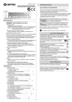
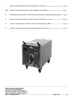
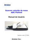
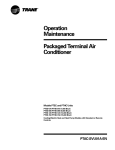
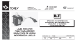
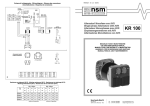
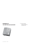
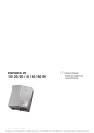
7MAN012 rel. 1.3.0 03/09 Schema di collegamento - Wiring diagram - Schema des connexions Anschlubschema - Esquema de conexiones power switch range selector 2 Gamme di Saldatura 2 Welding Ranges 50Hz 1 phase WS WS WS WS Welding Bridge (optional) Battery charger DC DC TDC DC Rotor Saldatrici DC/TDC DC/TDC Welding machines Soudeses DC/TDC DC/TDC Schweissmaschinen Soldadoras DC/TDC yellow 60Hz 1 phase Power switch Range Selector grey white red black black black red Generator black black power switch black red brown WS TDC MANUALE D'USO E MANUTENZIONE USE AND MAINTENANCE MANUAL MANUEL POUR L'ENTRETIEN ET LA MANUTENTION HANDBUCH FÜR DIE BEDIENUNG UND WARTUNG MANUAL PARA EL USO Y MANTENIMIENTO black blue brown red white blue WS DC 12Vdc - 10A 24 / 12Vdc - 10A red red # green (white) blue 8 brown black Impedance black black (by-pass) blue yellow1 Generator grey (brown) Welding winding blue black brown Auxiliary 180 220 220 200 range selector 3 Gamme di Saldatura 3 Welding Ranges WS 240 DC WS 240 TDC Welding Bridge (optional) Battery charger Auxiliary 50/60Hz 3 phase Rotor white red yellow green white blue 8 blue white black brown Generator white white black blue brown white grey grey (brown) Impedance black (by-pass) yellow1 Welding winding 12Vdc - 10A 24 / 12Vdc - 10A red Range Selector Power switch black black red black white red black Fig. 2 black nero white bianco blue blu brown marrone grey grigio red rosso yellow giallo noire schwartz blanc weiss bleu blau marron braun gris grau rouge rot jaune gelb negro blanco azul marron gris rojo amarillo # WS180/200/220 DC: green WS220 TDC: white Nuova Saccardo Motori Srl Via Lazio, 5 36015 Schio (Vicenza) - Italy tel: +39 0445 595888 fax: +39 0445 595800 www.nsmgenerators.com [email protected] ISTRUZIONI D'USO INSTRUCTIONS MODE D' EMPLOI BEDIENUNGSANLEITUNG Lo scopo delle presenti istruzioni é indicare agli Object of these instructions is to give the user correct L`objet des ces instructions est d`indiquer aux Ziel der vorliegenden Anweisungen ist es, den utilizzatori le corrette condizioni d`impiego delle operating-conditions about NSM welders. utilisateurs les correctes conditions d`emploi B e n u t z e r n d i e o r d n u n g s g e m ä ß e n Technical data not binding: NSM reserves the right to modify concernant NSM soudeses. Einsatzbedingungen der NSM - Schweissmaschinen saldatrici NSM. Données techniques non contraignantes: NSM se réserve le darzulegen. Dati tecnici non impegnativi: NSM si riserva il diritto di the contents without prior notice droit d’en modifier le contenu sans obligation de communication préalable apportare modifiche senza l’obbligo di darne preventiva comunicazione Unverbindliche technische daten: NSM behält sich das Recht vor, ohne Ankündigung, am Inhalt Veränderungen vorzunehmen INSTRUCCIONES DE USO El objeto de las presentes instrucciones es indicar a los usuarios las correctas condiciones de empleo de los soldadoras NSM. Datos tecnicos sin compromiso: NSM se reserva el derecho de aportar modificaciones sin la obligación de previo aviso ATTENZIONE! WARNING! ATTENTION! ACHTUNG! ATTENCIONES! Le istruzioni fornite riportano informazioni atte ad essere utilizzate da personale tecnico qualificato; esse devono essere integrate dalle leggi e dalle norme vigenti. Le macchine elettriche rotanti presentano parti pericolose in quanto poste sotto tensione ed in rotazione. Pertanto un uso improprio, la carenza di manutenzione e lo scollegamento dei dispositivi di protezione possono essere causa di gravi danni a persone o cose. The operating instructions include only the directions to be followed by the qualified personnel; they must be supplemented by the relevant legal provisions and standards. Electric rotating machines have dangerous parts: they have live and rotating components. Therefore: improper use, inadequate inspection and maintenance and the removal of protective covers and the disconnection of protection devices can cause severe personal injury or property damage. Les instructions fournies contiennent des informations destinèes au personnel qualifiè; elles doivent etre completèes par le dispositions de loi ou par les normes techniques en viguer. Les machines electriques rotatives sont des machines prèsentant des parties dangereuses car elles sont sous tension ou en mouvement. Par consèquent: une utilisation anormale, la non inspection et le dèbranchement des dispositifs de protection peuvent entrainer de graves dommages pour les personnes ou les choses. Die Anweisungen dieses Informationsblattes richten sich daher an qualifiziertes Fachpersonal; die Anweisungen ergänzen die gesetzlichen Vorschriften und die geltenden technischen Normen und ersetzen keine Anlagennorm. Elektrische Rotationsmaschinen weisen gefährliche Teile auf, die entweder unter Spannung stehen oder sich während des Maschinenbetriebes drehen. Daher können: unsachgemäBer Gebrauch, Entfernen der Schutzverkleidungen und Überbrücken oder Abklemmen der Schutzeinrichtungen, mangelhafte Inspektion oder Wartung zu schweren Schäden an Personen oder Sachen führen. Las presentes instrucciones dan informaciones adecuadas para el personal cualificado; dichas informacciones tienen que complementarse con las leyes y normas tècnicas vigentes. Las màquinas elèctricas giratorias son màquinas que presentan piezas peligrosas ya que estàn bajo tensiòn o se mueven durante el funcionamiento. Por lo tanto: si se hace un uso indebido, si no se efectùan los controles y mantenimientos indicados, si se quitan las protecciones y se desconectan los dispositivos de seguridad se pueden provocar daños graves a personas o cosas. VERIFICHE PRELIMINARI Al momento della ricezione si raccomanda di esaminare la saldatrice per controllare che non abbia subito danni durante il trasporto. PRELIMINARY CHECKS On receipt it is recommended to inspect the welder to find out whether it has got damages during transportation. VERIFICATION PRELIMINAIRES Aprés la réception on récommande d`examiner la soudese afin de vérifier qu`il n`a pas été endommagé pendant le transport. VORABÜBERPRÜFUNGEN Es wird empfohlen, den Schweissmaschine unmittelbar nach Erhalt zu überprüfen um sicherzustellen, daß während des Transports keine Schäden entstanden sind. VERIFICACIONES PRELIMINARES En el momento de la recepción se recomienda examinar la soldadora para comprobar que no haya sufrido daños durante el transporte. IMMAGAZZINAGGIO Se la saldatrice non viene posta immediatamente in servizio dovrà essere immagazzinato in luogo coperto, pulito, e privo d`umidità. Prima della messa in servizio dopo lunghi periodi di inattività é consigliabile verificare la resistenza di isolamento di tutti gli avvolgimenti. Con macchina a temperatura ambiente si devono misurare valori maggiori di 2 MW. In caso contrario bisogna procedere all`essicazione in forno (a circa 60º-80ºC). STORAGE If the welder is not installed immediately, it should be kept indoor, in a clean and dry place. Before starting up the alternator after long periods of inactivity or storage, the windings insulation resistance must to be measured. That should be higher than 2 MW at room temperature. If this value cannot be obtained it is necessary to reset the insulation, drying the windings (using an oven at 60º-80º C). STOCKAGE Au cas où la soudese ne doit pas être mis en service immédiatament, il faut le stocker dans un endroit couvert, propre et sec. Aprés de longues périodes d`inactivité ou de stockage, on conseille de measurer la résistance d`isolation de enroulement qui devra être au dessue de 2 MW . Si l`on ne peut pas obtenir cette valeur il est nécessaire de remettre l`isolation en état, en séchant l`enroulement (utilisant un four a 60º-80º C). LAGERUNG Falls der Schweissmaschine nicht sofort in Betrieb genommen werden soll, ist er an einem überdachten, sauberen und trocken Ort einzulagern. Falls eine Inbetriebnahme nach einer langen Standzeit erfolgen soll ist es ratsam, den Isolationswiderstand aller Wicklungen zu überprüfen. Bei Maschine auf Raumtemperatur müssen Werte von über 2 MW gemessen werden. Im gegenteiligen Fall muß eine Trocknung im Ofen erfolgen (bei ca. 60° - 80° C). ALMACENAJE Si la soldadora no va a ser puesto inmediatamente en servicio, deberá ser almacenado en un lugar cubierto, limpio y exento de humedad. Antes de la puesta en marcha después de largos períodos de inactividad es aconsejable verificar la resistencia de aislamiento de todos los bobinados. Con la máquina a temperatura ambiente se deben obtener valores superiores a 2 MW. En caso contrario es necesario proceder al secado en horno (60º-80ºC aprox.). ACCOPPIAMENTO MECCANICO Si vedano le istruzioni per il montaggio. MECHANICAL COUPLING See assembling instructions. ACCOUPLEMENT MECANIQUE Voyez l`operation de montage. MECHANISCHE KOPPLUNG siehe Montageanleitung. ACOPLAMIENTO MECANICO Véanse las instrucciones para el montaje. COLLEGAMENTO ELETTRICO Verificare che le varie apparecchiature da collegare al generatore/saldatrice siano conformi ai dati di targa. Eseguire i collegamenti come da schema di fig.2, provvedendo anche alla messa a terra della saldatrice, utilizzando i morsetti predisposti allo scopo. Prima di destinare la saldatrice all'uso è necessario controllare che quanto sopra riportato sia stato eseguito correttamente, verificando inoltre che non vi siano impedimenti alla rotazione del rotore, e controllando che nel funzionamento a vuoto le tensioni presenti su ogni presa del quadro elettrico corrispondano a quanto previsto. Attenzione!: E' pericoloso il funzionamento a carico ad un n° giri diverso dal valore nominale (scostamento max: -2%,+5%): questo tipo di servizio rappresenta una condizione di sovraccarico. ELECTRIC CONNECTION Make sure that the various equipment to be connected to the generator/welder conforms to the rating plate data. Carry out the connections as shown in the diagram of fig. 2 and earth the welder by means of the terminals supplied for this purpose. Before using the welder, it is necessary to make sure that the above-mentioned procedures have been carried out correctly and that no obstacles to rotor rotation are present. Also check that when the welder runs in no load condition the current measured on each outlet on the electric board corresponds to the recommended rated voltage. Warning!: it is dangerous to operate the welder with a load at a RPM different than the nominal value (max deviation: -2%,+5%): this type of working represents an overload condition. CONNEXION ELECTRIQUE Assurez-vous que les différents appareillages à connecter au générateur/à la soudeuse sont conformes aux données indiquées sur la plaque signalétique. Effectuer les branchements au moyen des borniers prévus comme indiqué sur la figure 2, réalisant également la mise à la terre de la soudese. Avant d'utiliser la soudese, il est nécessaire de vérifier que les points ci-dessus aient été effectués, que rien n'empêche le mouvement du rotor et que les tensions prévues pour chaque prise du tableau électrique soient présente lors du fonctionnement à vide. Attention!: Il est dangereux de faire fonctionner à charge à n° tours différent à la valeur nominale (écart max.: -2%, +5%): ce type de fonctionemment représente une condition de surcharge. ELEKTRISCHER ANSCHLUß Vergewissern Sie sich, dass die einzelnen, an den Generator/das Schweißgerät anzuschließenden Geräte den Daten auf dem Typenschild entsprechen. Die Anschlüsse nach dem Schema in Abb. 2 vornehmen und dabei auch den Schweißmaschine mit den vorgesehenen Klemmen erden. Vor dem Gebrauch des Schweißmaschine muß geprüft werden, ob der oben beschriebene Schritt richtig ausgeführt wurde. Außerdem ist zu kontrollieren, ob der Rotor in seiner Drehung behindert wird und ob im lastfreien Betrieb die anliegenden Spannungen an den einzelnen Buchsen des Schaltkastens den vorgeschriebenen Werten entsprechen. Acthung!: Beim Betrieb unter Last sollte in jedem Fall eine Drehzahl unterschiedlich als der Nennwert (max. Abweichung: -2%, +5%) vermieden werden, denn diese Betriebsart stellt eine Überlastung. CONEXION ELECTRICA Comprobar que los varios equipos que deben empalmarse al generador/soldadora cumplan las características indicadas en la plaquita de datos nominales. Realizar las conexiones de la figura 2, procediendo también a la puesta a tierra de la soldadora, utilizando los bornes que se han preparado para esta finalidad. Antes de destinar la soldadora a la utilización resulta necesario controlar que lo que se ha indicado antes se haya realizado correctamente, controlando además que no existan impedimentos para la rotación del rotor, y controlando que durante el funcionamiento en vacío las tensiones eléctricas presentes en cada toma de corriente del cuadro eléctrico correspondan a lo que se ha previsto. Advertencia!: es peligroso el funcionamiento con carga a un n° de vueltas diferente al valor nominal (desviacion max: -2%, +5%): este tipo de funcionamiento representa una situación de sobrecarga. INSTALLAZIONE Installare il gruppo in un locale ben ventilato. Fare attenzione che le aperture di aspirazione ed espulsione dell`aria di raffreddamento siano libere. La saldatrice deve aspirare aria pulita: è importante evitare l'aspirazione dell'aria calda espulsa dalla saldatrice stessa e/o dal motore primo, nonché i gas di scarico del motore, polveri e sporcizia varia. INSTALLATION Set up the unit in a well-cooled place. Make sure that cooling air intake and discharge openings are free and unblocked. The welder must suck in clean air only: the suction of the hot air expelled from the welder itself and/or the prime motor must be avoided, as well as the suction of motor exhaust fumes, dust and dirt. INSTALLATION Le groupe doit être installé dans un endroit bien ventilé. S`assurer que les ouvertures de ventilation ne sont pas obstruées. La soudese doit aspirer de l'air propre: il est important d'éviter l'aspiration de l'air chaud expulsé par la soudese lui-même et/ou par le moteur primaire, ainsi que les gaz d'échappement de ce moteur, les poussières et les impuretés diverses. ANBRINGUNG Das Aggregat in einem gut gelüfteten Raum installieren. Es ist darauf zu achten, daß die Öffnungen für Einlaß und Auslaß der Kühlungsluft frei sind. Der Schweißmaschine muss saubere Luft ansaugen. Es ist wichtig, dass vermieden wird, dass die warme, vom Schweissmaschine selbst bzw. vom ersten Motor ausgestoßene Luft sowie Abgase des Motors, Staub und verschiedener Schmutz angesaugt werden. INSTALACION Instalar el grupo en un local bien ventilado. Asegurarse de que las ventanas de aspiración y expulsión del aire de refrigeración estén libres. La soldadora tiene que aspirar aire limpio: es importante evitar la aspiración del aire caliente expulsado por la soldadora y/o por el motor primario, así como los gases de escape del motor, polvo y suciedad en general. MANUTENZIONE La saldatrice e gli eventuali accessori devono essere sempre tenuti puliti. Verificare periodicamente che il gruppo funzioni senza vibrazioni o rumori anomali e che il circuito di ventilazione non sia ostruito. Ve r i f i c a r e p e r i o d i c a m e n t e l ` u s u r a e d i l posizionamento delle spazzole MAINTENANCE The welder as well as the possible accessories should always be kept clean. It is recommended to periodically check that the unit operates without anomalous vibrations or noises, and the ventilation circuit is not obstructed. Periodically check the wear and the position of the brushes. ENTRETIEN La soudese et les éventuels accessoires doivent être toujourus propres. Vérifier périodiquement que le groupe fonctionne sans vibrations ou bruits anomaux, et que le circuit de ventilation ne soit pas obstruée. Contrôler avec périodicité la position et l`usure des balais WARTUNG Der Schweissmaschine und eventuelle Zubehörteile müssen immer sauber gehalten werden. Regelmäßig überprüfen, daß das Aggregat frei von Vibrationen und ungewöhnlichen Geräuschen funktioniert und der Belüftungskreislauf nicht verstopft ist. Bei Bürstengeneratoren ist regelmäßig der Verschleiß und die Positionierung der Bürsten zu überprüfen MANTENIMIENTO La soldadora y los posibles accesorios deben mantenerse siempre limpios. Verificar periódicamente que el grupo funciona sin vibraciones ó ruidos anormales y que el circuito de ventilación no esté obstruído. Verificar periodicamente el desgaste y el posicionado de las escobillas ISTRUZIONI PER IL MONTAGGIO ASSEMBLING INSTRUCTIONS INSTRUCTIONS DE MONTAGE MONTAGEANLEITUNG FORMA MONOSUPPORTO SINGLE-BEARING FORM FORME MONOPALIER FORM EINZELAUFHÄNGUNG ATTENTION: Avant le montage verifier que les siéges coniques pour l`accouplement (de la soudese et du moteur) soient en ordre et propres. ATTENZIONE: prima del montaggio verificare che le sedi coniche di accoppiamento (sia della saldatrice che del motore) siano regolari e ben pulite. CAUTION: before assembling verify that the conical coupling parts (both motor and welder) are in order and clean. FORMA B3/B9: 1) Fissare lo scudo S al motore utilizzando viti e rosette adeguate allo scopo (fig.1A). B3/B9 FORM: 1) Fasten the shield S to the motor using screws and washers adequate to the purpose. (fig.1A). FORME B3/B9: 1) Fixez la flasque S au moteur à l'aide de vis et de rondelles appropriées.(fig.1A). 2) Applicare il tirante T per il fissaggio assiale del rotore avvitandolo a fondo sulla sporgenza dell'albero motore (fig.1A). 2) Apply the rod T for the axial clamping of the rotor, and screw it tight on the engine shaft.(fig.1A). 2) Monter la tige centrale T pour la fixation axiale, la vissant a fond sur le bout d`arbre du moteur (fig.1A). SAE FORM: 1a) Fix the G1 joint to the motor flywheel with suitable screws (min. resistance class 8.8) and washers (fig.1E). FORME SAE: 1a) Fixer le joint G1 au volant du moteur en utilisant des vis (classe min. de résistance 8.8) et des rondelles appropriées (fig.1E). 1b) Fix the F1 flange to the motor flywheel cover using suitable screws and washers (fig.1F). 1b) Fixer la bride F1 au couvre-volant du moteur en utilisant des vis et des rondelles appropriées (fig.1F). FORMA SAE: 1a) Fissare il giunto G1 al volano del motore utilizzando viti (classe min. di resistenza 8.8) e rosette adeguate allo scopo (fig.1E). 1b) Fissare la flangia F1 alla campana coprivolano del motore utilizzando viti e rosette adeguate allo scopo (fig.1F). 2a) Fissare lo scudo S alla flangia F1 utilizzando le viti V e le rosette R in dotazione (coppia di serraggio 25Nm) ( fig.1F). 2b) Applicare il tirante T per il fi ssaggio assiale del rotore avvitandolo a fondo sulla sporgenza del giunto (fig.1F). 2a) Fasten the S shield to the F1 flange using the supplied V screws and R washers (driving torque 25Nm) ( fig.1F). 2b) Apply the tie-rod T to axially secure the rotor and fully tighten onto the projecting part of the joint (fig.1F). 2a) Fixer le flasque S à la bride F1 en utilisant les vis V et les rondelles R fournies (couple de serrage 25Nm) ( fig.1F). 2b) Appliquer la tige centrale T pour la fixation axiale du rotor en la vissant à fond sur la partie saillante du joint (fig.1F). ACHTUNG: Vor der Montage ist zu überprüfen, dass die Kegelsitze gleichmäßig und sauber sind. INSTRUCCIONES PARA EL MONTAJE FORMA MONOSOPORTE ATENCION: Antes del montaje, verificar que las partes cónicas del acoplamiento estén en orden y bien limpias. FORM B3/B9: 1) Den Lagerschild S mit Hilfe entsprechenden Schrauben und Unterlegscheiben am Motor befestigen. (Abb.1A). FORMA B3/B9: 1) Fijar la caja S al motor utilizando los tornillos y arandelas adecuados para ello. (fig.1A) 2) Die Zugstange T für die Achsbefestigung des Rotors durch vollständiges Einschrauben auf dem Überstand der Motorwelle anbringen (Abb.1A). 2) Montar el tirante T para la fijación axial del rotor atornillándolo a fondo sobre el saliente del cigüeñal del motor (fig.1A) FORM SAE: 1a) Die Kupplung G1 mit geeigneten Schrauben (Mindestbeständigkeitsk lasse 8.8) und Unterlegscheiben am Motorschwungrad festmachen (Abb.1E). FORMA SAE: 1a) Fijar la junta G1 al volante del motor utilizando tornillos (clase mín. de resistencia 8.8) y arandelas adecuados para ello (fig.1E). 1b) Den Flansch F1 an der Schutzglocke des Motorschwungrads festmachen. Hierzu geeignete Schrauben und Unterlegscheiben verwenden (Abb.1F). 2a) Den Lagerschild S mit Hilfe der mitgelieferten Schrauben V und Unterlegscheiben R am Flansch F1 befestigen (Anzugsmoment 25Nm) (Abb.1F). 2b) Die Zugstange T zur Axialfeststellung des Rotors anbringen und energisch auf dem Kupplungsvorsprung aufschrauben (Abb. 1F) 1b) Fijar la brida F1 a la campana cubrevolante del motor utilizando tornillos y arandelas adecuados para ello (fig.1F). 2a) Fijar el escudo S a la brida F1 utilizando los tornillos V y las arandelas R incluidos en el suministro (par de apriete 25Nm) (fig.1F). 2b) Instalar el tirante T para la fijación axial del rotor, enroscándolo completamente en el resalto de la junta (fig.1F). B3/B9 S fig.1A F1 R7 V7 fig.1E R V6 V fig.1F S R V T T SAE G1 3) Fissare la saldatrice completa allo scudo con le 4 viti V1 e relative rosette R1 in dotazione (coppia di serraggio 25Nm) (fig.1B). 3) Fasten the complete welder to the shield using the 4 screws V1 and washers R1 provided (driving torque 25Nm). (fig.1B). 4) Bloccare assialmente il rotore applicando le rosette R2 e serrando il dado autobloccante D2 sul tirante T con chiave dinamometrica (coppia di serraggio 25÷30Nm) (fig.1B). 4) Lock axially the rotor by placing the washers R2 and tight the self-locking nut D2 on the rod T, using a torque spanner (driving torque 25÷30Nm). (fig.1B). Attenzione: prima di applicare il dado osservare che la porzione filettata del tirante penetri nel rotore permettendo cosìun sicuro bloccaggio. Caution: before applying the nut, make sure that the threaded part of the rod enters the rotor, in order to obtain a tight lock. 5) Ruotare il portaspazzole PS fino a posizionarlo nella propria sede, in modo che le spazzole facciano contatto sul collettore ad anelli, e fissarlo avvitando la vite V5 Verificare sempre che il posizionamento delle spazzole sia ben centrato sugli anelli del collettore 6) Collegare i connettori C e C1; effettuare la messa a terra e l'eventuale collegamento del carica batterie (vedi schema elettrico Fig.2); bloccare il gruppo connettori alla carcassa, mediante innesto nella apposita sede predisposta C2 5) Rotate the PS brush-holder until it fits into its housing in such way that the brushes make contact with the slip ring, and then fasten it in place using the V5 screw Always check to make sure that the brushes are suitably centred on the slip rings 6) Join the C and C1 connectors; after making the ground connection and the connection to the battery-charger (see wiring diagram Fig.2); fasten the connector unit to the frame by fitting it into the C2 housing provided 3) Fixez la soudese complet à la flasque à l'aide des 4 vis V1 et des rondelles correspondantes R1 fournies en dotation (couple de serrage 25Nm). (fig.1B) 3) Den kompletten Schweissmaschine mit Hilfe von 4 Schrauben V1 und entsprechenden Unterlegscheiben R1 am Lagerschild befestigen (Anzugsmoment 25Nm) (Abb.1B). 4) Bloquer axialement le rotor, en utilisant les rondelles R2 et vissant a fond l`écrou autobloquant D2 sur la tige centrale T en utilisant la clef dynamometrique (couple de serrage de 25÷30Nm) (fig.1B). 4) Den Rotor in Achsenrichtung blockieren, indem man die Unterlegscheiben R2 anbringt und die selbstsperrende Mutter D2 auf der Zugstange T mit einem Drehmomentenschlüssel anzieht (Drehmoment 25÷30Nm). (Abb.1B) Attention: avant de mettre l`écrou, controler que la partie fileteé de la tige centrale entre dans le rotor, permettant ainsi un bloquage fermé. Achtung: Bevor die Mutter angebracht wird, ist sicherzustellen, dass der Gewindeteil der Zugstange in den Rotor eingeschraubt wird, um eine sichere Blockierung zu ermöglichen. 5) Tournez le porte-brosses PS jusqu'à ce qu'il soit mis en place, et de telle manière que les brosses soient au contact du collecteur à bagues. Puis fixezle en vissant la vis V5 Assurez-vous toujours que le positionnement des brosses est bien centré sur les anneaux du collecteur 6) Connectez les connecteurs C et C1. Mettez à la terre et connectez éventuellement le chargeur de batteries (voir le schéma électrique Fig.2). Solidarisez le groupe de connecteurs à la carcasse par emboîtement dans le siège C2 prévu à cet effet 5) Den Bürstenhalter PS bis zum Einrasten in der Aufnahme drehen, so dass die Bürsten mit dem Schleifring in Berührung kommen, und diesen durch Anziehen der Schraube V5 befestigen. Stets überprüfen, dass die Bürsten mittig an den Ringen des Schleifrings ausgerichtet sind 6) Der Verbinder C und C1 an der Schalttafel anschließen. Die Erdung und ggf. den Anschluss des Batterieladegeräts ausführen (siehe Schaltplan Fig.2); den Verbindersatz durch Einrasten der entsprechenden, vorbereiteten Aufnahme C2 am Gehäuse blockieren 3) Fijar la soldadora completa a la caja con los 4 tornillos V1 y correspondientes arandelas R1 incluidas (par de torsión 25Nm). 4) Bloquear axialmente el rotor utilizando las arandelas R2 y apretando la tuerca autoblocante D2 sobre el tirante T con llave dinamométrica (par de apriete 25÷30Nm) (fig.1B). Atención : antes de montar la tuerca asegurarse de que la parte roscada del tirante entra en el rotor, permitiendo así un blocaje seguro. 5) Girar el portaescobillas PS hasta que entre en su alojamiento, de manera que las escobillas estén en contacto con el colector de anillos, y fijarlo apretando el tornillo V5 Comprobar siempre que la posición de las escobillas esté bien centrada en los anillos del colector 6) Conectar los conectores C y C1; efectuar la toma de tierra y la eventual conexión del cargador de baterías (véase esquema eléctrico Fig.2); fijar el grupo conectores a la carcasa, acoplándolo en el específico alojamiento predispuesto C2 ISTRUZIONI PER IL MONTAGGIO ASSEMBLING INSTRUCTIONS OPERATION DE MONTAGE MONTAGEANLEITUNG FORMA MONOSUPPORTO SINGLE-BEARING FORM FORME MONOPALIER FORM EINZELAUFHÄNGUNG 7) Fasten the P4 electric control panel to the welder using the 6 V4 screws (self-tapping M5×16 screws) provided (or 4 screws for the protection casing without sockets) 7) Solidarisez le tableau électrique P4 et la soudese à l'aide des 6 vis V4 (vis autotaraudeuses M5×16) fournies en dotation (4 vis si le protecteur n'a pas de prise) 8) close the hole on the electric control panel using the P5 plastic plug; close the holes on the rear side of the frame (if not used) using the P1 membranetype cable glands 8) fermez le trou qui se trouve sur le tableau électrique à l'aide du bouchon en plastique P5. Fermez les trous qui se trouvent à l'arrière de la carcasse (s'ils ne sont pas utilisés) à l'aide des passe-câbles à membrane P1 7) Die Schalttafel P4 mit Hilfe der 6 im Lieferumfang enthaltenen, (selbsteinschneidenden M5×16) Schrauben V4 (4 Schrauben im Falle der Abdeckplatte ohne Steckdosen) am Schweissmaschine befestigen 7) Fissare il quadro elettrico P4 alla saldatrice, utilizzando le 6 viti V4 (automaschianti M5×16) in dotazione (4 viti nel caso di cuffia senza prese) 8) chiudere il foro presente sul quadro elettrico con il tappo in plastica P5, e quelli sul lato posteriore della carcassa (se non utilizzati) mediante i passacavi a membrana P1 9) posizionare il coperchio P3 e fissarlo serrando le viti flangiate V3 10) montare le due protezioni IP23 P2, fissandole ai fianchi dello scudo anteriore con le apposite viti V2 (automaschianti M5×16) nei 3 punti previsti 11) fissare la saldatrice al telaio utilizzando supporti antivibranti adeguati 9) position the cover P3 and fasten it in place using the flanged V3 screws 10) assemble the two P2 IP23 protections and fasten them to the sides of the front shield using the respective V2 screws (self-tapping M5×16 screws) in the 3 points foreseen 11) fasten the welder to the frame using appropriate vibration-damping supports 9) positionnez ce couvercle P3 puis fixez-le en vissant les vis à bride V3 10) montez les deux dispositifs de protection IP23 P2, en les fixant aux 3 points prévus sur les côtés de la flasque avant à l'aide des vis V2 (autotaraudeuses M5×16) prévues à cet effet 11) fixez la soudese au cadre au moyen des supports antivibrants adéquate 8) die an der Schalttafel vorhandene Bohrung mit dem Kunststoffstopfen P5 und die Bohrungen auf der Rückseite des Gehäuses (sofern sie nicht genutzt werden) mit Hilfe von Kabeldurchführungen mit Membrane P1 verschließen 9) den Deckel P3 platzieren und ihn mit Hilfe der Flanschschrauben V3 durch Anziehen befestigen 10) die beiden Schutzeinrichtungen IP23 P2 durch Befestigen mit den entsprechenden, (selbsteinschneidenden M5×16) Schrauben V2 an den Seiten des vorderen Lagerschilds an den 3 vorgesehenen Stellen einbauen INSTRUCCIONES PARA EL MONTAJE FORMA MONOSOPORTE 7) Fijar el cuadro eléctrico P4 a la soldadora, utilizando los 6 tornillos V4 (de rosca cortante M5×16) incluidos en el suministro (4 tornillos si el resguardo no tiene tomas) 8) cerrar el agujero que hay en el cuadro eléctrico con el tapón de plástico P5, y los que hay en el lado trasero de la carcasa (si no se utilizan) mediante los aisladores pasapanel de membrana P1 9) colocar la tapa P3 y fijarla apretando los tornillos con bridas V3 10) montar las dos protecciones IP23 P2, fijándolas a los lados de la caja delantera con los específicos tornillos V2 (de rosca cortante M5×16) en los 3 puntos previstos 11) fijar la soldadora al bastidor utilizando soportes antivibrantes adecuados 11) den Schweissmaschine mit Hilfe von Schwingmetallen am Rahmen befestigen Fig. 1C Fig. 1B Fig. 1D P3 PS P4 P1 V5 V4 C1 T R2 D2 Innestare e ruotare plug in and rotate V2 P2 R1 V1 V3 P1 C2 C P5 ISTRUZIONI PER IL MONTAGGIO ASSEMBLING INSTRUCTIONS INSTRUCTIONS DE MONTAGE MONTAGEANLEITUNG FORMA B34 (bi-supporto) B34 FORM (double bearing) FORME B34 (bi-palier) FORM B34 (doppeltes Lager) FORMA B34 (bi-soporte) si raccomanda di realizzare l'allineamento con cura, verificando che lo scarto di concentricità e parallelismo dei due semi-giunti non sia superiore a 0.1mm. the alignment must be made with care, checking that the difference in concentricity and parallelism of the two half joints does not exceed 0.1mm il est conseillé d'effectuer l'alignement avec soin, en vérifiant que l'écart de concentricité et de parallélisme des deux semi-joints ne résulte pas supérieur à 0.1mm. Die Ausrichtung ist besonders sorgfältig durchzuführen. Entsprechend ist zu überprüfen, dass die Abweichung von der Konzentrizität und der Parallelität nicht mehr als 0,1mm beträgt. se recomienda efectuar la alineación con cuidado, verificar que el error de concentricidad y paralelismo de los dos semi-acoplamientos no sea superior a 0,1mm - Appliquez sur la soudese le demi-joint de couplage et la cloche d'alignement - Die Kupplungshälfte und die Kupplungsglocke am Schweissmaschine anbringen - Aplicar a la soldadora la semijunta de acoplamiento y la campana de alineación - Appliquez à l'arbre du moteur l'autre demi-joint de couplage - Die andere Kupplungshälfte an der Motorwelle anbringen - Aplicar la otra semijunta de acoplamiento al eje del motor - Couplez la soudese et le moteur, en fixant la cloche d'alignement - Schweissmaschine und Motor durch Befestigen der Kupplungsglocke - Acoplar soldadora y motor, fijando la campana de alineación Assurez-vous qu'il existe un espace suffisant pour le palier postérieur afin de permettre la dilatation axiale du rotor (au moins 1 mm) Sicherstellen, dass für das hintere Lager ausreichend Platz vorhanden ist, um eine axiale Ausdehnung des Läufers zu gestatten (mindestens 1mm) Comprobar que para el cojinete trasero exista un espacio suficiente que permita la dilatación axial del rotor (como mínimo 1 mm) - Applicare alla saldatrice il semigiunto di accoppiamento e la campana di allineamento - Applicare all'albero del motore l'altro semigiunto di accoppiamento - Accoppiare saldatrice e motore, fissando la campana di allineamento Verificare che per il cuscinetto posteriore esista uno spazio sufficiente a permettere la dilatazione assiale del rotore (almeno 1mm) da questo momento procedere come indicato al punto 5 e seguenti delle istruzioni per il montaggio della forma monosupporto - Apply the half-coupling and the adapter to the welder - Apply the other half-coupling to the motor shaft - Couple the welder and the motor and fasten the adapter Make sure there is enough space for the rear bearing to permit the axial expansion of the rotor (at least 1mm) from now on proceed as indicated at step 5 of the instructions for mounting the single-bearing form Procéder ensuite comme indiqué au point 5 et suivants des instructions de montage de la forme monopalier Ab diesem Punkt ist die Vorgehensweise gleich wie jene beginnend mit Punkt 5 der Montageanweisungen für die Form Einzelaufhängung INSTRUCCIONES PARA EL MONTAJE De este momento en adelante seguir las indicaciones del punto 5 y siguientes de las instrucciones para el montaje de la forma monosoporte funzionamento come SALDATRICE : Betrieb als SCHWEIßMASCHINE a) disporre il Power Switch sulla gamma di saldatura desiderata b) impostare il valore di corrente di saldatura Is mediante il Range Selector a) Den Power Switch auf den gewünschten Schweißbereich stellen b) Einstellung des Is Schweißstromes mittels des Range Selector o saldatura con elettrodi acidi/rutili: connettere il cavo porta-elettrodo al morsetto negativo – o saldatura con elettrodi basici/cellulosici: connettere il cavo porta-elettrodo al morsetto positivo + o Schweißen mit Acid/Rutil-Elektroden: Verbindung des Elektrodenhalterkabels mit dem negativen endverschlüß – o Schweißen mit Basisch/Zellstoffartig-Elektroden: Verbindung des Elektrodenhalterkabels mit dem positiven endverschlüß + funzionamento come GENERATORE : Betrieb als GENERATOR a) disporre il Power Switch in posizione GEN (il Range Selector può trovarsi in qualsiasi posizione) a) Den Power Switch in die Stellung GEN stellen (der Range Selector kann sich in jeder beliebigen Stellung befinden) AVVERTENZE : - si consiglia di non utilizzare contemporaneamente la macchina come saldatrice e generatore (la tensione ottenibile non sarebbe costante) - serrare accuratamente i cavi di uscita alle boccole per evitare problemi di surriscaldamento dovuti a contatti incerti WARTUNG : - Beachten Sie, daß es nicht raten ist, gleichzeitig zu Schweißen und die Generator-funktion zu nutzen (Die erzielbare Spannung wäre nicht konstant) - Um Überhitzungen durch schlechte Kontakte zu vermeiden, sind die Verbindungen der An schlußkabel sorgfältig vorzunehmen La saldatrice é fornita di protezione termica autoripristinabile contro forti sovraccarichi. Die Schweissmaschine ist mit einem Überlastungsschutz geliefert. functionning as WELDING MACHINE funcionamiento como SOLDADORA: a) place the Power Switch on the desired welding range b) set up the value of Is welding current through the Range Selector a) disponer el Power Switch en el campo de soldadura deseado b) Introducir el valor de la corriente de soldadura Is a través del Range Selector o welding with acid/rutil electrodes : connect the electrode-stand wire to the negative terminal – o welding with basic/cellulosic electrodes : connect the electrode-stand wire to the positive terminal + o Soldadura con electrodos ácidos/de rutilo : conectar el cable porta-electrodo a el terminal negativo – o Soldadura con electrodos basicos/celulosicos : conectar el cable porta-electrodo a el terminal positivo + functionning as GENERATOR funcionamiento como GENERADOR: a) place the Power Switch in GEN position (the Range Selector can be in any position) a) disponer el Power Switch en posición GEN (el Range Selector puede estar en cualquier otra posición) DIRECTIONS : - we suggest to not utilize the machine as welding machine and generator at the same time (the output voltage wouldn’t be stable) - to avoid overheat problems due to faulty contacts we suggest to close the outlet wires to terminals carefully AVERTENCIAS : - se aconseja que no utilizar simultáneamente la máquina como soldadora y como generador (la tensión obtenible no sería constante) - apretar cuidadosamente los cables de salida de los terminales para evitar prolemas de sobrecalentamiento debidos a contactos dudosos The welder is supplied with thermal breaker (autoresettable) against high overloads. La soldadora la suministramos con un dispositivo termico que se restablece automaticamente. fonctionnement comme APPAREIL DE SOUDAGE a) positionner le Power Switch sur la gamme de soudage désirée b) placer le valeur de courant de soudage Is par le Range Selector o soudage avec électrodes acides/rutiles : connecter le câble porte-electrode á la borne négative – Power Switch o soudage avec électrodes basiques/cellulosiques : connecter le câble porte-electrode á la borne positive + fonctionnement comme GENERATEUR a) placez le Power Switch en position GEN (le Range Selector peut se trouver dans n’importe quelle position) INSTRUCTIONS : - on conseille de n' utiliser pas la machine comme appareil de soudage et générateur en même temps (la tension que l’on pourrait obtenir ne serait pas constante) - fermer bien les câbles de sortie á les bornes pour éviter des problémes de surchauffe dues á mauvais contacts La machine est protegée avec un dispositive thermique (avec retablisement) contre élevé surcharges. + terminal - terminal Range Selector RICERCA GUASTI DIFETTO CAUSA - RIMEDIO Manca tensione in uscita a vuoto alla partenza - Macchina smagnetizzata: a macchina avviata applicare ai morsetti + e – del ponte diodi (rotore) per un secondo una tensione continua compresa tra i 4.5 e 12V - Ponte diodi difettoso: sostituirlo - Avvolgimento in cto o difetto di isolamento o connessioni difettose. Controllare le resistenze degli avvolgimenti (vedi tabella) e l`isolamento Tensione bassa a vuoto Corrente di saldatura bassa - Power switch in posizione errata: disporlo su GEN - Velocitá del motore troppo bassa: regolare la velocitá a 3150rpm (50Hz) o 3750rpm (60Hz) a vuoto. - Ponte diodi difettoso: sostituirlo - Avvolgimenti in cortocircuito: controllare le resistenze degli avvolgimenti (vedi tabella) Tensione a vuoto del generatore alta - Velocitá del motore troppo alta: regolare la velocitá a 3150rpm (50Hz) o 3750rpm (60Hz) a vuoto. Tensione corretta a vuoto, bassa a carico. - Ponte diodi difettoso: sostituirlo - Possibile sovraccarico: controllare la corrente di carico - Il motore rallenta: contattare il costruttore del motore; possibile scelta errata del motore Saldatura difettosa - Elettrodo non corretto - Impedenza guasta - Welding bridge guasto Improvvisa diminuzione della corrente di saldatura - Possibile sovraccarico con conseguente intervento delle protezioni termiche: le protezioni si ripristinano dopo qualche minuto TROUBLE SHOOTING FAULT CAUSES - REPAIR There isn't no load voltage after the starting - Loss of residual magnetism: feed for one second + and – of the rectifier bridge (rotor) with a DC voltage (4.5 V - 12V) without stopping the machine - Broken diodes bridge: check and replace it - Short circuit in winding or insulation fault or loose connections. Check the winding resistance (as table) and the insulation Too low no load voltage Too low welding current - Power switch in wrong position: place it on GEN - Too low engine speed: set it to 3150rpm (50Hz) or 3750rpm (60Hz) in no-load condition - Broken diodes bridge: check and replace it - Short circuit in winding: check the winding resistance (as table) Too high alternator no load voltage - Too high engine speed: set it to 3150rpm (50Hz) or 3750rpm (60Hz) in no-load condition Correct no load voltage, low load voltage - Broken diodes bridge: check and replace it - Possible overload: check value of load current - The engine speed falls off: contact the engine specialist; too low engine power Faulty welding - Incorrect electrode - Faulty impedance - Faulty welding bridge Welding current drops off suddenly - Protection intervention due to a possible overload: the protection will autoreset in few minutes Surriscaldamento della macchina - Aperture di ventilazione parzialmente ostruite: smontare e pulire la cuffia di aspirazione e le aperture di espulsione aria dello scudo anteriore - Possibile sovraccarico: controllare la corrente di carico - Avvolgimento in cto (verificare le resistenze) o ponte di saldatura guasto (controllare) over heating - Ventilation inlet-outlet partially blocked: disassemble and clean the inlet casing or the front cover if it is necessary. - Possible overload: check value of load current - Winding short circuit (check the winding resistances) or welding bridge faulty (check and repair) Tensione instabile, corrente di saldatura instabile - Contatti incerti: controllare le connessioni - Irregolaritá di rotazione: verificare l'uniformitá di rotazione (contattare il costruttore del motore). - Utilizzo contemporaneo come saldatrice e generatore Unstable voltage, unstable welding current - Loose contact: check the connections - Uneven rotation: check for uniform rotation speed (contact the engine specialist) - working as welding machine and generator at the same time Macchina rumorosa - Cuscinetti rovinati: sostituirli - Accoppiamento difettoso: verificare e riparare Noisy generator - Broken bearing: replace - Poor coupling: check and repair RECHERCHES DE PANNES DEFAUT CAUSES - QUOI FAIRE Absence de tension a vide au demarrage - Perte du remanent: avec la machine tournante appliquer au pont redresseur (rotor) entre + et - pour 1 sec une impulsion de tension continue (batterie 4.5 12V) - Pont redresseur en court-circuit: le changer - Bobinages en cto ou a la masse ou connection désserrées: vérifier les résistances des bobinages suivant le tableau et l`isolement vers la masse Tension a vide du générateur trop basse. Courant de soudage trop basse Tension du générateur trop éléveé á vide Tension correcte a vide, mais trop basse en charge Soudage defectueux - Power switch en position incorrecte: changer la position sur GEN - Vitesse du moteur trop faible: augmenter la vitesse de rotation a vide 3150rpm (50Hz) ou 3750rpm (60Hz) - Pont redresseur en court-circuit: le changer - Bobinages en cto ou a la masse: vérifier les resistances des bobinages suivant le tableau STÖRUNGSSUCHE STÖRUNG URSACHE - ABHILFE Fehlende Spannung am Ausgang bei Leerlauf beim Start - Maschine entmagnetisiert: bei laufender Maschine an den Klemmen + und – der Gleichrichterbrücke (rotor) für eine Sekunde eine Gleichspannung zwischen 4,5 und 12V anlegen. - Gleichrichterbrücke defekt: austauschen - Wicklung kurzgeschlossen , Isolationsfehler oder Anschlüsse defekt. Die Widerstände der Wicklungen (siehe Tabelle) und die Isolation überprüfen Zu niedriger Ausgangsspannung Zu niedriger Schweißstrom - Power switch in der falschen Position: richtig einstellen in Stellung GEN - Geschwindigkeit des Motors zu niedrig: Die Geschwindigkeit auf 3150rpm (50Hz) oder 3750rpm (60Hz) bei Leerlauf einstellen. - Gleichrichterbrücke defekt: austauschen - Wicklungen kurzgeschlossen: Widerstände der Wicklungen überprüfen (siehe Tabelle). - Vitesse du moteur trop éleveé: diminuer la vitesse de rotation a vide a 3150rpm (50Hz) ou 3750rpm (60Hz) Ausgangsspannung bei Leerlauf zu hoch - Geschwindigkeit des Motors zu hoch: Die Geschwindigkeit auf 3150rpm (50Hz) oder 3750rpm (60Hz) bei Leerlauf einstellen. - Pont redresseur en court-circuit: le changer - Possibilité de surcharge: controler le courant de sortie - Le moteur thermique ralentit trop: le moteur n`est pas suffisamment puissant, regarder et contacter éventuelment le constructeur du moteur Spannung bei Leerlauf richtig aber im Betrieb zu niedrig - Gleichrichterbrücke defekt: austauschen. - Mögliche Überlastung: Den Ladestrom überprüfen. - Der Motor verlangsamt: Den Motorenhersteller befragen; es ist möglich, daß ein falscher Motor gewählt wurde. - Électrode non correcte - Reactance dètruite - Welding bridge defectueux Imprévue diminution de la courant de soudage - Possible surcharge avec conséquente intervention de les protections intérieures, elles se rétablissent aprées quelque minute Echauffement excessif de la machine fehlerhaftes Schweißen - Elektrode nicht korrekt - fehlerhafter Widerstand - welding bridge defekt Der Schweißstrom setzt plötzlich aus - Schutzschalterauslösung infolge möglicher Überlast; der Schutzschalter stellt sich selbstständig innerhalb weniger Minuten zurück - Orifices de ventilation partiellement bouchées: démonter et nettoyer - Possibilité de surcharge: controler le courant de sortie - Bobinages en cto (vérifier les résistances des bobinages) ou pont de soudage défectueux (contróler et remplacer) ELIMINACION DE AVERIAS DEFECTO Falta tensión de salida en vacío en el arranque Tensión de Salida en vacío baja. Corriente de soldadura baja CAUSA - REMEDIO - Máquina desexcitada : con la máquina arrancada aplicar a los bornes + y – del puente de diodos (rotor) durante un segundo una tensión continua comprendida entre 4,5 y 12V - Puente diodos defectuoso: sustituirlo - Bobinado en corto-circuito ó defecto de aislamiento o conexiones defectuosas : controlar las resistencias de los bobinados (véase la tabla) y el aislamiento - Power switch en posición errónea: desplazarlo en posición GEN - Velocidad del motor demasiado baja: regular la velocidad a 3150rpm (50Hz) ó 3750rpm (60Hz) en vacío - Puente diodos defectuoso: sustituirlo - Bobinados en corto-circuito : controlar las resistencias de los bobinados (véase la tabla) Tensión de Salida en vacío alta - Velocidad del motor demasiado alta: regular la velocidad a 3150rpm (50 Hz) ó 3750rpm (60Hz) en vacío Tensión correcta en vacío, demasiado baja en carga - Puente diodos defectuoso: sustituirlo - Posible sobrecarga: controlar la corriente de carga - El motor cae de vueltas: contactar con el constructor del motor; posible elección errónea del motor Soldadura defectuosa - Electrodo incorrecto - Avería en la impedancia - Welding bridge defectuoso Súbita disminución de la corriente de soldadura - Posible sobrecarga con consiguiente intervención de las protecciones térmicas: las protecciones se restablecen en unos minutos Erwärmung der Maschine - Lüftungsöffnungen teilweise verstopft: Die Ansaughaube und die Luftauslasshauben ausbauen und reinigen. - Mögliche Überlastung: Den Ladestrom überprüfen. - Windungsschluß (Überprüfung des Wicklungswiderstandes) oder fehlerhafte Schweißbrücke (über-prüfen und reparieren) Sobrecalentamiento de la máquina - Ventanas de ventilación parcialmente obstruídas: desmontar y limpiar la tapa de aspiración y las de expulsión del aire - Posible sobrecarga: controlar la corriente de carga - Bobinado en corto-circuito (verificar las resistencias) o puente de soldadura averiado (comprobar) Tension instable, courant instable - Controler que toutes les connections sont bien serrées - Irregularité de rotation du moteur: conctacter le constructeur du moteur - Utilisation simultanée comme soudeuse et comme générateur Unbeständige Spannung, Unbeständige Schweißstrom - Ungenügende Kontakte: Die Verbindungen überprüfen. - Unregelmäßigkeiten der Rotation: Die Gleichmäßigkeit der Rotation überprüfen (Kontakt zum Motorenhersteller aufnehmen). - Gleichzeitige Verwendung als Schweißgerät und Generator Tensión inestable, corriente de soldadura inestable - Contactos dudosos: controlar las conexiones - Irregularidad de rpm: verificar la uniformidad de rpm (contactar con el constructor del motor) - Utilización simultánea como soldador y como generador Machine bruyante - Roulement défectueux: changer le roulement - Accouplement défectueux: vérifier Geräuschentwicklung beim Maschinenlauf - Lager beschädigt: Austauschen. - Gruppierung defekt: Überprüfen und instand setzen. Máquina ruidosa - Rodamientos defectuosos: sustituirlos - Acoplamiento defectuoso: verificar y reparar Resistenze avvolgimenti (20°C) – Winding resistances (20°C) – Resistances des bobinage (20°C) Wiclungswiderstande (20°C) – Resistencias de los bobinados (20°C) generatore Ausiliario Statore rotore Carica batterie Avvolgimento di saldatura Ausiliario Impedenza Impedenza di saldatura generator Stator auxiliary rotor Battery charger Welding winding Impedance auxiliary welding impedance (R EF) (RAD = RBD = RCD) [mW] [W] [mW] 12Vdc 24Vdc [W] [W] [W] [mW] [mW] WS 180 DC 1,95 0,59 13,8 100 200 29 1,82 8,8 WS 220 DC 1,01 0,50 19,1 81 162 14,5 0,94 4,9 WS 220 TDC 1,40 0,50 19,1 81 162 14,5 0,94 4,9 WS 200 DC * 0,65 | 0,70 0,48 13,8 89 178 20,4 0,93 4,9 WS 240 DC * 0,38 | 0,46 0,37 19,1 77 145 12,8 0,95 4,9 WS 240 TDC 1,14 0,39 19,1 77 145 12,8 0,95 4,9 Caratteristiche Tecniche – Technical Data – Caracteristiques Tecniques Technischen Eigenschaften – Caracteristicas Tecnicas Saldatrice Welding machine Potenza assorbita Driving Power Corrente di saldatura Welding Current Servizio Duty 6,0kW (8Hp) 140A (ø=3,25mm) 140A - 60% 7,5kW (10Hp) 170A (ø=4mm) 180A - 35% 7,0kW (9,5Hp) 170A (ø=4mm) 170A - 60% 9,0kW (12Hp) 200A (ø=5mm) 220A - 35% 7,0kW (9,5Hp) 170A (ø=4mm) 170A - 60% 9,0kW (12Hp) 200A (ø=5mm) 220A - 35% 6,3kW (8,5Hp) 150A (ø=4mm) 150A - 60% 8,0kW (11Hp) 180A (ø=4mm) 200A - 35% 8,5kW (11,5Hp) 200A (ø=4mm) 200A - 60% 11,0kW (15Hp) 240A (ø=5mm) 240A - 35% 8,5kW (11,5Hp) 200A (ø=4mm) 200A - 60% 11,0kW (15Hp) 240A (ø=5mm) 240A - 35% WS 180 DC WS 220 DC WS 220 TDC * R220V | R240V Misurazione resistenze – Resistances measurement – Mesurage des résistances Messung der Widerstände – Medición de las resistencias WS 200 DC WS 240 DC 1 phase: misurare sul connettore statore, tra blue e brown (50Hz) oppure bluered=black-brown (60Hz) 1 phase: measure on the stator connector, between blue and brown (50Hz) or blue-red=blackbrown (60Hz) 1 phase: mesurez sur le connecteur du stator, entre le blue et le brown (50Hz) ou blue-red=blackbrown (60Hz) 1 phase: Am Statorverbinder zwischen blue und brown messen (50Hz) oder bluered=black-brown (60Hz). 1 phase: medir en el conector estator, entre blue y brown (50Hz) ó bluered=black-brown (60Hz) 3 phase: misurare sul connettore statore tra il neutro (blue) e le fasi (le 3 resistenze sono uguali) 3 phase: measure on the stator connector, between neutral wire (blue) and the phase wires (the 3 resistances have the same value ) 3 phase: mesurez sur le connecteur du stator entre le neutre (blue) et les phases (les 3 résistances ont la même valeur) 3 phase: Am Statorverbinder zwischen Nullleiter (blue) und den Phasen messen (die 3 Widerstände sind gleich) 3 phase: medir en el conector estator entre el neutro (blue) y las fases (las 3 resistencias son iguales) Misurare tra i fili white e yellow provenienti dallo statore Measure between the white and yellow wires outgoing from the stator Mesurez entre les fils white et yellow provenant du stator Zwischen dem vom Stator kommenden Drähten white und yellow messen Medir entre los hilos white y yellow procedentes del estator Measure on the slip ring Mesurez aux extrémités du collecteur An den Enden des Kollektors messen Medir en los cabos del colector Measure between ~ welding bridge terminals and the impedance Mesurez entre les bornes ~ du welding bridge et de l’impédance Zwischen den ~ Endverschlüssen von welding bridge und Impedanz messen Misurare tra i terminali blue 8 e green dell’impedenza (vedi figura) Measure between the blue 8 impedance terminal and the green one (look at the draw) Mesurez entre les bornes blue 8 et green de l'impédance (voir la figure) Misurare tra i terminali impedenza (vedi figura) (AD=BD=CD) Measure between impedance terminals (look at the draw) (AD=BD=CD) Mesurez entre les bornes de l’impédance (voir la figure) (AD=BD=CD) Generatore Generator WS 240 TDC elettrodi electrodes Tutti i tipi, compresi basici e cellulosici All types, included basic and cellulosic ones 1 ph. 3 ph. f [kVA] [kVA] [Hz] rpm 3,0 --- 50 3000 4,0 --- 50 3000 3,5 6,5 50 3000 3,4 --- 60 3600 5,0 --- 60 3600 4,0 7,0 60 3600 Generator Range di Utilizzo – Range of use - Gamme d’utilisation Einsatzbereich - Campo de Utilización WS 220 TDC Stator Auxiliary WS 180 DC Welding Winding Impedance Auxiliary Impedance Misurare ai capi del collettore Misurare tra terminali ~ del welding bridge ed impedenza Impedenza di saldature welding impedance 110 A 40 A 130 A 40 A 130 A 40 A 110 A 180 A 120 A 50 A 140 A 50 A 140 A 50 A 120 A 190 A 60 A 130 A 60 A 150 A 60 A 150 A 60 A 130 A 200 A Medir entre los terminales ~ del welding bridge e de la impedancia 70 A 140 A 70 A 160 A 70 A 160 A 70 A 140 A 210 A 80 A 150 A 80 A 170 A 80 A 170 A 80 A 150 A 220 A 90 A 160 A 90 A 180 A 90 A 180 A 90 A 160 A 230 A Zwischen den Endverschlüssen blue 8 und green der Impedanz messen (siehe Abbildung) Medir entre los terminales blue 8 y green de la impedancia (véase figura) 100 A 170 A 105 A 200 A 105 A 190 A 100 A 170 A 240 A 110 A 180 A 120 A 220 A 120 A 200 A 110 A 180 A 250 A Zwischen den Endverschlüssen der Impedanz messen (siehe Abbildung) (AD=BD=CD) Medir entre los terminales de la impedancia (véase figura) (AD=BD=CD) Ausiliario impedenza Impedance auxiliary blue 8 B C WS 240 DC 50 A D A WS 200 DC 40 A Pos1 Rotor WS 240 TDC WS 220 DC green E F Pos8 Caratteristiche Mean Features Caracteristiques Eigenschaften Caracteristicas Elettrodi utilizzabili Tutti i tipi, compresi basici e cellulosici Usable electrodes All types, included basic and cellulosic ones Électrodes utilisables Tous types, compris les basiques et cellulosiques Verwendbare Elektroden Alle typen, einschliesslich basisch und Zellulose Electrodos utilizables Todos los tipos, incluidos los basicos y celulosicos Tensione di innesco 65÷85V Strike voltage 65÷85V Tension d'amorcage 65÷85V Zündspannung 65÷85V Voltaje de cebado 65÷85V Classe isolamento H Insulation Class H Classe d'isolement H Isolationsklasse H Clase de Aislamiento H protezione IP 23 Protection Degree IP 23 Protection IP 23 Schutzgrad IP 23 Protecciòn IP 23 CONDIZIONI GENERALI DI GARANZIA GENERAL TERMS of WARRANTY CONDITIONS GÉNÉRALES de GARANTIE ALLGEMEINE GARANTIEBEDINGUNGEN CONDICIONES GENERALES deGARANTÍA 1) La NUOVA SACCARDO MOTORI garantisce la buona costruzione e qualità dei suoi prodotti per 12 mesi dalla data di ns. fatturazione. Durante il suddetto periodo la NSM si impegna a riparare o, a propria discrezione, a sostituire (a proprie spese) nella propria Sede quelle parti che si fossero avariate, senza altro tipo di responsabilità diretta o indiretta. 1) NUOVA SACCARDO MOTORI warrants a proper manufacturing and quality of its products for 12 months from NSM invoice date. During that period NSM obliges to repair or replace, at its option, at its cost, at its premises, all those parts which failed without any other liability of any type, direct or indirect. 1) La NUOVA SACCARDO MOTORI garantit la bonne construction et qualité de ses produits sur 12 mois à partir de la date de notre facturation. Pendant cette période, la NSM s'engage à réparer ou, selon son propre avis, à substituer (à ses propres frais) auprès de ses propres établissements les parties qui pourraient être abîmées, sans aucune autre responsabilité directe ou indirecte. 1) Die Fa. NUOVA SACCARDO MOTORI gibt 12 Monate Garantie ab Rechnungsdatum auf die Konstruktion und die Qualität der verwendeten Produkte. Während der oben genannten Zeit verpflichtet sich die Fa. NSM, in ihrem Firmensitz defekte Teile zu reparieren oder auch (auf eigene Kosten) zu ersetzen, ohne dass daraus eine weitere direkte oder indirekte Haftung abgeleitet werden könnte. 1) NUOVA SACCARDO MOTORI garantiza la buena fabricación y calidad de sus productos durante 12 meses a partir de la fecha de nuestra facturación. Durante dicho período NSM reparará o, según su propia decisión, reemplazará (con gastos a su cargo) en la propia Fábrica de las piezas que pudieron averiarse, sin ninguna responsabilidad directa o indirecta. 2) La decisione sul riconoscimento o meno della garanzia è riservata esclusivamente alla NSM previo esame delle parti avariate, che dovranno pervenire in Porto Franco alla sua Sede di Schio (VI) Italia; In qualunque caso il giudizio della NSM è insindacabile e definitivo. 2) The decision for warranty approval is NSM's exclusive right and subjected to a previous examination of the failed parts which are to be forwarded free of charges (carriage paid) to NSM Schio (VI) Italy for analysis; In any case NSM decision is not subjected to appeal and definitive. 2) La décision à propos de la reconnaissance ou non de la garantie est réservée exclusivement à la NSM après examens préalables des parties endommagées qui devront être réceptionnées Franco de Port à son siège de Schio (VI) Italie; Dans tous les cas, la décision de la NSM est inattaquable et définitive. 2) Die Entscheidung über die Anerkennung der Garantie oder nicht liegt ausschließlich bei der Fa. NSM, nachdem die defekten Teile, die frachtfrei im Firmensitz in Schio (Vicenza), Italien, eintreffen müssen, dort begutachtet wurden. In jedem Fall ist die von der Fa. NSM getroffene Entscheidung unanfechtbar und definitiv. 2) La decisión de reconocer o no la garantía es un derecho exclusivo de NSM, previo examen de las piezas averiadas, que deberán ser entregadas en Puerto Franco en la Fábrica de Schio (VI) Italia. De todos modos la decisión de NSM es indiscutible y definitiva. 3) Toute réclamation devra contenir la description de la marchandise, la date de la facture, une relation complète du défaut enregistré et le Numéro de Série de la/les machine/s (voir plaquette adhésive). 3) Jeder Reklamation muss die Beschreibung der Ware, das Rechnungsdatum, ein umfassender Bericht über den aufgetretenen Defekt sowie die Seriennummer der Maschine/n (siehe TypenschildAufkleber) enthalten. 3) Cualquier reclamación deberá tener la descripción de la mercancía , la fecha de la factura, una descripción completa del defecto encontrado y el Número de Serie de la/s máquina/s (véase tarjeta adhesiva). 4) Eventuelle Reisekosten, Tagegeld, Transportkosten und Stundenlohn für Aus- und Zusammenbau des Generators an Antriebssysterm gehen immer, auch im Rahmen eines Kostenvoranschlags, zu Lasten des Anwenders. 4) Todos los gastos eventuales de viaje, traslado, transporte, mano de obra para el desmontaje y remontaje del alternador en el equipo accionador serán siempre a cargo del usuario, también en caso de una verificación para un presupuesto. 5) Eine Ausnahme dazu stellen die Maschinen für Dauerbetrieb oder Mietmaschinen dar, bei denen sich die Garantie für den Endkunden auf 1.000 Betriebsstunden oder 6 Monate ab Rechnungsdatum erstreckt, und zwar je nachdem, welche Bedingung zuerst eintritt. 5) Se exceptúan las máquinas para la utilización continua o para alquiler, para las cuales la garantía al cliente final se limita a 1.000 horas de funcionamiento o a 6 meses de la fecha de nuestra facturación, según el límite que antes se alcance. 6) Jegliche andere Art Haftung oder Verbindlichkeit seitens der Fa. NSM für weitere Schäden oder direkte und indirekte Verluste, die durch den Einsatz oder den teilweise oder insgesamt nicht möglichen Einsatz der Maschine entstanden, bleiben ausgeschlossen. 6) Queda excluida cualquier otra responsabilidad y obligación por parte de NSM por ulteriores daños o pérdidas directas o indirectas que deriven del uso o de la imposibilidad de uso de la máquina tanto parcial como total. 7) Bezüglch aller Maschinen und/oder Komponenten die an NSM zur Reparatur bzw. Überprüfung zugesandt werden gilt wie folgt: Solte nach Zusendung des “Reparaturberichts” seitens NSM an den Kunden ein Monat vergangen sein ohne Rückantwort erfolgt ist, erklärt sich NSM nicht mehr für die Waren des Kunden verantwortlich. 7) En cuanto a las maquinas y/o los componentes enviados a NSM para comprobar, una vez transcurrido un mes de la comunicación escrita a través de la “Ficha de Reparación” por parte de NSM al cliente, y no habiendo recibido ninguna notificación, NSM no se responsabiliza del material del cliente en nuestra posesión. 8) Die GARANTIE ERLISCHT, falls innerhalb des vorgenannten Zeitraums für die Produkte der Fa. NSM Folgendes zutrifft: A) Sie werden an einem ungeeigneten Ort gelagert. B) Sie werden durch nicht von der Fa. NSM autorisiertes Personal repariert oder verändert. C) Ihre Verwendung oder Wartung entspricht nicht den von der Fa. NSM festgelegten Richtlinien. D) Sie werden falsch eingebaut oder unsachgemäß angewendet. E) Sie sind dem normalen Verschleiß unterworfen. F) Sie werden unter besonderen, klimatischen Bedingungen eingesetzt, die Änderungen an den Kühlgeräten erforderlich machen. G) Sie werden überlastet oder nicht im Rahmen der Bedingungen verwendet, für die sie geliefert wurden. 8) La GARANTÍA PIERDE SU VALIDEZ si durante el período antedicho los productos NSM son: A) almacenados en un lugar inadecuado; B) reparados o modificados por personal no autorizado por NSM; C) utilizados o sometidos a un mantenimiento que no respete las normas establecidas por NSM; D) sometidos a una instalación equivocada o aplicación errada; E) desgastados por la normal utilización; F) utilizados en zonas con condiciones climáticas particulares que requieran la realización de modificaciones de los aparatos de refrigeración . G) sobrecargados o utilizados en prestaciones distintas de aquellas para las cuales fueron entregados. 9) Die Garantie erlischt in jedem Fall, wenn der Kunde den Zahlungen aus einem beliebigen Grund nicht nachgekommen ist. Die vorliegende Garantie annulliert und ersetzt jede andere Garantie. 9) De todos modos, la garantía cesa si el cliente no realiza los pagos por cualquier razón. Esta garantía anula y sustituye cualquier otra garantía. 3) Ogni reclamo deve contenere la descrizione della merce, la data fattura, una relazione completa del difetto riscontrato ed il Numero di Serie della/e macchina/e (vedi targhetta adesiva). 4) Tutte le eventuali spese di viaggio, trasferta, trasporto, mano d'opera per lo smontaggio e rimontaggio dell'alternatore dall'apparecchiatura azionante sono sempre a carico dell'utente, anche in caso di verifica per preventivo. 5) Fanno eccezione le macchine per utilizzo continuato o per noleggio, per i quali la garanzia al cliente finale è limitata a 1.000 ore di funzionamento o a 6 mesi dalla data di ns. fatturazione, secondo il limite raggiunto per primo. 6) Rimane esclusa ogni altra responsabilità ed obbligazione da parte della NSM per ulteriori danni o perdite dirette od indirette derivanti dall'uso o dall'impossibilità d'uso della macchina sia parziale che totale. 7) Relativamente alle macchine e/o ai componenti inviati in NSM per verifica, Trascorso un mese dalla comunicazione scritta tramite “Scheda di Riparazione” da parte di NSM al cliente, nulla ricevendo in riscontro, NSM non si ritiene più responsabile del bene del cliente in proprio possesso. 8) La GARANZIA DECADE se durante il periodo predetto i prodotti NSM siano: A) immagazzinati in luogo non adatto; B) riparati o modificati da personale non autorizzato dalla NSM; C) usati o sottoposti a manutenzione non in base alle norme stabilite dalla NSM; D) sottoposti ad errata installazione o errata applicazione. E) usurati dal normale utilizzo. F) utilizzati in zone con condizioni climatiche particolari che richiedano l'adozione di modifiche agli apparati di raffreddamento. G) sovraccaricati od impiegati in prestazioni diverse da quelle per le quali sono stati forniti. 9) La garanzia cessa comunque qualora il cliente fosse inadempiente nei pagamenti per qualunque ragione. La presente garanzia annulla e sostituisce ogni altra garanzia. 3) Any claim must contain the description of the goods, the date of invoice, a full report of the defect found and the Serial Number of the machine (available on the adhesive label). 4) All eventual expenses concerning travel, board, transport and labour for assembly or disassembly of alternator from the prime mover are always at the user's charge, also in case of inspection. 5) An exception is for the continuous duty machines or for hire use, for which warranty to the final customer is limited to 1.000 hours of working or to 6 months from date of invoice, whichever comes first. 6) It is excluded any other responsibly and liability of NSM for further damage or loss, direct or indirect, deriving from use or from impossibility to use the machine, either partial or total. 7) Concerning machines and/or components sent to NSM to be checked, in case we do not receive any answer from the customer after one month from written information through “Repairing Report” sent from NSM to the customer, NSM is not responsible anymore for the goods of the customer in its possession. 8) The warranty WILL BE VOID if during said period the following anomalies should occur: A) inadequate storage; B) repair or modification by unauthorised personnel; C) use or maintenance conditions which do not conform with norms established by NSM; D) overload or application other than what the product was meant for; E) worn by normal utilisation; F) used in zones with particularly climatic condition, that demand the adoption of modification to the cooling apparatus; G) overloaded or used in applications different from ones for which have been supplied for. 9) Warranty coverage also expires whenever the client, for whatever reason, is late in payment. The present warranty cancel and replace any other warranty. 4) Tous les éventuels frais de voyage, déplacement, transport, d'œuvre pour le démontage et remontage de l'alternateur de de le moteur termique l'appareil actionnant sont toujours à la charge de l'utilisateur, même dans le cas de vérification pour devis. 5) Une exception est faite pour les machines à utilisation continue ou en location, pour lesquelles la garantie au client final est limitée à 1.000 heures de service ou à 6 mois à partir de la date de notre facturation, selon la limite atteinte en premier. 6) Toutes autres responsabilité et obligation restent exclues de la part de la NSM dans le cas d'ultérieurs dommages ou pertes directes ou indirectes dérivant de l'usage ou de l'impossibilité d'usage de la machine, soit partielle que totale. 7) En ce qui concerne les machines et/ou les pieces envoyés en NSM pour verification, dés que un mois il sera passé de la date de la communication écrite par la “Fiche de Reparation” de la partie de NSM au client, en ne recevant aucune reponse, NSM ne se considère plus responsable pour le materiel du client en propre possession. 8) La GARANTIE EXPIRE si pendant la période précédemment indiquée les produits NSM s'avèrent : A) avoir été stockés dans des lieux non appropriés ; B) avoir été réparés ou modifiés par du personnel non autorisé par la NSM ; C) avoir été utilisés ou soumis à un entretien ne correspondant pas aux normes prescrites par la NSM ; D) avoir été soumis à une installation ou application erronée. E) avoir été usé non conformément à l'utilisation normale. F) avoir été utilisés dans des zones aux conditions climatiques particulières qui nécessitent l'adoption de modifications aux appareils de refroidissement. G) avoir été surchargés ou employés pour des prestations différentes de celles pour lesquelles les produits ont été conçus. 9) La garantie cesse dans le cas où le client ne soit pas régulier dans ses paiements, quelqu'en soit la raison. La présente garantie annule et substitue toute autre garantie. GENERAL PROCEDURE OF WARRANTY 1) Segnalazione al Servizio Assistenza Tecnica, a mezzo fax, prima che la macchina o il particolare venga inviato presso la NSM per le verifiche del caso, comunicando: la descrizione della merce, la data di acquisto, una relazione completa del difetto riscontrato ed il Numero di Serie della/e macchina/e (vedi etichetta adesiva). 2) Invio in Porto Franco presso la Sede di Schio (VI) Italia, della NSM della/e macchina/e o del particolare per il quale si richiede l'intervento o la verifica. Nel caso in cui la macchina venga inviata per verifica dovrà essere completa di tutti i suoi pezzi originali. 3) Il Servizio Assistenza Tecnica verificherà la macchina od il particolare ricevuto e nel caso in cui venisse riconosciuta la garanzia, sarà cura della NSM far pervenire al cliente la macchina od il particolare, riparato o sostituito, gratuitamente, trasporto esclusi. ALLGEMEINES VORGEHEN IM GARANTIEFALL PROCEDIMIENTO GENERAL DE GARANTÍA 1) Mitteilung zwecks entsprechender Überprüfung an den Kundendienst per Fax, bevor die Maschine oder das Bauteil an die Fa. NSM geschickt werden. Dazu sind anzugeben: Beschreibung der Ware, Kaufdatum, umfassender Bericht über den aufgetretenen Defekt und Seriennummer der Maschine/n (siehe Aufkleber). 2) Frachtfreie Zusendung der Maschine/n oder des Bauteils, das repariert oder überprüft werden soll, an den Firmensitz NSM in Schio (Vicenza), Italien. Sollte die Maschine zwecks Überprüfung eingeschickt werden, müssen alle Originalteile beiliegen. 3) Der Kundendienst unterzieht die Maschine oder das eingegangene Teil einer eingehenden Prüfung und falls der Garantieanspruch anerkannt wird, sorgt die Fa. NSM dafür, dass dem Kunden die reparierte oder ausgetauschte Maschine bzw. das eil kostenlos mit Ausnahme der Transportkosten zugestellt wird. 1) Indicar al Servicio de Asistencia Técnica, mediante un fax, antes que la máquina o la pieza se envíe a NSM para efectuar las verificaciones pertinentes, comunicando: la descripción de la mercancía, la fecha de compra, una descripción completa del defecto encontrado y el Número de Serie de la/s máquina/s (véase la etiqueta adhesiva). 2) Envío Puerto Franco a la Fábrica de la empresa NSM situada en Schio (VI) Italia de la/s máquina/s o de la pieza para la cual se requiere la intervención o la verificación. Si la máquina se envía para una verificación, la misma deberá tener todas las piezas originales. 3) El Servicio de Asistencia Técnica verificará la máquina o la pieza recibida y, si se reconociera la garantía, NSM enviará al cliente la máquina o la pieza, reparada o reemplazada, gratuitamente, excluido el transporte. PROCEDURE GENERALE DE GARANTIE PROCEDURA GENERALE DI GARANZIA 1) Report to the Service Department damage or defect by fax before that the machine or the part will be sent to NSM for checks, advising: the description of the goods, the date of invoice, a full report of the defect found and the Serial Number of the machine (available on the adhesive label). 2) Dispatch free of charge (carriage paid) to the Service Department of NSM, Schio (VI) Italy, the machine or part for which the intervention or the check it is requested. If the machine has been sent for check, it will have to be complete with all its original pieces. 3) The Service Dept. will check the machine or the part received and should the warranty be approved, will be NSM 's care to send to the customer the machine or the part, repaired or replaced, free of charge, transport charges excluded. 1) Signalisation au Service Assistance Technique, par fax, avant que la machine ou la pièce ne soit envoyée auprès de la NSM pour les contrôles du cas présent, en communiquant : la description de la marchandise, la date d'achat, une relation complète du défaut enregistré et le Numéro de Série de la/les machine/s (voir étiquette adhésive). 2) Envoi Franco de Port au siège de Schio (VI) Italie, de la NSM de la/les machine/s ou de la pièce, pour laquelle l'intervention ou la vérification est demandée. Dans le cas où la machine doit être expédiée pour effectuer des vérifications, elle devra être accompagnée de toutes ses pièces originales. 3) Le Service Assistance Technique contrôlera la machine ou la pièce reçue, et dans le cas où la garantie serait reconnue, la NSM s'engage à faire parvenir au client la machine ou la pièce, réparée ou substituée, gratuitement, frais de transport exclus.