1
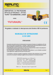
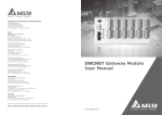
I
Lettore esterno carte
transponder 44..GA01-T e 44..GA01-M
INTRODUZIONE
Il lettore esterno di card transponder è un dispositivo stand-alone da
posizionare fuori dalla porta della camera, in grado di gestire autonomamente:
- il controllo degli accessi ai locali dell’albergo (camere, locali di serv zio, aree comuni e accessi a scalare;
- il sinottico stato camera posto sul fronte del dispositivo;
- l’attuazione della luce di cortesia;
- l’attuazione di un eventuale avvisatore acustico (campanello);
- la ripetizione di una segnalazione di camera occupata.
CARATTERISTICHE TECNICHE
•Contenitore: 3 moduli Sistema 44 (67,5 l x 45 h x 55,5 p) mm
•Sporgenza max da filo-frutti: 9 mm (da filo placca)
•Grado di protezione: IP 40
•Morsettiere: estraibili 12A - 250V
•Condizioni climatiche: -10°C a +50°C - 2000m s.l.m.
•Tensione di alimentazione: 12Vac/dc
•Assorbimento massimo (@ 12Vdc): 150mA
•Assorbimento massimo (@ 12Vac): 250mArms
Descrizione Morsettiera
Morsetto A-B
Bus di camera (polarizzato)
Morsetto -
Negativo alimentazione (comune ingressi)
Morsetto +
Positivo alimentazione
Morsetto 1
Ingresso rilevazione “stato camera”
Morsetto 2
Ingresso pulsante “luce cortesia”
Morsetto 3-4
Uscita relè attuazione “luce cortesia”
Morsetto 5
COM (Comune uscite 6, 7 e 8)
Morsetto 6
Uscita relè attuazione “elettro-serratura”
Morsetto 7
Uscita relè attuazione “campanello”
Morsetto 8 Uscita relè ripetizione “ospite presente”
Morsetto 8
Uscita relè ripetizione “Velocità 3 Fan-Coil”
ATTENZIONE:
Effettuare il cablaggio dei fili PRIMA di collegare le morsettiere nel dispositivo.
Configurazione iniziale dei lettori mediante carta master
ATTENZIONE: Utilizzare questa procedura se l’impianto non prevede
l’utilizzo del software art. SFW-ALB04.
I lettori vengono forniti privi di parametri di configurazione (tipologia lettore, codice impianto, n. lettore ecc…). La programmazione dei parametri di configurazione avviene attraverso la carta MASTER (art.
44339CHM-T) fornita un codice impianto predefinito e non alterabile
dall’utente. Per configurare il dispositivo è necessario avvicinare brevemente la carta master quando il lettore è nella condizione di default in
cui L1 lampeggia (rosso). Se la carta master viene letta correttamente,
ATTENZIONE:
I dispositivi con tecnologia MIFARE
(art. 44…GA01-M e art. 44…
GA30-M ) non devono essere
installati abbinati con le placche
aventi le cornici CROMO (CR).
Per ulteriori informazioni
contattare il Servizio di Assistenza
Tecnica al fine di procedere con l’ordinazione di cornice verniciata.
il lettore si configura segnalandolo con l’emissione di un beep e con
tre lampeggi simultanei di L1 e L2 dopodiché entra in modalità
Generazione di carte accessi. In fase di lettura della carta master il lettore scrive nella propria memoria il codice impianto e il numero lettore.
Mentre il primo parametro è fisso (codice impianto), il secondo parametro (n. lettore) viene incrementato ogni volta che si configura un lettore privo di parametri di configurazione. Di default la carta master ha
come prima configurazione il numero camera uguale ad 1.
Nota:
Utilizzare solo una master per effettuare la configurazione del sistema
onde evitare accessi doppi.
Nota:
Ogni volta che la carta viene letta correttamente, il lettore lo segnala
con l’emissione di un beep Diversamente emette tre beep di errore, in
questo caso attendere 60 secondi è ricominciare la procedura.
Configurazione della tipologia di funzionamento
ATTENZIONE: Prima di procedere con la “Configurazione della tipologia di funzionamento” è necessario effettuare la “Configurazione iniziale
dei lettori”.
Tipologia
Segnalazione L1
Configurazione
LETTORE DI
CAMERA
Un breve lampeggio
da 0,1s (ON) e 2s
(OFF).
Dalla condizione di normale funzionamento L1
lampeggiante (verde) avvicinare tre volte la
carta master.
LETTORE
LOCALE DI
SERVIZIO
Due brevi lampeggi
da 0,1s (ON) e 2s
(off).
Dalla condizione di normale funzionamento L1
lampeggiante (verde) avvicinare tre volte la carta
master e premere una volta il pulsante frontale.
La tipologia è segnalata in fase di configurazione con: L1 (arancio) - L2 (rosso)
Confermare avvicinando la carta master.
LETTORE
AREE
COMUNI
Tre brevi lampeggi da
0,1s (ON) e 2s (OFF).
Dalla condizione di normale funzionamento L1
lampeggiante (verde) avvicinare tre volte la carta
master e premere due volte il pulsante frontale.
La tipologia è segnalata in fase di configurazione con: L1 (arancio) - L3 (giallo).
Confermare avvicinando la carta master.
LETTORI
ACCESSI
SCALARE
Quattro brevi lampeggi da 0,1s (ON) e 2s
(OFF).
Dalla condizione di normale funzionamento L1
lampeggiante (verde) avvicinare tre volte la carta
master e premere due volte il pulsante frontale.
La tipologia è segnalata in fase di configurazione con: L1 (arancio) - L2 (rosso) e L3 (giallo).
Confermare avvicinando la carta master.
Nota:
Tutti i servizi associati al termostato ed al lettore interno, nelle tipologie
di funzionamento diverse da LETTORE DI CAMERA non sono abilitati.
Generazione di carte accessi
Tipologia
Configurazione
CLIENTE
Dalla condizione di normale funzionamento
L1 lampeggiante (verde) avvicinare una volta
la carta master. Successivamente avvicinare
una carta utente e dopo circa un secondo il
lettore emetterà un beep di conferma. Creare
ulteriori carte cliente avvicinando altre carte
utente, oppure uscire dalla modalità di programmazione avvicinando la carta master.
CAMERIERA
Dalla condizione di normale funzionamento
avvicinare una volta la carta master e premere
una volta il pulsante frontale. Successivamente
avvicinare una carta utente e dopo circa un secondo il lettore emetterà un beep di conferma.
Creare ulteriori carte cameriera avvicinando
altre carte utente, oppure uscire dalla modalità
di programmazione avvicinando la carta master.
MANUTENTORE
Dalla condizione di normale funzionamento avvicinare una volta la carta master
e premere due volte il pulsante frontale.
Successivamente
avvicinare
una
carta utente e dopo circa un secondo il lettore emetterà un beep di conferma.
Creare ulteriori carte manutentore avvicinando
altre carte utente, oppure uscire dalla modalità
di programmazione avvicinando la carta master.
PASSEPARTOUT
Dalla condizione di normale funzionamento
avvicinare una volta la carta master e premere
tre volte il pulsante frontale. Successivamente
avvicinare una carta utente e dopo circa un secondo il lettore emetterà un beep di conferma.
Creare ulteriori carte passepartout avvicinando
altre carte utente, oppure uscire dalla modalità
di programmazione avvicinando la carta master.
SUPER-GUEST
Dalla condizione di normale funzionamento avvicinare una volta la carta master e premere quattro volte il pulsante frontale. Successivamente
avvicinare una carta utente e dopo circa un secondo il lettore emetterà un beep di conferma.
Creare ulteriori carte super-guest avvicinando
altre carte utente, oppure uscire dalla modalità
di programmazione avvicinando la carta master.
Segnalata in fase
di configurazione
con: L1 (verde)
Segnalata in fase
di configurazione
con: L1 (verde) e
L2 (rosso)
Segnalata in fase
di configurazione
con: L1 (verde) e
L3 (giallo)
Segnalata in fase
di configurazione
con: L1 (verde),
L2 (rosso) e L3
(giallo)
G
Transponder card external
reader 44..GA01-T e 44..GA01-M
INTRODUCTION
The transponder card external reader is a stand-alone device to be
positioned outside the door of the room. Said reader is capable of
independently managing:
- access to the hotel premises (rooms, service premises, common
areas and scalable access;
- the room status summary provided for at the front part of the device;
- actuation of the courtesy light;
- actuation of possible acoustic signal (bell);
- repetition of a room occupied signal.
CARATTERISTICHE TECNICHE
• Container: 3 Sistema 44 (67.5 l x 45 h x 55.5 p) mm modules
• Maximum extension from components wire: 9 mm (from plate wire)
• Degree of protection: IP 40
• Terminal boards: extractable 12A - 250V
• Climatic conditions: -10°C to +50°C - 2000m a.s.l.
• Power supply voltage: 12Vac/dc
• Maximum absorption (@ 12Vdc): 150mA
• Maximum absorption (@ 12Vac): 250mArms
Description of terminal board
Terminal A-B
Room Bus (polarised)
Terminal -
Negative supply (common inputs)
Terminal +
Positive supply
Terminal 1
Detection input “room status”
Terminal 2
“Courtesy light” button input
Terminal 3-4
“Courtesy light” actuation relay output
Terminal 5
COM (Common outputs 6, 7 and 8)
Terminal 6
“Electric locking” actuation relay output
Terminal 7
“Bell” actuation relay output
Terminal 8
“Guest in” repetition relay output
Segnalata in fase
di configurazione
con: L1 (verde)
e L2 (rosso)
lampeggiante
Nota:
Se durante la fase di codifica il lettore accende L1 di colore rosso ed
attiva per tre volte il buzzer anziché far lampeggiare solamente L1 di
colore verde, significa che la programmazione della carta non è andata
a buon fine ed è quindi necessario ripeterla.
Nota:
La creazione di una nuova carta cliente invalida le carte cliente precedentemente generate
CAUTION:
Cable the wires before connecting the terminal boards in the device.
Initial configuration of the readers using the master card
WARNING: Follow this procedure in case the system does not provide
for using software art. SFW-ALB04.
Readers are provided without configuration parameters (type of reader,
system code, reader number etc…). Configuration parameters are programmed by means of the MASTER card (art. 44339CHM-T) provided
with a predefined system code which cannot be modified by the user.
To configure the device, briefly near the master card when the reader is
in the default status with L1 blinking (red). Should the master card be
read correctly, the reader is configured signalling such successful rea-
Note:
All services associated to the thermostat and to the internal reader, are not
enabled in types of operation different from the ROOM READER type.
Generazione di carte accessi
Type
CLIENT
WAITER
From the normal operating condition near the
master card once and press the front button once.
Subsequently near the user card and
the reader shall emit a confirmation beep after about one second.
Create other waiter cards by nearing other
user cards, or exit from the programming mode by nearing the master card.
MAINTANANCE
PERSONNEL
From the normal operating condition near the master card once and press the front button twice.
Subsequently near the user card and
the reader shall emit a confirmation beep after about one second.
Create other maintenance personnel cards by
nearing other user cards, or exit from the programming mode by nearing the master card.
PASSEPARTOUT
From the normal operating condition near the master card once and
press the front button three times.
Subsequently near the user card and
the reader shall emit a confirmation beep after about one second.
Create other passepartout cards by nearing
other user cards, or exit from the programming mode by nearing the master card.
SUPER-GUEST
From the normal operating condition near the master card once and press the front button four times.
Subsequently near the user card and
the reader shall emit a confirmation beep after about one second.
Create other super-guest cards by nearing
other user cards, or exit from the programming mode by nearing the master card.
WARNING:
M I FA R E t e c n h o l o g y d e v i c e s
(art. 44..GA01-M e art. 44..GA30-M)
shall not be installed combined
with plates having CHROMEPLATED (CR) frames.
For further information, please contact
the Technical assistance department
so as to order painted frames.
ding by emitting a beep alongside L1 and L2 simultaneously blinking
three times, after which it enters the access cards generation mode.
When reading the master card, the reader enters the system code and
reader number into its memory. While the first parameter is fixed (system
code), the second parameter (reader number) increases each time a
reader without configuration parameters is configured. As first configuration, the master card has a default room number equivalent to 1.
Note:
Use only one master to configure the system so as to avoid double
access.
Note:
Each time the card is read correctly, the reader signals such successful reading by emitting a beep. Otherwise the reader emits three error
beeps. In the latter case, wait for 60 seconds and start the procedure
over again.
Configuring the type of operation
WARNING: Before going ahead with the “Configuring the type of operation” procedure ensure that you have performed the “Initial reader
configuration” operation.
TYPE
Signal L1
configuration
ROOM
READER
Brief 0.1s
(ON) and 2s
(OFF) blinks.
From the normal operating condition - L1 blinking (green) near the master card three times.The type is signalled during the configuration step with: L1 (orange) Default status
Confirm by nearing the master card.
SERVICE
PREMISES
READER
Two brief
0.1s (ON)
and 2s (OFF)
blinks.
From the normal operating condition - L1 blinking (green)
- near the master card three times and press the front
button once.
The type is signalled during the configuration step with:
L1 (orange) - L2 (red)
Confirm by nearing the master card.
COMMON
AREAS
READERS
Three brief
0.1s (ON)
and 2s (OFF)
blinks.
From the normal operating condition - L1 blinking (green)
- near the master card three times and press the front
button twice.
The type is signalled during the configuration step with: L1
(orange) - L3 (yellow).
Confirm by nearing the master card.
SCALABLE
ACCESS
READERS
Four brief
0.1s (ON)
and 2s (OFF)
blinks.
From the normal operating condition - L1 blinking (green)
- near the master card three times and press the front
button twice.
The type is signalled during the configuration step with:
L1 (orange) - L2 (red) and L3 (yellow).
Confirm by nearing the master card.
configuration
From the normal operating condition - L1
blinking (green) - near the master card once.
Subsequently near the user card and
the reader shall emit a confirmation beep after about one second.
Create other client cards by nearing other
user cards, or exit from the programming mode by nearing the master card.
Signalled during
the configuration
step with:
L1 (green)
Signalled during
the configuration
step with:
L1 (green) and
L2 (red)
Signalled during
the configuration
step with:
L1 (green) and
L3 (yellow)
Signalled during
the configuration
step with:
L1 (green), L2
(red) and L3
(yellow)
Signalled during
the configuration
step with:
L1 (green) and L2
(red) blinking
Note:
When encoding the reader, should L1 light up indicating red colour
and activate the buzzer three times instead of L1 blinking just once,
this means that the card programming operation was not successful
and thus should be repeated.
Note:
Creation of a new client card invalidates the previously generated
client cards
Schema elettrico
Electrical diagram
-/~
+/~
12V
INCONTRO ELETTRICO
230V~
230V~
~
DALLE
PROTEZIONI
~
PREVISTE
PORTATA RELE'
MAX 1A
~
DALLE
PROTEZIONI
~
PREVISTE
230V~
~
CAMPANELLO
PORTATA RELE'
MAX 1A
CORT.
LINEA LUCE
CORTESIA
~
SEGNALAZIONE
OSPITE PRESENTE
PORTATA RELE'
MAX 1A
PORTATA RELE'
MAX 1A
5349
44...GA01-T / M
230V~
3
~
2° SECONDARIO
12V~
12V~
~
~
6
7
8
DO NOT
DISTURB
1° SECONDARIO
5
4
~
+
1
2
CORT.
PULSANTE
COMANDO
L. CORTESIA
N.A.
INGRESSO
OSPITE PRESENTE
N.A.
-/~
+/~
C.558 - 00 - 260110
Avvertenze I prodotti devono essere commercializzati in confezione originale,
in caso contrario al rivenditore e/o installatore è fatto obbligo di applicare e di
trasmettere all'utilizzatore le istruzioni d'uso che accompagnano il prodotto.
Dopo aver aperto l'imballaggio, assicurarsi dell'integrità dell'apparecchio, nel
dubbio non utilizzare l'apparecchio e rivolgersi a personale professionalmente
qualificato. L'apparecchio, anche se imballato, deve essere maneggiato con
cura e immagazzinato in luogo asciutto ad una temperatura compresa tra
–5…+40°C.
Si ricorda inoltre: • La garanzia di 5 anni si applica per difetti e non conformità di
prodotto imputabili al costruttore fermi restando i diritti e gli obblighi derivanti dalle disposizioni
legislative vigenti (artt. 1490, 1512 C.C., DL 24/2002, Direttiva 1999/44/CE, art. 1519 C.C.). Il
difetto deve essere denunciato entro due mesi dalla data della scoperta dello stesso. I cinque anni
si intendono dal momento della consegna del prodotto da parte di AVE. • I prodotti AVE sono
prodotti da installazione. Vanno installati da personale qualificato conformemente alle normative
impianti. • Togliere tensione agendo sull'interruttore generale prima di operare sull'impianto. •
Curare in modo particolare la preparazione dei terminali dei cavi da inserire nei morsetti dell'apparecchio per evitare la riduzione delle distanze di isolamento tra gli stessi. • Serrare le viti dei morsetti con cura per evitare surriscaldamenti che potrebbero provocare un incendio o il danneggiamento dei cavi. • Il prodotto, è destinato all'utilizzo in luoghi asciutti e non polverosi. Per ambienti
particolari utilizzare prodotti specifici. •È possibile il pericolo di scossa elettrica o di malfunzionamento se l’apparecchio viene manomesso. • Installare prodotti e accessori secondo le prescrizioni del catalogo e dei fogli istruzione appositi oltre che in conformità a norme e leggi specifiche.
Note Products should be sold in their original packaging. When this is not the case, the retailer or/
and the installer is obliged to follow, as well as communicate to the user, the instructions for use
which are supplied with the product. After opening the packaging, check that the appliance is
undamaged. Do not use the appliance if there is any doubt, but contact a qualified technician.
Even before unpacking, the appliance should be handled with care and stored in a dry place at
temperatures between –5°C and +40°C.
Also note: • The 5 years warranty is applicable for any defect in or failing of the goods caused by
the manufacturer’s negligence. It doesn’t affect your statutory rights as prescribed by law (art.
1490, 1512 C.C., DL 24/2002, Directive 1999/44/CE, art. 1519 C.C.). The defect must be notified
within 2 month from the date it was discovered. Five years are intended from the date of delivery
of the goods by AVE. • AVE products are installation products. They must be installed by skilled
workers in compliance with the installation regulations. • Before carrying out any maintenance on
the appliance, cut off the mains power. • Special care should be taken in the preparation of the
cable terminals to be inserted into the appliance terminals so as to maintain sufficient isolation
distance between them. • When tightening the terminal screws, special care should be taken to
avoid overheating which could start a fire or damage the cables. • The product must be used in
dry, dust-free areas. Suitable products must be used in any other conditions. • There is the possibility of electric shocks or failure of the device if the device is tampered with. • Install products and
accessories according to the prescriptions of the catalogue and the instructions sheet and in
compliance with specific standards and rules.