1
170.IU0.XKS.000
10-99
r USER MANUAL
r ISTRUZIONI D'USO
TKS - MKS
INDEX
GB
MOUNTING REQUIREMENTS ........................................ 1
CONNECTIONS ............................................................... 1
PRELIMINARY HARDWARE SETTINGS ........................ 6
INSTRUMENT CONFIGURATION ................................... 8
Configuration procedure .......................................... 8
RUN TIME MODE .......................................................... 16
Display function ...................................................... 16
Indicators ............................................................... 16
Pushbutton functionality during
operative mode ...................................................... 16
Enable/disable the control output .......................... 17
Manual function ...................................................... 17
Out 1 failure detection function .............................. 18
Loop break alarm function ..................................... 18
SP/SP2 selection ................................................... 18
Direct access to the set point ................................ 19
Serial link ................................................................ 19
SMART function ..................................................... 19
Lamp test ............................................................... 19
RUN TIME PARAMETERS ............................................ 20
ERROR MESSAGES ..................................................... 22
GENERAL INFORMATIONS .......................................... 24
MAINTENANCE ............................................................. 24
DEFAULT PARAMETERS ............................................ A.1
SECURITY CODES ....................................................... A.2
INDICE
I
MONTAGGIO ................................................................... 1
COLLEGAMENTI ELETTRICI .......................................... 1
IMPOSTAZIONI HARDWARE PRELIMINARI ................. 6
CONFIGURAZIONE DELLO STRUMENTO .................... 8
Procedure di configurazione .................................... 8
Parametri di configurazione ..................................... 9
MODO OPERATIVO ...................................................... 16
Funzionalità del visualizzatore ............................... 16
Indicatori ................................................................. 16
Operatività dei tasti durante
il modo operativo .................................................... 16
Abilitazione/disabilitazione
dell'uscita di regolazione ........................................ 17
Funzionamento in modo MANUALE ...................... 17
Allarme di anomalia sull'uscita 1 ............................ 18
Funzione loop break alarm (LBA) .......................... 18
Selezione del set point operativo ........................... 18
Modifica diretta del set point .................................. 18
Interfaccia seriale ................................................... 19
Funzione SMART ................................................... 19
Lamp test ............................................................... 19
PARAMETRI OPERATIVI .............................................. 20
MESSAGGI DI ERRORE ............................................... 22
CARATTERISTICHE TECNICHE .................................. 24
MANUTENZIONE ........................................................... 24
DEFAULT PARAMETERS ............................................ A.1
SECURITY CODES ....................................................... A.2
OUTLINE AND CUT OUT DIMENSIONS
DIMENSIONI E FORATURA
Fig. A1
TKS
Fig. A2
MKS
CONNECTION DIAGRAMS
Connections are to be made with the instrument housing
installed in its proper location.
COLLEGAMENTI ELETTRICI
I collegamenti devono essere effettuati dopo che la
custodia dello strumento è stata regolarmente montata sul
pannello
Fig. B TKS - MKS
MOUNTING REQUIREMENTS
CONNECTIONS
These instruments are intended for permanent installation,
for indoor use only, in an electrical panel which encloses
the rear housing, exposed terminals and wiring on the
back.
Select a mounting location where the instrument is subject
to minimum vibration and the ambient temperature range
is between 0 and 50 °C.
These instruments can be mounted on a panel up to 15
mm thick with a square cutout of 45 x 92 (TKS) mm or
92 x92 (MKS) mm.
For outline and cutout dimensions refer to Fig. 2.
The surface texture of the panel must be better than
6,3 µm.
The instrument is shipped with rubber panel gasket.
To assure the IP65 and NEMA 4 protection, insert the
panel gasket between the instrument and the panel as
shown in fig. 1.
While holding the instrument against the panel proceed as
follows:
1) insert the gasket in the instrument case;
2) insert the instrument in the panel cutout;
3) pushing the instrument against the panel, insert the
mounting bracket;
4) with a screwdriver, turn the screws with a torque
between 0.3 and 0.4 Nm.
A) MEASURING INPUTS
NOTE: Any external components (like zener barriers etc.)
connected between sensor and input terminals may cause
errors in measurement due to excessive and/or not
balanced line resistance or possible leakage currents.
TC INPUT
+ 1
_ 3
Shield
+ 1
_ 3
Shield
Fig. 2 THERMOCOUPLE INPUT WIRING
screw
External resistance: 100 Ω max, maximum error 0.1% of
span.
Cold junction: automatic compensation from 0 to 50 °C.
Cold junction accuracy: 0.1 °C/°C
Input impedance: > 1 MΩ
panel
bracket
gasket
NOTES:
1) Don’t run input wires together with power cables.
2) For TC wiring use proper compensating cable
preferable shielded.
3) when a shielded cable is used, it should be connected
at one point only.
screw
bracket
Fig. 1
GB
1
RTD INPUT
LINEAR INPUT
RTD
RTD
1
+
3
_
mA,
mV
or
V
Shield
4
3
1
4
3
1
+
3
_
1
mA,
mV
or
V
G
Fig. 3 RTD INPUT WIRING
Fig. 4 mA, mV AND V INPUTS WIRING
Input: for RTD Pt 100 Ω, 3-wire connection.
Line resistance: automatic compensation up to 20 Ω/wire
with no measurable error.
NOTES:
1) Don’t run input wires together with power cables.
2) Pay attention to the line resistance; a high line
resistance may cause measurement errors.
3) When shielded cable is used, it should be grounded at
one side only to avoid ground loop currents.
NOTES:
1) Don’t run input wires together with power cables.
2) Pay attention to the line resistance; a high line
resistance may cause measurement errors.
3) When shielded cable is used, it should be grounded at
one side only to avoid ground loop currents.
4) The resistance of the 3 wires must be the same.
GB
Input type
11
12
13
14
15
16
17
18
2
0 - 60 mV
12 - 60 mV
0 - 20 mA
4 - 20 mA
0- 5 V
1- 5 V
0 - 10 V
2 - 10 V
impedance
Accuracy
> 1 MΩ
<5Ω
> 200 kΩ
> 400 kΩ
0.2 % + 1 digit
@ 25°C
B) LOGIC INPUT
CURRENT TRANSFORMER INPUT
This input allows to measure and display the current
running through the load, driven by the OUTPUT 1, during
the ON and the OFF period of the OUT 1 cycle time.
By this features it is also available the "Out 1 failure
detection" function (see page 18)
SP / SP2
8
7
5
Fig. 5 - LOGIC INPUT WIRING
6
Current
transformer
This logic input allows to select the operative set point.
logic input
op. set point
open
SP
close
SP2
Load
Safety notes:
1) Do not run logic input wiring together with power
cables.
2) Use an external dry contact capable of switching 0.5
mA, 5 V DC.
3) The instrument needs 100 ms to recognize a contact
status variation.
4) The logic input is NOT isolated by the measuring input
Fig. 6
CURRENT TRANSFORMER INPUT
WIRING
NOTES:
1) The input impedance is equal to 10 Ω.
2) The maximum input current is equal to 50 mA (50 / 60
Hz).
3) The minimum period (ON or OFF) to perform this
measurement is equal to 400 ms.
Scaling: programmable from 10 A to 100 A (with 1A step).
Resolution:
- for full scale up to 20 A: 0.1 A.
- for full scale from 21 A to 100 A: 1 A
Safety note:
- Do not run current transformer input wiring together
with power cables.
GB
3
C) RELAY OUTPUTS
VOLTAGE OUTPUT FOR SSR DRIVE
16
NO - OUT 3
17
NO - OUT 4
18
C - OUT 3 e 4
19
NO - OUT 2
+
OUT 3
14
OUT 1
OUT 4
OUT 2
20
15
C - OUT 1
22
NO - OUT 1
+
_
SOLID STATE
RELAY
Fig. 8 SSR DRIVE OUTPUT WIRING
It is a time proportioning output.
Logic level 0: Vout < 0.5 V DC.
Logic level 1:
- 14 V + 20 % @ 20 mA
- 24 V + 20 % @ 1 mA.
Maximum current = 20 mA.
NOTES:
1) This output is not isolated. A double or reinforced
isolation between instrument output and power supply
must be assured by the external solid state relay.
2) Relay output and SSR drive output are both available.
For the SSR output selection see "Preliminary
hardware settings" chapter.
C - OUT 2
21
_
OUT 1
Fig. 7 RELAY OUTPUTS WIRING
The outputs 1 and 2 are protected by varistor against
inductive load with inductive component up to 0.5 A.
The contact rating of the OUT 1 is 3A/250V AC resistive
load.
The contact rating of the OUT 2, 3 and 4 is 2A/250V AC
resistive load.
The number of operations is 1 x 10⁵ at specified rating.
NOTES:
1) To avoid electrical shock, connect power line at the
end of the wiring procedure.
2) For power connections use No 16 AWG or larger wires
rated for at last 75 °C.
3) Use copper conductors only.
4) Don’t run input wires together with power cables.
5) Relay output and SSR drive output are both available.
For the relay output selection see "Preliminary
hardware settings" chapter.
GB
4
D) POWER LINE WIRING
11
10
9
A/A'
12
A'/A
B/B'
B'/B
COMMON
M
A
S
T
E
R
L (L1)
Fig. 10 POWER LINE WIRING
100V to 240V AC 50/60Hz (-15% to + 10% of the nominal
value).
24 V AC/DC (+ 10 % of the nominal value).
NOTES:
1) Before connecting the instrument to the power line,
make sure that line voltage corresponds to the
description on the identification label.
2) To avoid electrical shock, connect power line at the
end of the wiring procedure.
3) For supply connections use No 16 AWG or larger wires
rated for at last 75 °C.
4) Use copper conductors only.
5) Don’t run input wires together with power cables.
6) For 24 V DC the polarity is a do not care condition.
7) The power supply input is NOT fuse protected.
Please, provide it externally.
Power supply
Type
Current
Voltage
24 V AC/DC
T
500 mA
250 V
100/240 V AC
T
63 mA
250 V
When fuse is damaged, it is advisable to verify the
power supply circuit, so that it is necessary to send
back the instrument to your supplier.
8) The safety requirements for Permanently Connected
Equipment say:
- a switch or circuit-breaker shall be included in
the building installation;
- It shall be in close proximity to the equipment
and within easy reach of the operator;
- it shall be marked as the disconnecting device for the
equipment.
NOTE: a single switch or circuit-breaker can drive more
than one instrument.
9) When a neutral line is present, connect it to terminal
13.
Fig. 9 - RS-485 WIRING
The cable length must not exceed 1.5 km at 9600 BAUD.
NOTES:
1) This is an RS485 isolated interface.
2) The following report describes the signal sense of the
voltage appearing across the interconnection cable
as defined by EIA for RS-485.
a) The ”A” terminal of the generator shall be negative
with respect to the ”B” terminal for a binary 1 (MARK
or OFF) state.
b) The ”A” terminal of the generator shall be positive
with respect to the ”B” terminal for a binary 0
(SPACE or ON)
GB
N (L2)
N (L2)
I
N
S
T
R
U
M
E
N
T
13
L (L1)
SERIAL INTERFACE
RS-485 interface allows to connect up to 30 devices with
one remote master unit.
5
PRELIMINARY HARDWARE SETTINGS
MAIN INPUT SELECTION
How to remove the instrument from its case
1) Switch off the instrument.
2) Push gently the lock A on the right.
If an input different from TC-RTD input (standard) is desired,
remove the instrument from its case and set J1 according to
the following table.
INPUT
A
3) While the lock A is maintained out, slide out the right
side of the instrument.
J1
TYPE
1-2
3-4
5-6
7-8
TC-RTD
open
close
open
open
9-10
open
60 mV
open
close
open
open
open
5V
close
open
close
open
open
10 V
open
open
close
open
open
20 mA
open
open
open
close
close
NOTE: the jumper not used can be placed on pin 7-9
2 4 6 8 10
1 3 5 7
J1
9
A
4) Push gently the lock B on the left.
5) While the lock B is maintained out, slide out the
instrument.
B
Fig. 11
GB
6
OPEN INPUT CIRCUIT
This instrument is able to identify the open circuit for TC
and RTD inputs.
The open input circuit condition for RTD input is shown as
an "overrange" condition.
For TC input, it is possible to select overrange indication
(standard) or underrange indication setting the CH2 and
SH2 according to the following table:
Overrange (STD)
Underrange
CH2 = close
CH2 = open
SELECTION OF THE OUT 1 TYPE
The output 1 can be set, by J303, as SSR output (1- 2) or
relay output (2 - 3).
When the relay output is selected, by J302 it is possible to
select the contact used (N.O. = 1-2 or N.C = 2-3) as
shown below:
SH2 = open
SH2 = close
1
Both pads are located on the soldering side of the CPU
card
2 3
SSR
3
2
J303
J302
NOTE: The "Error messages" paragraph gives full
details of the instrument behaviour when an out
of range condition is displayed.
SH2
CH2
Fig. 16
Fig. 12
GB
1 2 3
RELAY
7
1
INSTRUMENT CONFIGURATION
b) By the s or t key it is possible to select between:
Run time and configuration modes
When the instrument is in run time mode and no
modification parameter is in progress, the measured
variable is shown on the upper display, while the set point
is shown on the lower display (we define this condition
"normal display mode").
= (monitor) this selection allows to monitor
but not to modify the value of all
configuration parameters.
= (modify) this selection allows to monitor
and to modify the value of all
configuration parameters.
c) Push the FUNC pushbutton.
General note about graphic symbols used for
mnemonic code visualization.
The instrument displays some characters with special
symbols.
The following table shows the correspondence between
the symbols and the characters.
symbol
character
"
"
k
"
"
W
"
"
m
"
"
Z
"
"
V
"
"
J
NOTES:
1) During monitor mode, the instrument continues to
operate as in run time mode and if no push-button is
depressed for more than 10 s (or 30 s according to
P39 [time out selection"]), the instrument returns
automatically to the normal display mode.
2) When modify mode is started, the instrument stops the
control and:
- sets control outputs to OFF;
- sets alarms in no alarm condition;
- disables the serial link;
- the time out will be removed.
3) If the configuration group is protected by security code
the display will show:
CONFIGURATION PROCEDURE
At power up, the instrument starts in the same mode
(configuration or run time) it was prior to the power OFF.
By s and t keys enter a value equal to the security
code set for the configuration mode or the passepartout code (see appendix A).
Note: the passe-partout code allows to enter in modify
configuration parameters mode either if any other
configuration security code is set or if the configuration
parameters are always protected (P51 = 1).
When it is desired to go from run-time mode to
configuration mode proceed as follows:
a) keep depressed the FUNC pusbutton and push the
MAN pushbutton. Maintain the pressure on both
pushbuttons for more than 4 seconds, the upper
display will show:
When it is desired to exit from configuration modify mode
proceed as follows:
a) Push "FUNC" or "MAN" push-button more times until
the "C.End" parameter is displayed.
b) Pushing ”s” or “t” push-button select the "YES"
indication.
The same indication will be shown when the instrument
starts in configuration mode.
GB
8
c) Push “FUNC” push-button. The instrument ends the
configuration modify mode, preforms an automatic
reset and restarts in the run time mode.
SEr1 = Serial interface protocol
OFF
= No serial interface
Ero
= Polling/selecting ERO
nbUS = Modbus
jbUS
= Jbus
Pushbutton function during configuration mode
FUNC =
This will memorize the new value of the
selected parameter and go to the next
parameter (increasing order).
MAN =
This will scroll back the parameters without
memorization of the new value.
s
=
This will increase the value of the selected
parameter
t
=
This will decrease the value of the selected
parameter.
SEr2 = Serial link device address
Not available when SEr1 = OFF
From 1 to 95 for ERO protocol
From 1 to 255 for all the other protocols
NOTE: the electrical characteristic of the RS 485 serial
interface will allow the connection of 31 devices maximum.
SEr3 = Baud rate for serial link
Not available when SEr1 = OFF
From 600 to 19200 baud.
NOTE: 19200 baud is shown on display as 19.20.
CONFIGURATION PARAMETERS
Notes:
1) In the following pages we will describe all the
parameters of the instrument but the instrument will
show only the parameters related with the specific
hardware and in accordance with the specific
instrument configuration (i.e. setting OUT 3 equal to 0
(not used), all the parameters related with alarm 2 will
be skipped).
2) During configuration mode, the lower display shows
the mnemonic code of the selected parameter while
the upper display shows the value or the status
assigned to the selected parameter.
SEr4 = Byte format for serial link
Not available when SEr1 = OFF
7E = 7 bits + even parity (For ERO protocol only)
7O = 7 bits + odd parity (For ERO protocol only)
8E = 8 bits + even parity
8O = 8 bits + odd parity
8
= 8 bits without parity
P1 - Input type and standard range
0 = TC type
L
range
0
1 = TC type
L
range
0
2 = TC type
J
range -100.0
3 = TC type
J
range
-100
4 = TC type
K
range -100.0
5 = TC type
K
range
-100
6 = TC type
N
range
-100
7 = TC type
R
range
0
8 = TC type
S
range
0
9 = RTD type Pt 100 range -199.9
10 = RTD type Pt 100 range
-200
11 = mV
Linear range
0
12 = mV
Linear range
12
13 = mA
Linear range
0
dF.Cn = Default configuration parameter
loading
Available in modify configuration parameters only
OFF = No loading data
tb1 = Loading European Table default parameters.
tb2 = Loading American Table default
parameters.
NOTE: the list of both default parameter tables is reported
at Appendix A.
GB
9
/
/
/
/
/
/
/
/
/
/
/
/
/
/
+400.0 °C
+900 °C
+400.0 °C
+1000 °C
+400.0 °C
+1370 °C
+1400 °C
+1760 °C
+1760 °C
+400.0 °C
+800 °C
60 mV
60 mV
20 mA
14 = mA
Linear range
4 /
20 mA
15 = V
Linear range
0 /
5V
16 = V
Linear range
1 /
5V
17 = V
Linear range
0 /
10 V
18 = V
Linear range
2 /
10 V
19 = TC type
L
range
0 /
+1650 °F
20 = TC type
J
range
-150 /
+1830 °F
21 = TC type
K
range
-150 /
+2500 °F
22 = TC type
N
range
-150 /
+2550 °F
23 = TC type
R
range
0 /
+3200 °F
24 = TC type
S
range
0 /
+3200 °F
25 = RTD type Pt 100 range -199.9 / +400.0 °F
26 = RTD type Pt 100 range
-330 /
+1470 °F
27 = TC type
T
range -199.9 /
400.0 °C
28 = TC type
T
range
-330 /
750 °F
NOTE: selecting P1 = 0, 2, 4, 9, 25 or 27, the instrument
set automatically P40 = FLtr. For all the remaining ranges
it will set P40 = nOFL.
Notes:
1) When this parameter is modified, rH parameter will be
re-aligned to it.
2) If a linear input is selected, the value of this parameter
can be smaller than P3 in order to get a reverse
readout.
The initial and full scale values determine the input span
which is used by the PID algorithm, the SMART and the
alarm functions.
NOTE: the minimum input span (S = P4 - P3), in absolute
value, should be set as follows:
- For linear inputs, S > 100 units.
- For TC input with °C readout, S > 300 °C.
- For TC input with °F readout, S > 550 °F.
- For RTD input with °C readout, S > 100 °C.
- For RTD input with °F readout, S > 200 °F.
P5 = Output 1 type
Changing the P5 setting, also Cy1 parameter will be
automatically modified.
rEL = Relay [the cycle time (Cy1) will be forced to
15 s]
SSr = SSR [the cycle time (Cy1) will be forced to 4 s]
P2 = Decimal point position
This parameter is available only when a linear input is
selected (P1 = 11 to 18).
= No decimal figure.
= One decimal figure.
= Two decimal figures.
= Three decimal figures.
----.
---.--.--.---
P3 = Initial scale value
For linear inputs it is programmable from -1999 to 4000.
For TC and RTD input it is programmable within the input
range.
Notes:
1) When this parameter is modified, rL parameter will be
re-aligned to it.
2) If a linear input is selected, the value of this parameter
can be greater than P4 in order to get a reverse
readout.
P6 = Output 1 action
This parameter is skipped if P7 = 4
rEV = Reverse action (Heating action)
dir = Direct action (Cooling action)
Reverse
Direct
INPUT
INPUT
t
OUTPUT
t
P4 = Full scale value
For linear inputs it is programmable from -1999 to 4000.
For TC and RTD inputs, it is programmable within the
input range.
GB 10
t
OUTPUT
t
P7 = Output 2 function.
0 = output not used.
1 = it is used as Alarm 1 output and the alarm 1 is
programmed as process alarm.
2 = it is used as Alarm 1 output and the alarm 1 is
programmed as band alarm.
3 = it is used as Alarm 1 output and the alarm 1 is
programmed as deviation alarm.
4 = it is used as secondary control output (Cooling
output).
NOTE: setting P7 = 4, the P6 parameter is forced to "rEV".
P8 = Cooling media.
Available only when P7 = 4
- AIr = Air is used as cooling media.
- OIL = Oil is used as cooling media.
- H2O = Direct water is used as cooling media.
Changing P8 parameter, the instrument forces the cycle
time and relative cooling gain parameter to the default
value related with the chosen cooling media
When
P8 = AIr
- Cy2 = 10 s and rC = 1.00
P8 = OIL
- Cy2 = 4 s and rC = 0.80
P8 = H2O
- Cy2 = 2 and rC = 0.40
P11 = Current transformer range
This parameter is present only if P10 is different from OFF.
Programmable from 10 to 100 A.
P12 = Output 3 function
0 = Output not used for alarm 2.
1 = it is used as Alarm 2 output and the alarm 2 is
programmed as process alarm.
2 = it is used as Alarm 2 output and the alarm 2 is
programmed as band alarm.
3 = it is used as Alarm 2 output and the alarm 2 is
programmed as deviation alarm.
NOTE: The output 3 relay operates as a logic OR among
the alarm 2, the "Out 1 failure detection" (OFD) function
and the "Loop break alarm" (LBA) function.
P9 = Alarm 1 operating mode
Available only when P7 is equal to 1,2 or 3.
H.A. = High alarm (outside for band alarm) with
automatic reset.
L.A. = Low alarm (inside for band alarm) with automatic
reset.
H.L. = High alarm (outside for band alarm) with manual
reset (latched alarm).
L.L. = low alarm (inside for band alarm) with manual
reset (latched alarm).
Alarm 2 operating mode & type of reset
assigned to "Output 1 failure detection" and
"Loop Break Alarm" functions.
Available only when P12 is different from 0 or P10 is
different from OFF or P47 is different from dIS.
H.A. = High alarm (outside for band alarm) with
automatic reset.
L.A. = Low alarm (inside for band alarm) with automatic
reset.
H.L. = High alarm (outside band) with manual reset
(latched alarm).
L.L. = low alarm (inside band) with manual reset
(latched alarm).
NOTE: The "Out 1 failure detection" and "loop break
alarm" functions assume only the selected reset type
(manual or automatic).
P10 = Current measurement (in Amp.)
(See also "Display function" and "Out 1 failure detection").
OFF = Current measurement disabled
n.O. = Set P10 to n.O. when the load is energized during
the ON status of the instrument output (relay energized or SSR output status 1).
n.C. = Set P10 to n.C. when the load is energized during
the OFF status of the instrument output (relay deenergized or SSR output status 0).
P14 = Output 4 function
0 = Output not used.
1 = it is used as Alarm 3 output and the alarm 3 is
programmed as process alarm.
2 = it is used as Alarm 3 output and the alarm 3 is
programmed as band alarm.
3 = it is used as Alarm 3 output and the alarm 3 is
programmed as deviation alarm.
GB 11
P13 =
P15 = Alarm 3 operative mode
Available only when P14 is different from 0.
H.A. = High alarm (outside for band alarm) with
automatic reset.
L.A. = Low alarm (inside for band alarm) with automatic
reset.
H.L. = High alarm (outside band) with manual reset
(latched alarm).
L.L. = low alarm (inside band) with manual reset
(latched alarm).
P16 = Programmability of the alarm 3.
Available only when P14 is different from 0.
OPrt =
Alarm 3 threshold and hysteresis are
programmable in operating mode.
COnF = Alarm 3 threshold and hysteresis are
programmable in configuration mode.
P17 = Alarm 3 threshold value
Available only when P14 is different from 0 and P16 is
equal to "COnF".
Range:
- For process alarm
- within the span limits (P4 - P3)
- For band alarm
- from 0 to 500 units.
- For deviation alarm
- from -500 to 500 units.
P18 = Alarm 3 hysteresis value
Available only when P14 is different from 0 and P16 is
equal to "COnF".
Range: from 0.1% to 10.0 % of the span (P4 - P3)
P19= Soft Start threshold
Threshold value, in eng. units, to initiate the "Soft start"
function (output power limiting) at start up.
Range: within the readout span.
NOTE: this threshold value will not be taken into account
when tOL = InF.
P20 = Safety lock
0 = No parameter protection. The device is always in
unlock condition and all parameters can be modified.
GB 12
1 = The device is always in lock condition and no one of
the parameters (exception made for set points [SP,
SP2] and alarm manual reset) can be modified (for
SMART status see P31 parameter).
From 2 to 4999 =
This combination number is a secret
value to be used, in run time (see nnn parameter) to
put device in lock/unlock condition.
For SP, SP2 and manual reset of the alarms, the
lock/unlock condition has no effect (for SMART
status see P31).
From 5000 to 9999 = This combination number is a secret
value to be used, in run time (see nnn parameter) to
put device in lock/unlock condition.
For SP, SP2, manual reset of the alarm, AL1, AL2,
AL3, Hbd and SCA, the lock/unlock condition has no
effect (for SMART status see P31).
NOTE: when safety lock is selected, the secret value can
not be displayed anymore and the display will show 0, 1,
SFt.A (when P20 is encompassed between 2 and 4999)
or SFt.b (when P20 is encompassed between 5000 and
9999)
P21 = Alarm 1 action
Available only when P7 is different from 0 or 4.
dir = direct action (relay energized in alarm condition)
rEV = reverse action (relay de-energized in alarm
condition)
P22 = Alarm 1 stand-by function (mask)
Available only when P7 is different from 0 or 4.
OFF = stand-by function (mask alarm) disabled
On = stand-by function (mask alarm) enabled
NOTE: If the alarm is programmed as band or deviation
alarm, this function masks the alarm condition after a set
point change or at the instrument start-up until process
variable reaches the alarm threshold plus or minus
hysteresis. If the alarm is programmed as a process
alarm, this function masks the alarm condition at
instrument start-up until the process variable reaches the
alarm threshold plus or minus hysteresis.
P23 =
action of: the Alarm 2, the "Out 1 failure
detection" function and of the "Loop break
alarm" function.
Available only when P12 is different from 0 or P10 is
different from "OFF" or P47 is different from dIS.
dir = direct (relay energized in alarm condition)
rEV = reverse (relay de-energized in alarm condition)
P28 = NOT AVAILABLE
P24 = Alarm 2 stand-by function (mask alarm)
Available only when P12 is different from 0.
OFF = stand-by function (mask alarm) disabled
On = stand-by function (mask alarm) enabled
NOTE: see NOTE about P22 parameter.
P25 = Alarm 3 action
Available only when P14 is different from 0.
dir = direct (relay energized in alarm condition)
rEV = reverse (relay de-energized in alarm condition)
P30 = MANUAL function
OFF =
manual function is disabled
On =
manual function can be enabled/
disabled by MAN pushbutton.
P29 = Displayable protected parameters
This parameter is skipped when P20 = 0.
OFF = Protected parameters cannot be displayed.
On = Protected parameter can be displayed.
P31= SMART function
0 = SMART function disabled.
1 = SMART function is NOT protected by safety lock.
2 = SMART function is under safety lock protection.
P26 = Alarm 3 stand-by function (mask alarm)
Available only when P14 is different from 0.
OFF = stand-by function (mask alarm) disabled
On = stand-by function (mask alarm) enabled
NOTE: see NOTE about P22 parameter.
P32 =
Relative cooling gain calculated by SMART
function.
This parameter is available only when P7 = 4 and P31 is
different from 0.
OFF = SMART algorithm does not calculate the rC
parameter value
On =
SMART algorithm calculates the rC parameter
value.
P27 = OFFSET applied to the measured value
It allows to set a constant OFFSET throughout the
readout range. It is skipped for linear inputs
- For readout ranges with decimal figure, P27 is
programmable from -19.9 to 19.9.
- For readout ranges without decimal figure, P27 is
programmable from -199 to 199.
Readout
P33 =
Maximum value of the proportional band
calculated by the SMART algorithm.
This parameter is skipped if P31=0.
It is programmable from P34 or P35 value to
100.0 %.
Real curve
P34 =
P27
Minimum value of the proportional band
calculated by the SMART algorithm when the
instrument has two control outputs.
This parameter is available only when P7 = 4 and P31 is
different from 0.
It is programmable from 1.5% to P33 value.
Adjusted
curve
Input
GB 13
P35 =
Minimum value of the proportional band
calculated by the SMART algorithm when the
instrument has one control output.
This parameter is skipped if P7 = 4 or P31=0.
It is programmable from 1.0 % to P33 value.
2 = Safety value applied when overrange condition is
detected.
3 = Safety value applied when underrange condition is
detected.
Minimum value of the integral time calculated
by the SMART algorithm.
This parameter is skipped if P31=0.
It is programmable from 1 second (00.01) to 2 minutes
P42 = Output safety value
This parameter is skipped when P41 = 0
This value can be set
- from 0 to 100 % when P7 is different from 4
- from -100 % to 100 % when P7 is equal to 4
P37 = Device status at instrument start up.
This parameter is skipped when P30 = OFF.
0 = the instrument starts in AUTO mode.
1 = It starts in the same way it was prior to the power shut
down. If the instrument was in manual mode, the power
output will be set to 0.
P43 = Extension of the anti-reset-wind up
Range: from -30 to +30 % of the proportional band.
NOTE: a positive value increases the high limit of the antireset-wind up (over set point) while a negative value
decreases the low limit of the anti-reset-wind up (under
set point).
P38 = NOT AVAILABLE
P44 = Control action type
Pid - the instrument operates with a PID algorithm.
Pi - the instrument operates with a PI algorithm.
P36 =
P39 = Timeout selection
This parameter allows to set the time duration of the
timeout for parameter setting used by the instrument
during the operating mode.
tn. 10 = 10 seconds
tn 30 = 30 seconds
P40 = Digital filter on the displayed value
It is possible to apply to the displayed value a digital filter
of the first order with a time constant equal to:
- 4 s for TC and RTD inputs
- 2 s for linear inputs
noFL. = no filter
FLtr = filter enabled
P41 = Conditions for output safety value
0 = No safety value (see "Error Messages")
1 = Safety value applied when overrange or underrange
condition is detected.
GB 14
P45 = Set point indication
Fn.SP = during operative mode, when the instrument
performs a ramp, it will show the final set point
value.
OP.SP = during operative mode, when the instrument
performs a ramp, it will show the operative set
point.
P46= Operative set point alignment at instrument start
up.
0 = At start up, the operative set point will be aligned to
SP or SP2 according to the status of the logic input.
1 = At start up, the operative set point will be aligned to
the measured value an then it will reach the selected
set point with a programmable ramp (see Grd1 and
Grd2 operative parameters).
NOTE: if the instrument detects an out of range or an
error condition on the measured value it will operate as
described for P46 = 0.
P47 =
dIS =
Enb =
"Loop break alarm" function.
Alarm not used
The alarm condition of the "Loop break alarm"
(LBA) will be shown by the OUT 3 LED only.
EnbO = The alarm condition of the "Loop break alarm"
(LBA) will be shown by the OUT 3 LED and by
the OUT 3 relay status.
NOTES:
1) The alarm 2, the Output 1 failure detection and the loop
break alarm are in OR condition on the same output
(OUT 3).
2) The loop break alarm reset type is programmed by P13
parameter.
3) For more details see "Loop Break Alarm function" at
pag 18.
P48 = "Loop break alarm" deviation.
This parameter is available only when P47 is different
from dIS.
Programmable from 0 to 500 units
P49 = "Loop break alarm" time.
This parameter is available only when P47 is different
from dIS.
Programmable from 00.01 to 40.00 mm.ss.
P50 = "Loop break alarm" hysteresis.
This parameter is available only when P47 is different
from dIS.
Programmable from 1to 50% of the power output.
P51 =
0
Security code for configuration parameters
No protection (it is always possible to modify all
configuration parameters);
1
always protected (it is not possible to modify any
configuration parameter);
from 2 to 9999 security code for configuration parameter
protection.
Notes:
1) If a value from 2 to 9999 has been assigned as security
code it cannot be displayed anymore, when returning
on this parameter the display will show "On".
GB 15
2) If the security code is forgotten a new value can be set.
3) For configuration parameter only is available a passepartout code, by this code it is possible to enter in
modify configuration mode even if the configuration
parameters are protected (S.CnF = 1 or from 2 to
9999).
The passe-partout code is located in Appendix A.
4) Fill out and cut the part of the Appendix A reserved to
the security codes if it is desired to keep them secrets.
C. End = End configuration
This parameter allows to come back to the run time mode.
NO = the instrument remains in configuration mode and
comes back to the first display of the configuration mode (dF.Cn).
YES = This selection ends the configuration mode. the
instrument performs an automatic reset and
restart the run time mode.
RUN TIME MODE
DISPLAY FUNCTIONS
The upper display shows the measured value while the
lower display shows the programmed set point value (we
define the above condition as “normal display mode”).
Note: When the rate of change (Grd1, Grd2) is utilized,
the displayed set point value may be different
from the operating set point.
It is possible to change the information on the lower
display as follows:
- Push the FUNC pushbutton for more than 3 s but less
than 10 s. The lower display will show "A." followed by
the current consumed by the load (driven by the OUT
1) when the load is in ON condition (see also "OUT 1
failure detection").
- Push "FUNC" pushbutton again. The lower display will
show "b." followed by the leakage current running in
the load (driven by the OUT 1) when the load is in OFF
condition (see also "OUT 1 failure detection").
- Push "FUNC" pushbutton again. The lower display will
show "H." followed by OUT 1 power value (from 0 to
100%).
- Push FUNC pushbutton again. The lower display will
show "C." followed by OUT 2 power value (from 0 to
100%).
- Push FUNC pushbutton again. The display will return
in "Normal Display Mode".
NOTE: The "A.", "b" and "C." informations will be
displayed only if the relative function has been previously
configured.
When no pushbutton is pressed during the time out (see
P39), the display will automatically return in "Normal
Display Mode".
In order to keep continuously the desired information on
the lower display, depress "s" or "t" push- buttons to
remove the timeout.
When is desired to return in "Normal Display Mode" push
FUNC push-button again.
GB 16
INDICATORS
°C
Lit when the process variable is shown in Celsius
degree.
°F
Lit when the process variable is shown in
Fahrenheit degree.
SMRT Flashing when the first part of the SMART
algorithm is active.
Lit when the second part of the SMART algorithm
is active.
OUT 1 Lit when the OUT 1 is in ON condition.
OUT 2 Lit when OUT 2 is ON or alarm 1 is in the alarm
state.
OUT3 Lit when the alarm 2 is in the alarm state.
Flashing with slow rate when the "Out 1 failure
detection" or/and "Loop break alarm" are in alarm
state.
Flashing with high rate when the "Out 1 failure
detection" or "Loop break alarm" is in the alarm
state and alarm 2 is in alarm state.
OUT4 Lit when the alarm 3 is in alarm condition.
REM
Lit when the instrument is in REMOTE condition
(functions and parameters are controlled via
serial link).
SPX
Lit when SP2 is used.
Flashes when a set point from serial link is used.
MAN
Lit when the instrument is in MANUAL mode.
Pushbutton functionality during operating mode.
FUNC = o when the instrument is in "normal display
mode"
1) with a brief pressure (<3 s) it starts the
parameter modification procedure.
2) with a pressure more than 3 s but less
than 10s, it changes the indication on the
lower display (see "display function").
3) with a pressure more than 10 s, it
enables the "Lamp test" (see "Lamp
test")
o During parameter modification, it allows to
memorize the new value of the selected
parameter and go to the next parameter
(increasing order).
o when the instrument is in "normal display
mode", pushing MAN pushbutton for more
than 1 s, it is possible to enable or disable
the manual function.
o During parameter modification, it allows to
scroll back the parameters without
memorizing the new setting.
s
= o During parameter modification, it allows to
increase the value of the selected
parameter
o During MANUAL mode, it allows to increase
the output value.
t
= o During parameter modification, it allows to
decrease the value of the selected
parameter
o During MANUAL mode, it allows to
decrease the output value.
s+MAN =
During parameter modification they allow to
jump to the maximum programmable value.
t+MAN =
During parameter modification they allow to
jump to the minimum programmable value.
s + FUNC = During parameter modification they allow to
increase the value under modification with
higher rate.
t + FUNC = During parameter modification they allow to
decrease the value under modification with
higher rate.
FUNC + MAN =
When the instrument is in normal display
mode, pushing the two buttons for more
than 4 seconds, the instrument will go in
configuration mode.
s+t=
They allow to load the run time default
parameters.
MAN =
NOTE: a 10 or 30 seconds time out (see P 39) can be
selected for parameter modification during run time mode.
If, during operative parameter modification, no pushbutton
is pressed for more than 10 (30) seconds, the instrument
goes automatically to the “normal display mode” and the
eventual modification of the last parameter will be lost.
GB 17
ENABLE/DISABLE THE CONTROL OUTPUT
When the instrument is in "normal display mode", by
keeping depressed for more than 5 s the s and FUNC
pushbuttons, it is possible to disable the control outputs.
In this open loop mode the device will function as an
indicator, the lower display will show the word OFF and all
control outputs will be in the OFF state.
When the control outputs are disabled the alarms are also
in non alarm condition.
The alarms output conditions depend on the alarm action
type (see P21-P23-P25).
Depress for more than 5 s the s and FUNC pushbuttons
to restore the control status.
The alarm stand-by function, if configured, will be
activated as per power up.
If a shut down occurs when the control output is disabled,
at instrument power up the control output will be disabled
again.
MANUAL FUNCTION
It is possible to enter in MANUAL mode (only if enabled by
P30=On) by depressing the MAN pushbutton for more
than 1 sec.
The command is accepted and executed only if the
display is in "Normal Display Mode".
When in MANUAL mode the LED MAN lights up while the
lower display shows the power output values.
The value of OUT 1 is shown by the two most significant
digits while the value of OUT 2 (if present) is shown by the
two less significant digits.
The decimal point between the two values will be flashing
to indicate instrument in MANUAL mode.
Note:
" is used for OUT1 = 100 %
- The graphic symbol "
- The graphic symbol "
" is used for OUT2 = 100 %
The power output can be modified by using s and t
pushbuttons.
By depressing, for more than 2 seconds, MAN pushbutton
again the device returns in AUTO mode.
The transfer from AUTO to MANUAL and viceversa is
bumpless (this function is not provided if integral action is
excluded).
If transfer from AUTO to MANUAL is performed during the
first part of SMART algorithm (TUNE) when returning in
AUTO the device will be forced automatically to the
second part of the SMART algorithm (ADAPTIVE).
At power up the device will be in the AUTO mode or as it
was left prior to power shut down depending on P37
configuration selection.
Note: When start up occurs in Manual mode the power
output (OUT1 - OUT2) is set to 0.
OUT 1 FAILURE DETECTION FUNCTION
The device is capable (for the load driven by the OUT 1)
to measure and display:
- the current running in the load when the load is
energized
- the leakage current, flowing through the load, when the
load is de-energized.
If the P10 parameter has been correctly set, the
instrument generates an alarm when:
- the current running in the load is lower than the "Hbd"
parameter value (It shows a partial or total break down
of the load, the break down of the actuator or a power
down due to a protection or a fuse intervention);
- the leakage current is higher than the "SCA" parameter
value (It shows a short circuit of the actuator).
The "Display function" paragraph describes how to show
the two current values.
A fault condition is shown by OUT 3 LED flashing and by
OUT 3 relay status.
If the ON or OFF period is lower than 400 ms the relative
measurement couldn't be performed and the instrument
will show flashing the last measured value.
GB 18
"LOOP BREAK ALARM" FUNCTION
The functioning principle of this alarm is based on the
concept that, with a steady load and steady power output,
the process rate of rise [deviation (P48)/time (P49)] is
steady as well.
Thus, analyzing the process rate of rise of the limit
conditions it is possible to estimate the two rates of rise
which define the correct process behaviour.
The limit conditions are:
3 for one control output: 0% and the value of the "OLH"
parameter or
3 for two control outputs: 100% and the value of the
"OLH" parameter.
The LBA function is automatically activated when the
control algorithm requires the maximum or the minimum
power and, if the process response is slower than the
estimated rate of rise, the instrument generates an alarm
indication in order to show that one or more element of the
control loop is in fault condition.
Deviation: from 0 to 500 units.
Timer: from 1 sec. to 40 min.
Hysteresis: from 1% to 50 % of the output span.
NOTES:
1) The LBA does not operate during the soft start.
2) If the instrument operates with the SMART function, the
LBA may be operating.
3) For this special function the hysteresis is related with
the power output value and not with its rate of rise.
SP/SP2 SELECTION
It is possible to select the operating set point (SP or SP2) only
by a logic input (terminals 7 and 8).
By setting P45, it is possible to display the final or the
operative set point during a ramp execution.
DIRECT ACCESS TO SET POINT
When the device is in AUTO mode and in “Normal Display
Mode”, it is possible to access directly to set point
modification (SP or SP2).
Pushing s or t for more than 2 s, the set point will begin
changing.
The new setpoint value becomes operative since no
pushbutton has been depressed at the end of 2 s
timeout.
SERIAL LINK
The device can be connected to a host computer by a
serial link.
The host can put the device in LOCAL (functions and
parameters are controlled via keyboard) or in REMOTE
(functions and parameters are controlled via serial link)
mode.
The REMOTE status is signalled by a LED labelled REM.
This instrument allows to modify the run time and
configuration parameters via serial link.
The necessary conditions to implement this function are
the following:
1) Serial parameters from SEr1 to SEr4 should be
properly configured.
2) Device must be in the RUN TIME mode
During the downloading of configuration the device
goes in open loop with all output in OFF state.
At the end of configuration procedure, the device performs
an automatic reset and then returns to close loop control.
GB 19
SMART function
It is used to optimize automatically the control action.
At instrument power up, if the SMART is ON, the second
algorithm will be enabled.
To enable the SMART function, push the FUNC
pushbutton until "Sñrt" parameter is shown.
Pushing s or t set the display "On" and push the
FUNC pushbutton.
The SMRT LED will turn on or flashing according to the
selected algorithm.
When the smart function is enabled, it is possible to
display but not to modify the control parameters (Pb, ti, td,
and rC).
To disable the SMART function, push the FUNC
pushbutton again until "Sñrt" parameter is shown.
Pushing s or t set the display "OFF" and push the
FUNC pushbutton. The SMRT LED will turn OFF.
The instrument will maintain the current set of control
parameter and will enabled parameter modification.
NOTES:
1) When ON/OFF control is programmed (Pb=0), the
SMART function is disabled.
2) The SMART enabling/disabling can be protected by
safety key (see P31).
LAMP TEST
When it is desired to verify the display efficiency, push
FUNC pushbutton for more than 10 s. The instrument will
turn ON, with a 50 % duty cycle, all the LEDs of the
display (we define this function "LAMP TEST").
No time out is applied to the LAMP TEST.
When it is desired to come back to the normal display
mode, push FUNC pushbutton again.
During the lamp test the instrument continues to control
the process but no keyboard function is available
(exception made for FUNC pushbutton).
RUN TIME PARAMETERS
Push the FUNC pushbutton, the lower display will show
the code while the upper display will show the value or the
status (On or OFF) of the selected parameter.
By s or t pushbutton it is possible to set the desired
value or the desired status.
Pushing the FUNC pushbutton, the instrument memorizes
the new value (or the new status) and goes to the next
parameter.
Some of the following parameter may be skipped
according to the instrument configuration.
Param.
DESCRIPTION
SP
Set point (in eng. units).
Range: from rL to rH.
SP is operative when the logic input is open.
SMART status.
The On or OFF indication shows the current
status of the SMART function (enabled or
disabled respectively).
Set On to enable the SMART function.
Set OFF to disable the SMART function.
Manual reset of the alarms.
This parameter is skipped if none of the alarms
have the manual reset function.
Set On and push FUNC to reset the alarms.
Set point 2 (in eng. units).
Range: from rL to rH.
SP2 is operative when the logic input is closed.
Software key for parameter protection.
This parameter is skipped if P20 = 0 or 1
On = the instrument is in LOCK condition
OFF = the instrument is in UNLOCK condition
When it is desired to switch from LOCK to
UNLOCK condition, set a value equal to P20
parameter.
When it is desired to switch from UNLOCK to
LOCK condition, set a value different from P20
parameter.
Alarm 1 threshold
This parameter is available only if P 7 is equal
to 1, 2 or 3.
Sñrt
n.rSt
SP2
nnn
AL1
GB 20
HSA1
AL2
HSA2
AL3
HSA3
Pb
Ranges:
- Span limits for process alarm.
- From 0 to 500 units for band alarm.
- From -500 to 500 units for deviation
alarm.
Alarm 1 hysteresis
This parameter is available only if P 7 is equal
to 1, 2 or 3.
Range: From 0.1% to 10.0% of the input span
or 1 LSD.
Note: If the hysteresis of a band alarm is larger
than the alarm band, the instrument will use an
hysteresis value equal to the programmed band
minus 1 digit.
Alarm 2 threshold
This parameter is available only if P 12 is equal
to 1, 2 or 3.
For other details see AL1 parameter.
Alarm 2 hysteresis
This parameter is available only if P 12 is equal
to 1, 2 or 3.
For other details see HSA1 parameter.
Alarm 3 threshold
This parameter is available only if P 14 is equal
to 1, 2 or 3 and P16 = OPrt.
For range details see AL1 parameter.
Alarm 3 hysteresis
This parameter is available only if P 14 is equal
to 1, 2 or 3 and P16 = OPrt.
For other details see HSA1 parameter.
Proportional band
Range:
- From 1.0% to 100.0% of the input span
when P 7 is different from 4.
- From 1.5% to 100.0% of the input span
when P 7 is equal to 4.
When Pb parameter is set to 0, the control
action becomes ON/OFF.
Note: When device is working with SMART
algorithm the Pb value will be limited by P33
and P35 parameters (when P7 is different from
4) or P33 and P34 parameters (when P7 is
equal to 4)
HyS
ti
td
IP
Cy1
Cy2
rC
Hysteresis for ON/OFF control action
Available only when Pb=0.
Range: from 0.1% to 10.0% of the input span.
Integral time
This parameter is skipped if Pb=0 (ON/OFF
action).
Range: from 00.01 to 20.00 [mm.ss]. Above
this value the display blanks and integral action
is excluded
Note: When the device is working with SMART
algorithm, the minimum value of the integral
time will be limited by P36 parameter.
Derivative time
This parameter is skipped if Pb=0 (ON/OFF
action) or P44 = Pi.
Range: From 00.00 to 10.00 mm.ss.
Note: When device is working with SMART
algorithm the td value will be equal to a quarter
of Ti value.
Integral pre-load.
This parameter is skipped if Pb=0 (ON/OFF
action).
- For one control output, it is programmable from 0 to 100 % of the output
span.
- For two control outputs it is programmable from -100% (100 % cooling) to
100 % (100 % heating)
Output 1 cycle time
Range: From 1 to 200 s.
Output 2 cycle time
Available only if P7 is equal to 4.
Range: From 1 to 200 s.
Relative Cooling gain.
This parameter is skipped if Pb=0 (ON/OFF
action) or P7 different from 4.
Range: from 0.20 to 1.00
Note: When the device is working with SMART
algorithm and P32 is set to ON the rC value is
limited in accordance with the selected type of
cooling media:
- from 0.85 to 1.00 when P8 = AIr
- from 0.80 to 0.90 when P8 = OIL
- from 0.30 to 0.60 when P8 = H2O
GB 21
OLAP
rL
rH
Grd1
Grd2
OLH
tOL
Dead band/Overlap between H/C
outputs.
This parameter is skipped if Pb=0 (ON/OFF
action) or P7 different from 4.
Range: from -20 to 50 % of the proportional band.
A negative OLAP value shows a dead band
while a positive value shows an overlap.
Set point low limit
Range: from min. range value (P3) to rH.
Notes:
1) When P3 has been modified, rL will be
realigned to it
2) if rL has been modified and the SP (or SP2)
value is lower than the new rL value, the SP
(or SP2) value will be realigned to it.
Set point high limit
Range: From rL to full scale value (P4)
Notes:
1) When P4 has been modified, rH will be
realigned to it
2) if rH has been modified and the SP (or SP2)
value is higher than the new rH value, the
SP (or SP2) value will be realigned to it.
Ramp applied to an increasing set point
change
Range: from 1 to 100 digits per minutes.
Above this value the display shows “Inf”
meaning that the transfer will be done as a step
change.
Ramp applied to a decreasing set point
changes
For other details see Grd1 parameter.
Output high limit
Range:
- From 0 to 100 % when device is configured
with one control output.
- From -100 to 100% when device is configured
with two control outputs.
Time duration of the output power limiter
(Soft start)
Range: from 1 to 540 min. Above this value the
display shows “InF” meaning that the limiting
action is always on
Note: The tOL can be modified but the new
value will become operative only at the next
instrument start up.
Hbd
SCA
rnP
Threshold value for out 1 break down alarm
This parameter is skipped if P10=OFF.
Range: From 0 to Full scale value (see P11).
Function: see "Out 1 failure detection".
Note: The threshold resolution will be equal to
0.1 A for range up to 20 A and 1 A for range
from 21 A to 100 A.
The hysteresis of this alarm is fixed to 1% of fsv
Threshold value for OUT 1 short circuit
alarm.
This parameter is skipped if P10=OFF.
Range: From 0 to Full scale value (see P11).
Function: see "Out 1 failure detection".
Note: The threshold resolution will be equal to
0.1 A for range up to 20 A and 1 A for range up
to 100 A.
The hysteresis of this alarm is fixed to 1% of fsv
Control output maximum rate of rise
This parameter is skipped if Pb=0 (ON/OFF
action)
It is programmable from 1% to 25% of the
output per second.
Above the 25%/s, the display will show "InF"
meaning that no ramp is imposed.
ERROR MESSAGES
OVERRANGE, UNDERRANGE AND SENSOR LEADS
BREAK INDICATIONS
The device is capable to detect a fault on the process
variable (OVERRANGE or UNDERRANGE or SENSOR
LEADS BREAK).
When the process variable exceeds the span limits
established by configuration parameter P 1 an
OVERRANGE condition will be shown on the upper
display as in the following figure:
An UNDERRANGE condition will be shown on the upper
display as in the following figure:
When P41 is different from zero and an out of range
condition is detected, the instrument operates in
accordance with P41 and P42 parameters.
When P41 is equal to 0 the following conditions may
occur:
- The instrument is set for one output only and an
OVERRANGE is detected, the OUT 1 is forced to 0 (if
reverse action) or to 100 % (if direct action).
- The instrument is set for heating/cooling action and an
OVERRANGE is detected, OUT 1 is forced to 0 and
OUT 2 is forced to 100 %.
- The instrument is set for one output only and an
UNDERRANGE is detected, the OUT 1 is forced to
100 % (if reverse action) or to 0 (if direct action).
- The instrument is set for heating/cooling action and an
UNDERRANGE is detected, OUT 1 is forced to 100 %
and OUT 2 is forced to 0.
GB 22
The sensor leads break can be signalled as:
- for TC/mV input
: OVERRANGE or UNDERRANGE
selected by a solder jumper
- for RTD input
: OVERRANGE
- for mA/V input
: UNDERRANGE
Note: On the mA/V input the leads break can be detected
only when the range selected has a zero elevation (4/20
mA or 1/5 V or 2/10 V)
On RTD input a special test is provided to signal
OVERRANGE when input resistance is less than 15 ohm
(Short circuit sensor detection).
ERROR MESSAGES
The instrument performs some self-diagnostic tests.
When an error is detected, the instrument shows on the
lower display the “Err” indication, while the upper display
shows the code of the detected error.
ERROR LIST
SEr
100
200
201 - 2xx
301
305
307
310
311
312
313
400
500
502
510
Serial interface parameter error.
Write EEPROM error.
Attempt to write on protected register.
Configuration parameter error. The two
less significant digits show the number of
the wrong parameter (ex. 209 Err shows
an Error on P9 parameter).
RTD input calibration error.
TC and mV input calibration error.
RJ input calibration error.
Current transformer input calibration error.
Current input (20 mA) calibration error.
5 V input calibration error.
10 V input calibration error.
Operative parameters error
Auto-zero error
RJ error
Error during calibration procedure
GB 23
NOTES:
1) When a configuration parameter error is detected, it is
sufficient to repeat the configuration procedure of the
specific parameter.
2) If error 400 is detected, push contemporarily the t
and s pushbuttons for loading the default parameters
then repeat run time parameter setting.
3) For all the other errors, contact your supplier.
GENERAL INFORMATIONS
GENERAL SPECIFICATIONS
Case: PC black color;
self-extinguishing degree: according to UL 746C
Front protection - designed and tested for IP 65 and
NEMA 4X for indoor locations (when panel gasket is
installed).
Test were performed in accordance with CEI 70-1 and
NEMA 250-1991 STD.
Weight: for TKS = 360 g.
for MKS = 490 g.
Power consumption: 5.5 W max.
Insulation resistance: > 100 MΩ according to
IEC 1010-1.
Dielectric strength: 2300 V rms according to
EN 61010-1.
Display updating time: 500 ms.
Sampling time:
250 ms for linear inputs
500 ms for TC and RTD inputs.
Resolution: 30000 counts.
Accuracy: + 0.2% f.s.v. + 1 digit @ 25 °C ambient temperature and nominal power supply voltage.
Common mode rejection: 120 dB at 50/60 Hz.
Normal mode rejection: 60 dB at 50/60 Hz.
Electromagnetic compatibility and safety requirements: This instrument is marked CE.
Therefore, it is conforming to council directives 89/336/
EEC (reference harmonized standard EN 50081-2 and
EN 50082-2) and to council directives 73/23/EEC and
93/68/EEC (reference harmonized standard EN 61010-1).
Installation category: II
Pollution degree: 2
Temperature drift: (CJ excluded)
< 200 ppm/°C of span for mV and TC ranges 1, 3, 5, 6, 19,
20, 21, 22.
< 300 ppm/°C of span for mA/V
< 400 ppm/°C of span for RTD range 10, 26 and TC range
0, 2, 4, 27 and 28.
< 500 ppm/°C of span for RTD range 9 and TC ranges 7,
8, 23, 24.
< 800 ppm/°C of span for RTD range 25.
Operative temperature: from 0 to 50 °C.
Storage temperature: -20 to +70 °C
GB 24
Humidity: from 20 % to 85% RH, non condensing.
Protections:
1) WATCH DOG circuit for automatic restart.
2) DIP SWITCH for protection against tampering of
configuration and calibration parameters.
Control output updating time:
- 250 ms when a linear input is selected
- 500 ms when a TC or RTD input is selected.
MAINTENANCE
1) REMOVE POWER FROM THE POWER SUPPLY
TERMINALS AND FROM RELAY OUTPUT
TERMINALS
2) Remove the instrument from case.
3) Using a vacuum cleaner or a compressed air jet (max.
3 kg/cm2) remove all deposit of dust and dirt which may
be present on the louvers and on the internal circuits
trying to be careful for not damage the electronic
components.
4) To clean external plastic or rubber parts use only a
cloth moistened with:
- Ethyl Alcohol (pure or denatured) [C2H5OH] or
- Isopropil Alcohol (pure or denatured) [(CH3)2CHOH]
or
- Water (H2O)
5) Verify that there are no loose terminals.
6) Before re-inserting the instrument in its case, be sure
that it is perfectly dry.
7) re-insert the instrument and turn it ON.
MONTAGGIO
Questo strumento è stato progettato per essere collegato
permanentemente, soltanto per uso interno, ed essere inserito
in un quadro elettrico che contenga la morsettiera, tutti i
cablaggi e la parte posteriore dello strumento.
Scegliere una posizione di montaggio pulita, facilmente
accessibile anche sul retro e possibilmente esente da
vibrazioni. La temperatura ambiente deve essere compresa
tra 0 e 50 °C.
Lo strumento può essere montato su un pannello di spessore
fino a 15 mm dopo aver eseguito un foro rettangolare da 45 x
92 mm (per TKS) oppure 92 x92 mm (per MKS).
Per le dimensioni di ingombro e foratura vedere Fig. A1 (per
TKS) o Fig. A2 (per MKS).
La rugosità superficiale del pannello deve essere migliore di
6,3 µm.
Lo strumento è fornito di guarnizione in gomma da pannello.
Per garantire la protezione IP65 e NEMA 4, inserire la
guarnizione, fornita con l'apparecchio, tra lo strumento ed il
pannello (vedere figura 1).
COLLEGAMENTI
A) INGRESSI DI MISURA
NOTA: Componenti esterni (es. barriere zener) collegati tra
il sensore ed i terminali di ingresso dello strumento possono
causare errori di misura dovuti ad una impedenza troppo
elevata o non bilanciata oppure alla presenza di correnti di
perdita.
INGRESSO PER TERMOCOPPIA
+ 1
_ 3
Schermo
+ 1
Per fissare lo strumento al pannello, procedere come segue:
1) infilare la guarnizione sulla custodia dello strumento.
2) inserire lo strumento nella foratura
3) mantenendo lo strumento ben appoggiato al pannello,
inserire la bretella di fissaggio.
4) utilizzando un cacciavite, serrare le viti con una coppia
compresa tra 0.3 e 0.4 Nm.
_ 3
Schermo
Fig. 2 COLLEGAMENTO DI TERMOCOPPIE
Resistenza esterna: max. 100 Ω, con errore massimo pari a
0,1% dell'ampiezza del campo selezionato.
Giunto freddo: compensazione automatica da 0 a 50 °C.
Precisione giunto freddo: 0.1 °C/°C
Impedenza di ingresso: > 1 MΩ
vite
pannello
bretella
NOTE:
1) Non posare i cavi dei segnali parallelamente o vicino a cavi
di potenza o a sorgenti di disturbi.
2) Per il collegamento della TC usare cavo di compensazione/estensione appropriato, preferibilmente schermato.
3) Quando si usa cavo schermato, lo schermo deve essere
collegato a terra ad una sola estremità.
guarnizione
vite
bretella
Fig. 1
I
1
INGRESSO PER TERMORESISTENZA
INGRESSO LINEARE
RTD
RTD
1
+
3
_
mA,
mV
o
V
Schermo
4
3
1
4
3
1
+
3
_
1
mA,
mV
o
V
G
Fig. 3
COLLEGAMENTO DI TERMORESISTENZE
Tipo: Pt 100 a 3 fili.
Resistenza di linea: Compensazione automatica fino a 20 Ω/
filo con errore non misurabile.
Fig. 4
COLLEGAMENTO PER INGRESSI IN
mA, mV o V
NOTE:
1) Non posare i cavi dei segnali parallelamente o vicino a cavi
di potenza o a sorgenti di disturbi.
2) Fare attenzione alla resistenza di linea, una resistenza di
linea eccessivamente alta può causare errori di misura.
3) Quando si usa cavo schermato, lo schermo deve essere
collegato a terra ad una sola estremità.
NOTE:
1) Non posare i cavi dei segnali parallelamente o vicino a cavi
di potenza o a sorgenti di disturbi.
2) Fare attenzione alla resistenza di linea, una resistenza di
linea eccessivamente alta (superiore a 20 Ω/filo) può
causare errori di misura.
3) Quando si usa cavo schermato, lo schermo deve essere
collegato a terra ad una sola estremità.
4) I 3 fili devono avere la stessa impedenza.
I
Tipo di ingresso
11
12
13
14
15
16
17
28
2
0 - 60 mV
12 - 60 mV
0 - 20 mA
4 - 20 mA
0- 5 V
1- 5 V
0 - 10 V
2 - 10 V
impedenza
precisione
> 1 MΩ
<5Ω
> 200 kΩ
> 400 kΩ
0.2 % + 1 digit
@ 25°C
INGRESSO DA TRASFORMATORE AMPEROMETRICO
Questo ingresso consente di misurare e visualizzare la
corrente circolante nel carico, pilotato tramite l'uscita 1, sia
durante il periodo ON sia durante quello OFF.
Questa opzione rende disponibile la funzione di "Allarme di
anomalia sull'uscita 1" (vedere pag. 18).
B) INGRESSO LOGICO
SP / SP2
8
7
5
Fig. 5 COLLEGAMENTO DELL'INGRESSO LOGICO
Questo ingresso logico consente di selezionare il set point
operativo come incato dalla tabella seguente:
ingresso logico
set point operat.
aperto
SP
chiuso
SP2
6
trasformatore
di corrente
carico
NOTE:
1) Non posare i cavi dei segnali parallelamente o vicino a cavi
di potenza o a sorgenti di disturbi.
2) Utilizzare un contatto esterno adatto per una portata di 0.5
mA, 5 V c.c.
3) Lo strumento controlla ogni 100 ms lo stato del contatto.
4) L' ingresso logico NON è isolati dall'ingresso di misura.
Fig. 6
COLLEGAMENTO DEL
TRASFORMATORE AMPEROMETRICO
NOTE:
1) L'impedenza di ingresso è pari a 10 Ω.
2) La massima corrente di ingresso è pari a 50 mA (50 / 60
Hz).
3) Il periodo minimo (sia quello ON che quello OFF) per
eseguire la misura è pari a 400 ms.
Visualizzazione: programmabile da 10 A fondo scala a 100 A
fondo scala con passi di 1 A.
Risoluzione:
- 0.1 A per portate fino a 20 A
- 1 A per portate fino a 100 A.
Nota di sicurezza
- Non posare i cavi dei segnali relativi al trasformatore di
corrente parallelamente o vicino a cavi di potenza o a sorgenti di disturbi.
I
3
USCITA LOGICA PER IL COMANDO DI SSR
C) USCITE A RELE'
16
NO - OUT 3
17
NO - OUT 4
18
C - OUT 3 e 4
19
NO - OUT 2
+
OUT 3
OUT 4
OUT 2
20
14
OUT 1
15
C - OUT 1
22
NO - OUT 1
+
_
RELÈ ALLO
STATO SOLIDO
C - OUT 2
21
_
Fig. 8
COLLEGAMENTO PER IL PILOTAGGIO DI
RELE A STATO SOLIDO.
Questa è una uscita a tempo proporzionale.
Livello logico 0: Vout < 0.5 V c.c.
Livello logico 1: Corrente massima = 20 mA.
- 14 V + 20 % @ 20 mA
- 24 V + 20 % @ 1 mA.
NOTE:
1) Questa uscita NON è isolata.
Un isolamento doppio o rinforzato tra lo strumento e la
linea di potenza deve essere assicurato dal relè a stato
solido esterno.
2) L'uscita a relè e quella SSR sono entrambe disponibili.
Quando si utilizza l'uscita SSR, è necessario disattivare
l'uscita relè (vedere capitolo "Impostazioni hardware
preliminari").
OUT 1
Fig. 7 COLLEGAMENTO DELLE USCITE A RELE
L'uscita 1 e l'uscita 2 a relè sono protette, tramite varistori,
verso carichi che abbiano componente induttiva fino a 0,5 A.
La portata del contatto relativo all'uscita 1è pari a 3A/250V c.a.
su carico resistivo.
La portata dei contatti relativi alle uscite 2, 3 e 4 è pari a 2A/
250V c.a. su carico resistivo.
NOTA: il lato C delle uscite 3 e 4 è in comune.
Il numero delle operazioni è pari a 1 x 10⁵ alla portata
specificata.
NOTE:
1) Per evitare il rischio di scosse elettriche collegare la potenza
solo dopo aver effettuato tutti gli altri collegamenti.
2) Per il collegamento di potenza, utilizzare cavi No 16 AWG
o maggiori adatti per una temperatura di almeno 75 °C.
3) Utilizzare solo conduttori di rame.
4) Non posare i cavi dei segnali parallelamente o vicino a cavi
di potenza o a sorgenti di disturbi.
5) L'uscita a relè e quella SSR sono entrambe disponibili.
Quando si utilizza l'uscita a relè, è necessario disattivare
l'uscita SSR (vedere capitolo "Impostazioni hardware
preliminari").
I
4
D) ALIMENTAZIONE
11
10
9
A/A'
12
A'/A
B/B'
B'/B
COMUNE
M
A
S
T
E
R
N (L2)
L (L1)
N (L2)
S
T
R
U
M
E
N
T
O
13
L (L1)
INTERFACCIA SERIALE
L'interfaccia tipo RS-485 consente di collegare un massimo
di 30 unità ad una sola unità master.
Fig. 10 COLLEGAMENTO ALL'ALIMENTAZIONE
Da 100V a 240V c.a. 50/60Hz (-15% a + 10% del valore
nominale).
24 V c.c./c.a. (+ 10 % del valore nominale).
NOTE:
1) Prima di collegare lo strumento alla rete, assicurarsi che
la tensione di linea sia corrispondente a quanto indicato
nella targa di identificazione dello strumento.
2) Per evitare il rischio di scosse elettriche collegare l'alimentazione solo dopo aver effettuato tutti gli altri collegamenti.
3) Per il collegamento alla rete, utilizzare cavi No 16 AWG o
maggiori adatti per una temperatura di almeno 75 °C.
4) Utilizzare solo conduttori di rame.
5) Non posare i cavi dei segnali parallelamente o vicino a cavi
di potenza o a sorgenti di disturbi.
6) Per l'alimentazione 24 V c.c. la polarità non ha importanza.
7) L'ingresso di alimentazione NON è protetto da fusibile; è
quindi necessario prevederne uno esterno con le seguenti
caratteristiche:
Alimentazione
Tipo
Corrente
Tensione
24 V AC/DC
T
500 mA
250 V
100/240 V AC
T
63mA
250 V
Se il fusibile dovesse risultare danneggiato, è consigliabile
far verificare l'intero circuito di alimentazione. Per questa
ragione si consiglia di spedire l'apparecchio al fornitore.
8) Le normative sulla sicurezza relative ad apparecchiature
collegate permanentemente all'alimentazione richiedono:
- un interruttore o disgiuntore va compreso nell'impianto
elettrico dell'edificio;
- esso deve trovarsi in stretta vicinanza dell'apparecchio ed
essere facilmente raggiungibile da parte dell'operatore;
- Deve essere marcato come il dispositivo di interruzione
dell'apparecchio.
NOTA: un singolo interruttore o disgiuntore puo comandare
piu apparecchi.
9) Se l'alimentazione prevede il neutro, collegarlo al terminale
13.
Fig. 9 COLLEGAMENTO DELL'INTERFACCIA RS-485
I cavi di collegamento non devono superare i 1500 metri con
una velocità di trasmissione pari a 9600 BAUD.
NOTE:
1) Questa interfaccia RS 485 è isolata.
2) Riportiamo di seguito la definizione data dalle norme EIA
per le interfacce RS-422 e RS-485 in merito al significato
ed al senso della tensione presente sui morsetti.
a) Il morsetto ” A ” del generatore deve essere negativo
rispetto al morsetto ” B ” per stato binario 1 (MARK o
OFF).
b) Il morsetto ” A ” del generatore deve essere positivo
rispetto al morsetto ” B ” per stato binario 0 (SPACE o
ON).
I
5
IMPOSTAZIONI HARDWARE PRELIMINARI
SELEZIONE DELL'INGRESSO PRINCIPALE
Come estrarre lo strumento dalla custodia
1) Spegnere lo strumento.
2) Spingere delicatamente il blocco A verso destra.
Per selezionare un tipo di ingresso diverso da TC o RTD
(standard), impostare il ponticello J1 come indicato nella
tabella seguente:
Tipo di
A
J1
ingresso
1-2
3-4
5-6
7-8
TC-RTD
aperto
chiuso
aperto
aperto
aperto
9-10
60 mV
aperto
chiuso
aperto
aperto
aperto
5V
chiuso
aperto
chiuso
aperto
aperto
10 V
aperto
aperto
chiuso
aperto
aperto
20 mA
aperto
aperto
aperto
chiuso
chiuso
Nota: il ponticello non utilizzato può essere posizionato sui
pin 7-9.
3) Mantenendo il blocco A sganciato, sfilare il lato destro
dello strumento.
2 4 6 8 10
J1
1 3 5 7 9
A
4) Spingere delicatamente il blocco B verso sinistra.
5) Mantenendo il blocco B sganciato, sfilare lo strumento.
B
Fig. 11
I
6
APERTURA DEL CIRCUITO DI INGRESSO
Questi strumenti sono in grado di rilevare l'apertura del
circuito di ingresso.
Per gli ingressi da RTD, l'apertura del circuito di ingresso
viene visualizzata come una condizione di overrange.
Per gli ingressi da TC, è possibile, invece, selezionare il tipo
di indicazione modificando l'impostazione dei ponticelli CH2
ed SH2 nel modo seguente:
Overrange (std)
Underrange
CH2 = chiuso
CH2 = aperto
SELEZIONE DEL TIPO DI USCITA PER L'USCITA 1
Per l'uscita 1 è possibile, tramite il ponticello J303,
selezionare il tipo di uscita, SSR (1-2) oppure a relè (2-3).
Quando è selezionata l'uscita a relè, tramite il ponticello J302
è possibile selezionare il contatto utilizzato (NO = 1-2 oppure
NC = 2-3).
SH2 = aperto
SH2 = chiuso
1 2 3
SSR
I ponticelli CH2 ed SH2 sono posizionati sul lato a saldare
della scheda CPU.
Nota: nel paragrafo "Messaggi di errore" viene descritto il
comportamento dello strumento quando viene visualizzata un
indicazione di fuori campo.
3
2
J303
J302
SH2
CH2
Fig. 12
Fig 13
I
1 2 3
RELE'
7
1
CONFIGURAZIONE DELLO STRUMENTO
b) Tramite il tasto s o t è possibile selezionare tra:
Modo operativo e modo di configurazione
Quando lo strumento è nel modo run time (operativo) è non è
in corso nessuna modifica dei parametri, lo strumento
visualizza il valore misurato sul display superiore ed il set
point su quello inferiore (questo stato viene chiamato "modo
normale di visualizzazione").
= (monitor) è possibile verificare il valore o
lo stato di tutti i parametri di
configurazione;
= (modifica) è possibile modificare e
verificare il valore o lo stato di tutti i
parametri di configurazione.
c) Premere il tasto FUNC.
Nota riguardante i simboli grafici usati per il codice
mnemonico di visualizzazione
Lo strumento visualizza alcuni caratteri con dei simboli
speciali.
Di seguito, sono riportate le corrispondenze tra simboli e
caratteri.
simbolo
carattere
"
"
k
"
"
m
"
"
V
"
"
W
"
"
Z
"
"
J
NOTE:
1) Durante il modo "monitor", lo strumento continua a
funzionare in modo operativo e se nessun tasto è stato
premuto per più di 10 s (o 30 s come impostato nel
parametro P39 [selezione del time out ]), lo strumento
ritorna automaticamente nel modo normale di
visualizzazione.
2) Quando il modo "modifica" è stato avviato, lo strumento
interrompe l'azione regolante e:
- imposta le uscite regolanti a OFF;
- disattiva gli allarmi;
- disabilita la linea seriale
- elimina i time out impostati.
3) Se i parametri di configurazione sono protetti da un codice
di sicurezza, il display mostrerà:
PROCEDURE DI CONFIGURAZIONE
Alla accensione, lo strumento parte nello stesso "modo" in cui
era prima dello spegnimento.
(modo di configurazione o modo operativo).
Tramite il tasto s o t impostare un valore uguale al
codice di sicurezza o il codice passe-partout (vedere
appendix A).
Nota: il codice passe-partout permette di accedere al
modo modifica dei parametri di configurazione anche se è
stato assegnato un codice di sicurezza oppure anche
quando i parametri sono sempre protetti (P51 = 1).
Se si desidera passare dal modo operativo al modo di
configurazione procedere nel modo seguente:
a) tenendo premuti i tasti FUNC e MAN per più di 4 secondi
lo strumento visualizzerà:
Per uscire dal modo modifica dei parametri di
configurazione procedere nel modo seguente:
a) premere più volte il tasto "FUNC" o "MAN" fino a
visualizzare il parametro "C.End".
b) Premere il tasto ”s” o “t” per selezionare l'indicazione
"YES".
La stessa visualizzazione verrà mostrata se lo strumento
parte nel modo configurazione.
I
8
c) Premere il tasto “FUNC”. Lo strumento esce dal modo
modifica dei parametri di configurazione, esegue un reset
automatico e riparte nel modo operativo
SEr1 = Protocollo di comunicazione seriale
OFF
= Comunicazione seriale non utilizzata
Ero
= Polling/selecting ERO
nbUS = Modbus
jbUS
= Jbus
Funzionalità dei tasti nel modo di configurazione
FUNC =
Consente di memorizzare il nuovo valore del
parametro selezionato e passare al parametro
successivo (ordine crescente).
MAN =
Durante la modifica dei parametri consente di
tornare al parametro precedente senza
memorizzare il nuovo valore.
s
=
Consente di aumentare il valore del parametro
selezionato.
t
=
Consente di diminuire il valore del parametro
selezionato.
SEr2 = Indirizzo per la comunicazione seriale
Non disponibile quando SEr1 = OFF
Campo: da 1 a 95 per il protocollo ERO.
da 1 a 255 per tutti gli altri protocolli.
NOTA: L'interfaccia seriale tipo RS 485 consente di collegare
sulla stessa linea un massimo di 31 strumenti.
SEr3 = Velocità di trasmissione dei dati
Non disponibile quando SEr1 = OFF
Campo: da 600 a 19200 baud.
NOTA: i 19200 baud sono visualizzati con 19.20.
PARAMETRI DI CONFIGURAZIONE
Note:
1) Nelle pagine seguenti verrà descritta la sequenza
completa dei parametri, ma lo strumento mostrerà solo i
parametri relativi all'hardware specifico e alla
configurazione precedentemente impostata (es.
impostando OUT 3 = 0 tutti i parametri relativi all'allarme
2 verranno omessi).
2) Durante la configurazione dei parametri nel modo
modifica, il display inferiore mostra il codice mnemonico
del parametro selezionato, mentre il display superiore
mostra il valore o lo stato assegnato al parametro
selezionato.
SEr4 = Formato della comunicazione seriale
Non disponibile quando SEr1 = OFF
7E
= 7 bit + bit di parità (solo protocollo ERO)
7O
= 7 bit + bit di disparità (solo protocollo ERO)
8E
= 8 bit + bit di parità
8O
= 8 bit + bit di disparità
8
= 8 bit senza parità
P1 - Tipo di ingresso e campo di misura
0 = TC tipo
L
campo
0
1 = TC tipo
L
campo
0
2 = TC tipo
J
campo -100.0
3 = TC tipo
J
campo
-100
4 = TC tipo
K
campo -100.0
5 = TC tipo
K
campo
-100
6 = TC tipo
N
campo
-100
7 = TC tipo
R
campo
0
8 = TC tipo
S
campo
0
9 = RTD tipo
Pt 100 campo -199.9
10 = RTD tipo
Pt 100 campo
-200
11 = mV
Lineare campo
0
12 = mV
Lineare campo
12
13 = mA
Lineare campo
0
14 = mA
Lineare campo
4
dF.Cn = Caricamento dei parametri di default
Disponibile solo nel modo modifica dei parametri di
configurazione
OFF = Nessun caricamento dei dati
tb1 = Caricamento dei parametri della tabella Europea
(Tb.1).
tb2 = Caricamento dei parametri della tabella Americana
(Tb.2).
NOTA: nell'appendice A è riportata la lista delle due tabelle
dei parametri di default.
I
9
/
/
/
/
/
/
/
/
/
/
/
/
/
/
/
+400.0 °C
+900 °C
+400.0 °C
+1000 °C
+400.0 °C
+1370 °C
+1400 °C
+1760 °C
+1760 °C
+400.0 °C
+800 °C
60 mV
60 mV
20 mA
20 mA
15 = V
Lineare campo
0 /
5V
16 = V
Lineare campo
1 /
5V
17 = V
Lineare campo
0 /
10 V
18 = V
Lineare campo
2 /
10 V
19 = TC tipo
L
campo
0 /
+1650 °F
20 = TC tipo
J
campo
-150 /
+1830 °F
21 = TC tipo
K
campo
-150 /
+2500 °F
22 = TC tipo
N
campo
-150 /
+2550 °F
23 = TC tipo
R
campo
0 /
+3200 °F
24 = TC tipo
S
campo
0 /
+3200 °F
25 = RTD tipo Pt 100 campo -199.9 /
+400.0 °F
26 = RTD tipo Pt 100 campo
-330 /
+1470 °F
27 = TC tipo
T
campo -199.9 /
400.0 °C
28 = TC tipo
T
campo
-330 /
750 °F
NOTE: impostando P1 = 0, 2, 4, 9, 25 o 27 lo strumento
imposta automaticamente P40 = FLtr. Per tutti gli altri campi
P40 = nOFL.
Note:
1) Quando il parametro P4 viene modificato, lo strumento
assegna automaticamente al parametro rH il nuovo valore
di P4.
2) Se è stato selezionato un ingresso lineare, il valore di P4
può essere minore del valore di P3 ottenendo così una
visualizzazione inversa.
I valori di inizio e fondo scala vengono utilizzati dall'algoritmo
PID, dalla funzione SMART e dalle funzioni allarmi per
calcolare l'ampiezza del campo di lavoro.
Nota: L'ampiezza minima del campo di lavoro (S = P4 - P3), in
valore assoluto, deve risultare pari a:
Per ingressi lineari, S > 100 unità.
Per ingressi da TC con indicazione °C , S > 300 °C.
Per ingressi da TC con indicazione °F , S > 550 °F.
Per ingressi da RTD con indicazione °C , S > 100 °C.
Per ingressi da RTD con indicazione °F , S > 200 °F.
P2 = Posizione punto decimale
Questo parametro è disponibile solo per gli ingressi lineari
(P1 = 11, 12, 13, 14, 15, 16, 17 o 18).
= Nessuna cifra decimale.
= Una cifra decimale.
= Due cifre decimali.
= Tre cifre decimali.
P5 = Tipo di uscita 1
Cambiando il valore di P5 anche il valore di Cy1 verrà
automaticamente modificato.
rEL = relè (Cy1verrà forzato a 15 s).
SSr = comando di SSR (Cy1verrà forzato a 4 s).
----.
---.--.--.---
P6 = Azione dell'uscita 1
Questo parametro non è disponibile quando P7=4.
rEv = uscita con azione inversa
dir = uscita con azione diretta.
Inversa
Diretta
P3 = Valore di inizio scala
Per gli ingressi lineari, da -1999 a 4000.
Per gli ingressi da TC e RTD, all'interno del campo di
ingresso.
Note:
1) Quando P3 viene modificato, lo strumento assegna
automaticamente al parametro rL il nuovo valore di P3.
2) Se è stato selezionato un ingresso lineare, il valore di P3
può essere maggiore del valore di P4 ottenendo così una
visualizzazione inversa.
Ingresso
Ingresso
t
Uscita
t
P4 = Valore di fondo scala.
Per gli ingressi lineari, P4 è programmabile da
-1999 a 4000.
Per gli ingressi da TC e RTD P4 è programmabile all'interno
del campo di ingresso.
I
10
t
Uscita
t
P7 = Funzione dell'uscita 2.
0 = uscita non utilizzata.
1 = uscita dell'allarme 1 con allarme 1 programmato come
allarme di processo.
2 = uscita dell'allarme 1 con allarme 1 programmato come
allarme di banda.
3 = uscita dell'allarme 1 con allarme 1 programmato come
allarme di deviazione.
4 = seconda uscita regolante con azione diretta
(raffreddamento).
NOTA: impostando P7 = 4 il parametro P6 assumerà il valore
"rEV".
P11 = Fondo scala trasformatore amperometrico
Disponibile solo quando P10 è diverso da OFF.
P11 è programmabile da 10 A a 100 A.
P12 = Funzione dell'uscita 3
0 = uscita non utilizzata per l'allarme 2.
1 = uscita dell'allarme 2 con allarme 2 programmato come
allarme di processo.
2 = uscita dell'allarme 2 con allarme 2 programmato come
allarme di banda.
3 = uscita dell'allarme 2 con allarme 2 programmato come
allarme di deviazione.
NOTA: L'allarme di anomalia sull'uscita 1(OFD), l'allarme 2
ed il "Loop break alarm" (LBA), utilizzano tutti l'uscita 3
(condizione OR).
P8 = Elemento raffreddante.
Disponibile solo quando P7 = 4.
- AIr = aria.
- OIL = olio.
- H2O = acqua.
Modificando il valore di P8, il tempo di ciclo e il guadagno
relativo di raffreddamento verranno forzati ad assumere il
relativo valore predefinito ossia:
Se
P8 = AIr
- Cy2 = 10 s ed rC = 1.00
P8 = OIL
- Cy2 = 4 s ed rC = 0.80
P8 = H2O
- Cy2 = 2 s ed rC = 0.40
P13 = Modo operativo allarme 2 e tipo di reset
per l'allarme di anomalia sull'uscita 1 e per la
funzione "Loop Break Alarm".
Disponibile se P12 è diverso da 0 o P10 è diverso da OFF o
P47 è diverso da diS.
H.A. = di massima (fuori banda) con reset automatico.
L.A. = di minima (dentro la banda) con reset automatico.
H.L. = di massima (fuori banda) con reset manuale.
L.L. = di minima (dentro la banda) con reset manuale.
NOTA: L'allarme di anomalia sull'uscita 1 ed il "loop break
alarm" assumono il tipo di reset (manuale o automatico)
selezionato tramite questo parametro.
P9 = Modo operativo dell'allarme 1
Disponibile solo se P7 è uguale a 1, 2 o 3.
H.A. = di massima (fuori banda) con reset automatico.
L.A. = di minima (dentro la banda) con reset automatico.
H.L. = di massima (fuori banda) con reset manuale.
L.L. = di minima (dentro la banda) con reset manuale.
P14 = Funzione dell'uscita 4
0=
uscita non utilizzata.
1=
uscita dell'allarme 3 con allarme 3 programmato
come allarme di processo.
2=
uscita dell'allarme 3 con allarme 3 programmato
come allarme di banda.
3=
uscita dell'allarme 3 con allarme 3 programmato
come allarme di deviazione.
P10 = Misura di corrente per l'allarme di anomalia
sull'uscita 1(vedere" funzionalità del visualizzatore" e
"allarme per amomalia sull'uscita 1")
OFF = misura di corrente disabilitata.
n.O. = Misura della corrente quando il carico è in tensione
durante il periodo ON dell'uscita principale
(condizione logica 1 per uscita SSR o relè eccitato).
n.C.= Misura della corrente quando il carico è in tensione
durante il periodo OFF dell'uscita principale (condizione logica 0 per uscita SSR o relè diseccitato).
I
11
P15 = Modo operativo dell'allarme 3
Disponibile solo quando P14 è diverso da 0.
H.A. = di massima (fuori banda) con reset automatico.
L.A. = di minima (dentro la banda) con reset automatico.
H.L. = di massima (fuori banda) con reset manuale.
L.L. = di minima (dentro la banda) con reset manuale.
1 = Lo strumento sarà sempre in condizione protetta e
nessun parametro (fatta eccezione per il set point[SP/
SP2] ed il reset manuale degli allarmi) potrà essere
modificato (per la funzione SMART vedere P31).
da 2 a 4999 = Questo codice segreto verrà utilizzato durante il
modo operativo per abilitare o disabilitare la protezione
dei parametri di regolazione.
Per il set point (SP/SP2) ed il reset manuale degli
allarmi la protezione dei parametri non ha alcun effetto
(per la funzione SMART vedere P31).
da 5000 a 9999 = Questo codice segreto verrà utilizzato
durante il modo operativo per abilitare o disabilitare la
protezione dei parametri di regolazione.
Per il set point (SP/SP2), il reset manuale degli allarmi,
AL1, AL2, AL3, Hbd e SCA, la protezione dei parametri
non ha alcun effetto (per la funzione SMART vedere
P31).
NOTA: quando la chiave di sicurezza è selezionata, il codice
segreto non viene più visualizzato, il display mostrerà 0, 1,
SFt.A (per un codice segreto compreso tra 2 e 4999) o SFt.b
(per un codice segreto compreso tra 5000 e 9999).
P16 =
Programmabilità della soglia e dell'isteresi
dell'allarme 3.
Disponibile solo se P14 è diverso da 0.
OPrt =
La soglia di allarme e l'isteresi dell'allarme 3 sono
modificabili durante il modo operativo.
COnF = La soglia di allarme e l'isteresi dell'allarme 3 sono
modificabili durante il modo configurazione.
P17 = Soglia dell'allarme 3
Disponibile solo se P14 è diverso da 0 e P16 è uguale a
"COnF".
Campo:
- Per allarme di processo - all'interno del campo di ingresso.
- Per allarme di banda - da 0 a 500 unità.
- Per allarmi di deviazione - da -500 a 500 unità
P21 = Azione dell'allarme 1
Disponibile solo se P7= 1, 2 o 3.
dir = Azione diretta (relè eccitato in presenza di allarme)
rEV = Azione inversa (relè diseccitato in presenza di
allarme).
P18 = Isteresi allarme 3
Disponibile solo se P14 è diverso da 0 e P16 è uguale a
"COnF".
Campo : da 0.1% a 10.0 % dell'ampiezza del campo di
lavoro (P4 - P3).
P22 = Mascheratura dell'allarme 1
Disponibile solo se P7= 1, 2 o 3.
OFF = Mascheratura disabilitata
On = Mascheratura abilitata
NOTA: Se l'allarme è impostato come allarme di banda o di
deviazione, questa funzione consente di inibire la funzione di
allarme dopo una modifica del set point o all'accensione per
poi riabilitarle quando la variabile di processo raggiunge il
valore di soglia (più o meno l'isteresi). Se l'allarme è
impostato come allarme di processo, questa funzione
consente di inibire la funzione di allarme all'accensione per
poi riabilitarle quando la variabile di processo raggiunge il
valore di soglia (più o meno l'isteresi).
P19 = Soglia della funzione SOFT START.
Valore di soglia, in unità ingegneristiche per l'attivazione automatica della funzione SOFT START (limitazione temporizzata
del livello di uscita).
Campo: all'interno del campo di visualizzazione.
NOTA: P19 risulterà ignorato quando il parametro tOL è
uguale a InF.
P20 = Chiave di sicurezza
0 = Nessuna protezione dei parametri. Lo strumento sarà
sempre in condizione non protetta e tutti i parametri
saranno modificati.
I
12
P23 = Azione dell'allarme 2, dell'allarme dianomalia
sull'uscita 1 e della funzione di "Loop break alarm"
Disponibile se P12 è diverso da 0 o P10 è diverso da "OFF" o P47
è diverso da diS.
dir = azione diretta (relè eccitato in condizione di allarme)
rEV = Azione inversa (relè diseccitato in condizione di
allarme)
P28 = NON DISPONIBILE
P24 = Mascheratura dell'allarme 2
Disponibile se P12 è diverso da 0.
OFF = mascheratura disabilitata
ON = mascheratura abilitata
NOTA: vedere la nota relativa al parametro P22.
P30 = Funzione MANUALE
OFF = Il modo MANUALE è disabilitato
On =
Il modo MANUALE può essere abilitato/disabilitato
tramite il tasto MAN.
P29 = Visualizzazione dei parametri protetti.
Questo parametro NON è disponibile se P20 = 0.
OFF = I parametri protetti non vengono visualizzati.
On =
I parametri protetti possono essere visualizzati.
P31= Funzione SMART
0 = La funzione SMART è disabilitata.
1 = La funzione SMART non è protetta dalla chiave di
sicurezza.
2 = La funzione SMART è protetta dalla chiave di sicurezza.
P25 = Azione dell'allarme 3
Disponibile se P14 è diverso da 0.
dir = azione diretta (relè eccitato in condizione di allarme)
rEV = Azione inversa (relè diseccitato in condizione di
allarme)
P26 = Mascheratura dell'allarme 3
Disponibile solo se P14 è diverso da 0.
OFF = mascheratura abilitata
On = mascheratura disabilitata
NOTA: vedere la nota relativa al parametro P22.
P32 =
Guadagno relativo di raffreddamento calcolato
dalla funzione SMART
P32 è disponibile solo se P7 = 4 e P31 è diverso da 0.
OFF = La funzione SMART non modifica il parametro rC.
On =
La funzione SMART calcola ed imposta
automaticamente il parametro rC.
P27 = OFFSET applicato al valore misurato
Questo parametro consente di impostare un OFFSET
costante su tutto il campo di misura.
P27 non è disponibile per gli ingressi lineari.
- Per campi di visualizzazione con cifra decimale, P27 può
essere programmato da -19.9 a 19.9.
- Per campi di visualizzazione senza cifra decimale, P27
può essere programmato da -199 a 199.
Visualizz.
P27
P33 =
Massimo valore di banda proporzionale
impostabile per la funzione SMART.
Questo parametro non sarà disponibile se P31 = 0.
Questo parametro è programmabile da P34 o P35 a 100.0 %.
P34 =
Minimo valore di banda proporzionale
impostabile per la funzione SMART quando lo
strumento utilizza 2 uscite regolanti
Questo parametro è disponibile solo se P7 = 4 e P31 è diverso
da 0.
P34 è programmabile da 1.5% al valore di P33.
Curva reale
Curva
modificata
Ingresso
I
13
2 = Valore di sicurezza utilizzato quando lo strumento rileva
una condizione di overrange.
3 = Valore di sicurezza utilizzato quando lo strumento rileva
una condizione di underrange.
P35 =
Minimo valore di banda proporzionale
impostabile per la funzione SMART quando lo
strumento utilizza una uscita regolante
Questo parametro sarà omesso se P7 = 4 oppure P31 = 0.
P35 è programmabile da 1.0% al valore di P33.
P42 = Valore di sicurezza per l'uscita regolante
P42 non viene visualizzato quando P41 = 0.
P42 può essere impostato come segue:
- da 0 a 100 % se è configurata una sola uscita regolante.
- da -100 % a 100 % se sono configurate due uscite regolanti.
P36 =
Valore minimo di tempo integrale impostabile
per funzione SMART.
Questo parametro sarà omesso se P31 = 0.
P36 è programmabile da1 secondo (0001) a 2 minuti (02.00).
P43 = Estensione dell'anti-reset-wind up
Campo: da -30% a 30% della banda proporzionale.
NOTA: assegnando un valore positivo, aumenta il limite
massimo (sopra il set point), mentre assegnando un valore
negativo, abbassa il limite minimo (sotto il set point).
P37 = Stato dello strumento all'accensione.
Questo parametro sarà omesso quando P30 = OFF.
0 = Lo strumento parte in modo AUTO.
1 = Lo strumento parte nello stesso modo in cui era prima
dello spegnimento. Se lo strumento era in modo
manuale, la potenza di uscita risulterà pari a 0.
P44 = Tipo di azione regolante
Pid = Lo strumento utilizzerà l'algoritmo PID.
Pi = Lo strumento utilizzerà l'algoritmo PI.
P38 = NON DISPONIBILE
P39 = Selezione del Timeout
Questo parametro consente di modificare la durata del time out
applicato alla modifica dei parametri ed utilizzato dallo strumento durante la fase operativa.
tn. 10 = 10 secondi
tn 30 = 30 secondi
P45 = Indicazione del set point
Fn.SP = durante il modo operativo, quando lo strumento
esegue una rampa, il display inferiore indicherà il set
point finale.
OP.SP = durante il modo operativo, quando lo strumento
esegue una rampa, il display inferiore indicherà il set
point operativo.
P40 = Filtro digitale sul valore visualizzato
P43 consente di applicare al valore visualizzato un filtro
digitale del primo ordine avente una costante di tempo pari a:
- 4 s per ingressi da TC o RTD
- 2 s per ingressi lineari
noFL. = nessun filtro
FLtr = Filtro abilitato.
P46 = Allineamento del set point operativo all'accensione
0 = All'accensione, il set point operativo è allineato a SP/SP2
come da selezione tramite ingresso digitale.
1 = All'accensione, il set point operativo è allineato al valore
misurato, il valore di set point impostato verrà raggiunto
tramite le rampa programmabile (vedere parametri
Grd1e Grd2).
NOTA: se lo strumento rileva un fuori campo o una
condizione di errore sul valore misurato, si comporterà come
se P46 fosse uguale a 0.
P41 = Operatività valore di sicurezza dell'uscita
0 = Nessuna sicurezza (vedere capitolo "Messaggi d'errore").
1 = Valore di sicurezza utilizzato quando lo strumento rileva
una condizione di overrange o underrange.
I
14
P47 =
dIS =
Enb =
Funzione "Loop break alarm" (LBA)
Allarme non usato
La condizione di allarme della funzione (LBA) verrà
soltanto segnalata dall'accensione del LED OUT 3.
EnbO = La condizione di allarme della funzione (LBA) verrà
segnalata dall'accensione del LED OUT 3, l'uscita 3
verrà utilizzata come uscita per allarme LBA.
NOTE:
1) L'allarme 2, l'allarme di anomalia sull'uscita 1(OFD) ed il
"Loop break alarm" (LBA), utilizzano tutti l'uscita 3
(condizione OR).
2) Il "loop break alarm" assume il tipo di reset selezionato
tramite il parametro P13.
3) Per maggiori informazioni vedere paragrafo "Funzione
Loop Break Alarm" a pag 18.
2) È possibile attribuire un nuovo codice di sicurezza se
quello originale è stato dimenticato.
3) Un codice passe-partout è disponibile soltanto per i
parametri di configurazione, tramite questo codice è
possibile entrare nel modo modifica dei parametri anche
se era stata impostata una protezione (S.CnF = 1 oppure
da 2 a 9999).
Il codice è riportato nell'appendice A.
4) Nell'appendice A è possibile scrivere ed eventualmente
tenere segreti i codici di sicurezza di tutti i parametri.
C. End = Fine della configurazione
Tramite questo parametro è possibile tornare nel modo
operativo
NO = con questa selezione, lo strumento ritorna alla
visualizzazione iniziale del modo di configurazione
"modifica". (dF.Cn).
YES = con questa selezione, il modo di configurazione
"modifica" terminerà; lo strumento eseguirà un reset
automatico e ripartirà nel modo operativo.
P48 = Deviazione dell'allarme LBA
Questo parametro è disponibile se P47 è diverso da diS.
Programmabile da 0 a 500 unità
P49 = Impostazione del timer dell'allarme LBA
Questo parametro è disponibile se P47 è diverso da diS.
Programmabile da 00.01 a 40.00 mm.ss.
P50 = Istaresi dell'allarme LBA
Questo parametro è disponibile se P47 è diverso da diS.
Programmabile da 1 al 50% della potenza dell'uscita
P51 =
Codice di sicurezza per i parametri di
configurazione
0
nessuna protezione (la modifica di tutti i parametri di
configurazione è sempre possibile).
1
lo strumento è sempre protetto (non è possibile
modificare nessun parametro).
da 2 a 9999 codici di sicurezza per la protezione dei
parametri di configurazione.
Note:
1) Se un codice di sicurezza da 2 a 9999 è stato assegnato, esso
non verrà più visualizzato, il display mostrerà "On" quando
si ritornerà al parametro specifico.
I
15
INDICATORI
°C
Acceso quando la variabile misurata è visualizzata
in gradi centigradi.
°F
Acceso quando la variabile misurata è visualizzata
in gradi Fahrenheit.
SMRT Lampeggia quando la funzione SMART esegue la prima fase di autosintonizzazione.
Acceso fisso quando la funzione SMART esegue la
seconda fase di autosintonizzazione.
OUT1 Acceso quando l'uscita 1 è in condizione ON.
OUT2 Acceso quando l'uscita 2 è in condizione ON o
l'allarme 1 è in condizione di allarme.
OUT3 Acceso quando l'allarme 2 è in condizione di
allarme.
Lampeggia lentamente quando la funzione di
"allarme di anomalia sull'uscita1" e/o l'allarme LBA
sono in condizione di allarme.
Lampeggia rapidamente quando funzione di "allarme
di anomalia sull'uscita 1" o l'allarme LBA sono in
condizione di allarme e l'allarme 2 è in condizione di
allarme.
OUT4 Acceso quando l'allarme 3 è in condizione di
allarme.
REM
Acceso quando lo strumento è in modo REMOTO
(le funzioni ed i parametri sono controllati tramite
interfaccia seriale)
SPX
Acceso quando lo strumento utilizza SP2
Lampeggiante quando lo strumento opera con un set
point proveniente da interfaccia seriale.
MAN
Acceso quando lo strumento è in modo MANUALE.
MODO OPERATIVO
FUNZIONALITÀ DEL VISUALIZZATORE (DISPLAY)
Il display superiore visualizza il valore misurato mentre
quello inferiore mostra il valore di set point impostato (questo
stato viene definito "modo normale di visualizzazione").
Nota: Quando al set point operativo è applicata una rampa
(Grd1, Grd2), il valore del set point visualizzato
potrebbe essere diverso da quello operativo.
E' possibile modificare la visualizzazione del display inferiore
come segue:
- Premere il tasto FUNC per un tempo compreso tra 3 e
10s. Il display inferiore indicherà "A." seguito dal valore di
corrente consumata dal carico (pilotato dall'uscita 1)
quando il carico è in tensione (ON) (vedere funzione di
allarme per anomalia sull'uscita 1).
- Premere nuovamente il tasto FUNC. Il display inferiore
indicherà "b" seguito dal valore di corrente di perdita sul
carico (pilotato dall'uscita 1) quando il carico non è in
tensione (OFF) (vedere funzione di allarme per anomalia
sull'uscita 1).
- Premere nuovamente il tasto "FUNC". Il display inferiore
indicherà "H." seguito dal livello dell'uscita 1 (da 0 a
100%).
- Premere nuovamente il tasto "FUNC". Il display inferiore
indicherà "C." seguito dal livello dell'uscita 2 (da 0 a
100%).
- Premendo nuovamente il tasto "FUNC" il display tornerà
al modo normale di visualizzazione.
NOTA: Le indicazioni "A", "b", e "C" verranno visualizzate
solo se la relativa funzione è stata configurata.
Se non viene premuto alcun pulsante per un tempo superiore
al time out (vedere P39), il display torna automaticamente al
modo normale di visualizzazione.
Per mantenere stabilmente la visualizzazione selezionata,
premere il tasto "s" o "t".
Quando si desideri ritornare al modo normale di
visualizzazione, premere il tasto "FUNC".
I
Operatività dei tasti durante il modo operativo.
FUNC = o quando lo strumento è in "modo normale di
visualizzazione"
1) una breve pressione (<3s) consente l'inizio
delle procedure di modifica dei parametri.
2) una pressione compresa tra 3 e 10 secondi
permette di modificare la visualizzazione
del display inferiore (vedere "Funzionalità
del visualizzatore").
3) una pressione maggiore di 10s permette di
abilitare il test del display (vedere "Lamp
Test").
16
o Durante la modifica dei parametri, consente di
memorizzare il nuovo valore del parametro
selezionato e passare al parametro
successivo (ordine crescente).
MAN = o Se premuto per piu d 1 s, consente di abilitare/
disabilitare la funzione manuale (in "modo normale di visualizzazione").
o Durante la modifica dei parametri consente di
tornare al parametro precedente senza memorizzare il nuovo valore del parametro attuale.
s
= o Consente di aumentare il valore del parametro
selezionato.
o Consente di aumentare il valore dell'uscita durante il modo MANUALE.
t
= o Consente di ridurre il valore del parametro
selezionato.
o Consente di diminuire il valore dell'uscita durante il modo MANUALE
s+MAN = durante la modifica dei parametri consente il
salto immediato al massimo valore
programmabile.
t+MAN = durante la modifica dei parametri consente il
salto immediato al minimo valore
programmabile.
s + FUNC = durante la modifica dei parametri permettono
di aumentare velocemente il valore del
parametro selezionato.
t + FUNC = durante la modifica dei parametri permettono
di ridurre velocemente il valore del parametro
selezionato.
FUNC + MAN = Permettono, se premuti per più di 4 secondi,
nel modo normale di visualizzazione di entrare
nel modo di configurazione.
s + t = Permettono di caricare i parametri operativi di
default.
NOTA: Un time out di 10 o 30 secondi (vedere P 39) è applicato
alla modifica dei parametri durante il modo operativo.
Se, durante la modifica di un parametro, non viene premuto
alcun pulsante per un periodo superiore al time out, lo strumento
torna automaticamente al modo normale di visualizzazione
perdendo l'eventuale nuovo valore del parametro attualmente
selezionato.
I
ABILITAZIONE/DISABILITAZIONE DELL'USCITA DI
REGOLAZIONE.
Quando lo strumento è in modo normale di visualizzazione,
tenendo premuto per più di 5 secondi i tasti s e FUNC, è
possibile inibire l'uscita regolante.
In questo modo lo strumento opera come un semplice
indicatore. Il display inferiore visualizza "OFF" e tutte le
uscite regolanti andranno ad OFF.
Quando le uscite regolanti sono disabilitate anche gli allarmi
risultano in condizione di assenza di allarme. Lo stato delle
uscite di allarme dipende dalla configurazione dello strumento
(vedere P21-P23-P25).
Per riattivare la normale operatività dello strumento premere
per più di 5 secondi i tasti s e FUNC.
La mascheratura degli allarmi, se programmata, risulterà
attiva.
Se lo strumento viene spento mentre l'uscita è inibita, alla
successiva riaccensione l'uscita regolante verrà automaticamente re-inibita.
FUNZIONAMENTO IN MODO MANUALE
Il funzionamento in modo manuale può essere attivato (solo
se P30=On) tramite la pressione del tasto “MAN ” per un
periodo superiore ad 1 secondo.
Il comando sarà accettato ed eseguito solo se lo strumento è
in modo normale di visualizzazione.
Quando lo strumento è in modo manuale, il LED "MAN"
risulta acceso ed il display inferiore indica il livello di uscita in
percentuale.
Le due cifre più significative indicano il livello dell'uscita 1
mentre le due cifre meno significative indicano il livello
dell'uscita 2 (se presente).
Il punto decimale situato tra i 2 valori lampeggia.
" indica OUT1 = 100
Nota: il simbolo grafico "
il simbolo grafico "
" indica OUT2 = 100
E' possibile modificare il livello di uscita utilizzando i tasti
"s" e "t" .
Premendo nuovamente il tasto "MAN" lo strumento torna in
modo AUTOMATICO.
17
Il passaggio da AUTOMATICO a MANUALE e viceversa è di
tipo senza scosse (questa funzione non è disponibile quando
l'azione integrale è esclusa).
Se il trasferimento da AUTO a MANUALE avviene durante la
prima fase dell'algoritmo SMART (TUNE), quando lo
strumento ritorna in modo AUTO, la funzione SMART
ripartirà dalla seconda fase (ADAPTIVE).
All'accensione lo strumento si predispone automaticamente
in modo AUTO oppure nel modo in cui era prima dello
spegnimento a secondo di come è stato programmato il
parametro P37.
NOTA:
Quando lo strumento parte in modo manuale, la potenza di
uscita (OUT1 - OUT2) è forzata a 0.
FUNZIONE LOOP BREAK ALARM (LBA)
Il principio di funzionamento di questo allarme si basa sul presupposto che, con carico costante e potenza di uscita costante,
la velocità di variazione del processo [deviazione (P48)/tempo
(P49) è, a sua volta, costante.
Valutando quindi la velocità di variazione del processo nelle
condizioni limite è possibile stimare i due limiti che
definiscono il corretto comportamento del processo.
I limiti sono:
3 per una uscita regolante: 0% e il valore impostato nel
parametro "OLH" oppure
3 per due uscite regolanti: -100% e il valore impostato nel
parametro "OLH".
La funzione LBA si attiva automaticamente quando l'algoritmo
di regolazione richiede la massima o la minima potenza.
se la risposta del processo risulta più lenta dei limiti stimati,
lo strumento genera un allarme per segnalare che uno o piu
elementi del loop di regolazione presentano un'anomalia di
funzionamento.
NOTA: per questa funzione l'isteresi è in relazione con il
valore della potenza di uscita e non con la sua velocità di
variazione.
Deviazione: da 0 a 500 unità.
Tempo: da 1 secondo a 40 minuti.
Isteresi: da 1 % al 50 % dell'uscita
NOTE:
1) L'allarme LBA non è attivo durante il soft start.
2) Se lo strumento lavora con la funzione SMART, l'allarme
LBA è abilitato.
3) Per questa funzione l'isteresi è in relazione con il valore
della potenza di uscita e non con la sua velocità di
variazione.
ALLARME DI ANOMALIA SULL'USCITA 1
Questo strumento è in grado di misurare e di visualizzare
(per il carico pilotato dall'uscita 1):
- la corrente circolante nel carico quando il carico è sotto
tensione;
- la corrente di perdita circolante nel carico quando il carico non
è in tensione.
Se il parametro P10 è stato configurato correttamente, lo
strumento genera una segnalazione di allarme quando:
- la corrente circolante nel carico risulta inferiore alla soglia
impostata nel parametro "Hbd" (possibile rottura parziale o
totale del carico, possibile rottura dell'attuatore o si è
verificata una caduta di tensione dovuta all'intervento di un
dispositivo di protezione);
- la corrente di perdita risulta superiore alla soglia impostata nel
parametro "SCA" (possibile corto circuito dell'attuatore).
Per la visualizzazione della misura vedere il paragrafo
"Funzionalità del visualizzatore".
La condizione di errore viene segnalata dal lampeggio del
LED "OUT3" e dal relè dell'uscita 3.
Se il periodo ON o OFF del tempo di ciclo del carico è
inferiore a 400 ms, la misura in corrente non verrà eseguita,
il display, lampeggiando, visualizzerà l'ultimo misura di
corrente effettuata.
I
SELEZIONE DEL SET POINT OPERATIVO
La selezione tra set point principale o ausiliario è possibile
solo tramite contatto esterno (morsetti 7 e 8).
Tramite il parametro P45, è possibile selezionare il tipo di set
point (finale o operativo) che verrà visualizzato durante l'esecuzione di una rampa.
18
MODIFICA DIRETTA DEL SET POINT
Quando lo strumento è in modo AUTO ed in "modo normale
di visualizzazione", è possibile modificare direttamente il set
point di lavoro (SP o SP2) senza dover scorrere i parametri.
Tenendo premuto il tasto s o t per un periodo superiore a 2 s,
il set point visualizzato incomincerà a variare. Il nuovo valore
diventerà operativo 2 secondi dopo l'ultima pressione dei tasti.
Funzione SMART
Consente di ottimizzare automaticamente l' azione regolante.
All'accensione, se la funzione SMART è abilitata, lo strumento
attiverà la seconda parte dell'algoritmo.
Per abilitare la funzione SMART, premere il tasto FUNC e
visualizzare il parametro "Snrt".
Tramite i tasti s o t visualizzare la condizione On sul
display superiore e premere il tasto FUNC.
Il LED SMRT lampeggerà durante la prima fase
dell'algoritmo SMART (TUNE), mentre sarà acceso a luce
fissa durante la seconda fase (ADAPTIVE).
Quando la funzione SMART è abilitata, è possibile
visualizzare, senza modificare, i parametri di controllo (Pb, ti,
td, e rC).
Per disabilitare la funzione SMART, selezionare il parametro
Snrt ed impostare OFF sul display superiore; premere il tasto
FUNC.
Il LED SMRT si spegnerà mentre lo strumento manterrà i valori
attuali dei parametri di regolazione e abiliterà la modifica dei
parametri stessi.
NOTE :
1) Impostando la regolazione di tipo ON/OFF (Pb =0) la
funzione SMART risulterà disabilitata.
2) L'abilitazione/disabilitazione della funzione
SMART può essere protetta dalla chiave di
sicurezza (vedere parametro P31).
INTERFACCIA SERIALE
Questo strumento può essere collegato ad un host computer
tramite interfaccia seriale.
Il computer può impostare lo strumento in modo LOCALE (le
funzioni ed i parametri sono modificabili da tastiera) o in modo
REMOTO ( solo il computer può modificare le funzioni ed i
parametri).
Lo stato REMOTO viene segnalato dall'accensione di un LED
rosso avente la scritta REM.
Questi strumenti consentono, tramite interfaccia seriale, la
modifica dei parametri operativi e di quelli di configurazione.
Le condizioni necessarie per utilizzare questa funzione sono:
1) I parametri seriali da SEr1 a SEr4 devono essere
impostati correttamente.
2) Lo strumento deve essere in modo operativo.
Durante il caricamento dei parametri, lo strumento non
esegue la regolazione e forza le uscite regolanti a 0.
Alla fine della procedura di configurazione, lo strumento riprende automaticamente la regolazione ad anello chiuso utilizzando
le nuove impostazioni.
LAMP TEST
Quando si desidera verificare il corretto funzionamento del
visualizzatore, premendo il tasto FUNC per un tempo
maggiore di 10 s, lo strumento accenderà tutti i LED del
visualizzatore con un duty cycle pari al 50%.
Il LAMP TEST non è sottoposto a time out.
Quando si desidera tornare al modo normale di visualizzazione,
premere nuovamente il tasto FUNC.
Durante il LAMP TEST lo strumento mantiene la sua normale
operatività, la tastiera sarà disabilitata (ad eccezione del tasto
FUNC).
I
19
PARAMETRI OPERATIVI
Premere il tasto FUNC, il display inferiore visualizzerà il
codice mentre quello superiore visualizzerà il valore o lo
stato del parametro selezionato.
Tramite i tasti s e t è possibile impostare il valore o lo
stato desiderato.
Premendo il tasto FUNC lo strumento memorizzerà il nuovo
valore (o il nuovo stato) e passerà alla visualizzazione del
parametro successivo.
Alcuni dei parametri seguenti potrebbero non venire
visualizzati in funzione della configurazione dello strumento.
Param.
DESCRIZIONE
SP
Set point (in unità ingegneristiche).
Campo: da rL a rH.
SP è operativo quando l'ingresso logico è aperto.
stato della funzione SMART
Le indicazioni On o OFF indicano lo stato attuale
della funzione SMART.
Impostare On per abilitare lo SMART.
Impostare OFF per disabilitare lo SMART.
Riarmo manuale degli allarmi
Questo parametro viene visualizzato solo se
almeno un allarme prevede il riarmo manuale.
Impostare On e premere il tasto FUNC per
riarmare gli allarmi.
Set point 2 (in unità ing.)
Campo: da rL a rH.
SP2 è operativo quandol'ingresso logico 1 è
chiuso.
Chiave di protezione dei parametri.
"nnn" non viene visualizzato se P20 =0 o 1.
On= La protezione dei parametri è attiva.
OFF= La protezione dei parametri è inattiva.
Quando si desidera disattivare la protezione dei
parametri, impostare un valore uguale al valore
assegnato al parametro P20.
Quando si desidera riattivare la protezione dei
parametri, impostare un valore differente dal
valore assegnato al parametro P20.
Soglia Allarme 1
Questo parametro viene visualizzato se P7 è
uguale ad 1, 2 o 3.
Snrt
n.rSt
SP2
nnn
AL1
I
HSA1
AL2
HSA2
AL3
HSA3
Pb
HyS
20
Campi:
- all'interno del campo di misura per
allarme di processo.
- da 0 a 500 unità per allarmi di banda.
- da -500 a 500 unità per allarmi di
deviazione.
Isteresi allarme 1
Questo parametro è disponibile solo se P7 è
uguale a 1, 2 o 3.
Campo: da 0.1% a 10.0% dell'ampiezza del
campo di ingresso o 1 LSD.
Nota: Se l'isteresi di un allarme di banda risulta
più grande della banda impostata, lo strumento
utilizzerà un valore di isteresi pari al valore di
banda meno 1 digit.
Soglia dell'allarme 2
Questo parametro viene visualizzato se P12 è
uguale ad 1, 2 o 3.
Per altri dettagli vedere il parametro AL1.
Isteresi allarme 2
Questo parametro viene visualizzato se P12 è
uguale ad 1, 2 o 3.
Per altri dettagli vedere il parametro HSA1.
Soglia dell'allarme 3
Questo parametro viene visualizzato se P14 è
uguale ad 1, 2 o 3 e P16 = OPrt .
Per altri dettagli vedere il parametro AL1.
Isteresi dell'allarme 3.
Questo parametro è disponibile solo se P14 è
uguale a 1, 2 o 3 e P16 = OPrt.
Per altri dettagli vedere il parametro HSA1.
Banda proporzionale
Campo:
- da 1.0% a 100.0% del campo di ingresso se P7 è
diverso da 4.
- da 1.5% a 100.0% del campo di ingresso se P7 è
uguale a 4.
Quando Pb è pari a 0, l'azione di controllo diventa
di tipo ON/OFF.
Nota: Quando lo strumento utilizza la funzione
SMART, Pb assumerà valori compresi tra P33 e
P34 o P35.
Isteresi dell'azione ON/OFF
Questo parametro è disponibile solo quando Pb =0.
Campo: da 0.1% a 10.0% dell'ampiezza del
campo di ingresso.
ti
td
IP
Cy1
Cy2
rC
Tempo integrale
Questo parametro viene saltato quando Pb = 0
(azione ON/OFF).
Campo: da 00.01 a 20.0 [minuti.secondi]. Oltre
questo valore il display si oscura e l'azione
integrale risulta esclusa.
Nota: Quando lo strumento utilizza la funzione
SMART, "ti" assumerà valori compresi tra 0 ed il
valore di P36.
Tempo dell'azione derivativa
Questo parametro viene saltato quando Pb = 0
(azione ON/OFF) o P44 =Pi.
Campo: da 00.00 a 10.00 [minuti.secondi].
Nota:Quando lo strumento utilizza la funzione
SMART, "td" assumerà un valore pari ad 1/4 del
valore di "ti".
Precarica dell'azione integrale
Questo parametro viene saltato quando Pb = 0
(azione ON/OFF).
- Per una uscita regolante questo parametro è
programmabile da 0 a 100% dell'ampiezza del
campo di uscita.
-Per due uscite regolanti questo parametro è
programmabile da -100% (100% raffreddamento)
a 100% (100% riscaldamento) dell'ampiezza del
campo di uscita.
Tempo di ciclo uscita 1
Campo: da 1 a 200 s.
Tempo di ciclo uscita 2
Questo parametro è disponibile solo se P7 = 4.
Campo: da 1 a 200 s.
Guadagno relativo di raffreddamento.
Questo parametro non è disponibile quando Pb = 0
oppure P7 è diverso da 4.
Campo: da 0.20 a 1.00.
Nota: Quando lo strumento utilizza la funzione
SMART e P32 è impostato a On, il parametro rC
sarà limitato in funzione del tipo di elemento
refrigerante selezionato:
- da 0.85 a 1.00 quando P8 = AIr
- da 0.80 a 0.90 quando P8 = OIL
- da 0.30 a 0.60 quando P8 = H2O
I
OLAP
rL
rH
Grd1
Grd2
OLH
tOL
21
Sovrapposizione/banda morta tra riscaldamento e raffreddamento
Questo parametro non è disponibile quando Pb = 0
oppure P7 è diverso da 4.
Campo: da -20 a 50 % del valore di Pb.
Un valore negativo indica una banda morta mentre
un valore positivo indica una sovrapposizione.
Limite inferiore del set point
Campo: dal valore di inizio scala a rH.
Note:
1) Quando P3 viene modificato, rL assumerà il
valore di P3.
2) se "rL" viene modificato e il suo nuovo valore è
maggiore del valore di SP (o SP2), il valore di
SP (o SP2) verrà riallineato a "rL".
Limite superiore del set point
Campo: da rL al valore di fondo scala (P4)
Note:
1) Quando P4 viene modificato, rH assumerà il
valore di P4.
2) se "rH" viene modificato e il suo nuovo valore è minore del valore di SP (e/o SP2), il
valore di SP (e/o SP2) verrà riallineato a "rH".
Rampa di incremento del set point
Campo: da 1 a 100 unità/minuto.
Superato questo valore il display indicherà "inf" ed
il trasferimento risulterà a gradino.
Rampa di decremento del set point
Per altri dettagli vedere il param. "Grd1".
Limite massimo dell'uscita regolante
Campo:
- da 0 al 100 % dell'uscita quando lo strumento
utilizza una uscita regolante.
- da -100 al 100 % dell'uscita quando lo strumento
utilizza due uscite regolanti.
Durata della limitazione della potenza di uscita
(Soft Start)
Campo: da 1 a 540 minuti. Oltre questo valore il
display indicherà "InF" e la limitazione sarà
sempre attiva.
Nota: tOL può essere modificato in qualsiasi
momento ma il nuovo valore diventerà operativo
solo alla successiva accensione dello strumento.
Hbd
SCA
rnP
MESSAGGI DI ERRORE
Valore di soglia per l'indicazione della corrente
consumata dal carico pilotato tramite
l'uscita 1
Questo parametro è disponibile solo quando P10 è
uguale a n.O. o n.C.
Campo: da 0 al valore di P11
Nota:
la risoluzione di questa funzione sarà pari a 0.1 A
per i campi fino a 20 A e 1 A per tutti gli altri
campi.
L'isteresi di questo allarme è pari a1%.
Valore di soglia per l'indicazione della corrente
di perdita circolante nel carico pilotato tramite
l'uscita 1
Questo parametro è disponibile solo quando P10 è
uguale a n.O. o n.C.
Campo: da 0 al valore di P11.
la risoluzione di questa funzione sarà pari a 0.1 A per
i campi fino a 20 A e 1 A per tutti gli altri campi.
L'isteresi di questo allarme è pari a1%.
Massima velocità di variazione dell'uscita
regolante.
Questo parametro viene saltato quando Pb = 0
(azione ON/OFF).
Campo: da 1%/s a 25%/s dell'ampiezza dell'uscita
per secondo.
Oltre il 25%/s, il display indica "InF" e la
limitazione è disabilitata.
INDICAZIONI DI FUORI CAMPO E/O
ROTTURE DEL SENSORE.
Questi strumenti sono in grado di rilevare il fuori campo e la
rottura del sensore.
Quando la variabile supera i limiti di campo prefissati tramite
il parametro P1, lo strumento segnalerà la condizione di
overrange visualizzando sul display superiore l'indicazione
seguente:
Una condizione di UNDERRANGE (segnale inferiore al
valore di inizio scala) verrà visualizzata con la seguente
indicazione grafica:
Quando P41 è diverso da zero e viene rilevata una condizione
di fuori campo, lo strumento si comporterà in funzione
dell'impostazione dei parametri P41 e P42.
Se P41 è uguale a 0, si verificherà una delle seguenti
condizioni:
- Se lo strumento è programmato per utilizzare una sola
uscita regolante ed ha rilevato una condizione di
OVERRANGE, l'uscita 1 viene forzata a zero (per azione
inversa) oppure a 100% (per azione diretta).
- Se lo strumento è programmato per utilizzare due uscite
regolanti ed ha rilevato una condizione di OVERRANGE,
l'uscita 1 viene forzata a zero mentre l'uscita 2 viene
forzata a 100%.
- Se lo strumento è programmato per utilizzare una sola
uscita regolante ed ha rilevato una condizione di
UNDERRANGE, l'uscita 1 viene forzata a 100% (per
azione inversa) oppure a zero (per azione diretta).
- Se lo strumento è programmato per utilizzare due uscite
regolanti ed ha rilevato una condizione di UNDERRANGE,
l'uscita 1 viene forzata a 100% mentre l'uscita 2 viene
forzata a zero.
I
22
La rottura del sensore viene segnalata come segue:
- ingresso TC/mV : OVERRANGE o UNDERRANGE
selezionabile tramite ponticello
- ingresso RTD
: OVERRANGE
- ingresso mA/V
: UNDERRANGE
NOTE
1) Quando lo strumento rileva un errore nei parametri di
configurazione, è sufficiente ripetere la configurazione del
parametro specifico.
2) Se viene rilevato l'errore 400, premere contemporaneamente i pulsanti t e s per caricare i parametri
predefiniti; poi ripetere l'impostazione dei parametri
operativi.
3) Per tutti gli altri errori contattare il fornitore.
NOTA: per gli ingressi lineari, è possibile rilevare la rottura
del sensore solo per gli ingressi 4-20 mA, 1-5 V o 2-10 V).
Per l'ingresso RTD, lo strumento segnala una condizione di
OVERRANGE quando la resistenza di ingresso risulta
inferiore a 15 ohm (rilevazione del cortocircuito del sensore).
MESSAGGI DI ERRORE
Lo strumento è fornito di algoritmi di auto-diagnostica.
Quando viene rilevato un errore, lo strumento visualizza sul
display inferiore la scritta "Err" mentre sul display superiore
viene visualizzato il codice dell'errore rilevato.
LISTA DEGLI ERRORI POSSIBILI
SEr
Errore nei parametri della seriale
100
Errore di scrittura delle EEPROM.
200
Tentativo di scrittura su memorie protette
201 - 2xx
Errore nei parametri di configurazione. Le
due cifre meno significative indicano il
numero del parametro errato (es. 209 Err
indica errore del parametro P9).
301
Errore di calibrazione dell'ingresso
RTD
305
Errore nella calibrazione dell'ingresso TC e
mV.
307
Errore di calibrazione ingresso RJ
310
Errore nella calibrazione dell'ingresso da
trasformatore amperometrico.
311
Errore nella calibrazione dell'ingresso mA.
312
Errore nella calibrazione dell'ingresso 5V.
313
Errore nella calibrazione dell'ingresso 10 V.
400
Errore nei parametri operativi
500
Errore di Auto-zero
502
Errore di RJ
510
Errore durante la procedura di calibrazione.
I
23
CARATTERISTICHE TECNICHE
Protezioni:
1) WATCH DOG circuito per il restart automatico.
2) DIP SWITCH per la protezione dei parametri di
configurazione e calibrazione.
Tempo di aggiornamento dell'uscita regolante:
- 250 ms se è stato selezionato un ingresso lineare
- 500 ms se è stato selezionato un ingresso da TC o RTD.
SPECIFICHE TECNICHE
Custodia: PC di colore nero;
grado di auto-estinguenza: secondo UL746C
Protezione frontale- Il prodotto è stato progettato e verificato
per garantire una protezione IP 65 e NEMA 4X per uso in
luogo coperto.
Le verifiche sono state eseguite in accordo gli standard CEI
70-1 e NEMA 250-1991.
Peso:
TKS = 360 g.
MKS = 490 g.
Autoconsumo: 5.5 W max.
Resistenza di isolamento: > 100 MΩ secondo IEC 1010-1.
Isolamento: 2300 V eff secondo EN 61010-1
Tempo di aggiornamento del display: 500 ms.
Intervallo di campionamento:
- 250 ms per ingressi lineari
- 500 ms per ingressi da TC o RTD.
Risoluzione: 30000 conteggi.
Precisione: + 0,2% v.f.s. + 1 digit @ 25 °C di temperatura
ambiente.
Reiezione di modo comune: 120 dB a 50/60 Hz.
Reiezione di modo normale: 60 dB a 50/60 Hz.
Compatibilità elettromagnetica e normative di sicurezza:
Questo strumento è marcato CE e pertanto è conforme alle
direttive 89/336/EEC (standard armonizzato di riferimento
EN 50081-2 e EN 50082-2) ed alle direttive 73/23/EEC e
93/68/EEC (standard armonizzato di riferimento EN 61010-1)
Categoria di installazione: II
Grado di inquinamento: 2
Deriva termica: (CJ esclusa)
< 200 ppm/°C dell'ampiezza del campo per ingressi mV e TC
campi 1, 3, 5, 6, 19, 21, 22.
< 300 ppm/°C dell'ampiezza del campo per ingressi mA/V
< 400 ppm/°C dell'ampiezza del campo per ingressi RTD campi
10, 26 e TC campi 0, 2, 4, 27, 28.
< 500 ppm/°C dell'ampiezza del campo per ingressi RTD
campo 9 e TC campi 7, 8, 23, 24.
< 800 ppm/°C dell'ampiezza del campo per ingressi RTD
campo 25.
Temperatura di funzionamento: da 0 a 50 °C.
Temperatura di immagazzinamento: -20 a+70°C
Umidità: da 20 % a 85% RH, senza condensa.
I
MANUTENZIONE
1) TOGLIERE TENSIONE ALL'APPARECCHIO
(alimentazione, uscite a relè, ecc),
2) Sfilare lo strumento dalla custodia
3) Facendo uso di un aspiratore o un getto di aria compressa
a bassa pressione (max. 3 kg/cm2) rimuovere eventuali
depositi di polvere e sporcizia dalle ferritoie di ventilazione
e dai circuiti facendo attenzione a non danneggiare i
componenti.
4) Per pulire le parti esterne in plastica o gomma usare
solamente uno straccio pulito ed inumidito con:
- alcool etilico (puro o denaturato) [C2H5OH]
-alcool isopropilico (puro o denaturato) [(CH3)2CHOH]
- Acqua (H2O)
5) Controllare che non vi siano morsetti allentati
6) Prima di reinserire lo strumento nella sua custodia assicurarsi che l'apparecchio sia perfettamente asciutto.
7) Reinserire l'apparecchio e ridare tensione.
24
APPENDIX A
DEFAULT PARAMETERS
IP
DEFAULT RUN TIME PARAMETERS
Cy1
PARAMETER
SP
SnRT
n.SRt
SP2
nnn
AL1
HSA1
AL2
HSA2
AL3
HSA3
PB
HyS
ti
td
DEFAULT VALUE
= Initial scale value
= Disable
= OFF
= Initial scale value
= OFF
= Initial scale value for process alarm
0 for deviation or band alarm
= 0.1 %
= Initial scale value for process alarm
0 for deviation or band alarm
= 0.1 %
= Initial scale value for process alarm
= 0 for deviation or band alarm
= 0.1 %
= 4.0 %
= 0.5 %
= 4.00 (4 minutes)
= 1.00 (1 minute)
Cy2
rC
OLAP
rL
rH
Grd 1
Grd 2
OLH
tOL
Hbd
SCA
rnP
Appendix A.1
= 30 % if one control output is
configured
= 0 if two control outputs are
configured
= 15 seconds for relay output
= 4 seconds for SSR output
= 10 seconds for P8 = AIr
= 4 seconds for P8 = OIL
= 2 seconds for P8 = H2O
= 1.00 for P8 = AIr
= 0.80 for P8 = OIL
= 0.40 for P8 = H2O
=0
= Initial scale value
= Full scale value
= Infinite (step transfer)
= Infinite (step transfer)
= 100 %
= Infinite
= 50 % of the full scale value
= 100% of the full scale value
= Infinite
P23
P24
P25
P26
P27
P28
P29
P30
P31
P32
P33
P34
P35
P36
P37
P38
P39
P40
P41
P42
P43
P44
P45
P46
P47
P48
P49
P50
P51
DEFAULT CONFIGURATION PARAMETERS
PARA.
SEr 1
SEr 2
SEr 3
SEr 4
P1
P2
P3
P4
P5
P6
P7
P8
P9
P10
P11
P12
P13
P14
P15
P16
P17
P18
P19
P20
P21
P22
TABLE 1
Ero
1
19200
7E
3
----.
0
400
rEL
rEV
1
AIr
H.A.
OFF
10
0
H.A
0
H.A
OPrt.
0
0.1
0
0
rEV
OFF
TABLE 2
Ero
1
19200
7E
20
----.
0
1000
rEL
rEV
1
AIr
H.A.
OFF
10
0
H.A.
0
H.A
OPrt
0
0.1
0
0
rEV
OFF
SECURITY CODES
In this page it is possible to fill out the configuration and
the run time security codes of the instrument.
Tag name
rEV
OFF
rEV
OFF
0
Not available
ON
ON
2
OFF
30
1.5
1.0
00.50
0
Not available
10
nO.FL
0
0
10
PId
Fn.SP
0
diS
50
10.00
10
0
rEV
OFF
rEV
OFF
0
Not available
ON
ON
2
OFF
30
1.5
1.0
00.50
0
Not available
30
nO.FL
0
0
10
PId
Fn.SP
0
diS
50
10.00
10
0
If it is desired to keep the codes secret, cut this page
along the dotted line.
Run time security code
TKS-MKS
Tag number
Configuration security code
Appendix A.2
Passe-partout code
HOW TO ORDER
MODEL:
MKS= 1/4 DIN
TKS= 1/8 DIN
OUTPUT:
9311 = Two control outputs (H/C) + 1alarm or
one control output (C) + 2 alarms
OPTIONS:
1 = No option
2 = OFD alarm + output 4
3 = RS 485 + output 4
4 = RS 485 + OFD alarm + output 4
POWER SUPPLY:
3 = 100/240V AC
5 = 24V AC/DC
9311
0
0
0
0
0
Appendix A.3
Appendix A.4
Appendix A.5
Ero ELECTRONIC S.r.l.
Via E. Mattei, 21
28100 Novara
Italy
Tel. +39 0321481111
Fax +39 0321481112
[email protected]
AUSTRIA
ERO ELECTRONIC ÖSTERREICH
Geiereckstrasse 18/1
1110 Wien
Tel. 01-7987601
Fax 01-7987605
[email protected]
BENELUX
ERO ELECTRONIC Benelux SA/NV
Rue Val Notre Dame 384
MOHA 4520 (WANZE)
Tel. 085-274080
Fax 085-274081
[email protected]
BRASIL
ERO ELECTRONIC DO BRASIL
Industria e Comercio Ltda.
Rua Garibaldi, 659 - Conj. 202
90035-050 PORTO ALEGRE
Tel. 051-2214888
Fax 051-2214734
[email protected]
CHINA
TIANJIN VEGA COMPANY Ltd
(TAIF)
Hebei District
300232 TIANJIN
Tel. 022-26273296
Fax 022-26273297
FRANCE
ERO ELECTRONIC SARL
Zac du Chêne
34, Rue du 35éme Régiment d’Aviation
69673 BRON CEDEX
Tel. 0478267979
Fax 0478267800
SPAIN
ERO ELECTRONIC IBERICA
Calle La granja, 74
Pol. Ind. Alcobendas
MADRID
Tel. 091-6618194
Fax. 091-6619093
GERMANY
ERO ELECTRONIC GmbH
Ottostrasse 1
65549 LIMBURG A.D. LAHN
Tel. 06431-95680
Fax 06431-57493
U.K.
ERO U.K.
Unit 1, Cygnet Trading Estate
Faraday Close
Durrington, Worthing
WEST SUSSEX BN13 3RQ
Tel. 01903-693322
Fax. 01903-693377
NETHERLAND
ERO ELECTRONIC Nederland
Ganieelan 4
2404 CH Alphen a/d Rijn
Tel. 0172-420400
Fax. 0172-420395
[email protected]
SOUTH AFRICA
ERO ELECTRONIC S.A. Pty Ltd
Airgro House
1343, Spokeshave Avenue
Stormill Ext 2 ROODEPOORT
Tel. 011-4742278/9
Fax 011-4749404
P.O. Box 43112
Industria 2042
[email protected]
U.S.A.
AMERICAN ERO Electronic Corp
BARRINGTON, ILL. 60010
Tel. 0847-382-0881
Fax 0847-382-0240
U.S.A.
BARBER COLMAN
Industrial Instruments Div.
P.O. BOX 2940
Loves Park, IL - 31132 - 2940
Tel. 0815-637-3000
Fax 0815-637-5341
[email protected]


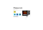


![Delibera n. 1566 del 24 dicembre 2014, [file]](http://vs1.manualzilla.com/store/data/006104494_1-a7f15ed5560a6af2ac4d03a3c6319b1c-150x150.png)