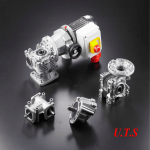
1
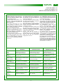
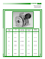
VS
V ARI ATORI DI VELOCITA’ A S ATELLITI
PL ANET ARY SPEED V ARIATORS
PL ANETENVERSTELLGETRIEBE
MVS - Variatore
con motore IEC
FVS - Variatore
con flangia entrata IEC
• Potenze da 0.22 a 4.0
kW
• Campo di variazione
continuo 5÷1
• Coppie uscita da 1.5 a
64 Nm
C-MVS it gb de Ed01 2007
MVS - Speed variator
with IEC motor
FVS - Speed variator
with IEC input
• Powers 0.22 to 4.0 kW
• Stepless speed range
5÷1
• Output torques 1.5 to
64 Nm
MVS - Verstellgetriebe
mit IEC Motoren
FVS - Verstellgetriebe
mit IEC Motorflansch
• Leistungen von 0.22
bis 4.0 kW
• Stufenlos Bereich 5÷1
• Ausgangsdrehmoment
von1.5 bis 64 Nm
VARVEL
VS
VARIATORI SERIE “VS”
VARIATORS SERIES “VS“
VERSTELLGETRIEBE BAUREIHE “VS“
VS - Variatore di velocità meccanico
VS - Mechanical speed variator
VS - Verstellgetriebe
I variatori della serie VS sono costruiti con
carcassa e coperchi in alluminio pressofuso fino alla grandezza VS080 e in ghisa
per le grandezze superiori.
The variators Series VS are manufactured
with housing and covers of pressure die
cast aluminium up to the size VS080 and
cast iron for bigger units.
Die Verstellgetriebe der Serie VS haben
bis zur Baugröße VS080 Gehäuse und
Deckel aus Aluminium-Druckguß und aus
Guß bei Baugröße VS090.
Le coppie indicate nelle tabelle di selezione sono coppie di uscita relative alla
grandezza considerata e le potenze sono
riferite a 1440 min-1.
The torques as shown in selection tables,
are output torques referred to the specific
size and powers to 1440 rpm.
Die in den Auswahltabellen genannten
Drehmomente sind jeweils die Ausgangsdrehmomente der entsprechenden Baugröße, und die Leistungen beziehen sich
auf eine Nenndrehzahl von 1440 min-1.
Sono possibili gli azionamenti con motori
a 2 poli o motori c.c. a 3000 min-1: in tal
caso i variatori saranno forniti con tappo di
sfiato a corredo, da apporre a cura del
cliente nel foro filettato più elevato.
I variatori sono spediti già riempiti con lubrificante fino alla grandezza 80 e con lubrificante a corredo per le grandezze superiori, nelle quantità per le posizioni di
funzionamento indicate a pag. 6.
I valori delle tabelle di selezione sono intesi per fattore di servizio FS1.0, vale a
dire con funzionamento di 8-10 ore al
giorno, con carico uniforme, avviamenti
inferiori a 6 all’ora e temperatura ambiente
fra 15 e 35 °C.
Vent plugs to fit on the highest position
after the installation, allow free-trouble
operation with 2-pole standard ac motors,
or 3000 rpm dc motors.
The variators are delivered already filled
with lubricant up to the size 80 and with
lubricant in a separate kit for bigger sizes,
in the right oil quantity for the mounting
positions as shown at page 6.
Die Verstellgetriebe werden mit einer
separat Verschlussschraube geliefert
sein, und auf höher Gewindebohrung
montieren werden, und es ist möglich einen problemlosen Einsatz von 2-poligen
Motoren oder Gleichstrommotoren bis
3000 min-1 im Dauerbetrieb.
Selection table data are intended for
service factor 1.0, i.e. 8-10 running hours
per day, uniform load, les than 6 start/
stops per hour and room temperature
ranging from 15 to 35 °C.
Die Getriebe werden mit Schmiermittelfüllung bis der Größe 80 ausgeliefert und
mit Schmiermittel zu Ausstattung für die
Höhere Größe, in Mengen für die Montagepositionen auf Seite 6 angegeben.
Die Tabellenwerte berücksichtigen einen
Betriebsfaktor von FS 1.0, d.h. Betrieb 810 Stunden/Tag, gleichmäßige Belastung,
weniger als 6 Schaltvorgängen (Start und
Halt) je Stunde und Umgebungstemperaturen zwischen 15 und 35 °C .
SPECIFICHE
GENERALI
GENERAL
SPECIFICATIONS
Gamma
Range
Bereich
6 grandezze
Regolazione continua 1:5
64 Nm coppia uscita max
6 sizes
Stepless variation range 5÷1
64 Nm max. output torque
6 Baugrößen
Stufenlos Bereich 5÷1
64 Nm max. Abtriebsmoment
Dimensionamento
Sizing
Auslegung
Vita media 15.000 ore con fattore
di servizio SF1
15,000 hrs average lifetime with
service factor SF1
15T Stunden Lebensdauer für
Verzahnung und Lagerung bei
einem Bfaktor SF1
Carcassa, Coperchi
Housing, Covers
Gehäuse, Flansche
Pressofusione in alluminio
AlSi12Cu2Fe fino VS080 e ghisa
G25 da VS090
Pressure die cast aluminium
AlSi12Cu2Fe till size VS080 and
cast iron from VS090
Aluminium-Druckguss
AlSi12Cu2Fe bis Größe VS080
und G25 bei VS090
Alberi & Linguette
Shafts & Keys
Wellen u. Passfedern
Alberi h7 - Fori E8
Linguette secondo DIN6885 B1
Shafts h7 - Bores E8
Keys according to DIN6885 B1
Wellen h7 - Bohrungen E8
Passfedern nach DIN6885 B1
Cuscinetti
Bearings
Lagerung
Cuscinetti a sfere secondo
grandezza e specifiche tecniche
Ball bearings according to sizes
and technical requirements
Kugellager entsprechend den
technischen Vorschriften
Paraolio
Oil seals
Dichtungen
Tipo NB - nitril-butadiene
con secondo labbro parapolvere
secondo DIN 3760
Type NB - nitril-butadiene
with additional anti-dust lip
according to DIN 3760
Typ NB - Nitril-Butadien
mit zusätzlicher Staublippe
entsprechend DIN 3760
Lubrificante
Lubricant
Schmierung
Fluido per trasmissioni automatiche
Automatic transmission fluid
(ATF) Automatik-Getriebeöl
Verniciatura
Painting
Lackierung
Vernice: a spruzzo o a polveri
epossidiche, RAL9006
Coating: spray or epoxy-powder
paint, RAL9006
Nasslackierung- oder Epoxydpulverfarbe RAL9006
- 2 -
ALLGEMEINE
EIGENSCHAFTEN
VARVEL
VS
PRINCIPIO DI FUNZIONAMENTO
WORKING PRINCIPLE
FUNKTIONSPRINZIP
La pista interna fissa 10 calettata sull'albero motore e la pista 11 pressata dalle
molle a tazza 12 trasmettono la rotazione
ai satelliti 7 i quali, traslando sulle due piste esterne 6 e 9, pongono in rotazione il
porta satelliti 2 (solidale all’albero di uscita) al quale sono collegati tramite le boccole scorrevoli 3.
The fixed inner race 10 fitted on motor
shaft and the mobile one 11 pressed by
the Belleville washers 12, transmit the rotation to planetary discs 7 that moving on
the two outer races 6 and 9, rotate accordingly the planetary disc holder 2 - one
piece with the output shaft - to which the
planetary discs are connected through the
sliding bushes 3.
The hand wheel controls the rotation of
the race 6 and its axial movement.
Such shifting is owed to the action of balls
5 on the two opposed cams 4 and 6, and it
acts on the cone sides moving them radially inside the races 10 and 11 winning
this way the reaction of the springs 12.
The variation of contact position on planetary discs originates the speed variation of
planetary disc holder and accordingly of
output shaft.
La regolazione della velocità non deve
mai essere effettuata a variatore fermo.
Never adjust the output speed when
the variator is at standstill.
Die innere, feste Laufbahn 10, die mit der
Motorwelle verbunden ist, und die Laufbahn 11, die von den Tellerfedern 12 gepresst wird, übertragen die Drehung an
den Satelitten 7 die dann auf den zwei
Aussenbahnen 6 und 9 laufen und den
Satelittenträger in Rotation zwingen, (dieser ist mit der Ausgangswelle fest verbunden) und die Satelliten sind am Satellitenträger mittels Gleitbuchsen befestigt.
Mit der Drehung des Steuerrades bewirkt
man die Rotation der Laufbahn 6 und
dessen axialen Verschiebung; diese Verschiebung wird von den Kugeln 5 auf der
Laufbahn der zwei gegenüberliegenden
Stuerkurven 4 und 6 ermöglicht und wirkt
auf die konischen Seitenflächen der Satelliten die sich entgegen der Federkraft 12
durchsetzten und radial hinein in den
Laufbahnen 10 und 11 bewegen. In dieser
Weise, beim Verstellen der Position der
Kontaktfläche auf der Satellitenseite, wird
die Geschwindigkeit des Satellitenträger
und somit der Ausgangswelle bestimmt.
I riferimenti delle parti interne utilizzati
nella descrizione del principio di funzionamento sono elencati a pagina 10.
Items of internal parts used in working
principle description are listed at page 10.
Die Geschwindigkeitverstellung darf
nie bei stehendem Verstellgetriebe erfolgen.
Ruotando il volantino di comando si ha la
rotazione della pista 6 con relativo spostamento assiale della stessa; tale spostamento è dovuto all'azione delle sfere 5
sulle piste delle due camme contrapposte
4 e 6 ed agisce sui fianchi conici dei satelliti, i quali si spostano radialmente all'interno delle piste 10 e 11, vincendo la reazione delle molle 12. In questo modo, al
variare della posizione del contatto sui
fianchi dei satelliti, si determina la variazione della velocità del porta satelliti e
quindi dell'albero uscita.
Die Bezeichnung der Teile, wie im Funktionsprizip beschrieben, sind auf Seite 10
dargestellt.
Velocità minima
Minimum Speed
min. Geschwindigkeit
Motori elettrici
I motori elettrici sono forniti con voltaggio
trifase 230/400V (±10%) e monofase
230V, frequenza 50Hz, 4 poli, classe di
isolamento F con temperatura ambiente di
40°C, grado di protezione IP 55.
A richiesta, motori con caratteristiche diverse, monofasi ad alta coppia di spunto,
autofrenanti, a doppia polarità.
La morsettiera è posta come standard dal
lato volantino di comando (v. pag. 4).
Velocità massima
Maximum Speed
max. Geschwindigkeit
Electric motors
The electric motors are supplied with voltage 230/400V (±10%) three-phase and
230V single-phase, frequency 50 Hz, 4
poles, temperature class F at ambient
temperature 40 Celsius, protection IP55.
On request, motors according to different
specifications, high starting torque singlephase, brake-motors, dual-speed motors.
The terminal box is located as standard on
the same hand wheel side (see page 4).
- 3 -
Elektromotoren
Als Elektromotoren kommen Dreiphasenmotoren mit 230/400 V (+/- 10%) und Einphasenmotoren mit 230 V, 50 Hz, 4-polig,
Isolationsklasse F bei 40°C Umgebungstemperatur in Schutzart IP 55 zum Einsatz. Auf Anfrage sind auch Motoren in
Sonderausführungen lieferbar, ebenso wie
Bremsmotoren, Einphasenmotoren mit hohem Anlaufmoment, polumschaltbare Motoren. Als Standard befindet sich der
Klemmkasten auf der selben Seite des
Steuerrades (siehe Seite 4).
VS
VARVEL
DESIGNAZIONE
DESIGNATION
BEZEICHNUNG
DESIGNAZIONE DEL VARIATORE
F VS
080 B5
IEC71 B5
VARIATOR DESIGNATION
BEZEICHNUNG VARIATOR
Opzioni/Options/Optionen
IG = Indicatore gravitazionale 0-20, Gravity reading handwheel 0-20,
Gravitationsmesser 0-20
B5 = Forma motore (solo B5) - Motor form (only B5) - Motorbauform (nur B5)
Grandezza motore elettrico - Electric motor frame - Motorbaugroße
B3, B5, V1, V3 = Forma costruttiva - Mounting form - Montageposition
063, 070, 080, 090, 100, 112 = Grandezza variatore VS - Gearbox size VS - Baugröße VS
VS = Tipo variatore - Gearbox type - Getriebetyp.
M
F
= Motovariatore
= Flangia entrata IEC
- Motorized unit
- IEC input flange
DESIGNAZIONE DEL MOTORE
MT
0.37kW 71B
4
B5
- Variator mit Motor
- Eingangsflansch IEC
MOTOR DESIGNATION
230/400/50
BEZEICHNUNG MOTOR
IP55 F X4
Posizione morsettiera - Terminal box position - Klemmenkastenlage
Cl. F (std) = Classe isolamento - Insulation class - Isolationsklasse
IP55 (std) = Grado protezione - Protection class - Schutzart
Tensione/frequenza - Voltage/frequency - Spannung/Frequenz
Forma costruttiva (solo B5) - Mounting (B5 only) - Bauform (nur B5)
Numero poli - Pole number - Polzahl
X3
Grandezza IEC motore - IEC motor size - Baugröße Motor
X4
Potenza motore - Motor power - Leistung Motor
MT = Motore trifase
- Three-phase motor
MM = Motore monofase
- Single-phase motor
MA = Motore autofrenante - Brake motor
X2
(std)
- Dreiphasen-Motor
- Einphasen-Motor
- Bremsmotor
OPZIONI
OPTIONS
L’allestimento standard, ove non diversa- Standard fitting side, unless otherwise remente richiesto, è montato sul lato sinistro quested, is the left side of the gearbox
visto dall’entrata.
when seen from the input side.
- 4 -
X1
OPTIONEN
Die Standardausführung, wenn nicht gesondert angefragt, wird auf die linke Seite,
vom Eingang her betrachtet, montiert.
VARVEL
VS
POSIZIONI DI MONTAGGIO
STANDARD MOUNTING POSITIONS
MONTAGEPOSITION
MVS
FVS
Uscita
Output
Ausgang
B5
Volantino di comando
Control hand wheel
Steuerrad
V1
SX (std)
DX (opt)
Volantino standard
Standard hand wheel
Standard Handrad
11
12
13
21
22
23
Volantino gravitazionale
Gravity hand wheel
Gravitationshandrad
31
41
- 5 -
V3
VARVEL
VS
TABELLA SELEZIONE
SELECTION TABLE
AUSWAHLTABELLE
Potenza
Power
Leistung
[kW]
Tipo
Type
Typ
Velocità uscita
Output speed
Geschwindigkeit
[min -1 - rpm]
Coppia uscita
Output torque
Drehmoment
[Nm]
Rendimento
Efficiency
Wirkungsgrad
0.22
MVS063
170 ÷ 880
3.8 ÷ 1.9
0.31 ÷ 0.80
0.37
MVS071
200 ÷ 1000
6÷3
0.34 ÷ 0.85
0.55
0.75
MVS080
MVS080
200 ÷ 1000
200 ÷ 1000
9 ÷ 4,5
12 ÷ 6
0.34 ÷ 0.84
0.34 ÷ 0.84
1.1
1.5
MVS090
MVS090
200 ÷ 1000
200 ÷ 1000
18 ÷ 9
24 ÷ 12
0.34 ÷ 0.86
0.34 ÷ 0.86
2.2
MVS100
200 ÷ 1000
36 ÷ 18
0.34 ÷ 0.86
3.0
4.0
MVS112
MVS112
200 ÷ 1000
200 ÷ 1000
48 ÷ 24
64 ÷ 32
0.34 ÷ 0.86
0.34 ÷ 0.84
- 6 -
VS
VARVEL
DIMENSIONI DI INGOMBRO
OVERALL DIMENSIONS
ABMESSUNGEN
MVS B5
VS
063
071
080
090
100
112
B
23
30
40
50
60
60
D ( h7 )
11
14
19
24
28
28
E
50
40
58
----
---
---
G
112.5
110
139
188
208
208
G3
64.5
74
85.5
115
131
131
H
70
80
100
126
150
150
I
72
90
98
241
270
270
M
115
130
165
165
215
215
M1
60
77
84
---
---
---
N
95
110
130
130
180
180
O
9
9
11
11
15
15
D1
M6
M8
M8
---
---
---
P
140
160
200
200
250
250
T
3.5
3.5
3.5
3.5
4
4
K
46
53
60
---
---
---
VC
71
71
79
---
---
---
VF
111
123
140
144
188
188
VL
78
90
107
122
150
150
VR
110
110
120
150
160
160
VR1
110
110
120
---
---
---
VS
85
85
110
110
110
110
b
4
5
6
8
8
8
f
M5
M6
M6
M8
M10
M10
t
12.5
16
21.5
27
33
33
X
200
227
268
290
320
340
Y
120
141
160
195
215
240
Dimensioni motore: vedi pag. 9
Dimensioni non impegnative
- Motor dimensions: see page 9
- Not binding dimensions
- 7 -
- Abmessungen Motor: siehe Seite 9
- unverbindliche Abmessungen
VARVEL
DIMENSIONI DI INGOMBRO
OVERALL DIMENSIONS
ABMESSUNGEN
MVS B3
VS063
VS071
VS080
A
121
124
150
B
147
149
190
C
105
105
125
D
110
120
160
E
6.5
7.5
11
H
76.5
94
111
Dimensioni non impegnative
VS
- Not binding dimensions
- 8 -
- unverbindliche Abmessungen
VARVEL
DIMENSIONI DI INGOMBRO
OVERALL DIMENSIONS
ABMESSUNGEN
MOTORI ELETTRICI
ELECTRIC MOTORS
ELEKTROMOTOREN
IEC MOTOR
B5
63
71
80
90 S / L
D1 ( j6 )
11
14
19
24
28
F2
9
9
11
11
14
G2 ( j6 )
95
110
130
130
180
M3
12.8
16.3
21.8
27.3
31.3
N3
4
5
6
8
8
R2
115
130
165
165
215
X
123
140
159
176
195 / 219
Y
185
215
238
Y2
140
160
200
200
250
Z1
110
121
138
149
160 / 172
Dimensioni non impegnative
VS
- Not binding dimensions
- 9 -
100 - 112
255 / 280
- Durchmesser auf Anfrage
309 / 328
VARVEL
VS
ELENCO PARTI
PART LIST
EINZELTEILE
VS 063 - 112
1
Albero di uscita
1
Output shaft
1
Ausgangswelle
2
Porta satelliti
2
Planetary disc holder
2
Satellitenträger
3
Boccola scorrevole
3
Sliding bush
3
Schiebebuchse
4
Pista di regolazione
4
Adjusting cam
4
Steuerkurve
5
Anello porta sfere
5
Ball set
5
Kugelträgerring
6
Pista mobile esterna
6
External cam
6
Aussenbahn
7
Satellite
7
Planetary disc
7
Satellit
8
Scatola di comando
8
Control box
8
Steuergehäuse
9
Pista fissa esterna
9
External fixed race
9
Drehfeste Aussenbahn
10
Pista fissa interna
10
Internal fixed race
10
Drehfeste Innenbahn
11
Pista mobile interna
11
Internal mobile race
11
Drehende innere Laufbahn
12
Molle a tazza
12
Belville washer
12
Tellerfeder
- 10 -
VARVEL
VS
SELEZIONI VARIATORE CON RIDUTTORE
VARIATOR AND SPEED REDUCER SELECTIONS
AUSWAHL REGELGETRIEBE
FRS
FVS
FRT
FRD
Richiedere i cataloghi specifici per la
selezione dei rapporti di riduzione e delle
coppie di uscita per gli accoppiamenti dei
possibili gruppi motore-variatore-riduttore:
Ask for appropriate gearbox catalogue to
select the reduction ratios and output
torques for the feasible combinations of
the following units motor-variator-gearbox:
Verlangen Sie den Katalog für die
Bestimmung des Übersetzungen für die
Verbindung des möglichste Gruppen
Motor-Verstellgetriebe-Getriebe:
• MVR / FRS
• MVR / FRS
• MVR / FRS
• MVS / FRT
• MVS / FRT
• MVS / FRT
• MVS / FRD
• MVS / FRD
• MVS / FRD
- 11 -
VARVEL
VS
Estratto delle ISTRUZIONI D’USO E MANUTENZIONE
Abstract of OPERATION AND MAINTENANCE INSTRUCTIONS
Zusammenfassung der BETRIEBS- UND WARTUNGSANWEISUNGEN
I riduttori e i variatori di velocità non ricadono nel
campo d’applicazione della Direttiva Macchine,
art.1(2) e non possono essere messi in servizio
finché la macchina nella quale devono essere
incorporati, sia stata dichiarata conforme all’art.
4(2), all. II(B) delle Direttive Macchine
98/37/CEE/22.6.98 e, solo per l’Italia, al DL
459/24.7.96.
Variable speed and reduction gearboxes are not
part of the field of application of the Machinery
Directive, art.1(2), and they must not be put into
service until the machinery into which they are
to be incorporated, has been declared in conformity with the provision of art.4(2), annex II(B) of
Machinery Directives 98/37/CEE/22.6.98 and for
Italy only, of DL 459/24.7.96.
Varvel-Getriebe und Variatoren fallen nicht unter
den Geltungsbereich der Maschinenrichtlinien,
Artikel 1 (2): Sie dürfen jedoch nicht in Betrieb
gesetzt werden, bevor sich nicht Maschinen, in
die sie eingebaut werden, mit Artikel 4 (2), Anhang II (B) der Maschinenrichtlinien 98/37/
CEE/22.6.98, und (nur für Italien) DL 459/
24.07.96, in Übereinstimmung befinden.
Installazione
Accertarsi che il gruppo da installare abbia le
caratteristiche atte a svolgere la funzione richiesta e che la posizione di montaggio sia coerente
con quanto ordinato. Tali caratteristiche sono
deducibili dalla targhetta d’identificazione apposta sul riduttore. Effettuare la verifica della stabilità del montaggio affinché non si verifichino vibrazioni o sovraccarichi durante il funzionamento.
Installation
Check if the unit to be installed, is properly selected to perform the required function and that
its mounting position complies with the order.
The nameplate reports such information.
Check mounting stability to run the unit without
vibrations or overloads.
Aufstellung
Vor der Aufstellung ist zu prüfen, dass die Antriebseinheit in bezug auf die Betriebsbedingungen richtig ausgewählt wurde und die Einbaulage
mit der Bestellung
übereinstimmt. Angaben
hierüber sind auf dem Typenschild zu finden. Die
Stützkonstruktion für die Getriebe ist so stabil
auszuführen, dass keine Schwingungen oder
Überlastungen auftreten, eventuell sind elastische Kupplungen oder Drehmomentbegrenzer
zu verwenden.
Inbetriebnahme
Die Antriebseinheit kann in beiden Drehrichtungen eingesetzt werden. Die Einheit müsst sofort
angehalten werden, wenn ein unzulässiger Lauf
oder unerwartete Geräusche auftreten.
Das fehlerhafte Teil ist zu ersetzen oder die Einheit ist zur Überprüfung einzuschicken. Falls das
fehlerhafte Teil nicht ersetzt wird, kann dies zu
weiteren Schäden an anderen Bauteilen führen,
was eine Feststellung der Ursachen sehr schwierig machen kann.
Funzionamento
Il riduttore può essere collegato per rotazione
oraria o antioraria. Arrestare immediatamente il
riduttore in caso di funzionamento difettoso o di
rumorosità anomala, rimuovere il difetto o ritornare l’apparecchio alla fabbrica per un’adeguata
revisione. Se la parte difettosa non è sostituita,
anche altri componenti possono essere danneggiati con conseguenti ulteriori danneggiamenti e più scarsa possibilità di risalire alle
cause.
Manutenzione
Sebbene i gruppi siano provati con funzionamento senza carico prima della spedizione, è
consigliabile non usarli a carico massimo durante le prime 20-30 ore di funzionamento
affinché le parti interne possano adattarsi
reciprocamente. I riduttori sono spediti già
riempiti con olio sintetico a lunga durata e, se
occorre sostituire o rabboccare il lubrificante,
non mescolare oli a base sintetica con oli a base
minerale.
Movimentazione
In caso di sollevamenti con paranco, utilizzare
posizioni di aggancio sulla struttura della carcassa, golfari ove esistenti, fori dei piedi o sulle
flange, evitando tutte le parti mobili.
Verniciatura
Qualora il gruppo subisca una verniciatura successiva, è necessario proteggere accuratamente gli anelli di tenuta, i piani di accoppiamento e gli alberi sporgenti.
Conservazione prolungata a magazzino
Per permanenze maggiori di tre mesi, è consigliata l’applicazione di antiossidanti su alberi
esterni e piani lavorati, e di grasso protettivo sui
labbri dei paraolio.
Gestione Ambientale del prodotto
In conformità alla Certificazione Ambientale ISO
14001, sono suggerite le seguenti indicazioni
per lo smaltimento del nostro prodotto:
- i componenti del gruppo che vengono rottamati
debbono essere consegnati a centri di raccolta autorizzati per i materiali metallici;
gli oli ed i lubrificanti raccolti dal gruppo devono
essere smaltiti consegnandoli ai Consorzi Oli
esausti;
- gli imballi a corredo dei gruppi (pallet, cartone,
carta, plastica, ecc.) vanno avviati per quanto
più possibile al recupero/riciclo, consegnandoli a
ditte autorizzate per le singole classi di rifiuto.
Running
The unit may be connected for clockwise or
counter-clockwise rotation.
The unit must be stopped as soon as defective
running or unexpected noise occur, remove the
faulty part or return the unit to the factory for
checking.
If the faulty part is not replaced, other parts can
also be affected, causing more severe damage
and making the identification of initial cause
more difficult.
Maintenance
Although the units are no-load run tested in the
factory before despatch, it is recommended not
to run them at maximum load for the first 20-30
running hours to allow the proper running in.
The gearboxes are delivered already filled with
long-life synthetic oil and, in case of replacement or topping, do not mix with mineral lubricants.
Handling
When hoisting, use relevant housing locations or
eyebolts if provided, or foot or flange holes
Never hoist on any moving part.
Painting
Carefully protect oil seals, coupling faces and
shafts when units are re-painted.
Long-term storage
For storages longer than 3 months, apply antioxidants onto shafts and machined surfaces,
and protective grease on oil seal lips.
Product’s Environmental Management
In conformity with Environmental Certification
ISO 14001, we recommend the following to dispose of our products:
- scraped components of the units to deliver to
authorized centres for metal object collection;
oils and lubricants drained from the units to deliver to Exhausted Oil Unions;
- packages (pallets, carton boxes, paper, plastic,
etc.) to lead into regeneration/recycling circuits
as far as possible, by delivering separate waste
classes to authorized companies.
- 12 -
Wartung
Obwohl die Einheiten vor der Auslieferung im
Leerlauf getestet wurden, ist es ratsam sie in den
ersten 20-30 Stunden nicht mit Vorlast zu betreiben, um ein einwandfreies Einlaufen zu gewährleisten. Die Einheiten werden entsprechend den
Angaben auf dem Typenschild mit synthetischem Schmierstoff Lebensdauer geschmiert
ausgeliefert. Bei einem eventuellen Ölwechsel
oder Nachfüllen darf der Schmierstoff nicht mit
Mineralöl vermischt werden.
Handhabung und Transport
Beim Heben und Transport ist auf standsichere
Lage und sorgfältige Befestigung geeigneter Hebevorrichtungen zu achten. Bewegliche Teile
dürfen nicht zum Anheben benutzt werden.
Anstrich
Beim Erneuern oder dem zusätzlichen Aufbringen eines Anstriches sind die Dichtungen,
Kupplungssitze und Wellen sorgfältig zu schützen.
Langzeitlagerung
Die Einlagerung der Einheiten muss trocken und
staubfrei erfolgen. Bei einer Einlagerungszeit
über 3 Monate sind bearbeitete Flächen und
Wellen mit Rostschutzmitteln zu besprühen,
Dichtlippen sind mit Fett zu schützen.
Entsorgung
In Übereinstimmung mit ISO 14001 weisen wir
darauf hin, im Falle des Verschrottens die einzelnen Metallteile getrennt zu behandeln und
Schmiermittel bei den befugten Stellen zu entsorgen.
Verpackungen sollten soweit wie möglich wieder
verwendet werden.