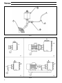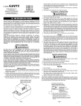
1
J-ATEX JP JS JX JX Pompe centrifughe autoadescanti Self-priming centrifugal pumps Pompes centrifuges autoamorçantes Selbstansaugende Kreiselpumpen Bombas centrífugas autocebantes Zelfaanzuigende centrifugaalpompen IT EN FR DE ES NL Istruzioni di sicurezza in accordo alla direttiva 94/9/CE 4 Safety instructions according to 94/9/EC Directive 13 Instructions de sécurité selon la Directive 94/9/CE 22 Sicherheitsanweisungen nach EG-Richtlinie 94/9/EG 31 Instrucciones de seguridad con arreglo a la Directiva 94/9/CE 40 Veiligheidsvoorschriften volgens de richtlijn 94/9/EG 49 Ed. 2011/01 - Rev. 02 - Cod. 506 2 1 3 4 Fig. 1 Fig. 2 2 Fig. 3 Fig. 4 3 IT - Istruzioni di sicurezza in accordo alla direttiva 94/9/CE - Pompe centrifughe autoadescanti LEGENDA FIGURE Fig. 1 Fig. 2 Figg. 3 e 4 Figg. 5, 6 e 7 ISTRUZIONI ORIGINALI Schema del circuito di lubrificazione della tenuta e dell’applicazione dell’elemento termosensibile: 1) Portatenuta - 2) Serbatoio liquido lubrificante - 3) Cavo compensato - 4) Termocoppia (tipo J)........ 2 Punti per la messa a terra...................................................................................................................... 2 Diagrammi esemplificativi per taratura dispositivo di sicurezza di massima pressione......................... 3 Schemi di identificazione prodotto . ....................................................................................................... 10, 11, 12 INDICE 1 PREMESSA . ................................................................................................................................................. 4 2 LUOGO DI INSTALLAZIONE ........................................................................................................................ 4 3 MARCATURA E INFORMAZIONI GENERALI .............................................................................................. 4 4 INSTALLAZIONE E AVVIAMENTO ............................................................................................................... 5 5 PULIZIA DELLA POMPA ............................................................................................................................... 6 6 CLASSE DI TEMPERATURA E DISPOSITIVO DI LIMITAZIONE DELLA TEMPERATURA.......................... 6 7 COLLEGAMENTO DI MESSA A TERRA . ..................................................................................................... 7 8 TENUTA MECCANICA................................................................................................................................... 7 9 DISPOSITIVO DI SICUREZZA ALLA MANDATA DELL’IMPIANTO .............................................................. 7 10 COMPATIBILITÀ TRA LIQUIDO PROCESSATO E MATERIALI DELLA POMPA ......................................... 11 LUBRIFICAZIONE CUSCINETTI................................................................................................................... 9 12 FISSAGGIO DEI COMPONENTI AL BASAMENTO...................................................................................... 9 13 CAVITAZIONE .............................................................................................................................................. 9 1. PREMESSA Le istruzioni di sicurezza contenute nel presente manuale integrano e sostituiscono, ove in conflitto, quelle contenute nel manuale “Istruzioni d’uso e manutenzione - pompe centrifughe autoadescanti - J”. Le istruzioni di sicurezza si riferiscono all’installazione, l’uso e la manutenzione di pompe centrifughe protette contro il rischio di esplosione e destinate all’utilizzo in aree con presenza di atmosfere potenzialmente esplosive. ATTENZIONE. Le presenti istruzioni sono indispensabili per la rispondenza della pompa ai requisiti della direttiva 94/9/CE pertanto devono essere: conosciute, disponibili, comprese ed utilizzate. ATTENZIONE. Il personale addetto all’installazione, all’ispezione ed alla manutenzione della pompa deve avere adeguata preparazione tecnica unita a cognizioni adeguate in materia di atmosfera potenzialmente esplosiva e rischi ad essa connessi. ATTENZIONE. Ogni utilizzo della pompa che non rispetti quanto scritto nelle Istruzioni d’uso e manutenzione e nella presente integrazione fa decadere i requisisti di sicurezza e di tutela dal pericolo di esplosione. ATTENZIONE. Sono stati analizzati i rischi connessi all’utilizzo della pompa nelle precise condizioni prescritte dal manuale d’uso e manutenzione e dalla presente integrazione: l’analisi dei rischi legati all’interfaccia con altri componenti dell’impianto è demandata all’installatore. 2. LUOGO DI INSTALLAZIONE I requisiti essenziali di sicurezza contro il rischio di esplosione nelle aree classificate sono trattati dalle direttive 94/9/CE e 1999/92/CE. 3. MARCATURA E INFORMAZIONI GENERALI Le pompe della gamma JP, in accordo alla direttiva 94/9/CE, riportano la seguente marcatura identificativa: 4 IT - Istruzioni di sicurezza in accordo alla direttiva 94/9/CE - Pompe centrifughe autoadescanti Le pompe della gamma JS, in accordo alla direttiva 94/9/CE, riportano la seguente marcatura identificativa: La marcatura applicata alle elettropompe della gamma JX, in accordo alla direttiva 94/9/CE, non è determinabile a priori in quanto è funzione del motore elettrico assemblato. Il significato delle sigle riportate nella marcatura è il seguente: II 2/2 G apparecchiatura appartenente al gruppo II, di categoria 2, destinata ad essere installata in zone in cui è probabile che un’atmosfera esplosiva, costituita da una miscela di aria e sostanze infiammabili sotto forma di gas, vapore o nebbia, si presenti occasionalmente durante il funzionamento normale (EN 1127-1 par. 6.3) nella zona esterna ed interna della pompa; c/b apparecchiatura con modalità di protezione contro l’accensione per sicurezza costruttiva (c) e per controllo della sorgente d’accensione (b) (EN 13463-5); IIB gruppo di esplosione dei gas; T4 classe di temperatura ammessa. L’utilizzatore deve processare fluidi in temperatura conformemente a tale classificazione tenendo in considerazione le indicazioni del presente manuale e le disposizioni normative vigenti. L’utilizzatore deve inoltre tenere in considerazione le temperature di innesco dei gas, vapori o nebbie presenti nella zona di impiego; X significa che ci sono condizioni particolari riguardanti la classe di temperatura da leggere nel presente manuale; II 2 D apparecchiatura appartenente al gruppo II, di categoria 2, destinata ad essere installata in zone in cui è probabile che un’atmosfera esplosiva, sotto forma di una nube di polveri combustibili nell’aria, si presenti occasionalmente durante il funzionamento normale (EN 1127-1 par. 6.3) nella zona esterna della pompa; Td apparecchiatura protetta contro la penetrazione della polvere; A21 apparecchiatura idonea secondo il metodo A, per zona 21 o zona 22 con polveri conduttrici; IP6X grado di protezione meccanica dell’apparecchiatura; T125 °C massima temperatura superficiale dell’apparecchiatura; simbolo di sicurezza di protezione dalle esplosioni, in riferimento alla direttiva 94/9/CE; simbolo di conformità alle direttive europee applicabili. 4. INSTALLAZIONE E AVVIAMENTO Montaggio del motore elettrico (gamma JP) Le pompe della gamma JP devono essere assemblate ad un motore elettrico conforme alla norma internazionale IEC 60034-7 e nel rispetto delle caratteristiche riportate nella Tabella 1. Tab. 1 - Caratteristiche dei motori elettrici da accoppiare alle pompe della gamma JP Modello JP 1-110 JP 1-180 JP 2-100 JP 2-120 JP 2-170 JP 2-180 JP 2-215 JP 2-200 JP 3-100 JP 3-140 JP 3-180 JP 3-210 Forma costruttiva / grandezza motore IM B34/80B IM B34/112 IM B34/80B IM B34/90L IM B34/112 IM B35/132S IM B35/132M IM B35/132S IM B34/90L IM B34/112 IM B35/132S IM B35/112 Potenza N* poli [kW] 1,1 4 1,1 2,2 4 5,5 11 7,5 2,2 4 7,5 4 2 2 2 2 2 2 2 2 2 2 2 4 Frequenza [Hz] 50 50 50 50 50 50 50 50 50 50 50 50 (segue) 5 IT - Istruzioni di sicurezza in accordo alla direttiva 94/9/CE - Pompe centrifughe autoadescanti Modello JP 3-230 JP 3-240 JP 3-252 JP 4-100 JP 4-159 JP 4-160 JP 4-220 JP 4-225 JP 4-250 JP 4-253 JP 6-250 JP 6-253 Forma costruttiva / grandezza motore IM B35/160M IM B35/160L IM B35/180M IM B34/112 IM B35/160M IM B35/160M IM B35/132S IM B35/180M IM B35/132M IM B35/132M IM B35/160M IM B35/160M Potenza N° poli [kW] 15 2 18,5 2 22 2 4 2 15 2 11 2 5,5 4 22 2 7,5 4 7,5 4 11 4 11 4 Frequenza [Hz] 50 50 50 50 50 50 50 50 50 50 50 50 Prima di mettere in funzione la pompa, si raccomanda di seguire le seguenti precauzioni generali: - controllare la presenza di lubrificante nel bicchierino della tenuta meccanica; - controllare che il corpo-pompa sia pieno di liquido; - controllare che nel fluido trattato non vi siano o non vi possano essere parti solide di dimensioni elevate o comunque tali da procurare danni. Controllare che non vi sia acciaio ossidato e parti ferromagnetiche anche di piccole dimensioni; - controllare che non ci siano restrizioni all’ingresso e/o all’uscita della pompa per evitare fenomeni rispettivamente di cavitazione e sovraccarico del motore; - controllare che le tubazioni di collegamento siano sufficientemente resistenti e che non possano deformarsi quando collegate alla pompa; - se la pompa è rimasta inattiva per lunghi periodi è opportuno far circolare acqua pulita per alcuni minuti per evitare il rischio di incrostazioni; - controllare che il verso di rotazione sia quello giusto; - controllare la messa a terra dell’allestimento e verificare che tra i singoli componenti ci sia continuità elettrica con la terra. 5. PULIZIA DELLA POMPA ATTENZIONE Pulire la pompa esclusivamente con un panno umido onde evitare accumuli di cariche elettrostatiche e di polvere. Verificare periodicamente che non vi siano depositi di alcun genere all’interno della pompa ed in particolare nella zona delle parti statoriche. 6. CLASSE DI TEMPERATURA E DISPOSITIVO DI LIMITAZIONE DELLA TEMPERATURA Ad eccezione delle pompe fornite di dispositivo di limitazione della temperatura, la classe di temperatura varia in funzione della temperatura del fluido pompato; di seguito vengono indicate le condizioni operative. Variazione ammessa della temperatura ambiente: −20 °C < Tamb < 60 °C per le pompe/elettropompe fornite con dispositivo di limitazione della temperatura −20 °C < Tamb < 40 °C per le pompe/elettropompe prive di dispositivo di limitazione della temperatura Per le pompe/elettropompe prive di dispositivo di limitazione della temperatura il valore massimo ammesso per la temperatura del fluido pompato è riportato nella Tabella 2. Tabella 2 T3 T4 T5 Tamb ≤ 40 °C 85 °C ≤ Tfluido < 100 °C 50 °C ≤ Tfluido < 85 °C −20 °C ≤ Tfluido < 50 °C ATTENZIONE Si deve verificare la compatibilità termica tra fluido pompato e materiali della pompa: in particolare, per le pompe che impiegano parti in NBR la temperatura del liquido pompato non deve superare 90 °C. ATTENZIONE In considerazione del campo di variazione ammesso della temperatura ambiente, temperature del fluido diverse da quelle riportate nella Tabella 2 non consentono il rispetto della classe di temperatura di riferimento oltre che causare danni alla pompa. ATTENZIONE Ad esclusione delle pompe della gamma JP che sono già fornite di dispositivo di limitazione della temperatura, dove l’utilizzatore preveda il rischio di superamento dei limiti di temperatura previsti nella Tabella 2, è necessario installare nell’impianto (vedi Fig. 1) un dispositivo di protezione certificato in conformità alla direttiva 94/9/CE. In tutti i casi, il dispositivo di protezione deve impedire il raggiungimento delle seguenti temperature: 6 IT - Istruzioni di sicurezza in accordo alla direttiva 94/9/CE - Pompe centrifughe autoadescanti T = 190 °C per la classe di temperatura T3; T = 125 °C per la classe di temperatura T4; T = 90 °C per la classe di temperatura T5. In caso di installazione del dispositivo di sicurezza, tali indicazioni sulla classe di temperatura sostituiscono i valori indicati nella Tabella 2. ATTENZIONE Si deve verificare la compatibilità termica tra fluido pompato e materiali della pompa: in particolare, per le pompe che utilizzano parti in NBR la taratura del dispositivo di protezione deve impedire al liquido pompato di superare la temperatura di 90 °C. Per le pompe che impiegano parti in VITON® o TEFLON® valgono i valori di taratura sopracitati. Il dispositivo di limitazione della temperatura deve essere collegato al quadro elettrico di comando; il collegamento deve essere eseguito da personale specializzato e nel rispetto delle normative vigenti. Il dispositivo di limitazione della temperatura fornito da Varisco è una termocoppia di tipo J dotata di due cavi di sezione pari a 0,5 mm2. 7. COLLEGAMENTO DI MESSA A TERRA Per le pompe della gamma JP, il collegamento equipotenziale con il motore elettrico che verrà assemblato è garantito all’atto dell’assemblaggio del motore stesso, purché si abbia cura di pulire da qualsiasi impurità le superfici delle flange di accoppiamento. Per le pompe della gamma JS, l’installatore deve avere cura di prevedere un opportuno collegamento di messa a terra e/o equipotenziale delle masse. Per le pompe della gamma JX, il collegamento equipotenziale delle masse dell’apparecchiatura è garantito dal costruttore ed il collegamento della messa a terra deve essere effettuato seguendo le norme tecniche pertinenti e rispettando le istruzioni d’uso dei componenti. In tutti i casi, i cavi utilizzati per la messa a terra o per il circuito di protezione equipotenziale devono avere una sezione adeguata e le superfici di contatto delle connessioni devono essere pulite e protette dalla corrosione. Per i punti di messa a terra si faccia riferimento alla Fig. 2. ATTENZIONE Tutti i collegamenti elettrici, sulla pompa e sull’impianto, devono essere effettuati in conformità alle norme tecniche pertinenti in vigore. L’impianto elettrico deve essere eseguito da personale qualificato in conformità alle specifiche norme di legge vigenti. ATTENZIONE La pompa deve essere sempre messa a terra indipendentemente dal motore od altro organo ad essa collegato. La mancanza di messa a terra o non corretta messa a terra fa decadere i requisisti di sicurezza e di tutela dal pericolo di esplosione. Deve sempre esserci continuità elettrica tra la pompa e gli altri elementi connessi alla terra. 8. TENUTA MECCANICA È possibile che la tenuta si danneggi ed il liquido contenuto nella pompa fuoriesca; l’utilizzatore deve valutare tale evento e prendere le dovute precauzioni affinché il liquido non interagisca con l’ambiente esterno. ATTENZIONE Ispezionare la tenuta ad ogni intervento di manutenzione della pompa ed arrestarla immediatamente in caso di perdita. La tenuta che perde deve essere sostituita seguendo le istruzioni riportate nel manuale “Istruzioni d’uso e manutenzione” della pompa. Devono essere utilizzati ricambi originali Varisco. La tenuta meccanica deve essere lubrificata mediante un liquido - compatibile con il liquido pompato - che sarà contenuto nell’apposito serbatoio fornito con la pompa; si consiglia, in caso di compatibilità, di usare olio per motori SAE 15W-40. Tra il contenitore del liquido lubrificante ed il portatenuta è interposta una diramazione per il collegamento di un sensore di temperatura: la pompa è cioè predisposta per il rilevamento della temperatura della tenuta. È responsabilità dell’utilizzatore: - collegare l’elemento termosensibile, se necessario, ad uno strumento di misura della temperatura certificato in accordo alla direttiva 94/9/CE (lo strumento è escluso dalla fornitura Varisco); - controllare periodicamente che il serbatoio del liquido lubrificante sia sempre pieno ed effettuare, se necessario, i rabbocchi. In Fig. 1 è riportato uno schema del circuito di lubrificazione e dell’applicazione dell’elemento termosensibile. 9. DISPOSITIVO DI SICUREZZA ALLA MANDATA DELL’IMPIANTO È assolutamente indispensabile installare un dispositivo di limitazione della pressione in prossimità della mandata della pompa. Tale componente deve essere marcato CE in conformità alla direttiva 97/23/CE (PED) in categoria 4 come dispositivo di sicurezza, ed in conformità alle direttive 94/9/CE e nel rispetto delle prescrizioni della 99/92/CE. ATTENZIONE L’assenza o la non corrispondenza alle caratteristiche richieste del dispositivo di sicurezza di massima pressione fa decadere i requisiti di sicurezza e di tutela dal pericolo di esplosione della pompa. La pressione di intervento di tale dispositivo deve essere ricavata dalla curva di prestazione della pompa relativa alla velocità di rotazione impiegata, come indicato negli esempi seguenti. Esempio 1. Alla velocità di rotazione di 2900 rpm ed alla portata di 50 m3/h la pressione è di 48 m; il dispositivo di massima 7 IT - Istruzioni di sicurezza in accordo alla direttiva 94/9/CE - Pompe centrifughe autoadescanti pressione deve essere tarato affinché la pressione non superi 52 m che è il valore della pressione massima relativo al campo di funzionamento ottimale della pompa (tratto in linea grossa nella Figura 3). Esempio 2 (vedi Figura 4). Alla velocità di rotazione di 2900 rpm ed alla portata di 13 m3/h la pressione è di 54 m; il dispositivo di massima pressione deve essere tarato ad un valore tale che non si verifichi mai il funzionamento della pompa a portata nulla (quindi, nell’esempio considerato, ad un valore compreso fra 54 e 56 m). ATTENZIONE Una errata taratura del dispositivo di sicurezza di massima pressione fa decadere i requisisti di sicurezza e di tutela dal pericolo di esplosione della pompa. 10. COMPATIBILITÀ TRA LIQUIDO PROCESSATO E MATERIALI DELLA POMPA L’utilizzatore dovrà sempre pompare liquidi che siano compatibili con i materiali costruttivi della pompa. A tale proposito deve verificare la compatibilità chimica esistente tra il fluido di processo ed i materiali della pompa. Sono di facile reperibilità nella letteratura tecnica delle tabelle che forniscono il grado di compatibilità fra due materiali: da “non raccomandabile” (cioè alterazione delle caratteristiche di uno dei due materiali) a “ottima” (cioè non ci sono alterazioni significative delle caratteristiche di uno dei due materiali). Per conoscere i materiali di cui è costituita una pompa ci si avvale, contemporaneamente, delle Figg. 5, 6, 7 e delle Tabb. 3, 4, 5 e 6. Dalle Figg. 5, 6, 7 confrontandole con la targhetta applicata alla pompa, si determina le sigle rappresentative della metallurgia della pompa e dei materiali della tenuta. Dalla Tabella 3, con le sigle determinate precedentemente, si determina le sigle dei materiali dei vari componenti impiegati in una determinata esecuzione costruttiva. Infine, dalle Tabelle 4, 5 e 6 si ricava il significato di ogni sigla individuata al passo precedente. ATTENZIONE L’utilizzo della pompa con fluidi non compatibili con i materiali dei componenti di essa o in ambiente con presenza di fluidi non compatibili è vietato in ogni caso. Tabella 3 - Materiali dei componenti della pompa in funzione dell’esecuzione Esecuzione Corpo pompa Girante Piatto d’usura Albero Tipo G1 G G G S 1 F1 G K K K 1 P1 G G G S 1 Q1 G B B K 1 T1 G+QPQ G+QPQ G+QPQ S 1 S1* G S G S 1 R1* G+QPQ S G+QPQ S 1 B1 B B B K 1 K1 K K K K 1 L1 KL KL KL KL 1 A1AAA S 1 G2 G G G S 2 F2 G K K K 2 K2 K K K K 2 L2 KL KL KL KL 2 P3 G G G S 3 F4 G K K K 4 K4 K K K K 4 L4 KL KL KL KL 4 F5 G K K K 5 K5 K K K K 5 L5 KL KL KL KL 5 Tenuta Parte rotante Parte fissa YN YN YV YV YV YV YV YV YN YN YN YN YN YN YN YV YV YV YV YN YN WT WT WT WT WT WT WT WT GV YV YV YV YV YV YV YV YV YV YV YV YV YV * Il dente di innesco (inizio voluta) è in acciaio ed il piatto d’usura è parzialmente rivestito in NBR Tabella 4 - Legenda materiali pompa Sigla materiale pompa G G+QPQ A B K KL S Descrizione Ghisa (EN GJL-200 / EN GJS-400 / EN GJS-500 ) Ghisa con trattamento di nitrocarburazione TENIFER-QPQ® (Quench-Polishing-Quench) ** Alluminio AlSi4,5MnMg - UNI 3054 (Anticorodal) Bronzo UNI 85.5.5.5 (B10) Acciaio inox AISI 316 (CF8M per i componenti di fusione) Acciaio inox AISI 316L (CF3M per i componenti di fusione) Acciaio bonificato C40 (albero) Acciaio ASTM A 216 WCB (girante esecuzioni S ed R) ** Il trattamento di nitrocarburazione TENIFER-QPQ® viene effettuato su corpo, portamotore, girante e piatto d’usura. 8 IT - Istruzioni di sicurezza in accordo alla direttiva 94/9/CE - Pompe centrifughe autoadescanti Tabella 5 - Legenda materiali tenuta (parti striscianti) Sigla materiale tenuta Y W G S Descrizione Carburo di silicio sinterizzato (SiC) Carburo di tungsteno sinterizzato (WC) Grafite sintetica Steatite (ceramica silicea) Tabella 6 - Legenda materiali tenuta (elastomeri) Sigla materiale guarnizione N T V Descrizione Gomma nitrilica (NBR) PTFE - politetrafluoroetilene (TEFLON®) Gomma in fluoroelastomero (VITON®) L’elastomero con cui è fabbricata la valvola a clapet in aspirazione della pompa è lo stesso utilizzato nella tenuta meccanica. La guarnizioni piane tra il corpo pompa ed il portamotore sono in: - Centellen WS3820® se gli elastomeri della tenuta sono in TEFLON®; - Guamotor 33 G® in tutti gli altri casi. 11. LUBRIFICAZIONE CUSCINETTI Le pompe possono essere costruite con due tipi di cuscinetti: 1. cuscinetti schermati o stagni (del tipo 2RS o ZZ) che non richiedono ingrassaggio. Quindi, se utilizzati correttamente, non richiedono interventi di manutenzione durante il periodo di vita previsto per il cuscinetto. Per le pompe della gamma JP, che impiegano questo tipo di cuscinetti, è necessaria la sostituzione ogni 1500 ore di funzionamento circa; 2. cuscinetti che devono essere lubrificati ogni 500 ore di funzionamento con grasso al litio a base di olio minerale (HTF 5613 GRADO 3). ATTENZIONE Una scarsa o errata lubrificazione dei cuscinetti fa decadere i requisisti di sicurezza e di tutela dal pericolo di esplosione della pompa. La sostituzione dei cuscinetti deve essere fatta esclusivamente dalla Varisco S.p.A. o da personale tecnico competente (per la manutenzione e la sostituzione dei cuscinetti fare riferimento anche al manuale “Istruzioni d’uso e manutenzione” della pompa). 12. FISSAGGIO DEI COMPONENTI AL BASAMENTO Le pompe fornite già accoppiate ad un motore elettrico mediante giunti ed eventuali riduttori meccanici, sono già state sottoposte, in fase di montaggio in fabbrica, ad un allineamento ottimale tra i vari alberi di trasmissione del moto. Tuttavia, in fase di installazione sul luogo di lavoro della macchina, occorre ricontrollare l’allineamento nel seguente modo: - sistemare il basamento sul piano della soletta infilando i tirafondi nei fori del basamento senza però serrare i bulloni; - togliere i coprigiunti; - serrare i bulloni dei tirafondi e riverificare l’allineamento assiale, radiale e parallelo come indicato nei manuali dei singoli giunti. Se si dovessero riscontrare dei disallineamenti, riportarli entro i valori consentiti seguendo le istruzioni di montaggio dei giunti; - riposizionare i coprigiunti prima dell’avviamento. È inoltre essenziale verificare periodicamente la coppia di serraggio dei bulloni che fissano i singoli componenti al basamento (incluse la viti che bloccano il coprigiunto). 13. CAVITAZIONE La cavitazione, oltre ad essere dannosa per la pompa, è un fenomeno pericoloso in atmosfera potenzialmente esplosiva: occorre controllare che la pompa sia stata scelta correttamente facendo riferimento alle curve di NPSH richiesta dalla pompa. L’installatore deve effettuare il calcolo di NPSH disponibile nell’impianto (considerando quindi anche i filtri, le valvole e tutte le perdite fluidodinamiche in aspirazione). ATTENZIONE La Varisco S.p.A. declina ogni responsabilità per malfunzionamenti causati da NPSH disponibile non adeguata, limitandosi a fornire il valore di NPSH richiesta dalla pompa. 9 IT - Istruzioni di sicurezza in accordo alla direttiva 94/9/CE - Pompe centrifughe autoadescanti Esempio: JS 1-110 G10 Ex J S 1-110 G 1 0 Ex Ex: predisposizione per versione ATEX 0: versione senza flussaggio portamotore 1: versione con flussaggio portamotore 1: 2: 3: tipo di tenuta e materiali impiegati (vedi Tab. 3) 4: 5: G: A: B: K: L: F: P: Q: T: S: R metallurgia pompa (vedi Tab. 3) 1-110: modello pompa identificato da: diam. nominale bocche [in] - diam. nominale girante [mm] S: esecuzione ad albero libero J: pompa centrifuga autoadescante serie J Fig. 5 - Schema identificazione prodotto: Pompe ad albero libero (JS) 10 IT - Istruzioni di sicurezza in accordo alla direttiva 94/9/CE - Pompe centrifughe autoadescanti Esempio: JX 2-120 G10 ET20 Ex J P 2-120 G 1 0 E T 20 Ex Ex: predisposizione per versione ATEX 2: n° di poli motore 0: indice progressivo potenza motore (0 = potenza standard) M: alimentazione monofase T: alimentazione trifase E: predisposizione per accoppiamento monoblocco con motore elettrico normalizzato secondo IEC 60034-7 0: versione senza flussaggio portamotore 1: versione con flussaggio portamotore 1: 2: 3: tipo di tenuta e materiali impiegati (vedi Tab. 3) 4: 5: G: A: B: K: L: F: P: Q: T: S: R: metallurgia pompa (vedi Tab. 3) 2-120: modello pompa identificato da: diam. nominale bocche [in] - diam. nominale girante [mm] P: predisposizione per accoppiamento monoblocco J: pompa centrifuga autoadescante serie J Fig. 6 - Schema identificazione prodotto: Pompe predisposte per accoppiamento monoblocco (JP) 11 IT - Istruzioni di sicurezza in accordo alla direttiva 94/9/CE - Pompe centrifughe autoadescanti Esempio: JX 4-250 G10 ET40 J X 4-250 G 1 0 E T 40 – Tipo allestimento (monoblocco, su base, ecc.) 4: n° di poli motore 0: indice progressivo potenza motore (0 = potenza standard) M: alimentazione monofase T: alimentazione trifase E: pompa accoppiata monoblocco con motore elettrico normalizzato secondo IEC 60034-7 S: pompa ad albero libero accoppiata con giunto 0: versione senza flussaggio portamotore 1: versione con flussaggio portamotore 1: 2: 3: tipo di tenuta e materiali impiegati (vedi Tab. 3) 4: 5: G: A: B: K: L: F: P: Q: T: S: R: metallurgia pompa (vedi Tab. 3) 4-250: modello pompa identificato da: diam. nominale bocche [in] - diam. nominale girante [mm] X: gruppo elettropompa in esecuzione ATEX J: pompa centrifuga autoadescante serie J Fig. 7 - Schema identificazione prodotto: Elettropompe (JX) 12 EN - SAFETY INSTRUCTIONS ACCORDING TO 94/9/EC DIRECTIVE - Self- priming centrifugal pumps Translation of the original instructions FIGURES KEY Fig. 1 Fig. 2 Figs. 3 and 4 Figs. 5, 6 and 7 Layout of seal lubrication circuit and application of the heat sensitive element: 1) Seal housing - 2) Lubricating liquid tank - 3) Compensating cable - 4) Thermocouple (type J).............................. 2 Ground points.................................................................................................................................... 2 Example diagrams for maximum pressure safety device calibration................................................. 3 Product identification layouts.............................................................................................................19, 20, 21 TABLE OF CONTENTS 1 2 3 4 5 6 7 8 9 10 11 12 13 INTRODUCTION........................................................................................................................................ PLACE OF INSTALLATION ....................................................................................................................... MARK AND GENERAL INFORMATION .................................................................................................... INSTALLATION AND START-UP ............................................................................................................... CLEANING THE PUMP ............................................................................................................................. CLASS OF TEMPERATURE AND TEMPERATURE LIMITING DEVICE................................................... GROUND CONNECTION . ........................................................................................................................ MECHANICAL SEAL.................................................................................................................................. SAFETY DEVICE TO PLANT DELIVERY................................................................................................... COMPATIBILITY BETWEEN PROCESSED LIQUID AND PUMP MATERIALS......................................... BEARINGS LUBRICATION........................................................................................................................ FIXING OF COMPONENTS TO BASE....................................................................................................... CAVITATION .............................................................................................................................................. 13 13 13 14 15 15 16 16 16 17 18 18 18 1. INTRODUCTION The safety instructions contained herein integrate and replace, where in conflict, those contained in the “Use and Maintenance instructions - self-priming centrifugal pumps - J”. The safety instructions refer to the installation, use and maintenance of centrifugal pumps protected against risk of explosion and intended for use in potentially explosive areas. ATTENTION These instructions are essential for the correspondence of the pump with the requisites of Directive 94/9/EC, they must therefore be: known, available, understood and used. ATTENTION Personnel in charge of installation, inspection and maintenance of the pump must have adequate technical preparation together with adequate knowledge of potentially explosive atmosphere and risks related thereto. ATTENTION Every pump use that does not respect that described in the use and maintenance instructions and in this integration, voids the safety and protection requisites from the risk of explosion. ATTENTION The risks related to pump use in the precise conditions prescribed in the use and maintenance manual and in this integration have been analysed: the analysis of the risks linked to interface with other plant components is the responsibility of the installer. 2. PLACE OF INSTALLATION The essential safety requisites against risk of explosion in the classified areas are dealt with by Directive 94/9/EC and 1999/92/ EC. 3. MARK AND GENERAL INFORMATION The pumps of the JP series, in accordance with Directive 94/9/EC, have the following identification mark: 13 EN - SAFETY INSTRUCTIONS ACCORDING TO 94/9/EC DIRECTIVE - Self- priming centrifugal pumps The pumps of the JS series, in accordance with Directive 94/9/EC, have the following identification mark: The mark applied to the electric pumps of the JX series, in accordance with Directive 94/9/EC, cannot be previously determined in that it is based on the assembled motor. The initials in the mark have the following meaning: II 2/2 G equipment belonging to group II, of category 2, intended for installation in areas where it is probable that an explosive atmosphere, constituted by a mix of air and flammable substances in the form of gas, steam or fog, occasionally verifies during normal functioning (EN 1127-1 par. 6.3) in the internal and external area of the pump; c/b equipment with protection against start-up for constructive safety (c) and control of the start-up source (b) (EN 13463-5); IIB gas explosion group; T4 admitted temperature class. The user must process liquids in temperature in conformity with such classification bearing in mind the indications in this manual and in the current regulations. The user must also bear in mind the gas, steam or fog ignition temperatures present in the area of use; X it means there are particular conditions regarding the class of temperature to be read in this manual; II 2 D equipment belonging to group II, of category 2, intended for installation in areas where it is probable that an explosive atmosphere, under the form of cloud of dust combustible in the air, occasionally occurs during normal functioning (EN 1127-1 par. 6.3) in the external area of the pump; Td equipment protected against the penetration of dust; A21 suitable equipment according to method A, for area 21 or area 22 with conductive dusts; IP6X mechanical protection degree of the equipment; T125 °C maximum superficial temperature of the equipment; protection safety symbol against explosions, with reference to Directive 94/9/EC; conformity symbol with applicable European Directives. 4. INSTALLATION AND START-UP Assembly of electric motor (JP range ) The JP range pumps must be assembled to an electric motor conform with International norm IEC 60034-7 and in compliance with the features reported in Table 1. Tab. 1 - Features of the electric motors to assemble with the JP range pumps Model JP 1-110 JP 1-180 JP 2-100 JP 2-120 JP 2-170 JP 2-180 JP 2-215 JP 2-200 JP 3-100 JP 3-140 JP 3-180 JP 3-210 JP 3-230 JP 3-240 14 Constructive form / motor size IM B34/80B IM B34/112 IM B34/80B IM B34/90L IM B34/112 IM B35/132S IM B35/132M IM B35/132S IM B34/90L IM B34/112 IM B35/132S IM B35/112 IM B35/160M IM B35/160L Power [kW] 1,1 4 1,1 2,2 4 5,5 11 7,5 2,2 4 7,5 4 15 18,5 N. poles 2 2 2 2 2 2 2 2 2 2 2 4 2 2 Frequency [Hz] 50 50 50 50 50 50 50 50 50 50 50 50 50 50 EN - SAFETY INSTRUCTIONS accordanceSelf- priming centrifugal pumps Model JP 3-252 JP 4-100 JP 4-159 JP 4-160 JP 4-220 JP 4-225 JP 4-250 JP 4-253 JP 6-250 JP 6-253 Constructive form / motor size IM B35/180M IM B34/112 IM B35/160M IM B35/160M IM B35/132S IM B35/180M IM B35/132M IM B35/132M IM B35/160M IM B35/160M Power [kW] 22 4 15 11 5,5 22 7,5 7,5 11 11 N. poles 2 2 2 2 4 2 4 4 4 4 Frequency [Hz] 50 50 50 50 50 50 50 50 50 50 Before starting the pump, we recommend following the general precautions below: - check for the presence of lubricant inside the bowl of the mechanical seal; - check that the pump body is full of liquid; - check that the treated fluid does not contain large solid parts or such to cause damages. Check there are no oxidised steel and ferromagnetic parts, even small; - check there are no restrictions at pump input and/or output to avoid phenomenon of, respectively, cavitation and overload of the motor; - check that the connection piping is sufficiently resistant and that it cannot be deformed when connected to the pump; - if the pump has remained inactive for long periods, we recommend circulating clean water inside for a few minutes to avoid the risk of scaling; - check the rotary direction is correct; - check ground connection and verify there is electric continuity with ground connection between the individual components. 5. CLEANING THE PUMP ATTENTION Clean the pump only with a damp cloth to avoid storages of electrostatic charges and dust. Periodically check there are no deposits of any kind inside the pump and, in particular, in the area of the stator parts. 6. CLASS OF TEMPERATURE AND TEMPERATURE LIMITING DEVICE With the exception of the pumps supplied with temperature limiting device, the class of temperature varies depending on the temperature of the pumped fluid; indicated below are the operational conditions. Admitted variation of the ambient temperature: −20 °C < Tamb < 60 °C for the pumps/electric pumps supplied with temperature limiting device −20 °C < Tamb < 40 °C for the pumps/electric pumps supplied without temperature limiting device For the pumps/electric pumps without temperature limiting device the maximum admitted value for the temperature of the pumped fluid is reported in Table 2. Table 2 T3 T4 T5 Tamb ≤ 40 °C 85 °C ≤ Tfluido < 100 °C 50 °C ≤ Tfluido < 85 °C −20 °C ≤ Tfluido < 50 °C ATTENTION Check the thermal compatibility between pumped fluid and pump materials: in particular, for the pumps that use parts in NBR, the temperature of the pumped liquid must not exceed 90°C. ATTENTION In consideration of the admitted variation field of the ambient temperature, different temperatures of the fluid from those reported in Table 2 do not allow the compliance of the temperature class of reference as well as cause damages to the pump. ATTENTION With the exception of the JP range of pumps that are already supplied with temperature limiting device, where the user envisions the risk of exceeding the temperature limits envisioned in Table 2, it is necessary to install a certified protection device in the plant (see Fig. 1), in compliance with Directive 94/9/EC. In all cases, the protection device must prevent reaching the following temperatures: T = 190 °C for the class of temperature T3; T = 125 °C for the class of temperature T4; T = 90 °C for the class of temperature T5. In case of installation of the safety device, such indications on the class of temperature replace the values indicated in Table 2. 15 EN - Safety INSTRUCTIONS accordance - Self- priming centrifugal pumps ATTENTION Check the thermal compatibility between pumped fluid and pump material: in particular, for the pumps using parts in NBR, calibration of the protection device must prevent the pumped fluid exceeding the temperature of 90°C. For the pumps using parts in VITON® or TEFLON®, the above quoted calibration values are valid. The temperature limiting device must be connected to the electric control board; connection must be carried out by specialised personnel and in compliance with the current Standards. The temperature limiting device supplied by Varisco is a J type thermocouple equipped with two section cables equal to 0.5 mm2. 7. GROUND CONNECTION For the JP range pumps, the equipotential connection with electric motor that will be assembled is guaranteed upon assembly of the same motor, as long as the surfaces of the coupling flange are cleaned. For the JS range pumps, the installer must envision an opportune ground and/or equipotential connection of the masses. For the JX range pumps, the equipotential connection of the equipment masses is guaranteed by the manufacturer and the ground connection must be carried out following the technical Standards of pertinence and respecting the use instructions of the components. In all cases, the cables used for grounding or for the equipotential protection circuit must have adequate section and the contact surfaces of the connections must be clean and protected from corrosion. Refer to Fig. 2 for the ground points. ATTENTION All electric connections on the pump and on the plant, must be carried out in compliance with the current technical Standards of pertinence. The electric plant must be carried out by qualified personnel in compliance with the current legal specifications. ATTENTION The pump must always be grounded independently from the motor or other part to it connected. The lacking in grounding or incorrect grounding voids the safety requisites and protection from danger of explosion. There must always be electric continuity between the pump and the other elements connected to ground. 8. MECHANICAL SEAL It is possible that the seal is damaged and the liquid contained in the pump leaks; the user must evaluate such event and take the due precautions so that the liquid does not interact with the external environment. ATTENTION Inspect the seal of the pump at every maintenance intervention and immediately stop the pump in case of leak. The leaking seal must be replaced following the instructions reported in the “use and maintenance instructions” of the pump. Varisco original spare parts must be used. The mechanical seal must be lubricated using liquid - compatible with the pumped liquid - that will be contained in appropriate tank supplied with the pump; in case of compatibility, we recommend using oil for SAE 15W-40 engines. A branch is interposed between the container and the lubricant liquid for the connection of a temperature sensor: meaning the pump is arranged for the detection of the seal temperature. It is the responsibility of the user: - to connect the heat sensitive element, if necessary, to a temperature measuring instrument certified in accordance with Directive 94/9/EC (the instrument is excluded from the Varisco supply); - to periodically check that the lubricating liquid tank is always full and, if necessary, top-up. Reported in Fig. 1 is a layout of the lubrication circuit and of the application of the heat sensitive element. 9. SAFETY DEVICE TO PLANT DELIVERY It is absolutely essential to install a pressure limiting device near the pump delivery. Such component must be CE marked in compliance with Directive 97/23/EC (PED) in category 4 as safety device and in compliance with Directive 94/9/EC and respect the prescriptions of 99/92/EC. ATTENTION The absence or the non correspondence of the features requested by the safety device of maximum pressure voids the safety requisites and the protection against danger of explosion of the pump. The intervention pressure of such device must be obtained from the performance curve of the pump relating to the used rotary speed, as indicated in the following examples. Example 1. At rotation speed of 2900 rpm and at the capacity of 50 m3/h the pressure is 48 m; the maximum pressure device must be calibrated so that the pressure does not exceed 52 m that is the value of the maximum pressure relating to the optimal functioning field of the pump (large line in Figure 3). Example 2 (see Figure 4). At rotation speed of 2900 rpm and at the capacity of 13 m3/h the pressure is 54 m; the maximum pressure speed device must be calibrated at such a value so that the pump never functions at null capacity (therefore, in the example, at a value between 54 and 56 m). ATTENTION An incorrect calibration of the safety device of maximum pressure voids the safety requisites and protection against danger of explosion of the pump. 16 EN - Safety INSTRUCTIONS ACCORDING TO 94/9/EC DIRECTIVE - Self- priming centrifugal pumps 10. COMPATIBILITY BETWEEN PROCESSED LIQUID AND PUMP MATERIALS The user must always pump liquids that are compatible with the constructive materials of the pump. In this regard, check chemical compatibility between the process fluid and the materials of the pump. They can be easily obtained in technical literature of the tables supplying the compatibility degree between the two materials: from “not recommended” (meaning alteration of the features of one of the two materials) to “excellent” (meaning there are no significant alterations of the features of one of the two materials). To know the pump materials simultaneously use Fig. 5, 6, and 7 and Tab. 3, 4, 5 and 6. From Fig. 5, 6 and 7, comparing them with the label on the pump, determine the representative initials of the metallurgy of the pump and of the seal materials. From Tab. 3, with the previously determined initials, determine the initials of the materials of the various components used in a certain constructive execution. Finally, from Tables 4, 5 and 6 obtain the meaning of each, previously identified, initial. ATTENTION The use of the pump with fluids not compatible with the components materials of the same, or in ambients with presence of non compatible fluids is, in any case, forbidden. Table 3 - Materials of the pump components depending on execution Execution Pump body Impeller Wear plate Shaft Type G1 G G G S 1 F1 G K K K 1 P1 G G G S 1 Q1 G B B K 1 T1 G+QPQ G+QPQ G+QPQ S 1 S1* G S G S 1 R1* G+QPQ S G+QPQ S 1 B1 B B B K 1 K1 K K K K 1 L1 KL KL KL KL 1 A1AAA S 1 G2 G G G S 2 F2 G K K K 2 K2 K K K K 2 L2 KL KL KL KL 2 P3 G G G S 3 F4 G K K K 4 K4 K K K K 4 L4 KL KL KL KL 4 F5 G K K K 5 K5 K K K K 5 L5 KL KL KL KL 5 Seal Rotary part Fixed part YN YN YV YV YV YV YV YV YN YN YN YN YN YN YN YV YV YV YV YN YN WT WT WT WT WT WT WT WT GV YV YV YV YV YV YV YV YV YV YV YV YV YV * The tooth initiation (launching) is made of steel and the wear plate is partially coated in NBR Table 4 - Pump materials key Pump material initial G G+QPQ A B K KL S Description Cast iron (EN GJL-200 / EN GJS-400 / EN GJS-500 ) Cast iron with nitrocarburising treatment TENIFER-QPQ® (Quench-Polishing-Quench) ** Aluminium AlSi4,5MnMg - UNI 3054 (Anticorodal) Bronze UNI 85.5.5.5 (B10) Stainless steel AISI 316 (CF8M for the fusion components) Stainless steel AISI 316L (CF3M for the fusion components) Hardened steel C40 (shaft) Steel ASTM A 216 WCB (S and R executions rotor) ** The nitrocarburising treatment TENIFER-QPQ® is carried out on body, motor carrier, rotor and wear plate. Table 5 - Seal materials key (sliding parts) Seal material initial Y W G S Description Syntherised silicon carbide (SiC) Syntherised tungsten carbide (WC) Synthetic graphite Steatite (silica ceramic) 17 EN - Safety INSTRUCTIONS ACCORDING TO 94/9/EC DIRECTIVE - Self- priming centrifugal pumps Table 6 - Seal materials key (elastomers) Gasket material initial N T V Description Nitrile rubber (NBR) PTFE - Polytetrafluoroethylene (TEFLON®) Rubber in fluoroelastomer (VITON®) The elastomer with which the wafer check valve at pump inlet is manufactured is the same used in the mechanical seal. The flat gaskets between pump body and motor carrier are made of: - Centellen WS3820® if the seal elastomers are in TEFLON®; - Guamotor 33 G® in all other cases. 11. BEARINGS LUBRICATION The pumps can be manufactured with two types of bearings: 1. tin or screened bearings (of 2RS or ZZ type) that do not require greasing. Therefore, if used correctly, they do not require maintenance interventions during the life period envisioned for the bearing. For the JP range pumps, using this type of bearings, replacement is necessary about every 1500 hours of work ; 2. bearings that must be lubricated every 500 hours of work using mineral oil based lithium grease (HTF 5613 DEGREE 3). ATTENTION A scarce or incorrect lubrication of the bearings voids the safety and protection requisites against explosion of the pump. The bearings must be replaced exclusively by Varisco S.p.A. or by competent technical personnel (for maintenance and replacement of the bearings also refer to the “Use and maintenance instructions” manual of the pump). 12. FIXING OF COMPONENTS TO BASE The pumps supplied already assembled to an electric motor by means of joints and eventual mechanical reducers, have already been submitted to optimal alignment, during in-house assembly, between the various transmission shafts. However, it is necessary to check alignment again during installation in the work place of the machine as follows: - arrange the base on the floor level introducing the bolts in the base holes without fastening them; - remove the coupling covers; - fasten the bolts and check axle, radial and parallel alignment again as indicated in the manuals of the individual joints. In case of misalignments, bring them back within the admitted values, by following the assembly instructions of the joints; - reposition the coupling covers before start-up. It is also essential to periodically check the fastening torque of the bolts fixing the individual components to the base (including the screws blocking the coupling cover). 13. CAVITATION The cavitation, as well as being damaging for the pump, is a dangerous phenomenon in potentially explosive atmosphere: check the right pump has been chosen by referring to the NPSH curves requested by the pump. The installer must calculate the NPSH available in the plant (therefore, also considering the filters, the valves and all inlet fluid dynamic leaks). ATTENTION Varisco S.p.A. declines every responsibility for malfunctionings caused by inadequate available NPSH, but will only supply the NPSH value requested by the pump. 18 EN - Safety INSTRUCTIONS accordance DIRECTIVE - Self- priming centrifugal pumps Example: JS 1-110 G10 Ex J S 1-110 G 1 0 Ex Ex: arrangement for ATEX version 0: version without motor support flushing 1: version with motor support flushing 1: 2: 3: seal type and used materials (see Tab. 3) 4: 5: G: A: B: K: L: F: P: Q: T: S: R metallurgy pump (see Tab. 3) 1-110: pump model identified by: Inlets nominal diam. [in] – impeller nominal diam. [mm] S: execution with free shaft J: series J self-priming centrifugal pump Fig. 5 - Product identification layouts: Pumps with free shaft (JS) 19 EN - Safety INSTRUCTIONS accordance- Self- priming centrifugal pumps Example: JX 2-120 G10 ET20 Ex J P 2-120 G 1 0 E T 20 Ex Ex: arrangement for ATEX version 2: n. of motor poles 0: motor power progressive index (0 = standard power) M: single-phase power supply T: three-phase power supply E: arrangement for single-block coupling with electric motor normalised according to IEC 60034-7 0: version without motor support flushing 1: version with motor support flushing 1: 2: 3: seal type and used materials (see Tab. 3) 4: 5: G: A: B: K: L: F: P: Q: T: S: R: metallurgy pump (see Tab. 3) 2-120: pump model identified by: Inlets nominal diam. [in] – impeller nominal diam. [mm] P: arrangement for single-block coupling J: series J self-priming centrifugal pump Fig. 6 - Product identification layouts: Pumps arranged for single-block coupling (JP) 20 EN - Safety INSTRUCTIONS accordanceDIRECTIVE - Self- priming centrifugal pumps Example: JX 4-250 G10 ET40 J X 4-250 G 1 0 E T 40 – Set-up type (single-block, on base, etc.) 4: n. of motor poles 0: motor power progressive index (0 = standard power) M: single-phase power supply T: three-phase power supply E: single-block coupled pump with electric motor normalised according to IEC 60034-7 S: free shaft pump coupled with joint 0: version without motor support flushing 1: version with motor support flushing 1: 2: 3: seal type and used materials (see Tab. 3) 4: 5: G: A: B: K: L: F: P: Q: T: S: R: metallurgy pump (see Tab. 3) 4-250: pump model identified by: Inlets nominal diam. [in] – impeller nominal diam. [mm] X: electric pump unit in ATEX execution J: series J self-priming centrifugal pump Fig. 7 - Product identification layouts: Electric pumps (JX) 21 FR - Instructions de sécurité selon la Directive 94/9/CE - Pompes centrifuges autoamorçantes LEGENDE DES FIGURES Fig. 1 Fig. 2 Fig. 3 et 4 Fig. 5, 6 et 7 TRADUCTION DE LA NOTICE ORIGINALE Schéma du circuit de lubrification de la garniture et de l’application de la sonde thermique: 1) porte-garniture - 2) réservoir à lubrifiant - 3) câble compensé - 4) thermocouple (type J)................ 2 Points pour la mise à la terre................................................................................................................. 2 Diagrammes fournis à titre d’exemple pour l’étalonnage du dispositif de sécurité de pression maximum............................................................................................................................................... 3 Schémas d’identification du produit....................................................................................................... 28, 29, 30 INDEX 1 INTRODUCTION .......................................................................................................................................... 2 LIEU D’INSTALLATION ................................................................................................................................ 3 MARQUAGE ET INFORMATIONS GENERALES ........................................................................................ 4 INSTALLATION ET MISE EN MARCHE........................................................................................................ 5NETTOYAGE DE LA POMPE........................................................................................................................ 6 CLASSES DE TEMPERATURE ET DISPOSITIF DE LIMITATION DE LA TEMPERATURE........................ 7 BRANCHEMENT DE MISE A LA TERRE ..................................................................................................... 8 GARNITURE MECANIQUE........................................................................................................................... 9 DISPOSITIF DE SECURITE AU REFOULEMENT DE L’INSTALLATION..................................................... 10 COMPATIBILITE ENTRE LE FLUIDE POMPE ET LES MATERIAUX DE LA POMPE ................................ 11LUBRIFICATION DES ROULEMENTS......................................................................................................... 12 FIXATION DES COMPOSANTS A L’EMBASE.............................................................................................. 13 CAVITATION.................................................................................................................................................. 22 22 22 23 24 24 25 25 25 2 6 27 27 27 1. INTRODUCTION Les instructions de sécurité contenues dans ce manuel complètent et remplacent, si elles contredisent, celles contenues dans le manuel “Instructions d’utilisation et d’entretien - pompes centrifuges autoamorçantes - J”. Les instructions de sécurité se réfèrent à l’installation, l’utilisation et l’entretien de pompes centrifuges protégées contre le risque d’explosion et destinées à l’utilisation en zones en présence d’atmosphères potentiellement explosives. ATTENTION Ces instructions sont indispensables pour la conformité de la pompe aux exigences requises de la directive 94/9/CE et doivent être également: connues, disponibles, comprises et utilisées. ATTENTION Le personnel chargé de l’installation, de l’inspection et de l’entretien de la pompe doit posséder une préparation technique suffisante ainsi qu’une connaissance approfondie en matière d’atmosphère potentiellement explosive et des risques respectifs. ATTENTION L’utilisation d’une pompe ne respectant pas les instructions d’utilisation et d’entretien et mentionnées dans les “Instructions d’utilisation et d’entretien” et dans ce complément fait déchoir les exigences de sécurité et de protection contre les explosions. ATTENTION Nous avons étudié les risques liés à l’utilisation de la pompe conformément aux conditions mentionnées dans le manuel d’utilisation et d’entretien et de ce complément: l’analyse des risques liés à l’interface avec d’autres composants de l’installation est renvoyée à l’installateur. 2. LIEU D’INSTALLATION Les exigences de sécurité contre le risque d’explosion dans les zones classées sont traitées par les directives 94/9/CE et 1999/92/CE. 3. MARQUAGE ET INFORMATIONS GENERALES Les pompes de la gamme JP, en accord avec la directive 94/9/CE, sont identifiées par le marquage suivant: 22 FR - Instructions de sécurité selon la Directive 94/9/CE - Pompes centrifuges autoamorçantes Les pompes de la gamme JS, en accord avec la directive 94/9/CE, sont identifiées par le marquage suivant: Le marquage appliqué aux électropompes de la gamme JX, conformément à la directive 94/9/CE, ne peut être déterminé priori car cela dépend du moteur électrique assemblé. La signification des sigles reportés sur le marquage est le suivant: II 2/2 G appareil appartenant au groupe II, catégorie 2, destiné à être installé en zones à risque d’atmosphère explosive, constituée par un mélange d’air et de substances inflammables sous forme de gaz, de vapeur ou de brouillard, se présente occasionnellement durant le fonctionnement normal (EN 1127-1 par. 6.3) dans les zones externe et interne de la pompe; c/b appareil avec modalité de protection contre l’allumage pour sécurité par construction (c) et par contrôle de la source d’allumage (b) (EN 13463-5); IIB groupe d’explosion des gaz; T4 classe de température admise. L’utilisateur doit pomper des fluides en température conformément à ce classement en prenant en considération les indications de ce manuel ainsi que les normes en vigueur. L’utilisateur doit également prendre en considération les températures d’amorçage des gaz, des vapeurs ou des brouillards présents dans la zone d’utilisation; X indique la présence de conditions particulières concernant la classe de température à lire dans ce manuel; II 2 D appareil appartenant au groupe II, catégorie 2, destiné à être installé en zones à atmosphère explosive probable, sous forme de nuage de poussière combustibles dans l’air, se présente occasionnellement durant le fonctionnement normal (EN 1127-1 par. 6.3) dans la zone externe de la pompe; Td appareil protégé contre la pénétration de la poussière; A21 appareil approprié conformément à la méthode A, pour la zone 21 ou la zone 22 avec poussières conductrices; IP6X degré de protection mécanique de l’appareil; T125 °C température superficielle maximum de l’appareil; symbole de sécurité de protection contre les explosions, conformément à la directive 94/9/CE; symbole de conformité aux directives européennes applicables. 4. INSTALLATION ET MISE EN MARCHE Montage du moteur électrique (gamme JP) Les pompes de la gamme JP doivent être assemblées à un moteur électrique conforme à la norme internationale IEC 60034-7 et dans le respect des caractéristiques reportées dans le Tableau 1. Tabl. 1 - Caractéristiques des moteurs électriques à coupler aux pompes de la gamme JP Modèle JP 1-110 JP 1-180 JP 2-100 JP 2-120 JP 2-170 JP 2-180 JP 2-215 JP 2-200 JP 3-100 JP 3-140 JP 3-180 Forme de fabrication / grandeur du moteur IM B34/80B IM B34/112 IM B34/80B IM B34/90L IM B34/112 IM B35/132S IM B35/132M IM B35/132S IM B34/90L IM B34/112 IM B35/132S Puissance N° pôles [kW] 1,1 2 4 2 1,1 2 2,2 2 4 2 5,5 2 11 2 7,5 2 2,2 2 4 2 7,5 2 Fréquence [Hz] 50 50 50 50 50 50 50 50 50 50 50 (suite) 23 FR - Instructions de sécurité selon la Directive 94/9/CE - Pompes centrifuges autoamorçantes Modèle JP 3-210 JP 3-230 JP 3-240 JP 3-252 JP 4-100 JP 4-159 JP 4-160 JP 4-220 JP 4-225 JP 4-250 JP 4-253 JP 6-250 JP 6-253 Forme de fabrication / grandeur du moteur IM B35/112 IM B35/160M IM B35/160L IM B35/180M IM B34/112 IM B35/160M IM B35/160M IM B35/132S IM B35/180M IM B35/132M IM B35/132M IM B35/160M IM B35/160M Puissance [kW] 4 15 18,5 22 4 15 11 5,5 22 7,5 7,5 11 11 N° pôles 4 2 2 2 2 2 2 4 2 4 4 4 4 Fréquence [Hz] 50 50 50 50 50 50 50 50 50 50 50 50 50 Avant de mettre la pompe en marche, nous conseillons de suivre les précautions générales suivantes: - contrôler la présence de lubrifiant dans le godet de la garniture mécanique; - contrôler que le corps-pompe soit plein de liquide; - contrôler que le fluide traité ne contienne pas de parties solides de dimensions élevées ou, en tous les cas, en mesure d’endommager. Contrôler qu’il n’y ait pas d’acier oxydé et de parties ferromagnétiques même petites; - contrôler qu’il n’y ait pas de restrictions à l’entrée et/ou à la sortie de la pompe afin d’éviter respectivement les phénomènes de cavitation et surcharge du moteur; - contrôler que les tuyaux de raccordement soient suffisamment résistants et qu’ils ne puissent pas se déformer lorsqu’ils sont reliés à la pompe; - si la pompe n’a pas été utilisée pendant de longues périodes de temps, il faut faire circuler de l’eau propre pendant quelques minutes afin d’éviter le risque d’incrustations; - contrôler que le sens de rotation soit correct; - contrôler la mise à la terre de l’équipement et vérifier la présence de continuité électrique avec la terre entre chaque composant. 5. NETTOYAGE DE LA POMPE ATTENTION Afin d’éviter toute accumulation de charges électrostatiques et de poussière, utiliser exclusivement un chiffon humide pour nettoyer la pompe. Vérifier périodiquement qu’il n’y ait aucun type de dépôt à l’intérieur de la pompe et en particulier dans la zone des parties statoriques. 6. CLASSES DE TEMPERATURE ET DISPOSITIF DE LIMITATION DE LA TEMPERATURE A l’exception des pompes fournies de dispositif de limitation de la température, la classe de température varie en fonction de la température du fluide pompé; nous indiquons ci-après les conditions de fonctionnement. Variation admise de la température ambiante: −20 °C < Tamb < 60 °C pour les pompes/électropompes équipées de dispositif de limitation de la température −20 °C < Tamb < 40 °C pour les pompes/électropompes dépourvues de dispositif de limitation de la température Pour les pompes/électropompes dépourvues de dispositif de limitation de la température, la valeur maximum admise pour la température du fluide pompé est indiquée dans le tableau 2. Tableau 2 T3 T4 T5 Tamb ≤ 40 °C 85 °C ≤ Tfluido < 100 °C 50 °C ≤ Tfluido < 85 °C −20 °C ≤ Tfluido < 50 °C ATTENTION Il faut vérifier la compatibilité thermique entre le fluide pompé et les matériaux de la pompe: de façon particulière, pour les pompes qui contiennent des pièces en NBR la température du liquide pompé ne doit pas dépasser 90 °C. ATTENTION En se référant au champ de variation de la température ambiante admis, des températures de fluide différentes de celles indiquées dans le tableau 2 ne permettent pas, outre à endommager la pompe, de respecter la classe de température de référence. 24 ATTENTION A l’exception des pompes de la gamme JP qui ont déjà été équipées de dispositif de limitation de la température, si l’utilisateur prévoit le risque de dépassement des limites de température prévues dans le tableau 2, il faut installer dans le système (voir Fig. 1) un dispositif de protection certifié en conformité à la directive 94/9/ CE. En tous les cas, le dispositif de protection doit empêcher d’atteindre les températures suivantes: FR - Instructions de sécurité selon la Directive 94/9/CE - Pompes centrifuges autoamorçantes T = 190 °C pour la classe de température T3; T = 125 °C pour la classe de température T4; T = 90 °C pour la classe de température T5. En cas d’installation du dispositif de sécurité, ces indications sur la classe de température remplacent les valeurs indiquées dans le tableau 2. ATTENTION Il faut vérifier la compatibilité thermique entre le fluide pompé et les matériaux de la pompe: de façon particulière, pour les pompes qui utilisent des pièces en NBR l’étalonnage du dispositif de protection doit empêcher au liquide pompé de dépasser température de 90 °C. Pour les pompes qui contiennent des pièces en VITON® ou en TEFLON® sont valables les valeurs d’étalonnage susmentionnées. Le dispositif de limitation de la température doit être branché au tableau électrique de commande; le branchement doit être effectué par un personnel spécialisé et conformément aux normes en vigueur. Le dispositif de limitation de la température fourni par la société Varisco est un thermocouple de type J doté de deux câbles de 0,5 mm2 de section. 7. BRANCHEMENT DE MISE A LA TERRE Pour les pompes de la gamme JP, le branchement équipotentiel avec le moteur électrique qui sera assemblé est garanti au moment de l’assemblage de ce même moteur, à condition de bien nettoyer les surfaces des brides de raccordement. Pour les pompes de la gamme JS, l’installateur doit prévoir un raccordement de mise à la terre et/ou équipotentiel adéquat des masses. Pour les pompes de la gamme JX, le branchement équipotentiel des masses de l’appareil est garanti par le fabricant et le branchement de la mise à la terre doit être effectué en suivant les normes techniques en vigueur et en respectant les instructions d’utilisation des composants. En tous les cas, les câbles utilisés pour la mise à la terre ou pour le circuit de protection équipotentiel doivent avoir une section appropriée et les surfaces de contact des connexions doivent être nettoyées et protégées contre la corrosion. Pour les points de mise à la terre, consulter la Fig. 2. ATTENTION Tous les branchements électriques, effectués sur la pompe et sur l’installation, doivent être effectués conformément aux normes techniques respectives en vigueur. L’installation électrique doit être effectuée par un personnel qualifié conformément aux normes en vigueur. ATTENTION La pompe doit toujours être mise à la terre indépendamment du moteur ou de tout autre organe branché à cette dernière. L’absence de cette dernière ou en cas de mauvaise mise à la terre fait déchoir les conditions de sécurité et de protection contre les explosions. La continuité électrique entre la pompe et les autres éléments connectés à la terre doit toujours être présente. 8. GARNITURE MECANIQUE Il est probable que la garniture soit endommagée et que le liquide contenu dans la pompe sorte; l’utilisateur considérer cet évènement et prendre toutes les précautions nécessaires pour faire en sorte que le liquide n’entre pas en contact avec le milieu externe ATTENTION Inspecter la garniture à chaque intervention de maintenance de la pompe et arrêter immédiatement cette dernière en cas de perte. Une garniture qui perd doit être remplacée en suivant les instructions reportées dans le manuel “Instructions d’utilisation et d’entretien” de la pompe. Il faut utiliser des pièces de rechange originales Varisco. La garniture mécanique doit être lubrifiée en utilisant un liquide - compatible avec le liquide pompé - qui sera contenu dans le réservoir fourni avec la pompe; nous conseillons, en cas de compatibilité, d’utiliser de l’huile pour moteurs SAE 15W-40. Une bifurcation pour le branchement d’un capteur de température est présente entre le récipient du lubrifiant et le porte-garniture: la pompe est donc préparée pour le relèvement de la température de la garniture. L’utilisateur doit : - brancher la sonde thermique, si nécessaire, à un instrument de mesure de la température certifié conformément à la directive 94/9/CE (l’instrument n’est pas fourni par la société Varisco); - contrôler périodiquement que le réservoir du lubrifiant soit toujours plein, dans le cas contraire, pourvoir au remplissage. La Fig. 1 fourni un schéma du circuit de lubrification et de l’application de la sonde thermique. 9. DISPOSITIF DE SECURITE AU REFOULEMENT DE L’INSTALLATION Il est absolument indispensable d’installer un dispositif de limitation de la pression à proximité du refoulement de la pompe. Ce composant doit être marqué CE conformément à la directive 97/23/CE (PED) en catégorie 4 comme dispositif de sécurité, et conformément aux directives 94/9/CE et dans le respect des exigences de la 99/92/CE. ATTENTION L’absence ou la non correspondance aux caractéristiques requises du dispositif de sécurité de pression maximum fait déchoir les exigences de sécurité et de protection contre le risque d’explosion de la pompe. La pression d’intervention de ce dispositif doit être obtenue par la courbe de prestation de la pompe respective à la vitesse de rotation utilisée, comme indiqué dans les exemples suivants. 25 FR - Instructions de sécurité selon la Directive 94/9/CE - Pompes centrifuges autoamorçantes Exemple 1. Avec une vitesse de rotation de 2900 tours/min de 50 m3/h la pression est de 48 m; le dispositif de pression maximum doit être étalonné de façon à ce que la pression ne dépasse pas 52 m qui représente la valeur de la pression maximum relative au champ de fonctionnement optimale de la pompe (grosse ligne de la Figure 3). Exemple 2 (voir Figure 4). Avec une vitesse de rotation de 2900 tours/min et au débit de 13 m3/h la pression est de 54 m; le dispositif de pression maximum doit être étalonné à une valeur qui ne permette le fonctionnement de la pompe à un débit nul (par conséquent, dans l’exemple en question, à une valeur comprise entre 54 et 56 m). ATTENTION Un mauvais étalonnage du dispositif de sécurité de pression maximum fait déchoir les conditions de sécurité et de protection contre le risque d’explosion. 10. COMPATIBILITE ENTRE LE LIQUIDE POMPE ET LES MATERIAUX DE LA POMPE L’utilisateur devra toujours pomper des liquides compatibles avec les matériaux de fabrication de la pompe. A ce propos, il faut vérifier la compatibilité chimique existante entre le fluide pompé et les matériaux de la pompe. Ceux-ci sont facilement reconnaissables dans la lecture technique des tableaux qui fournissent le degré de compatibilité entre deux matériaux: à partir de “pas conseillée” (c’est-à-dire, altération des caractéristiques d’un des deux matériaux) à “optimale” (c’est-à-dire, qu’il n’y a pas d’altération particulière des caractéristiques d’un des deux matériaux). Pour connaître les matériaux qui constituent une pompe on se réfèrent aussi bien aux figures 5, 6 et 7 et aux tableaux 3, 4, 5 et 6. A partir des figures 5, 6 et 7, en les comparants avec la plaquette appliquée à la pompe, on détermine les sigles représentatifs de la métallurgie de la pompe et les matériaux de la garniture. Depuis le tableau 3, avec les sigles déterminés précédemment, on détermine les sigles des matériaux des différents composants utilisés lors d’une exécution de fabrication spécifique. En fin, grâce aux tableaux 4, 5 et 6 on obtient la signification de chaque sigle mentionnée précédemment. ATTENTION L’utilisation de la pompe avec des fluides non compatibles avec les matériaux des composants de cette dernière ou en milieu avec la présence de fluides non compatibles est, de toute façon, interdite. Tableau 3 - Matériaux des composants de la pompe en fonction de l’exécution Exécution Corps pompe Turbine Plateau d’usure Arbre Garniture Type Partie rotative Partie fixe G1 G G G S 1 YN YN YV YV F1 G K K K P1 G G G SYV YV Q1 G B B K YV YV T1 G+QPQ G+QPQ G+QPQ SNN S1* G S G S YN R1* G+QPQ S G+QPQ S YNN B1 B B B K YNN K1 K K K K YV YV L1 KL KL KL KLV YV YNN A1AAA S G2 G G G S 2 WT WT F2 G K K K WT K2 K K K K WT WT L2 KL KL KL KL WT WT P3 G G G S 3 GV YV F4 G K K K 4 YV YV YV K4 K K K K L4 KL KL KL KL YV YV F5 G K K K 5 YV K5 K K K K YV YV L5 KL KL KL KL YV YV * Le cran d’amorçage est en acier et le plateau d’usure est partiellement revêtu en NBR Tableau 4 - Légende des matériaux de la pompe 26 Sigle matériau pompe G G+QPQ A B K KL S Description Fonte (EN GJL-200 / EN GJS-400 / EN GJS-500 ) Fonte avec traitement de nitrocarburation TENIFER-QPQ® (Quench-Polishing-Quench) ** Aluminium AlSi4,5MnMg - UNI 3054 (Anticorodal) Bronze UNI 85.5.5.5 (B10) Acier inox AISI 316 (CF8M pour les composants de fusion) Acier inox AISI 316L (CF3M pour les composants de fusion) Acier trempé C40 (arbre) Acier ASTM A 216 WCB (turbine exécutions S et R) FR - Instructions de sécurité selon la Directive 94/9/CE - Pompes centrifuges autoamorçantes ** Le traitement de nitrocarburation TENIFER-QPQ® est effectué sur le corps, sur le porte-moteur, sur la turbine et sur le plateau d’usure. Tableau 5 - Légende des matériaux de la garniture (parties qui frottent) Sigle matériau garniture Y W G S Description Carbure de silicium (SiC) Carbure de tungstène (WC) Graphite synthétique Stéatite (céramique siliceuse) Tableau 6 - Légende des matériaux de la garniture (élastomères) Sigle matériau joint N T V Description Caoutchouc nitrile (NBR) PTFE - polytetrafluoréthylène (TEFLON®) Gomma in fluoroélastomère (VITON®) L’élastomère avec lequel est fabriqué le clapet en aspiration de la pompe est identique à celui utilisé pour la garniture mécanique. Le joint plat entre le corps de la pompe et le porte-moteur sont en: - Centellen WS3820® si les élastomères de la garniture sont en TEFLON®; - Guamotor 33 G® dans tous les autres cas. 11. LUBRIFICATION DES ROULEMENTS Les pompes peuvent être fabriquées avec deux types de roulements: 1. roulements étanches ou pré-lubrifiés (du type 2RS ou ZZ) qui ne nécessitent pas de graissage. Par conséquent, si ceux-ci sont utilisés correctement, ils ne requièrent pas d’interventions de maintenance durant la période de vie prévue pour le roulement. Pour les pompes de la gamme JP, qui utilisent ce type de roulements, il faut les remplacer toutes les 1500 heures de fonctionnement environ; 2. roulements qui doivent être lubrifiés toutes les 500 heures de fonctionnement avec de la graisse au lithium à base d’huile minérale (HTF 5613 DEGRE 3). ATTENTION Une lubrification des roulements insuffisante ou incorrecte fait déchoir les exigences de sécurité et de protection contre le risque d’explosion de la pompe. La substitution des roulements doit être effectuée exclusivement par Varisco S.p.A. ou par un personnel technique compétent (pour l’entretien et la substitution des roulements, consulter également le manuel “Instructions d’utilisation et d’entretien” de la pompe). 12. FIXATION DES COMPOSANTS A L’EMBASE Les pompes fournies déjà couplées à un autre moteur électrique au moyen de raccords et d’éventuels réducteurs mécaniques, sont déjà soumises, durant la phase de montage en usine, à un alignement optimal entre les différents arbres de transmission du mouvement. Toutefois, durant la phase d’installation sur le lieu de travail de la machine, il faut contrôler à nouveau l’alignement de la façon suivante: - installer l’embase sur le plan de la dalle en enfilant les tire-fons dans les orifices de l’embase sans serrer les boulons; - enlever les couvre-joints; - serrer les tire-fonds et vérifier à nouveau l’alignement axial, radial et parallèle comme indiqué dans les manuels de chaque joint. En cas de désalignements, il faut les remettre dans les valeurs admises en suivant les instructions de montage des joints; - positionner à nouveau les couvre-joints avant la mise en marche. Il est également fondamental de vérifier périodiquement le couple de serrage des boulons qui fixent chaque composant à l’embase (y compris la vis qui bloquent le couvre-joint). 13. CAVITATION La cavité, outre à nuire à la pompe, représente un phénomène dangereux en atmosphère potentiellement explosive: il faut contrôler que la pompe ait été bien choisie en se référant aux courbes de NPSH requises par la pompe. L’installateur doit effectuer le calcul de NPSH disponible dans l’installation (en considérant donc également les filtres, les vannes et toutes les pertes dynamiques des fluides en aspiration). ATTENTION Varisco S.p.A. décline toute responsabilité en ce qui concerne les dysfonctionnements causés par NPSH disponible non approprié, en se limitant à fournir la valeur de NPSH requise par la pompe. 27 FR - Instructions de sécurité selon la Directive 94/9/CE - Pompes centrifuges autoamorçantes Example: JS 1-110 G10 Ex J S 1-110 G 1 0 Ex Ex: prédisposition pour version ATEX 0: version sans fluxage porte-moteur 1: version avec fluxage porte-moteur 1: 2: 3: type de garniture et matériaux utilisés (voir Tabl. 3) 4: 5: G: A: B: K: L: F: P: Q: T: S: R metallurgie pompe (voir Tabl. 3) 1-110: modèle pompe identifié par: diam. nominal bouches [in] – diam. nominal turbine [mm] S: exécution á bout d’arbre nu J: pompe centrifuge autoamorçante série J Fig. 5 - Schémas d’identification du produit: Pompes à bout d’arbre nu (JS) 28 FR - Instructions de sécurité selon la Directive 94/9/CE - Pompes centrifuges autoamorçantes Example: JX 2-120 G10 ET20 Ex J P 2-120 G 1 0 E T 20 Ex Ex: prédisposition pour version ATEX 2: n° de pôles moteur 0: index progressif puissance moteur (0 = puissance standard) M: alimentation monophasée T: alimentation triphasée E: prédisposition pour couplage monobloc avec moteur électrique normalisé selon IEC 60034-7 0: version sans fluxage porte-moteur 1: version avec fluxage porte-moteur 1: 2: 3: type de garniture et matériaux utilisés (voir Tabl. 3) 4: 5: G: A: B: K: L: F: P: Q: T: S: R: métallurgie pompe (voir Tabl. 3) 2-120: modèle pompe identifiée par: diam. nominal bouches [in] – diam. nominal turbine [mm] P: prédisposition pour couplage monobloc J: pompe centrifuge autoamorçante série J Fig. 6 - Schémas d’identification du produit: Pompes prévues pour le couplage monobloc (JP) 29 FR - Instructions de sécurité selon la Directive 94/9/CE - Pompes centrifuges autoamorçantes Example: JX 4-250 G10 ET40 J X 4-250 G 1 0 E T 40 – Type équipement (monobloc, sur support, etc.) 4: n° de pôles moteur 0: index progressif puissance moteur (0 = puissance standard) M: alimentation monophasée T: alimentation triphasée E: pompe monobloc couplée avec moteur électrique normalisé selon IEC 60034-7 S: pompe à bout d’arbre nu, couple avec raccord 0: version sans fluxage porte-moteur 1: version avec fluxage porte-moteur 1: 2: 3: type de garniture et matériaux utilisés (voir Tabl. 3) 4: 5: G: A: B: K: L: F: P: Q: T: S: R: métallurgie pompe (voir Tabl. 3) 4-250: modèle pompe identifiée par: diam. nominal bouches [in] – diam. nominal turbine [mm] X: groupe électropompe en exécution ATEX J: pompe centrifuge autoamorçante série J Fig. 7 - Schémas d’identification du produit: Electropompes (JX) 30 DE - Sicherheitsanweisungen nach EG-Richtlinie 94/9/EG - Selbstansaugende Kreiselpumpen Übersetzung der Originalbetriebsanleitung LEGENDE DER ABBILDUNGEN Abb. 1 Abb. 2 Abb. 3 und 4 Abb. 5, 6 und 7 Schmierkreisplan der Dichtungen und Anwendung des Temperaturfühlers: 1) Dichtungsscheibe - 2) Behälter für Schmierflüssigkeit - 3) kompensiertes Kabel - 4) Thermoelement (Bauart J)........ 2 Erdungspunkte . .............................................................................................................................. 2 Beispieldiagramme zur Abgleichung der Hochdruck-Sicherheitsvorrichtung . ............................... 3 Produktkennzeichnungspläne . .......................................................................................................37, 38, 39 INHALT 1 VORWORT.................................................................................................................................................. 2 AUFSTELLUNGSORT ................................................................................................................................ 3 KENNZEICHNUNG UND ALLGEMEINE INFORMATIONEN...................................................................... 4 INSTALLATION UND ANLAUF ................................................................................................................... 5 REINIGUNG DER PUMPE ......................................................................................................................... 6 TEMPERATURKLASSE UND TEMPERATURBEGRENZER...................................................................... 7 ERDUNGSANSCHLUSS ............................................................................................................................ 8 MECHANISCHE ABDICHTUNG.................................................................................................................. 9 SICHERHEITSVORRICHTUNG AN DER DRUCKLEITUNG DER ANLAGE ............................................. 10 VERTRÄGLICHKEIT DER BEHANDELTEN FLÜSSIGKEITEN MIT DEN MATERIALIEN DER PUMPE .. 11 SCHMIERUNG DER LAGER....................................................................................................................... 12 BEFESTIGUNG DER BAUTEILE AM UNTERBAU..................................................................................... 13 HOHLSOG .................................................................................................................................................. 31 31 31 32 33 33 34 34 34 35 36 36 36 1. VORWORT Die Sicherheitsanweisungen des vorliegenden Handbuchs vervollständigen diejenigen des Handbuchs “ Bedienungs- und Wartungsanleitungen - Selbstansaugende Kreiselpumpen – J” und ersetzen diese im Falle einer Nichtübereinstimmung. Die Sicherheitsanweisungen beziehen sich auf die Installation, die Bedienung und Wartung von Kreiselpumpen, die vor Explosionsrisiken geschützt sind und für die Verwendung in potentiell explosionsgefährdeter Atmosphäre bestimmt sind. ACHTUNG Die vorliegenden Anweisungen sind für eine Übereinstimmung der Pumpe mit den Anforderungen der Richtlinie 94/9/EG unerlässlich und müssen somit: bekannt sein, zur Verfügung stehen, verstanden und angewandt werden. ACHTUNG Das mit der Installation, der Kontrolle und der Wartung der Pumpe beauftragte Personal muss eine angemessene technische Schulung erhalten haben und über entsprechende Kenntnisse zu potentiell explosionsgefährdeter Atmosphäre und damit zusammenhängenden Risiken verfügen. ACHTUNG Jede Verwendung der Pumpe, bei der die Angaben des Bedienungs- und Wartungshandbuchs sowie der vorliegenden Vervollständigung unberücksichtigt bleiben, führt zu einer Aufhebung der Sicherheitsanforderungen und des Schutzes vor Explosionsgefahren. ACHTUNG Die Risiken, welche im Zusammenhang mit der Pumpenverwendung zu den präzisen, im Bedienungsund Wartungshandbuch und in der vorliegenden Vervollständigung vorgeschriebenen Bedingungen stehen, sind analysiert worden: Die Risikoanalyse hinsichtlich der Schnittstelle mit anderen Anlagenbauteilen wird dem Installateur übertragen. 2. AUFSTELLUNGSORT Die grundlegenden Sicherheitsanforderungen zum Schutz vor Explosionsrisiken in den klassifizierten Bereichen werden in den Richtlinien 94/9/EG und 1999/92/EG behandelt. 3. KENNZEICHNUNG UND ALLGEMEINE INFORMATIONEN Die Pumpen der Baureihe JP tragen in Übereinstimmung mit der Richtlinie 94/9/EG die folgende Kennzeichnung: 31 DE - Sicherheitsanweisungen nach EG-Richtlinie 94/9/EG - Selbstansaugende Kreiselpumpen Die Pumpen der Baureihe JS tragen in Übereinstimmung mit der Richtlinie 94/9/EG die folgende Kennzeichnung: Die Kennzeichnung an den Elektropumpen der Baureihe JX in Übereinstimmung mit der Richtlinie 94/9/EG kann nicht festgelegt werden, da sie sich nach dem anzuschließenden Elektromotor richtet. Die in der Kennzeichnung angegebenen Kürzel haben folgende Bedeutung: II 2/2 G Gerät der Gruppe II, Kategorie 2, zur Installation in Bereichen, in denen eine explosionsgefährdete Atmosphäre, die aus einem Gemisch von Luft und entflammbaren Stoffen in Form von Gas, Dampf oder Nebel besteht, während des normalen Betriebs wahrscheinlich gelegentlich (EN 1127-1 Abs. 6.3) im Außen- und Innenbereich der Pumpe vorkommen kann; c/b Gerät mit produktionsbezogenem Zündungsschutz (c) und Zündungsschutz für eine Kontrolle der Zündquelle (b) (EN 13463-5); IIB Explosionsgruppe Gase; T4 Klasse der zulässigen Temperatur. Der Benutzer muss Flüssigkeiten bei einer Temperatur verarbeiten, welche mit dieser Klassifizierung übereinstimmt, und dabei die Angaben des vorliegenden Bedienungs- und Wartungshandbuchs sowie der geltenden Verordnungen berücksichtigen. Der Benutzer muss zudem die Temperaturen bei der Zündung von Gas, Dämpfen und Nebeln, die sich im Einsatzbereich befinden, beachten; X Es liegen besondere Bedingungen zur Temperaturklasse vor, welche im vorliegenden Handbuch nachzulesen sind; II 2 D Gerät der Gruppe II, Kategorie 2, zur Installation in Bereichen, in denen eine explosionsgefährdete Atmosphäre in Form einer Wolke aus brennbaren Stäuben wahrscheinlich gelegentlich (EN 1127-1 Abs. 6.3) im Außen- und Innenbereich der Pumpe vorkommen kann; Td Gerät mit Schutzvorrichtung gegen das Eindringen von Staub; A21 Gerät mit Eignung gemäß Methode A, für Bereich 21 oder Bereich 22 mit leitfähigen Stäuben; IP6X mechanischer Schutzgrad des Geräts; T125 °C Höchsttemperatur der Geräteoberfläche; Sicherheitssymbol für Explosionsschutz unter Bezugnahme auf Richtlinie 94/9/EG; Symbol für die Übereinstimmung mit den anwendbaren europäischen Richtlinien. 4. INSTALLATION UND ANLAUF Montage des Elektromotors (Baureihe JP) Die Pumpen der Baureihe JP müssen in Übereinstimmung mit der internationalen Norm IEC 60034-7 und unter Berücksichtigung der in Tabelle 1 aufgeführten Merkmale mit einem Elektromotor verbunden werden. Tab. 1 - Merkmale der Elektromotoren zur Verbindung mit den Pumpen der Baureihe JP Modell JP 1-110 JP 1-180 JP 2-100 JP 2-120 JP 2-170 JP 2-180 JP 2-215 JP 2-200 JP 3-100 JP 3-140 JP 3-180 32 Bauweise / Motorgröße IM B34/80B IM B34/112 IM B34/80B IM B34/90L IM B34/112 IM B35/132S IM B35/132M IM B35/132S IM B34/90L IM B34/112 IM B35/132S Leistung Anz. Pole [kW] 1,1 4 1,1 2,2 4 5,5 11 7,5 2,2 4 7,5 2 2 2 2 2 2 2 2 2 2 2 Frequenz [Hz] 50 50 50 50 50 50 50 50 50 50 50 DE - Sicherheitsanweisungen nach EG-Richtlinie 94/9/EG - Selbstansaugende Kreiselpumpen Modell JP 3-210 JP 3-230 JP 3-240 JP 3-252 JP 4-100 JP 4-159 JP 4-160 JP 4-220 JP 4-225 JP 4-250 JP 4-253 JP 6-250 JP 6-253 Bauweise / Motorgröße IM B35/112 IM B35/160M IM B35/160L IM B35/180M IM B34/112 IM B35/160M IM B35/160M IM B35/132S IM B35/180M IM B35/132M IM B35/132M IM B35/160M IM B35/160M Leistung Anz. Pole [kW] 4 4 15 2 18,5 2 22 2 4 2 15 2 11 2 5,5 4 22 2 7,5 4 7,5 4 11 4 11 4 Frequenz [Hz] 50 50 50 50 50 50 50 50 50 50 50 50 50 Vor der Inbetriebnahme der Pumpe müssen folgende allgemeine Vorsichtmaßnahmen getroffen werden: - kontrollieren, ob Schmiermittel in der Muffe der mechanischen Abdichtung vorhanden ist; - kontrollieren, dass der Pumpenkörper vollständig mit Flüssigkeit gefüllt ist; - kontrollieren, dass sich in der behandelten Flüssigkeit weder feste Teile größerer Abmessungen bzw. solche, die Schäden verursachen könnten, befinden noch befinden könnten. Kontrollieren, dass kein oxydierter Stahl und - selbst kleine - ferromagnetische Teile vorhanden sind; - kontrollieren, dass am Pumpeneingang und/oder -ausgang keine Verengungen auftreten, damit jeweils ein Hohlsog und eine Überlastung des Motors vermieden werden; - kontrollieren, dass die Anschlussleitungen ausreichend belastbar sind und sich beim Anschluss an die Pumpe nicht verformen können; - sollte die Pumpe für einen langen Zeitraum nicht benutzt worden sein empfiehlt es sich, für einige Minuten sauberes Wasser zirkulieren zu lassen, um das Risiko von Verkrustungen zu vermeiden; - kontrollieren, dass die Drehrichtung korrekt ist; - die Erdung der Ausrüstung kontrollieren und prüfen, dass bei den einzelnen Bauteilen eine stetige elektrische Verbindung mit der Erde vorliegt. 5. REINIGUNG DER PUMPE ACHTUNG Die Pumpe ausschließlich mit einem feuchten Tuch reinigen, um ein Anhäufen elektrostatischer Ladungen sowie von Staub zu vermeiden. Regelmäßig kontrollieren, dass sich in der Pumpe und insbesondere im Bereich der Statorabschnitte keinerlei Ablagerungen befinden. 6. TEMPERATURKLASSE UND TEMPERATURBEGRENZER Die Temperaturklasse variiert je nach Temperatur der gepumpten Flüssigkeit; Ausnahme bilden dabei die Pumpen mit Temperaturbegrenzer. Il Folgenden werden die Betriebsbedingungen angegeben. Zulässige Schwankung der Umgebungstemperatur: −20 °C < TUmg < 60 °C für Pumpen/Elektropumpen mit Temperaturbegrenzer −20 °C < TUmg < 40 °C für Pumpen/Elektropumpen ohne Temperaturbegrenzer Bei Pumpen/Elektropumpen ohne Temperaturbegrenzer ist der Temperaturhöchstwert für die gepumpte Flüssigkeit in Tabelle 2 aufgeführt. Tabelle 2 T3 T4 T5 Tamb ≤ 40 °C 85 °C ≤ Tfluido < 100 °C 50 °C ≤ Tfluido < 85 °C −20 °C ≤ Tfluido < 50 °C ACHTUNG Die thermische Verträglichkeit zwischen der gepumpten Flüssigkeit und den Pumpenmaterialien muss geprüft werden: speziell darf bei Pumpen mit Teilen aus NBR die Temperatur der gepumpten Flüssigkeit 90 °C nicht überschreiten. ACHTUNG Unter Berücksichtigung des Schwankungsbereichs der Umgebungstemperatur ermöglichen Flüssigkeitstemperaturen, die von denen in Tabelle 2 abweichen, keine Übereinstimmung mit der Temperatur-Vergleichsklasse und verursachen zudem Beschädigungen der Pumpe. ACHTUNG Wenn der Benutzer von einem Überschreiten der in Tabelle 2 vorgesehenen Temperaturgrenzen ausgeht, muss in der Anlage (siehe Abb. 1) eine Schutzvorrichtung, deren Übereinstimmung mit der Richtlinie 94/9/ 33 DE - Sicherheitsanweisungen nach EG-Richtlinie 94/9/EG - Selbstansaugende Kreiselpumpen EG beglaubigt ist, installiert werden. Ausnahme bilden die Pumpen der Baureihe JP, welche bereits mit einem Temperaturbegrenzer ausgestattet sind. In jedem Fall muss die Schutzvorrichtung ein Erreichen der folgenden Temperaturen verhindern: T = 190 °C für Temperaturklasse T3; T = 125 °C für Temperaturklasse T4; T = 90 °C für Temperaturklasse T5; Bei der Installation der Schutzvorrichtung ersetzen diese Angaben zur Temperaturklasse die in Tabelle 2 aufgeführten Werte. ACHTUNG Die thermische Verträglichkeit zwischen der gepumpten Flüssigkeit und den Pumpenmaterialien muss geprüft werden: speziell muss bei Pumpen mit Teilen aus NBR die Abgleichung der Schutzvorrichtung verhindern, dass die gepumpte Flüssigkeit die Temperatur von 90 °C überschreitet. Bei Pumpen mit Teilen aus VITON® oder TEFLON® gelten die o.g. Abgleichwerte. Der Temperaturbegrenzer muss an der Schalttafel der Steuerung angeschlossen werden; der Anschluss muss von Fachpersonal unter Einhaltung der geltenden Verordnungen ausgeführt werden. Beim von Varisco gelieferten Temperaturbegrenzer handelt es sich um ein Thermoelement der Bauart J mit zwei Kabeln mit Querschnitt von 0,5 mm2. 7. ERDUNGSANSCHLUSS Bei den Pumpen der Baureihe JP wird der Potentialausgleich mit dem anzuschließenden Elektromotor beim Anschluss des Motors selbst gewährleistet, sofern die Oberflächen der Anschlussflansche von allen Unreinheiten befreit wurden. Bei Pumpen der Baureihe JS muss der Installateur für einen geeigneten Erdungsanschluss und/oder Masse-Potentialausgleich Sorge tragen. Für Pumpen der Baureihe JX wird der Masse-Potentialausgleich des Geräts durch den Hersteller gewährleistet, wobei der Erdungsanschluss unter Einhaltung der diesbezüglichen technischen Vorschriften und in Übereinstimmung mit den Bedienungsanweisungen der Bauteile erfolgen muss. In jedem Fall müssen die für die Erdung bzw. für den Potentialausgleich-Schutzkreis verwendeten Kabel einen geeigneten Querschnitt aufweisen und die Kontaktflächen der Anschlüsse sauber sein und vor Korrosionen geschützt werden. Für die Erdungspunkte siehe Abb. 2. ACHTUNG Alle elektrischen Anschlüsse an der Pumpe und der Anlage müssen in Übereinstimmung mit den diesbezüglichen geltenden technischen Vorschriften erfolgen. Die Elektroinstallation muss durch Fachpersonal in Übereinstimmung mit den speziellen Vorschriften der geltenden Gesetze erfolgen. ACHTUNG Die Pumpe muss, unabhängig vom Motor oder einem anderem mit ihr verbundenem Bauteil, immer geerdet werden. Eine fehlende Erdung oder eine nicht korrekte Erdung führt zu einer Aufhebung der Sicherheitsanforderungen und des Schutzes vor Explosionsgefahren. Es muss eine stetige elektrische Verbindung zwischen der Pumpe und den anderen geerdeten Elementen stattfinden. 8. MECHANISCHE ABDICHTUNG Es ist möglich, das die Dichtung beschädigt wird und die in der Pumpe enthaltene Flüssigkeit austritt; der Benutzer muss ein solches Ereignis einschätzen und die notwendigen Vorsichtsmaßnahmen treffen, damit die Flüssigkeit keine Auswirkungen auf die äußere Umgebung hat. ACHTUNG Die Dichtung bei jeder Pumpenwartung kontrollieren und bei einer Leckage sofort anhalten. Die leckende Dichtung muss gewechselt werden; dazu die Anweisungen des Handbuchs “Bedienungs- und Wartungsanweisung” der Pumpe befolgen. Es müssen Originalersatzteile der Varisco verwendet werden. Die mechanische Abdichtung muss mit einer Flüssigkeit - welche mit der gepumpten Flüssigkeit verträglich ist - geschmiert werden. Diese befindet sich im entsprechenden Tank der Pumpe. Bei Vorliegen einer Verträglichkeit empfiehlt sich die Verwendung von Motoröl SAE 15W-40. Zwischen dem Behälter für die Schmierflüssigkeit und der Dichtungsscheibe befindet sich ein Übergang für den Temperatursensor: die Pumpe ist somit zum Erfassen der Temperatur an der Abdichtung vorgerüstet. Es obliegt dem Benutzer: - den Temperaturfühler ggf. an ein Temperaturmessgerät anzuschließen, dessen Übereinstimmung mit der Richtlinie 94/9/EG beglaubigt wird (das Messgerät gehört nicht zum Lieferumfang der Varisco); - regelmäßig zu kontrollieren, dass der Tank der Schmierflüssigkeit immer gefüllt ist und diesen ggf. aufzufüllen. In Abb. 1 ist ein Plan des Schmierkreises und der Anwendung des Temperaturfühlers angegeben. 9. SICHERHEITSVORRICHTUNG AN DER DRUCKLEITUNG DER ANLAGE Die Installation einer Druckbegrenzungseinrichtung in der Nähe der Druckleitung der Pumpe ist unbedingt erforderlich. Dieses Bauteil muss über eine CE-Kennzeichnung in Übereinstimmung mit der Richtlinie 97/23/EG (PED) in Kategorie 4 als Sicherheitsvorrichtung verfügen sowie mit den Richtlinien 94/9/EG übereinstimmen und die Vorschriften der 99/92/EG berücksichtigen. ACHTUNG Die Abwesenheit bzw. fehlende Übereinstimmung mit den für die Überdruck-Sicherheitsvorrichtung erforderlichen Merkmalen führt zu einer Aufhebung der Sicherheitsanforderungen und des Schutzes vor Explosionsgefahren. 34 DE - Sicherheitsanweisungen nach EG-Richtlinie 94/9/EG - Selbstansaugende Kreiselpumpen Der Betriebsdruck dieser Vorrichtung muss der Leistungskurve der Pumpe für die benötigte Drehzahl entnommen werden; siehe dazu die folgenden Beispiele. Beispiel 1. Bei einer Drehzahl von 2900 U/min und einer Durchflussmenge von 50 m3/h beträgt der Druck 48 m; die Überdruckvorrichtung muss abgeglichen werden, bis der Druck 52 m nicht überschreitet. Dabei handelt es sich um den Höchstdruck für einen optimalen Funktionsbereich der Pumpe (fettgedruckter Abschnitt in Abb. 3). Beispiel 2 (siehe Abb. 4). Bei der Drehzahl von 2900 U/min und der Durchflussmenge von 13 m3/h beträgt der Druck 54 m. Die Überdruckvorrichtung muss auf einen Wert abgeglichen werden, bei dem niemals ein Pumpenbetrieb bei Null-Fördermenge stattfindet (d.h. für dieses Beispiel bei einem Wert von 54 bis 56 m). ACHTUNG Eine fehlerhafte Abgleichung der Sicherheitsvorrichtung für Überdruck führt zu einer Aufhebung der Sicherheitsanforderungen und des Schutzes vor Explosionsgefahren der Pumpe. 10. VERTRÄGLICHKEIT DER BEHANDELTEN FLÜSSIGKEITEN MIT DEN MATERIALIEN DER PUMPE Der Benutzer muss stets Flüssigkeiten pumpen, welche mit den Fertigungsmaterialien der Pumpe kompatibel sind. Dazu muss die chemische Verträglichkeit zwischen der verarbeiteten Flüssigkeit und den Pumpenmaterialien geprüft werden. Diese sind in den technischen Unterlagen der Tabellen, welche über den Verträglichkeitsgrad zwischen den zwei Materialien informieren, einfach erhältlich: von “nicht empfehlenswert” (d.h. Veränderung der Eigenschaften einer der beiden Materialien) bis “ausgezeichnet” (d.h. es liegen keine wesentlichen Änderungen der Eigenschaften einer der beiden Materialien vor). Um die Materialien der Pumpe zu kennen, gleichzeitig die Abb. 5, 6, 7 und die Tab. 3, 4, 5 und 6 konsultieren. Beim Vergleich der Abb. 5, 6, 7 mit dem Maschinenschild der Pumpe werden die die Metallurgie der Pumpe und die Dichtungsmaterialien darstellenden Kürzel ermittelt. Mit der Tabelle 3 werden mithilfe der zuvor ermittelten Kürzel die Kürzel der verschiedenen verwendeten Bauteile bei einer festgelegten Bauform ermittelt. Schließlich geht aus den Tabellen 4, 5 und 6 die Bedeutung jedes im vorherigen Schritt erfassten Kürzels hervor. ACHTUNG Die Verwendung der Pumpe im Falle einer Unverträglichkeit der Flüssigkeiten mit den Materialien der Pumpenbauteile oder in einer Umgebung mit unverträglichen Flüssigkeiten ist strikt verboten. Tabelle 3 - Materialien der Pumpenbauteile je nach Ausführung Ausführung Pumpenkörper Laufrad Verschleißplatte Welle Dichtung Bauart Rotierendes Teil Festes Teil G1 G G G S 1 YN YN F1 G K K K 1 YV YV P1 G G G S 1 YV YV Q1 G B B K 1 YV YV T1 G+QPQ G+QPQ G+QPQ S 1 YN YN S1* G S G S 1 YN R1* G+QPQ S G+QPQ S 1 YN YN B1 B B B K 1 YN YN K1 K K K K 1 YV YV L1 KL KL KL KL 1 YV YV A1AAA S 1 YN YN G2 G G G S 2 WT WT F2 G K K K 2 WT WT K2 K K K K 2 WT WT L2 KL KL KL KL 2 WT WT P3 G G G S 3 GV YV F4 G K K K 4 YV YV K4 K K K K 4 YV YV L4 KL KL KL KL 4 YV YV F5 G K K K 5 YV YV K5 K K K K 5 YV YV L5 KL KL KL KL 5 YV YV * Die Zündvorrichtung (Spiralanfang) besteht aus Stahl und die Verschleißplatte ist teilweise mit NBR verkleidet Tabelle 4 - Legende der Pumpenmaterialien Kürzel Pumpenmaterial G G+QPQ A B K Beschreibung Gusseisen (EN GJL-200 / EN GJS-400 / EN GJS-500 ) Gusseisen mit Nitrocarburieren TENIFER-QPQ® (Quench-Polishing-Quench) ** Aluminium AlSi4,5MnMg - UNI 3054 (Anticorodal) Bronze UNI 85.5.5.5 (B10) Edelstahl AISI 316 (CF8M für Legierungen) (Fortsetzung) 35 DE - Sicherheitsanweisungen nach EG-Richtlinie 94/9/EG - Selbstansaugende Kreiselpumpen Kürzel Pumpenmaterial KL S Beschreibung Edelstahl AISI 316L (CF3M für Legierungen) Vergütungsstahl C40 (Welle) Stahl ASTM A 216 WCB (Laufrad Ausführungen S und R) ** Nitrocarburieren TENIFER-QPQ® an Körper, Motorhalter, Laufrad und Verschleißplatte. Tabelle 5 - Legende Dichtungsmaterialien (Gleitteile) Kürzel Dichtungsmaterial Y W G S Beschreibung Gesintertes Siliziumkarbid (SiC) Gesintertes Wolframkarbid (WC) Synthetischer Graphit Steatit (Silizium-Keramik) Tabelle 6 - Legende Dichtungsmaterialien (Elastomere) Kürzel Dichtungsmaterialien N T V Beschreibung Nitrilgummi (NBR) PTFE - Polytetrafluorethylen (TEFLON®) Gummi aus Fluorelastomer (VITON®) Das Elastomer, aus dem die Luftklappe der Pumpensaugleitung gefertigt wurde, entspricht demjenigen der mechanischen Abdichtung. Die flachen Dichtungen zwischen Pumpenkörper und Motorhalter sind aus: - Centellen WS3820® bei Elastomeren der Dichtung aus TEFLON®; - Guamotor 33 G® in allen anderen Fällen. 11. SCHMIERUNG DER LAGER Die Pumpen können mit zwei Arten von Lagern gefertigt werden: 1. abgedichtete oder dichte Lager (der Bauart 2RS oder ZZ) ohne Schmierung. Somit sind die Lager bei korrekter Anwendung für die gesamte Lebensdauer wartungsfrei. Bei Pumpen der Baureihe JP, welche diese Art von Lager einsetzen, ist circa alle 1500 Betriebsstunden ein Auswechseln erforderlich; 2. Lager, die alle 500 Betriebsstunden mit Lithiumfett oder Mineralöl geschmiert werden müssen (HTF 5613 GRAD 3). ACHTUNG Eine zu geringe oder fehlerhafte Schmierung der Lager führt zu einer Aufhebung der Sicherheitsanforderungen und des Schutzes vor Explosionsgefahren der Pumpe. Die Lager dürfen ausschließlich von der Varisco S.p.A. oder von fachkundigem technischen Personal gewechselt werden (zur Wartung und zum Wechsel der Lager siehe auch das Handbuch “Bedienungs- und Wartungsanweisungen” der Pumpe). 12. BEFESTIGUNG DER BAUTEILE AM UNTERBAU Die Pumpen, welche bereits - bei Verwendung von Verbindungen und etwaigen mechanischen Reduzierstücken - an den Elektromotor angeschlossen sind, erhielten schon bei der werkseitigen Montage eine optimale Abgleichung der verschiedenen Bewegungsantriebswellen. Dennoch muss bei der Installation am Arbeitsplatz der Maschine die Abgleichung noch einmal folgendermaßen kontrolliert werden: - den Unterbau auf dem Bodenbelag absetzen und die Ankerbolzen in die Bohrungen des Unterbaus einführen, ohne die Bolzen zu arretieren; - die Laschen entfernen; - die Bolzen der Ankerbolzen fest verschließen und die axiale, radiale und parallele Abgleichung erneut prüfen; siehe dazu die Handbücher der einzelnen Verbindungsstücke. Sollten Verzerrungen vorhanden sein, diese mithilfe der Montageanweisungen der Verbindungsstücke wieder in den Grenzwertbereich verlegen; - vor dem Anlauf die Laschen wieder anbringen. Es ist außerdem wichtig, regelmäßig das Anzugsmoment der Bolzen, welche die einzelnen Bauteile am Unterbau befestigen, zu überprüfen (einschließlich der Schrauben zur Blockierung der Laschen). 13. HOHLSOG Der Hohlsog ist zum einen für die Pumpe schädlich und zum anderen in potentiell explosionsgefährdeter Atmosphäre gefährlich: Es muss anhand der von der Pumpe geforderten NPSH-Kurven kontrolliert werden, ob die Pumpe korrekt ausgewählt wurde. Der Installateur muss den in der Anlage verfügbaren NPSH berechnen (dazu müssen auch die Filter, Ventile und alle fluiddynamischen Leckagen bei der Ansaugung berücksichtigt werden). ACHTUNG Die Varisco S.p.A. weist jede Haftung bei Betriebsstörungen von sich, welche durch einen verfügbaren und nicht geeigneten NPSH verursacht wurden, bei dem lediglich der von der Pumpe geforderte NPSH-Wert geliefert wird. 36 DE - Sicherheitsanweisungen nach EG-Richtlinie 94/9/EG - Selbstansaugende Kreiselpumpen Beispiel: JS 1-110 G10 Ex J S 1-110 G 1 0 Ex Ex: Vorrüstung für Version ATEX 0: Version ohne Spülung des Motorhalters 1: Version mit Spülung des Motorhalters 1: 2: 3: Art der Dichtung und verwendete Materialien (siehe Tab. 3) 4: 5: G: A: B: K: L: F: P: Q: T: S: R Metallurgie der Pumpe (siehe Tab. 3) 1-110: Pumpenmodell, gekennzeichnet durch: Nenn-Durchmesser Anschlüsse [in] Nenn-Durchmesser Laufrad [mm] S: Ausführung mit freiem Wellenende J: Selbstansaugende Kreiselpumpe Serie J Abb. 5 - Produktkennzeichnungspläne: Pumpen mit freiem Wellenende (JS) 37 DE - Sicherheitsanweisungen nach EG-Richtlinie 94/9/EG - Selbstansaugende Kreiselpumpen Beispiel: JX 2-120 G10 ET20 Ex J P 2-120 G 1 0 E T 20 Ex Ex: Vorrüstung für Version ATEX 2: 0: Anz. der Motorpole Fortlaufende Anzeige Motorleistung (0 = Standardleistung) M: Wechselstromversorgung T: Drehstromversorgung E: Vorrüstung für Monoblockbauweise mit genormtem Elektromotor gemäß IEC 60034-7 0: Version ohne Spülung des Motorhalters 1: Version mit Spülung des Motorhalters 1: 2: 3: Art der Dichtung und verwendete Materialien (siehe Tab. 3) 4: 5: G: A: B: K: L: F: P: Q: T: S: R: Metallurgie der Pumpe (siehe Tab. 3) 2-120: Pumpenmodell, gekennzeichnet durch: Nenn-Durchmesser Anschlüsse [in] - Nenn-Durchmesser Laufrad [mm] P: Vorrüstung für Monoblockbauweise J: Selbstansaugende Kreiselpumpe Serie J Abb. 6 - Produktkennzeichnungspläne: Pumpen mit Vorrüstung für Monoblockbauweise (JP) 38 DE - Sicherheitsanweisungen nach EG-Richtlinie 94/9/EG - Selbstansaugende Kreiselpumpen Beispiel: JX 4-250 G10 ET40 J X 4-250 G 1 0 E T 40 – Ausstattungsart (Monoblock, auf Unterbau usw.) 4: Anz. der Motorpole 0: Fortlaufende Anzeige Motorleistung (0 = Standardleistung) M: Wechselstromversorgung T: Drehstromversorgung E: Pumpe mit Monoblockbauweise mit genormtem Elektromotor gemäß IEC 60034-7 S: Pumpe mit freiem Wellenende mit Gelenk 0: Version ohne Spülung des Motorhalters 1: Version mit Spülung des Motorhalters 1: 2: 3: Art der Dichtung und verwendete Materialien (siehe Tab. 3) 4: 5: G: A: B: K: L: F: P: Q: T: S: R: Metallurgie der Pumpe (siehe Tab. 3) 4-250: Pumpenmodell, gekennzeichnet durch: Nenn-Durchmesser Anschlüsse [in] – Nenn-Durchmesser Laufrad [mm] X: Elektropumpenaggregat in ATEX-Ausführung J: Selbstansaugende Kreiselpumpe Serie J Abb. 7 - Produktkennzeichnungspläne: Elektropumpen (JX) 39 ES - Instrucciones de seguridad con arreglo a la Directiva 94/9/CE - Bombas centrífugas autocebantes LEYENDA DE LAS FIGURAS Fig. 1 Fig. 2 Figs. 3 y 4 Figs. 5, 6 y 7 Traducción del manual original Esquema del circuito de lubricación de la resistencia y de la aplicación del elemento termosensible: 1) Porta resistencia - 2) Depósito de líquido rubricante - 3) Cable compensado 4) Termopar (tipo J)............................................................................................................................. 2 Puntos para la toma de tierra.............................................................................................................. 2 Diagramas ilustrativos para la calibración del dispositivo de seguridad de máxima presión.............. 3 Esquemas de identificación del producto............................................................................................ 46, 47, 48 ÍNDICE 1 CONSIDERACIÓN PREVIA.......................................................................................................................... 2 LUGAR DE INSTALACIÓN............................................................................................................................ 3 MARCADO E INFORMACIÓN GENERAL.................................................................................................... 4 INSTALACIÓN Y PUESTA EN MARCHA ..................................................................................................... 5 LIMPIEZA DE LA BOMBA ............................................................................................................................ 6 TIPO DE TEMPERATURA Y DISPOSITIVO DE LIMITACIÓN DE TEMPERATURA.................................... 7 CONEXIÓN DE LA TOMA DE TIERRA ........................................................................................................ 8 RESISTENCIA MECÁNICA........................................................................................................................... 9 DISPOSITIVO DE SEGURIDAD PARA LA IMPULSIÓN DEL SISTEMA ..................................................... 10 COMPATIBILIDAD ENTRE EL LÍQUIDO PROCESADO Y LOS MATERIALES DE LA BOMBA................... 11 LUBRICACIÓN DE LOS COJINETES........................................................................................................... 12 FIJACIÓN DE LOS COMPONENTES A LA BASE........................................................................................ 13 CAVITACIÓN ................................................................................................................................................ 40 40 40 41 42 42 43 43 43 44 45 45 45 1. CONSIDERACIÓN PREVIA Las instrucciones de seguridad que figuran en este manual integran y sustituyen, de haber conflicto, a aquellas que figuran en el manual “Instrucciones de uso y mantenimiento: bombas centrífugas autoalimentadas – J”. Las instrucciones de seguridad se refieren a la instalación, al uso y al mantenimiento de bombas centrífugas protegidas contra riesgo de explosión y destinadas al uso en áreas con atmósferas potencialmente explosivas. ATENCIÓN: Estas instrucciones son indispensables para que la bomba cumpla con los requisitos que establece la directiva 94/9/CE. Por lo tanto, se deben leer, comprender y respetar. ATENCIÓN: El personal encargado de la instalación, cuidado y mantenimiento de la bomba debe contar con una preparación técnica adecuada junto con los conocimientos correspondientes en materia de atmósfera potencialmente explosivas y sobre los riesgos relacionados con ellas. ATENCIÓN: Cada vez que se use la bomba sin respetar lo que establecen las instrucciones de uso y mantenimiento y las indicaciones que figuran en este manual, se invalidan los requisitos de seguridad y de protección contra el peligro de explosión. ATENCIÓN: Se analizaron los riesgos relacionados con el uso de la bomba de acuerdo con las condiciones precisas que figuran en el manual acerca del uso y el mantenimiento de la presente integración: El instalador debe pedir el análisis de los riesgos asociados a la interfaz con otros componentes del sistema. 2. LUGAR DE INSTALACIÓN Las directivas 94/9/CE y 1999/92/CE tratan acerca de los requisitos esenciales de seguridad contra el riesgo de explosión en las áreas clasificadas 3. MARCADO E INFORMACIÓN GENERAL De acuerdo con la directiva 94/9/CE, las bombas de la serie JP llevan la siguiente marca de identificación: 40 ES - Instrucciones de seguridad con arreglo a la Directiva 94/9/CE - Bombas centrífugas autocebantes De acuerdo con la directiva 94/9/CE, las bombas de la serie JS llevan la siguiente marca de identificación: Según la directiva 94/9/CE, el marcado que se aplica a las electrobombas de la serie JX no está determinado a priori ya que es función del motor eléctrico ensamblado. El significado de las siglas que se indican en el marcado es el siguiente: II 2/2 G Equipo perteneciente al grupo II, de categoría 2, para ser instalado en zonas en las que una atmósfera explosiva, compuesta por una mezcla de aire y sustancias inflamables con forma de gas, vapor o niebla, se presente ocasionalmente durante el funcionamiento normal (EN 1127-1 apdo. 6.3) en la zona externa e interna de la bomba; c/b Equipo con modo de protección contra el encendido por seguridad constructiva (c) y para el control del origen de encendido (b) (EN 13463-5); IIB Unidad de explosión de gases; T4 Tipo de temperatura admitida. El usuario debe procesar fluidos a temperaturas que cumplan con dicha clasificación, teniendo en cuenta las instrucciones que figuran en el manual y las disposiciones normativas vigentes. Además, debe considerar las temperaturas de ignición de gases, vapores o niebla de la zona de uso. X Significa que en este manual figuran condiciones particulares que hay que leer con respecto al tipo de temperatura. II 2 D Equipo perteneciente al grupo II, de categoría 2, para ser instalado en zonas en las que una atmósfera explosiva, con forma de nube de polvo combustible en el aire, se presente ocasionalmente durante el funcionamiento normal (EN 1127-1 apdo. 6.3) en la zona externa de la bomba; Td Equipo protegido contra la penetración de polvo; A21 Equipo ideal según el método A para zona 21 o zona 22 con polvos conductores; IP6X Grado de protección mecánica del equipo; T125 °C Temperatura máxima superficial del equipo; Símbolo de seguridad de protección contra las explosiones, en referencia a la directiva 94/9/CE; Símbolo de conformidad con las directivas europeas aplicables. 4. INSTALACIÓN Y PUESTA EN MARCHA Montaje del motor eléctrico (serie JP) Las bombas de la serie JP se deben ensamblar a un motor eléctrico que cumpla con lo establecido por la norma internacional IEC 60034-7 y con las características que se indican en la Tabla 1. Tab. 1: Características de los motores eléctricos que se deben acoplar a las bombas de la serie JP Modelo JP 1-110 JP 1-180 JP 2-100 JP 2-120 JP 2-170 JP 2-180 JP 2-215 JP 2-200 JP 3-100 JP 3-140 JP 3-180 JP 3-210 JP 3-230 Forma constructiva / grandeza del motor IM B34/80B IM B34/112 IM B34/80B IM B34/90L IM B34/112 IM B35/132S IM B35/132M IM B35/132S IM B34/90L IM B34/112 IM B35/132S IM B35/112 IM B35/160M Potencia N.° de polos [kW] 1,1 4 1,1 2,2 4 5,5 11 7,5 2,2 4 7,5 4 15 2 2 2 2 2 2 2 2 2 2 2 4 2 Frequencia [Hz] 50 50 50 50 50 50 50 50 50 50 50 50 50 (continúa) 41 ES - Instrucciones de seguridad con arreglo a la Directiva 94/9/CE - Bombas centrífugas autocebantes Modelo JP 3-240 JP 3-252 JP 4-100 JP 4-159 JP 4-160 JP 4-220 JP 4-225 JP 4-250 JP 4-253 JP 6-250 JP 6-253 Forma constructiva / grandeza del motor IM B35/160L IM B35/180M IM B34/112 IM B35/160M IM B35/160M IM B35/132S IM B35/180M IM B35/132M IM B35/132M IM B35/160M IM B35/160M Potencia N.° de polos [kW] 18,5 2 22 2 4 2 15 2 11 2 5,5 4 22 2 7,5 4 7,5 4 11 4 11 4 Frequencia [Hz] 50 50 50 50 50 50 50 50 50 50 50 Antes de poner en funcionamiento la bomba, se recomienda respetar las siguientes precauciones generales: - controle la presencia de lubricante en el vaso de resistencia mecánica; - controle que el cuerpo-bomba esté lleno de líquido; - controle que en el fluido tratado no haya partes sólidas de grandes dimensiones o partes sólidas que provoquen daños. Controle que el acero no esté oxidado y que no haya partes ferromagnéticas pequeñas; - controle que no haya restricciones en la entrada o salida de la bomba para evitar fenómenos de cavitación y sobrecarga del motor respectivamente; - controle que las tuberías de conexión sean lo suficientemente resistentes y que no se deformen cuando estén conectadas a la bomba; - si la bomba no se usa durante un largo período de tiempo, se recomienda hacer circular agua limpia durante algunos minutos para evitar riesgos de incrustaciones; - controle que el sentido de rotación sea el indicado; - controle la toma de tierra de la instalación y compruebe que entre los componentes individuales haya continuidad eléctrica con la tierra. 5. LIMPIEZA DE LA BOMBA ATENCIÓN: Limpie la bomba exclusivamente con un paño húmedo para evitar acumulaciones de cargas electroestáticas y de polvo. Controle diariamente que no se formen depósitos de ningún tipo dentro de la bomba y en especial, en la zona de las partes estatóricas. 6. TIPO DE TEMPERATURA Y DISPOSITIVO DE LIMITACIÓN DE LA TEMPERATURA A excepción de las bombas que cuentan con un dispositivo de limitación de temperatura, el tipo de temperatura varía en función de la temperatura del fluido bombeado. A continuación, se presentan las condiciones operativas. Variación de la temperatura ambiente admitida: −20 °C < Tamb < 60 °C para las bombas/electrobombas que cuentan con dispositivo de limitación de temperatura −20 °C < Tamb < 40 °C para las bombas/electrobombas que no cuentan con dispositivo de limitación de temperatura Para las bombas/electrobombas que no cuentan con dispositivo de limitación de temperatura, el valor máximo admitido para la temperatura de fluido bombeado se indica en la Tabla 2. Tabla 2 T3 T4 T5 Tamb ≤ 40 °C 85 °C ≤ Tfluido < 100 °C 50 °C ≤ Tfluido < 85 °C −20 °C ≤ Tfluido < 50 °C ATENCIÓN: Se debe comprobar la compatibilidad térmica entre el fluido bombeado y los materiales de la bomba: en particular, para las bombas que usan partes con NBR, la temperatura del líquido bombeado no debe superar los 90 °C. ATENCIÓN: Considerando el campo de variación admitido de la temperatura ambiente, las temperaturas del fluido que difieran de las indicadas en la Tabla 2, no cumplen con el tipo de temperatura de referencia y pueden causar daños a la bomba. ATENCIÓN: A excepción de las bombas serie JP que ya cuentan con el dispositivo de limitación de temperatura, con el que el usuario prevé el riesgo de exceso de los límites de temperatura previstos en la Tabla 2, es necesario instalar en el sistema (vea la Fig. 1) un dispositivo de protección certificado que cumpla con la directiva 94/9/CE. En todos los casos, el dispositivo de protección debe impedir que se llegue a las siguientes temperaturas: T = 190 °C para el tipo de temperatura T3; 42 ES - Instrucciones de seguridad con arreglo a la Directiva 94/9/CE - Bombas centrífugas autocebantes T = 125 °C para el tipo de temperatura T4; T = 90 °C para el tipo de temperatura T5. Si se instala el dispositivo de seguridad, estas condiciones sobre el tipo de temperatura sustituyen los valores indicados en la Tabla 2. ATENCIÓN: Se debe comprobar la compatibilidad térmica entre el fluido bombeado y los materiales de la bomba: en particular, para las bombas que usan partes con NBR, la calibración del dispositivo de protección debe impedir que el líquido bombeado supere los 90 °C. Los valores de temperatura antes mencionados también son válidos para las bombas que usan partes con VITON® o TEFLON®. El dispositivo de limitación de temperatura se debe conectar al cuadro eléctrico de mando; la conexión debe ser llevada a cabo por personal especializado que respete las normativas vigentes. El dispositivo de limitación de temperatura que suministra Varisco es un termopar de tipo J con dos cables de sección equivalentes a 0,5 mm2. 7. CONEXIÓN DE LA TOMA DE TIERRA Para las bombas de la serie JP, la conexión equipotencial con el motor eléctrico que se ensamblará queda garantizada por el ensamblado del motor en sí para asegurarse de quitar las impurezas de las superficies de las bridas de acoplamiento. Para las bombas de la serie JS, el instalador debe asegurarse de llevar a cabo una adecuada conexión de toma de tierra o equipotencial de las masas. Para las bombas de la serie JX, la conexión equipotencial de las masas del equipo corre por cuenta del fabricante y la conexión de la toma de tierra se debe realizar siguiendo lo que establecen las normas técnicas pertinentes y respetando las instrucciones de uso de los componentes. En todos los casos, los cables utilizados por la toma de tierra o por el circuito de protección equipotencial deben tener una sección adecuada y las superficies de contacto de las conexiones se deben limpiar y proteger contra la corrosión. Para obtener información acerca de la toma de tierra, consulte la Fig. 2. ATENCIÓN: Todas las conexiones eléctricas (ya sea sobre la bomba o sobre el sistema) se deben realizar de acuerdo con lo que establecen las normas técnicas pertinentes en vigencia. La instalación eléctrica debe ser llevada a cabo por personal cualificado, de acuerdo con las normas específicas de las leyes vigentes. ATENCIÓN: La bomba siempre debe estar conectada a la toma de tierra independientemente del motor u otra parte que esté conectada a ella. Si falta la conexión de toma de tierra o no se hizo correctamente, se invalidan los requisitos de seguridad y de protección contra el peligro de explosión. Siempre debe haber continuidad eléctrica entre la bomba y los otros elementos conectados a la tierra. 8. RESISTENCIA MECÁNICA Es probable que la resistencia se dañe y salga el líquido contenido en la bomba. El usuario debe evaluar esta situación y tomar las medidas pertinentes para que el líquido no interactúe con el ambiente exterior. ATENCIÓN: Controle la resistencia en cada intervención de mantenimiento de la bomba y, si pierde, deténgala de inmediato. La resistencia que pierde se debe sustituir siguiendo las instrucciones que figuran en el manual “Instrucciones de uso y mantenimiento” de la bomba. Se deben usar piezas de repuesto originales Varisco. La resistencia mecánica se debe lubricar con un líquido (compatible con el líquido bombeado) que estará dentro del depósito suministrado con la bomba. En caso de que sean compatibles, se recomienda usar el aceite para motores SAE 15W-40. Entre el contenedor del líquido lubricante y el porta resistencia se interpone una desviación para conectar un sensor de temperatura: es decir, la bomba está predispuesta para detectar la temperatura de la resistencia. Es responsabilidad del usuario: - si es necesario, conectar el elemento termosensible a un instrumento certificado para medir la temperatura, según la directiva 94/9/CE (el instrumento no está incluido en el equipo que suministra Varisco); - controlar diariamente que el depósito de líquido lubricante esté siempre lleno y, de ser necesario, recargarlo. En la Fig. 1 se indica un esquema del circuito de lubricación y de la aplicación del elemento termosensible. 9. DISPOSITIVO DE SEGURIDAD PARA LA IMPULSIÓN DEL SISTEMA Es absolutamente indispensable instalar un dispositivo de limitación de presión cerca del de impulsión de la bomba. Dicho componente debe contar con el marcado CE de acuerdo con la directiva 97/23/CE (PED), en categoría 4 como dispositivo de seguridad y conforme a las directivas 94/9/CE, respetando las prescripciones de la norma 99/92/CE. ATENCIÓN: Si no se cumple con las características del dispositivo de seguridad de máxima presión, quedan invalidados los requisitos de seguridad y de protección contra el peligro de explosión de la bomba. La presión de intervención de dicho dispositivo se debe tomar de la curva de prestación de la bomba con respecto a la velocidad de rotación utilizada, como se indica en los ejemplos siguientes: Ejemplo 1: A una velocidad de rotación de 2900 rpm y con una capacidad de 50 m3/h, la presión es de 48 m; el dispositivo de máxima se debe calibrar para que la presión no supere los 52 m, valor de presión máxima relacionada con el campo de funcionamiento óptimo de la bomba (trecho en línea gruesa de la Figura 3). 43 ES - Instrucciones de seguridad con arreglo a la Directiva 94/9/CE - Bombas centrífugas autocebantes Ejemplo 2 (vea la Figura 4). A una velocidad de rotación de 2900 rpm y con una capacidad de 13 m3/h, la presión es de 54 m; el dispositivo de máxima se debe calibrar con un valor tal para que nunca se verifiquen funcionamientos erróneos de la bomba con capacidad nula (es decir, en el ejemplo considerado, con un valor comprendido entre los 54 y 56 m). ATENCIÓN: Una calibración errónea del dispositivo de seguridad de máxima presión invalida los requisitos de seguridad o de protección contra el peligro de explosión de la bomba. 10. COMPATIBILIDAD ENTRE EL LÍQUIDO PROCESADO Y LOS MATERIALES DE LA BOMBA El usuario siempre debe bombear líquidos que sean compatibles con los materiales de construcción de la bomba. Para esto, se debe comprobar la compatibilidad química existente entre el fluido de proceso y los materiales de la bomba. Dentro de la literatura técnica, se pueden encontrar fácilmente las tablas que indican el grado de compatibilidad entre los dos materiales: desde “no recomendable” (es decir, alteración de las características de uno de los dos materiales) a “óptima” (es decir, no existen alteraciones significativas de las características de uno de los dos materiales). Para estar al tanto de los materiales que componen una bomba, consulte las Figs. 5, 6, 7 y las Tab. 3, 4, 5 y 6. Si compara las figuras 5, 6 y 7 con la tarjeta aplicada en la bomba, se determinan las siglas representativas de la metalurgia de la bomba y de los materiales de la resistencia. En la tabla 3, de acuerdo con las siglas definidas anteriormente, se determinan las siglas de los materiales de los distintos componentes que se usan en una ejecución constructiva. Finalmente, en las Tablas 4, 5 y 6, se muestra el significado de cada sigla identificada en el paso anterior. ATENCIÓN: Se prohíbe usar la bomba con fluidos no compatibles y materiales de sus componentes o en ambientes donde haya fluidos no compatibles. Tabla 3: Materiales de los componentes de la bomba en función de la ejecución. Ejecución Cuerpo-bomba Rueda Plato de desgaste Eje Tipo G1 G G G S 1 F1 G K K K 1 P1 G G G S 1 Q1 G B B K 1 T1 G+QPQ G+QPQ G+QPQ S 1 S1* G S G S 1 R1* G+QPQ S G+QPQ S 1 B1 B B B K 1 K1 K K K K 1 L1 KL KL KL KL 1 A1AAA S 1 G2 G G G S 2 F2 G K K K 2 K2 K K K K 2 L2 KL KL KL KL 2 P3 G G G S 3 F4 G K K K 4 K4 K K K K 4 L4 KL KL KL KL 4 F5 G K K K 5 K5 K K K K 5 L5 KL KL KL KL 5 Resistencia Parte giratoria Parte fija YN YN YV YV YV YV YV YV YN YN YN YN YN YN YN YV YV YV YV YN YN WT WT WT WT WT WT WT WT GV YV YV YV YV YV YV YV YV YV YV YV YV YV * El diente de ignición (inicio de voluta) está hecho de acero y el plato de desgaste posee un revestimiento parcial de NBR. Tabla 4: Leyenda de los materiales de la bomba Sigla del material de la bomba G G+QPQ A B K KL S Descripción Ghisa (EN GJL-200 / EN GJS-400 / EN GJS-500 ) Ghisa con tratamiento de nitrocarburación TENIFER-QPQ® (Quench-Polishing-Quench)** Aluminio AlSi4,5MnMg - UNI 3054 (Anticorodal) Bronce UNI 85.5.5.5 (B10) Acero inox AISI 316 (CF8M para los componentes de fusión) Acero inox AISI 316 (CF3M para los componentes de fusión) Acero templado C40 (eje) Acero ASTM A 216 WCB (rueda ejecuciones S y R) ** El tratamiento de nitrocarburación TENIFER-QPQ® se realiza en el cuerpo, portamotor, rueda y plato de desgaste. 44 ES - Instrucciones de seguridad con arreglo a la Directiva 94/9/CE - Bombas centrífugas autocebantes Tabla 5: Leyenda de materiales de resistencia (partes deslizantes) Sigla del material de resistencia Y W G S Descripción Carburo de silicio sinterizado (SIC) Carburo de tungsteno sinterizado (WC) Grafito sintético Esteatita (cerámica silícea) Tabla 6: Leyenda de materiales de resistencia (elastómeros) Sigla del material de la junta N T V Descripción Caucho nitrílico (NBR) PTFE - politetrafluoriteno (TEFLON®) Caucho de fluoroelastómero (VITON®) El elastómero con el que se fabrica la válvula de compuerta de aspiración de la bomba es el mismo que se usa en la resistencia mecánica. Las juntas planas entre el cuerpo-bomba y el portamotor están hechas de: - Centellen WS3820® si los elastómeros de la resistencia son de TEFLON®; - Guamotor 33 G® en todos los otros casos. 11. LUBRICACIÓN DE LOS COJINETES Las bombas pueden contar con dos tipos de cojinetes: 1. cojinetes blindados o estaño (del tipo 2RS o ZZ) que requieren engrase. Es por esto que, al usarlos correctamente, no requieren intervenciones de mantenimiento durante el período de vida útil del cojinete. Para las bombas de la serie JP, que usan este tipo de cojinetes, es necesario sustituirlos cada 1500 horas de trabajo aproximadamente; 2. cojinetes que se deben lubricar cada 500 horas de trabajo con grase de litio a base de aceite mineral (HTF 5613 GRADO 3). ATENCIÓN: Si no se usan ni se limpian correctamente los cojinetes, quedan invalidados los requisitos de seguridad y de protección contra la explosión de la bomba. La sustitución de los cojinetes debe ser llevada a cabo por la empresa Varisco S.p.A. o por personal técnico competente (para el mantenimiento y la sustitución de cojinetes, consulte el manual “Instrucciones de uso y mantenimiento” de la bomba). 12. FIJACIÓN DE LOS COMPONENTES A LA BASE Las bombas suministradas ya acopladas a un motor eléctrico mediante juntas y reductores mecánicos ya fueron sometidas (en fase de montaje e fábrica) a un proceso de alineación óptimo entre los distintos árboles de transmisión de movimiento. Sin embargo, en fase de instalación en el lugar de trabajo de la máquina, se necesita volver a controlar la alineación de la siguiente manera: - coloque la base en el plano de la zapata mediante la inserción de los tornillos en los agujeros de la base, pero no ajuste los bulones; - quite los cubrejuntas; - ajuste los bulones de los tornillos y vuelva a controlar la alineación axial, radial y el paralelo, como se indica en los manuales de las juntas individuales. Si se comprobara que no están alineadas, indíquelo dentro de los valores permitidos siguiendo las instrucciones de montaje de las juntas; - vuelva a posicionar los cubrejuntas antes de la puesta en marcha. Además, es importante controlas periódicamente el par de fijación de los bulones que fijan los componentes individuales a la base (incluso los tornillos que bloquean el cubrejuntas). 13. CAVITACIÓN La cavitación, además de causar daño a la bomba, es un fenómeno peligroso en atmósferas potencialmente explosivas: es necesario controlas que la bomba se haya seleccionado correctamente consultando las curvas de NPSH solicitada por la bomba. El instalador debe realizar el cálculo de NPSH disponible en el sistema (teniendo en cuenta también los filtros, las válvulas y todas las pérdidas fluidodinámicas en aspiración). ATENCIÓN: La empresa Varisco S.p.A. declina toda responsabilidad por funcionamientos erróneos causados por NPSH disponible no adecuado, limitándose a suministrar el valor NPSH solicitado por la bomba. 45 ES - Instrucciones de seguridad con arreglo a la Directiva 94/9/CE - Bombas centrífugas autocebantes Ejemplo: JS 1-110 G10 Ex J S 1-110 G 1 0 Ex Ex: predisposición para versión ATEX 0: versión sin fluidificación portamotor 1: versión con fluidificación portamotor 1: 2: 3: tipo de resistencia y materiales utilizados (vea la Tab. 3) 4: 5: G: A: B: K: L: F: P: Q: T: S: R Metalurgia bomba (vea la Tab. 3) 1-110: modelo de la bomba identificado por: diám. nominal de las bocas [pulg] – diám. nominal de la rueda [mm] S: ejecución con eje libre J: Bomba centrífuga autoalimentado serie J Fig. 5 - Esquemas de identificación del producto: Bombas de eje libre (JS) 46 ES - Instrucciones de seguridad con arreglo a la Directiva 94/9/CE - Bombas centrífugas autocebantes Ejemplo: JX 2-120 G10 ET20 Ex J P 2-120 G 1 0 E T 20 Ex Ex: predisposición para versión ATEX 2: N.° de polos del motor 0: índice progresivo de la potencia del motor (0 = potencia estándar) M: alimentación monofásica T: alimentación trifásica E: predisposición para acoplamiento monobloque con motor eléctrico normalizado según IEC 60034-7 0: versión sin fluidificación portamotor 1: versión con fluidificación portamotor 1: 2: 3: tipo de resistencia y materiales utilizados (vea la Tab. 3) 4: 5: G: A: B: K: L: F: P: Q: T: S: R: metalurgia bomba (vea la Tab. 3) 2-120: modelo de la bomba identificado por: diám. nominal de las bocas [pulg] – diám. nominal de la rueda [mm] P: predisposición para acoplamiento monobloque J: Bomba centrífuga autoalimentado serie J Fig. 6 - Esquemas de identificación del producto: Bombas para el acoplamiento monobloque (JP) 47 ES - Instrucciones de seguridad con arreglo a la Directiva 94/9/CE - Bombas centrífugas autocebantes Ejemplo: JX 4-250 G10 ET40 J X 4-250 G 1 0 E T 40 – Tipo de instalación (monobloque, sobre la base, etc.) 4: N.° de polos del motor 0: índice progresivo de la potencia del motor (0 = potencia estándar) M: alimentación monofásica T: alimentación trifásica E: Bomba acoplada monobloque con motor eléctrico normalizado según IEC 60034-7 S: Bomba con eje libre acoplada con junta 0: versión sin fluidificación portamotor 1: versión con fluidificación portamotor 1: 2: 3: tipo de resistencia y materiales utilizados (vea la Tab. 3) 4: 5: G: A: B: K: L: F: P: Q: T: S: R: metalurgia bomba (vea la Tab. 3) 4-250: modelo de la bomba identificado por: diám. nominal de las bocas [pulg] - diám. nominal de la rueda [mm] X: Unidad electrobomba en ejecución ATEX J: Bomba centrífuga autoalimentado serie J Fig. 7 - Esquemas de identificación del producto: Electrobombas (JX) 48 NL - Veiligheidsvoorschriften volgens de richtlijn 94/9/EG - Zelfaanzuigende centrifugaalpompen Vertaling van de oorspronkelijke gebruiksaanwijzing LEGENDE FIGUREN Fig. 1 Fig. 2 Fig. 3 en 4 Fig. 5, 6 en 7 Schema smeercircuit van de dichting en het aanbrengen van het warmtegevoelig element: 1) dichtinghouder - 2) Reservoir smeervloeistof - 3) Compensatieleiding - 4) thermokoppel (type J)............................................................................................................................................ 2 Punten voor de aardaansluiting...................................................................................................... 2 Voorbeeldschema’s voor het ijken van de maximumdrukvoorziening............................................ 3 Schema ter identificatie van het product........................................................................................ 55, 56, 57 INHOUDSTAFEL 1 VOORD WOORD....................................................................................................................................... 2 INSTALLATIEPLAATS . ............................................................................................................................. 3 MARKERING EN ALGEMENE INFORMATIE . ......................................................................................... 4 INSTALLATIE EN START .......................................................................................................................... 5 REINIGING VAN DE POMP ...................................................................................................................... 6 TEMPERATUURKLASSE EN TEMPERATUURBEGRENZER.................................................................. 7 AARDAANSLUITING ................................................................................................................................ 8 MECHANISCHE DICHTING...................................................................................................................... 9 VEILIGHEIDSVOORZIENING AANVOER INSTALLATIE ......................................................................... 10 COMPATIBILITEIT TUSSEN VERWERKTE VLOEISTOF EN MATERIALEN VAN DE POMP.................. 11 SMERING VAN DE LAGERS..................................................................................................................... 12 BEVESTIGING VAN DE ONDERDELEN AAN DE BASIS......................................................................... 13 CAVITATIE ................................................................................................................................................ 49 49 49 50 51 51 52 52 52 53 54 54 54 1. WOORD VOORAF De veiligheidsvoorschriften bevat in deze handleiding zijn een aanvulling op en - ingeval van tegenstrijdigheid - ter vervanging van de informatie bevat in de handleiding “Gebruiks- en onderhoudsaanwijzingen - zelfaanzuigende centrifugaalpomp – J”. De veiligheidsvoorschriften verwijzen naar de installatie, het gebruik en het onderhoud van centrifugaalpompen beschermd tegen het risico van explosie en bestemd voor gebruik op plaatsen met een mogelijk explosieve atmosfeer. OPGELET De aanwezige instructies zijn noodzakelijk voor het voldoen van de pomp aan de vereisten van de richtlijn 94/9/EG en moeten bijgevolg gekend, beschikbaar, begrepen zijn en toegepast worden. OPGELET Het personeel belast met de installatie, de inspectie en het onderhoud van de pomp moet over een geschikte technische voorbereiding beschikken en de nodige kennis hebben inzake mogelijke explosieve atmosferen en de hiermee verbonden risico’s. OPGELET Elk gebruik van de pomp dat niet conform de Gebruiks- en onderhoudsaanwijzingen en de onderhavige aanvulling is, doet de vereisten voor de veiligheid en de bescherming tegen het gevaar voor explosie vervallen. OPGELET De risico’s verbonden met het gebruik van de pomp werden geanalyseerd in de precieze condities beschreven in de Gebruiks- en onderhoudshandleiding en de onderhavige aanvulling: de analyse van de risico’s verbonden met de interface met andere onderdelen van de installatie is ten laste van de installateur. 2. INSTALLATIEPLAATS De essentiële veiligheidsvereisten tegen het risico van explosie in de geklasseerde zones worden behandeld in de richtlijnen 94/9/EG en 1999/92/EG. 3. MARKERING EN ALGEMENE INFORMATIE De pompen uit het gamma JP dragen de volgende identificerende markering, volgens de richtlijn 94/9/EG: 49 NL - Veiligheidsvoorschriften volgens de richtlijn 94/9/EG - Zelfaanzuigende centrifugaalpompen De pompen uit het gamma JS dragen de volgende identificerende markering, volgens de richtlijn 94/9/EG: De markering op de elektrische pompen uit het gamma JX is niet a priori te bepalen omdat die afhankelijk is van de elektrische motor, volgens de richtlijn 94/9/EG. De betekenis van de afkortingen in de markering is als volgt: II 2/2 G apparatuur behorende tot de groep II, categorie 2, bestemd voor installatie in zones waarin een explosieve atmosfeer, bestaande uit een mengsel van lucht en brandbare stoffen in de vorm van gas, waterdamp of nevel zich kan voordoen tijdens de normale werking (EN 1127-1 par. 6.3) in de externe en interne zone van de pomp; c/b apparatuur met bescherming tegen de inschakeling door constructieve bescherming (c) en controle van de inschakelbron (b) (EN 13463-5); IIB groep gasexplosie; T4 toegelaten temperatuurklasse. De gebruiker moet vloeistoffen verwerken die qua temperatuur conform deze klassering zijn, rekening houdend met de aanwijzingen in deze handleiding en voorgeschreven voor de geldende wetgeving. De gebruiker moet verder rekening houden met de ontstekingstemperaturen van de gassen, waterdampen of nevels aanwezig in de gebruikszones; X betekent dat er bijzonder condities aanwezig zijn betreffende de temperatuurklasse en die gelezen moeten worden in deze handleiding; II 2 D apparatuur behorende tot de groep II, categorie 2, bestemd voor installatie in zones waarin een explosieve atmosfeer, in de vorm van een wolk van brandbare stofdeeltjes in de lucht zich occasioneel kan voordoen tijdens de normale werking (EN 1127-1 par. 6.3) in de externe zone van de pomp; Td apparatuur beschermd tegen de indringing van stofdeeltjes; A21 apparatuur geschikt volgens de methode A voor zone 21 of 22 met geleidende stofdeeltjes; IP6X mechanische beschermingsgraad van de apparatuur; T125 °C maximale oppervlaktetemperatuur van de apparatuur; symbool veiligheid van de bescherming tegen explosies, met verwijzing naar de richtlijn 94/9/EG; symbool van conformiteit met de Europese richtlijnen die van toepassing zijn. 4. INSTALLATIE EN START Montage van de elektrische motor (gamma JP) De pompen uit het gamma JP moeten geassembleerd worden met een elektrische motor conform de internationale norm IEC 60034-7 en met respect voor de kenmerken opgenomen in de Tabel 1. Tab. 1 - Kenmerken van de elektrische motoren te koppelen aan de pompen uit het gamma JP Model JP 1-110 JP 1-180 JP 2-100 JP 2-120 JP 2-170 JP 2-180 JP 2-215 JP 2-200 JP 3-100 JP 3-140 JP 3-180 JP 3-210 50 Bouwvorm / grootte motor IM B34/80B IM B34/112 IM B34/80B IM B34/90L IM B34/112 IM B35/132S IM B35/132M IM B35/132S IM B34/90L IM B34/112 IM B35/132S IM B35/112 Vermogen Aantal polen [kW] 1,1 4 1,1 2,2 4 5,5 11 7,5 2,2 4 7,5 4 2 2 2 2 2 2 2 2 2 2 2 4 Frequentie [Hz] 50 50 50 50 50 50 50 50 50 50 50 50 NL - Veiligheidsvoorschriften volgens de richtlijn 94/9/EG - Zelfaanzuigende centrifugaalpompen Model JP 3-230 JP 3-240 JP 3-252 JP 4-100 JP 4-159 JP 4-160 JP 4-220 JP 4-225 JP 4-250 JP 4-253 JP 6-250 JP 6-253 Bouwvorm / grootte motor IM B35/160M IM B35/160L IM B35/180M IM B34/112 IM B35/160M IM B35/160M IM B35/132S IM B35/180M IM B35/132M IM B35/132M IM B35/160M IM B35/160M Vermogen Aantal polen [kW] 15 2 18,5 2 22 2 4 2 15 2 11 2 5,5 4 22 2 7,5 4 7,5 4 11 4 11 4 Frequentie [Hz] 50 50 50 50 50 50 50 50 50 50 50 50 Vooraleer de pomp in werking te zetten, is het raadzaam de volgende algemene voorzorgsmaatregelen te volgen: - controleer de aanwezigheid van smeermiddel in de houder van de mechanische dichting; - controleer of het pomphuis vol vloeistof is; - controleer of in de behandelde vloeistof geen vaste deeltjes aanwezig zijn of kunnen zijn met grote afmetingen of in elk geval met afmetingen die schade kunnen veroorzaken. Controleer of er geen geoxideerd staal en ferromagnetische onderdelen, ook met kleine afmetingen, aanwezig zijn; - controleer of er geen belemmeringen zijn bij de ingang en/of uitgang van de pomp om cavitatie en overbelasting van de motor te voorkomen; - controleer of de verbindingsleidingen voldoende sterk zijn en zich niet kunnen vervormen wanneer ze aangesloten worden op de pomp; - indien de pomp een lange periode niet gebruikt is, wordt aanbevolen schoon water te laten circuleren gedurende enkele minuten, om het risico van afzettingen te voorkomen; - controleer of de draairichting correct is; - controleer de aarding van de inrichting en controleer of er tussen de afzonderlijke onderdelen stroomdoorgang met de grond is. 5. REINIGING VAN DE POMP OPGELET Reinig de pomp uitsluitend met een vochtige doek, om accumulaties van elektrostatische ladingen en stof te voorkomen. Controleer periodiek of er geen afzettingen aanwezig zijn in de pomp en in het bijzonder in de zone van de statordelen. 6. TEMPERATUURKLASSE EN TEMPERATUURBEGRENZER Met uitzondering van de pompen voorzien van temperatuurbegrenzer, varieert de temperatuurklasse in functie van de temperatuur van de gepompte vloeistof; hierna worden de bedrijfscondities opgesomd. Toegelaten variatie van de omgevingstemperatuur −20 °C < Tomg < 60 °C voor de pompen/elektrische pompen voorzien van temperatuurbegrenzer −20 °C < Tomg < 40 °C voor de pompen/elektrische pompen zonder temperatuurbegrenzer Voor de pompen/elektrische pompen zonder temperatuurbegrenzer is de maximaal toegelaten waarde voor de temperatuur van de gepompte vloeistof weergegeven in Tabel 2. Tabel 2 T3 T4 T5 Tamb ≤ 40 °C 85 °C ≤ Tfluido < 100 °C 50 °C ≤ Tfluido < 85 °C −20 °C ≤ Tfluido < 50 °C OPGELET Men moet de warmtecompatibiliteit tussen de gepompte vloeistof en de materialen van de pomp controleren; voor de pompen uitgerust met delen in NBR mag de temperatuur van de gepompte vloeistof niet meer bedragen dan 90 °C. OPGELET Gezien het toegelaten variatiebereik van de omgevingstemperatuur, maken vloeistoftemperaturen verschillend van die weergegeven in de Tabel 2 het niet mogelijk de referentieklasse te respecteren en kan de pomp bovendien beschadigd worden. OPGELET Met uitzondering van de pompen uit het gamma JP die reeds voorzien zijn van een temperatuurbegrenzer en waar de gebruiker voorziet dat de temperatuurlimieten aangegeven in de Tabel 2 overschreden kunnen worden, is het noodzakelijk in de installatie (zie Fig. 1) een veiligheidsvoorziening te installeren gecer- 51 NL - Veiligheidsvoorschriften volgens de richtlijn 94/9/EG - Zelfaanzuigende centrifugaalpompen tificeerd conform de richtlijn 94/9/EG. In elk geval moet de veiligheidsvoorziening voorkomen dat de volgende temperaturen bereikt worden: T = 190 °C voor de temperatuurklasse T3; T = 125 °C voor de temperatuurklasse T4; T = 90 °C voor de temperatuurklasse T5. In geval van de installatie van de veiligheidsvoorziening, vervangen de aanwijzingen over de temperatuurklasse de waarden gegeven in de Tabel 2. OPGELET Men moet de warmtecompatibiliteit nagaan tussen de gepompte vloeistof en de materialen van de pomp: in het bijzonder, voor de pompen die delen bevatten in NBR moet de ijking van de veiligheidsvoorziening voorkomen dat de gepompte vloeistof de 90 °C overschrijdt. Voor de pompen met delen in VITON® of TEFLON® gelden de eerder genoemde ijkwaarden. De temperatuurbegrenzer moet aangesloten worden op het schakelbord; de aansluiting moet uitgevoerd worden door gespecialiseerd personeel en volgens de geldende wetgeving. De temperatuurbegrenzer voorzien van Varisco is een warmtekoppel van het type J voorzien van twee kabels met doorsnede 0,5 mm2. 7. AARDAANSLUITING Voor de pompen uit het gamma JP, wordt de equipotentiaalaansluiting met de elektrische motor die geassembleerd wordt gegarandeerd bij de assemblage van de motor zelf, op voorwaarde dan de oppervlakken van de koppelflens vrij gehouden worden van elke onzuiverheid. Voor de pompen uir het gamma JS, moet de installateur een gepaste aardaansluiting en/of equipotentiaalaansluiting van de massa’s voorzien. Voor de pompen uit het gamma JX wordt de equipotentiaalaansluiting van de massa’s van de apparatuur gegarandeerd door de constructeur en de aansluiting van de aarding moet uitgevoerd worden volgens de geldende technische voorschriften, met respect voor de gebruiksaanwijzingen van de onderdelen. In elk geval moeten de kabels gebruikt voor de aarding of het equipotentiaalcircuit een gepaste doorsnede hebben en moeten de contactoppervlakken van de aansluitingen schoon zijn en beschermd worden tegen corrosie. Voor de aardingspunten, raadpleeg Fig. 2. OPGELET Alle elektrische aansluitingen op de pomp en op de installatie moeten uitgevoerd worden conform de technische voorschriften die van kracht zijn. De elektrische installatie moet uitgevoerd worden door gekwalificeerd personeel, conform de specifieke wetgeving. OPGELET De pomp moet altijd geaard worden onafhankelijk van de motor of een andere verbonden inrichting. Het ontbreken van een aarding of niet correct uitgevoerde aarding doet de vereisten van veiligheid en bescherming tegen het gevaar van explosie vervallen. Er moet altijd elektrische continuïteit zijn tussen de pompen en de andere inrichtingen verbonden met de aarding. 8. MECHANISCHE DICHTING Het is mogelijk dat de dichting beschadigd raakt en dat de vloeistof uit de pomp lekt; de gebruiker moet deze gebeurtenis beoordelen en de nodige voorzorgsmaatregelen treffen opdat de vloeistof niet in contact komt met de externe omgeving. OPGELET Inspecteer de dichting bij elke onderhoudsbeurt van de pomp en stop de pomp onmiddellijk in geval van een lek. De dichting die lekt moet vervangen worden volgens de instructies in de “Gebruiks- en onderhoudshandleiding” van de pomp. Alleen originele wisselonderdelen Varisco mogen gebruikt worden. De mechanische dichting moet gesmeerd worden met een vloeistof die compatibel is met de gepompte vloeistof en die bevat is in het reservoir geleverd met de pomp; het is raadzaam om in geval van compatibiliteit motorolie SAE 15W-40 te gebruiken. Tussen het reservoir van de smeervloeistof en de dichtingshouder bevindt zich een aftakking voor de aansluiting van een temperatuursensor: de pomp is dus voorzien voor het meten van de temperatuur van de dichting. De gebruiker moet: - het warmtegevoelig element moet, indien nodig, aangesloten worden op een instrument dat de temperatuur meet en gecertificeerd is conform de richtlijn 94/9/EG (het instrument wordt niet geleverd door Varisco); - controleer periodiek of het reservoir met smeervloeistof altijd vol is en vul eventueel bij. In Fig. 1 wordt het smeercircuit gegeven van de dichting en het aanbrengen van het warmtegevoelig element. 9. VEILIGHEIDSVOORZIENING AANVOER INSTALLATIE Het is verplicht een drukbegrenzer te installeren vlakbij de toevoer van de pomp. Dit onderdeel moet de CE-markering dragen conform de richtlijn 97/23/EG (PED) in categorie 4 zoals veiligheidsvoorziening, conform de richtlijnen 94/9/EG en met respect voor de voorschriften van de richtlijn 99/92/EG. OPGELET De afwezigheid of het niet voldoen aan de kenmerken die gevraagd zijn van de maximale-drukvoorziening zal de vereisten voor de veiligheid en bescherming tegen explosies van de pomp doen vervallen. De interventiedruk van deze inrichting moet afgelezen worden van de prestatiekromme van de pomp met betrekking tot de draaisnelheid, zoals aangegeven in de volgende voorbeelden. Voorbeeld 1. Bij een draaisnelheid van 2900 rpm en bereik van 50 m3/u bedraagt de druk 48 m; de maximale-drukinrichting moet 52 NL - Veiligheidsvoorschriften volgens de richtlijn 94/9/EG - Zelfaanzuigende centrifugaalpompen geijkt worden opdat de druk 52 m niet overschrijdt; dit is de waarde van de maximale druk relatief aan het optimale bedrijfsveld van de pomp (vette lijn in de Figuur 3). Voorbeeld 2 (zie Figuur 4). Bij een draaisnelheid van 2900 rpm en bereik van 13 m3/u bedraagt de druk 54 m; de maximale-drukinrichting moet geijkt worden op een dusdanige waarde dat de pomp nooit draait bij nullast (dus in het beschouwde voorbeeld, bij een waarde begrepen tussen 54 en 56 m). OPGELET Een verkeerde ijking van de maximale-drukvoorziening doet de vereisten voor de veiligheid en bescherming tegen het explosiegevaar van de pomp vervallen. 10. COMPATIBILITEIT TUSSEN VERWERKTE VLOEISTOF EN MATERIALEN VAN DE POMP De gebruiker moet altijd vloeistoffen pompen die compatibel zijn met de materialen waaruit de pomp opgebouwd is. Daarom moet hij de chemische compatibiliteit nagaan tussen de procesvloeistof en de materialen van de pomp. Deze zijn makkelijk terug te vinden in de technische informatie van de tabellen die de graad van compatibiliteit geven tussen beide materialen: van “afgeraden” (d.w.z. wijziging van de kenmerken van een van beide materialen) tot “uitstekend” (d.w.z. geen beduidende wijzigingen van de kenmerken van een van beide materialen). Om de materialen te kennen waaruit een pomp opgebouwd is, raadpleeg de Figuren 5, 6, 7 en de Tabellen 3, 4, 5 en 6. De Figuren 5, 6, 7 worden vergeleken met het plaatje aangebracht op de pomp om de afkortingen te bepalen voor de metallurgie van de pomp en de materialen van de dichting. De Tabel 3, met de eerder bepaalde afkortingen, geeft de afkortingen van de materialen van de verschillende onderdelen aangewend in een welbepaalde bouwuitvoering. Tot slot, geven de Tabellen 4, 5 en 6 de betekenis van elke afkorting uit de vorige stap. OPGELET Het gebruik van de pomp met vloeistoffen die niet compatibel zijn met de materialen van de onderdelen ervan of in omgevingen met de aanwezigheid van vloeistoffen die niet compatibel zijn is in elk geval verboden. Tabel 3 - Materialen van de onderdelen van de pomp naargelang de uitvoering Uitvoering Pomphuis Vlotter Slijtageplaat As Type G1 G G G S 1 F1 G K K K 1 P1 G G G S 1 Q1 G B B K 1 T1 G+QPQ G+QPQ G+QPQ S 1 S1* G S G S 1 R1* G+QPQ S G+QPQ S 1 B1 B B B K 1 K1 K K K K 1 L1 KL KL KL KL 1 A1AAA S 1 G2 G G G S 2 F2 G K K K 2 K2 K K K K 2 L2 KL KL KL KL 2 P3 G G G S 3 F4 G K K K 4 K4 K K K K 4 L4 KL KL KL KL 4 F5 G K K K 5 K5 K K K K 5 L5 KL KL KL KL 5 Dichting Draaiend deel Vast deel YN YN YV YV YV YV YV YV YN YN YN YN YN YN YN YV YV YV YV YN YN WT WT WT WT WT WT WT WT GV YV YV YV YV YV YV YV YV YV YV YV YV YV * De ontstekingstand (gewenste begin) is van staal en de slijtageplaat is deels bekleed met NBR Tabel 4 - Legende materialen pomp Afkorting materiaal pomp G G+QPQ A B K KL S Beschrijving Gietijzer (EN GJL-200 / EN GJS-400 / EN GJS-500 ) Gietijzer met behandeling met nitrocarburatie TENIFER-QPQ® (Quench-Polishing-Quench) ** Aluminium AlSi4,5MnMg - UNI 3054 (Anticorodal) Brons UNI 85.5.5.5 (B10) Roestvrij staal AISI 316 (CF8M voor de smeltonderdelen) Roestvrij staal AISI 316L (CF3M voor de smeltonderdelen) Verbeterd staal C40 (as) Staal ASTM A 216 WCB (rotor uitvoeringen S en R) ** De behandeling met nitrocarburatie TENIFER-QPQ® wordt uitgevoerd op de ommanteling, motorhouder, rotor en slijtageplaat. 53 NL - Veiligheidsvoorschriften volgens de richtlijn 94/9/EG - Zelfaanzuigende centrifugaalpompen Tabel 5 - Legende materialen dichting (slepende delen) Afkorting materiaal dichting Beschrijving Y Gesinterde siliciumcarbide (SiC) W Gesinterde wolfraamcarbide(WC) G Synthetisch grafiet S Steatiet (siliciumkeramiek) Tabel 6 - Legende materialen dichting (elastomeren) Afkorting materiaal pakking Beschrijving N Nitrilrubber (NBR) TPTFE - polytetrafluorethyleen (TEFLON®) VRubber in fluorelastomeer (VITON®) Het elastomeer waarvan de klep bij de aanzuiging van de pomp vervaardigd is, is hetzelfde als dat gebruikt voor de mechanische dichting. De platte pakkingen tussen het pomphuis en de motorhouder zijn van: - Centellen WS3820® wanneer de elastomeren van de dichting in TEFLON® zijn; - Guamotor 33 G® in alle andere gevallen. 11. SMERING LAGERS De pompen kunnen over twee types van lagers beschikken: 1. afgeschermde of waterdichte lagers (van het type 2RS of ZZ) die niet gesmeerd hoeven te worden. Bij een correct gebruik, zal dus geen onderhoud nodig zijn tijdens de levensduur voorzien voor het lager. Voor de pompen van het gamma JP die dit type van lagers aanwenden, is een vervanging nodig ongeveer om de 1500 werkuren; 2. lagers die gesmeerd moeten worden om de 500 bedrijfsuren, met lithiumvet op basis van minerale olie (HTF 5613 GRAAD 3). OPGELET Een ontoereikende of verkeerde smering van de lagers doet de vereisten voor de veiligheid en bescherming tegen het gevaar voor explosie van de pomp vervallen. De lagers mogen uitsluitend door Varisco S.p.A. of door het bevoegd technisch personeel vervangen worden (voor het onderhoud en de vervanging van de lagers, raadpleeg de handleiding “Gebruiks- en onderhoudsaanwijzingen” van de pomp). 12. BEVESTIGING VAN DE ONDERDELEN AAN DE BASIS De pompen die geleverd worden reeds gekoppeld aan een elektrische motor aan de hand van koppelingen en eventueel mechanische reductoren, werden bij de montage in de fabriek reeds onderworpen aan een optimale uitlijning tussen de verschillende assen die de beweging overbrenging. Bij de installatie van de machine op de werkplaats, moet men de uitlijning evenwel opnieuw controleren op de volgende manier: - plaats de basis op het vlak van de fundering door de ankerbouten in de gaten van de basis te steken zonder evenwel de bouten vast te draaien; - verwijder de stuiklassen; - draai de ankerbouten vast en hercontroleer de axiale, radiale en parallelle uitlijning zoals aangegeven in de handleidingen van de koppelingen. Indien afwijkende uitlijningen vastgesteld worden, moeten de correcte waarden hersteld worden volgens de instructies voor de montage van de koppelingen; - herpositioneer de stuiklassen vooraleer te starten. Het is verder van essentieel belang periodiek het aandraaimoment van de bouten te controleren die de afzonderlijke onderdelen vastmaken aan de basis (inclusief de schroeven die de stuiklas blokkeren). 13. CAVITATIE Cavitatie is niet alleen schadelijk voor de pomp, maar is ook een gevaarlijk verschijnsel in een mogelijk explosieve atmosfeer: men moet controleren of de pomp correct gekozen werd, met verwijzing naar de kromme van NPSH gevraagd van de pomp. De installateur moet de beschikbare NPSH in de installatie berekenen (ook rekening houdend met de filters, kleppen en alle vloeistofdynamische lekken bij de aanzuiging). OPGELET Varisco S.p.A. kan niet aansprakelijk gesteld worden voor storingen veroorzaakt door ongeschikte NPSH en beperkt zich tot het leveren van de NPSH-waarde gevraagd door de pomp. 54 NL - Veiligheidsvoorschriften volgens de richtlijn 94/9/EG - Zelfaanzuigende centrifugaalpompen Voorbeeld: JS 1-110 G10 Ex J S 1-110 G 1 0 Ex Vb: voorziening voor uitvoering ATEX 0: uitvoering zonder spoeling motorhouder 1: uitvoering met spoeling motorhouder 1: 2: 3: type van dichting en gebruikte materialen (zie Tab. 3) 4: 5: G: A: B: K: L: F: P: Q: T: S: R metallurgie pomp (zie Tab. 3) 1-110: model pomp geïdentificeerd door: nominale diam. monden [in] – nominale diam. vlotter [mm] S: uitvoering met vrije as J: zelfaanzuigende centrifugaalpomp serie J Fig. 5 - Schema ter identificatie van het product: Pompen met vrije as (JS) 55 NL - Veiligheidsvoorschriften volgens de richtlijn 94/9/EG - Zelfaanzuigende centrifugaalpompen Voorbeeld: JX 2-120 G10 ET20 Ex J P 2-120 G 1 0 E T 20 Ex Vb: voorziening voor uitvoering ATEX 2: aantal polen motor 0: progressieve index vermogen motor (0 = standaardvermogen) M: eenfasevoeding T: draaistroomvoeding E: voorziening voor monoblokkoppeling met elektrische motor genormaliseerd volgens IEC 60034-7 0: uitvoering zonder spoeling motorhouder 1: uitvoering met spoeling motorhouder 1: 2: 3: type van dichting en gebruikte materialen (zie Tab. 3) 4: 5: G: A: B: K: L: F: P: Q: T: S: R: metallurgie pomp (zie Tab. 3) 2-120: model òpomp geïdentificeerd door: nominale diam. monden [in] – nominale diam. vlotter [mm] P: voorziening voor monoblokkoppeling J: zelfaanzuigende centrifugaalpomp serie J Fig. 6 - Schema ter identificatie van het product: Pomp voorzien op monoblokkoppeling (JP) 56 NL - Veiligheidsvoorschriften volgens de richtlijn 94/9/EG - Zelfaanzuigende centrifugaalpompen Voorbeeld: JX 4-250 G10 ET40 J X 4-250 G 1 0 E T 40 – Type uitvoering (monoblok, op basis, enz.) 4: aantal polen motor 0: progressieve index vermogen motor (0 = standaardvermogen) M: eenfasevoeding T: draaistroomvoeding E: pomp met monoblokkoppeling met elektrische motor genormaliseerd volgens IEC 60034-7 S: pomp met vrije gekoppelde as 0: uitvoering zonder spoeling motorhouder 1: uitvoering met spoeling motorhouder 1: 2: 3: type van dichting en gebruikte materialen (zie Tab. 3) 4: 5: G: A: B: K: L: F: P: Q: T: S: R: metallurgie pomp (zie Tab. 3) 4-250: model pomp geïdentificeerd door: nominale diam. monden [in] – nominale diam. vlotter [mm] X: groep elektrische pomp in uitvoering ATEX J: zelfaanzuigende centrifugaalpomp serie J Fig. 7 - Schema ter identificatie van het product: Elektrische pompen (JX) 57 NOTE:........................................................................................................................................................................... ..................................................................................................................................................................................... ..................................................................................................................................................................................... ..................................................................................................................................................................................... ..................................................................................................................................................................................... ..................................................................................................................................................................................... ..................................................................................................................................................................................... ..................................................................................................................................................................................... ..................................................................................................................................................................................... ..................................................................................................................................................................................... ..................................................................................................................................................................................... ..................................................................................................................................................................................... ..................................................................................................................................................................................... ..................................................................................................................................................................................... ..................................................................................................................................................................................... ..................................................................................................................................................................................... ..................................................................................................................................................................................... ..................................................................................................................................................................................... ..................................................................................................................................................................................... ..................................................................................................................................................................................... ..................................................................................................................................................................................... ..................................................................................................................................................................................... ..................................................................................................................................................................................... ..................................................................................................................................................................................... ..................................................................................................................................................................................... ..................................................................................................................................................................................... ..................................................................................................................................................................................... ..................................................................................................................................................................................... ..................................................................................................................................................................................... ..................................................................................................................................................................................... 58 NOTE:........................................................................................................................................................................... ..................................................................................................................................................................................... ..................................................................................................................................................................................... ..................................................................................................................................................................................... ..................................................................................................................................................................................... ..................................................................................................................................................................................... ..................................................................................................................................................................................... ..................................................................................................................................................................................... ..................................................................................................................................................................................... ..................................................................................................................................................................................... ..................................................................................................................................................................................... ..................................................................................................................................................................................... ..................................................................................................................................................................................... ..................................................................................................................................................................................... ..................................................................................................................................................................................... ..................................................................................................................................................................................... ..................................................................................................................................................................................... ..................................................................................................................................................................................... ..................................................................................................................................................................................... ..................................................................................................................................................................................... ..................................................................................................................................................................................... ..................................................................................................................................................................................... ..................................................................................................................................................................................... ..................................................................................................................................................................................... ..................................................................................................................................................................................... ..................................................................................................................................................................................... ..................................................................................................................................................................................... ..................................................................................................................................................................................... ..................................................................................................................................................................................... ..................................................................................................................................................................................... 59 VARISCO SpA Terza Strada, 9 - Z.I. Nord - 35129 PADOVA - Italy Tel. 049 82 94 111 - Fax 049 82 94 373 www.variscospa.com Vendite Italia: Tel. 049 82 94 111 - Fax 049 82 94 373 [email protected] International sales: Ph. +39 049 82 94 111 - Fax +39 049 80 76 762 [email protected]