1
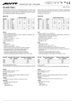
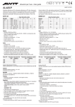
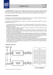
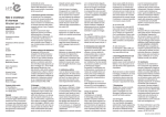
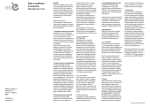
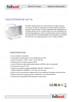
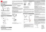
SELV
Istruzioni per l’uso - User guide
AL20D/P
MADE IN ITALY
Alimentatore elettronico per LED, multicorrente-multitensione con PFC attivo. Idoneo per alimentare sia strisce LED in tensione sia LED di potenza alimentati in corrente. La modalità di
funzionamento è selezionata attraverso il DIP SWITCH posto al disotto del coprimorsetto.
Regolazione della luminosità tramite funzione DALI, Push, interfaccia 1-10V o 0-10V.
Electronic ballast for LEDs, multi-multicurrent with active PFC. Suitable for voltage LED strips
and power current powered LEDs. The function mode is selected by means of the DIP SWITCH, which is below the terminal cover.
Light regulation via DALI, push function, interface 1-10V or 0-10V.
OUTPUT SET
DIMMING SET
220-240V
9,2W
11,5W
16,1W
18,4W
20W
20,4W
19,6W
19,8W
10,8W
21,6W
CC
CC
CC
CC
CC
CC
CC
CC
CV
CV
Output
200mA - 3-46V
250mA - 3-46V
350mA - 3-46V
400mA - 3-46V
500mA - 3-40V
600mA - 3-34V
700mA - 3-28V
900mA - 3-22V
12V - 900mA max
24V - 900mA max
Output Dip-Switch position
1
2
3
ON
ON
ON
ON
ON
ON
ON
ON
ON
ON
ON
ON
ON
ON
ON
ON
ON
ON
4
ON
-
5
ON
ON
Ingresso
> Nominale: 220/240 Vac 50/60 Hz.
> Idoneo per funzionamento a range esteso 90-264V - 50/60Hz con declassamento della
potenza. Contattare l’ufficio tecnico
> Morsettiera 1 x 2,5 mm2.
> Serracavo per cavi diametro Ø = 3...8 mm.
> Corrente massima: 130mA.
> Fattore di potenza λ: >0,9
> Armoniche corrente assorbita: secondo EN 61000-3-2.
Uscita
> Isolamento SELV.
> Morsettiera 1 x 0,5...1,5 mm2.
> Serracavo per cavi diametro Ø = 3...8 mm.
> Selezione corrente e tensione di uscita tramite DIP SWITCH (vedi tabella).
Ambiente
Temperatura ambiente massima Ta: -10÷50° C
Temperatura max sul punto Tc: 75°
Normative
EN61347-2-13, EN61347-1, EN62384, EN62384, EN55015, EN61000-3-2, EN61547,
IEC 62386-101/102/207
Protezioni
> Protezione al cortocircuito, sovraccarico, circuito aperto e termica
> Fltro antidisturbo EMI
Regolazioni
> Sono previste cinque distinte modalità di funzionamento lette all’avvio (le impostazioni
devono essere fatte tramite dip-switch prima dell’accensione):
1) ON/OFF (no dimming)
2) Push dimming (regolazione OFF, 2-100%) - tre profili: lento, veloce, su/giù
3) DALI (regolazione OFF, 2-100%)
- Power on: 100%
- System fail level: 100%
4) Dimming 1-10V
5) Dimming 0-10V
6) Slave
> Tempo dimmeraggio (min-max; max-min): profilo lento 8 secondi; profilo veloce 5 secondi; profilo su/giù 8 secondi.
> Livello Low in Push è diverso da 0 per distinguerlo da OFF.
> Riaccensione dopo mancanza rete:
- se in modalità dimmer 1-10V o 0-10V è letto il valore in ingresso in accordo alla programmazione;
- Se in modalità dimmer Push, parte dall’ultimo dato impostato.
- Se in modalità dimmer DALI, parte dall’ultimo dato impostato.
Dimming
ON/OFF
Push Slow
Push Fast
Push Up/Down
DALI
Potenziometro 1-10V passive
Potenziometro 1-10V active
Systems 0-10V active
Systems 0-10V passive
Slave
Output Dip-Switch position
1
2
3
ON
ON
ON
ON
ON
ON
ON
ON
ON
ON
ON
ON
ON
ON
ON
ON
4
-
5
ON
ON
-
Input
> Nominal: 220/240 Vac -10/+10% 50/60 Hz.
>Suitable for operation at extended range 90-264V - 50/60Hz with power derating of 50%.
For further information contact technical departement
> Terminal block for up to 1 x 2,5 mm2.
> Strain relief for cables with diameter Ø = 3...8 mm.
> Max Input Current: 0,25 A.
> Power factor λ: >0,9
> Harmonic content of mains current: according to EN 61000-3-2.
Output
> SELV insulation on output
> Terminal block for up to 1 x 0,5...1,5 mm2.
> Strain relief for cables with diameter Ø = 3...8 mm
> Selection of current and voltage output through DIP SWITCH (See table up)
Ambient
Ambient temperature Ta: -10÷50° C
Max case temperature on Tc: 75°
Normative
EN61347-2-13, EN61347-1, EN62384, EN62384, EN55015, EN61000-3-2, EN61547
IEC 62386-101/102/207
Protezioni
> Against input overvoltages from mains, short circuit and open circuit.
> Flter EMI suppression
Settings
> There are five distinct modes of operation read on startup (the settings have to be made by
dip-switch before ignition):
1) On/Off, no dimming
2) Push button dimming (control OFF, 2-100%) - three profiles: slow, fast, up/down;
3) DALI (control OFF, 2-100%)
- Power on: 100%
- System fail level: 100%
4) 0-10V Dimming
5) 1-10V Dimming
6) Slave
> Time dimming (min-max; max-min): slow profile 8 seconds, fast profile 5 seconds;
up/down profile 8 seconds.
> The low level in Push is different to 0 to distinguish it from OFF
> Restart after a power failure:
- If dimming 0-10V or 1-10V input value is read and ON according to the scheduling
- If dimmer Push mode, the last data set
- If DALI Push mode, the last data set
AL20D/P
Istruzioni per l’uso - User guide
Push
> Pressione breve del tasto per ON/OFF (rampe in accensione e spegnimento)
> Pressione lunga del tasto per dimmer
> Memorizzazione dell’ultimo dato di dimming. Ad ogni ON il driver parte dall’ultimo dato
impostato.
> Procedura di allineamento (necessaria per compensare gli errori di sincronizzazione quando si hanno tanti driver in parallelo): da posizione OFF/ON tenere premuto il tasto a lungo
(30sec) i driver si porteranno al 100%; alla successiva pressione del tasto il flusso luminoso inizierà a diminuire in accordo al profilo impostato.
> Massima lunghezza consigliata cavi PUSH: 15 m.
> Massima numero di alimentatori consigliati: 10
Profilo lento
> ad ogni pressione la dimmerazione continua fino al livello massimo (o minimo) e poi,
dopo circa 1s, si inverte. Tempo da minimo a massimo, 8s;
Profilo veloce
> ad ogni pressione la dimmerazione continua fino al livello massimo (o minimo) e poi,
dopo circa 1s, si inverte. Tempo da minimo a massimo, 5s;
Profilo Su/Giù
> ad ogni pressione la dimmerazione inverte il senso. Arrivato al livello minimo (o massimo) è mantenuto lo stato. Tempo da minimo a massimo, 8s.
1-10V
> È possibile utilizzare potenziometri fino a 100K. La luminosità dei LED varia proporzionalmente al segnale inviato al morsetto da 2 a 100%.
> La variazione della luminosità dei LED avviene in modo proporzionale o logaritmico a
seconda del modello di potenziometro utilizzato (consigliato logaritmico).
> Impostare il dip-switch 5 sulla posizione ON per potenziometri passivi: Iout max 1,4mA
> Impostare il dip-switch 5 sulla posizione OFF per potenziometri attivi. Impedenza di
ingresso 100K.
0-10V
> È possibile utilizzare sistemi 0-10V. La luminosità dei LED varia da 0 a 100% proporzionalmente al segnale inviato al morsetto.
> Impostare il dip-switch 5 sulla posizione OFF. Impedenza di ingresso 100K.
> Impostando il dip-switch 5 sulla posizione ON si ha comunque una Iout max 1,4mA
Slave
> È possibile utilizzare la funzione Slave solo in presenza di alimentatori con funzione Master
Note
> Nel caso di settaggio errato dei Dip, all’accensione il Driver parte e fa lampeggiare i Led
1s ON e 1s OFF.
Push
> Short press the Push key for ON/OFF (on and off ramps)
> Long press the Push key for dimmer
> Memory of the last data dimming. At each ON the driver starts from the last data set.
> Method of resynchronisation (sometimes the system could be out of sync, i.e. some lamps will be on, others off, etc.). In OFF/ON position press the Push key for a long time (30
sec), the driver will be 100% and the system will now be resynchronised.
> Total length of PUSH cables: 15 m.
> Maximum driver recommended: 10
Profile slow
> press the Push key, the dimming start up to the maximum (or minimum) and then,
after 1s, reverses. Time from minimum to maximum, 8s
Profile fast
> press the Push key, the dimming start up to the maximum (or minimum) and then,
after 1s, reverses. Time from minimum to maximum, 5s
Profile Up/Down
> press the Push key, the dimming reverses its direction. Arrived to the minimum (or maximum)the status is maintained. Time from minimum to maximum, 8s
1-10V
> You can use commercial dimmer 1-10V. The LED brightness varies proportionally to the
signal sent to the terminal from 2 to 100%.
> You can use 100K potentiometers. The variation in the brightness of the LEDs is in proportional or logarithmic depending on the model used potentiometer (recommended logarithmic).
> Set the dip-switch 5 to position ON for passive potentiometers, Iout max 1,4mA.
> Set the dip-switch 5 to position OFF for active potentiometers and domotic systems:
impedance 100K.
0-10V
> You can use systems 0-10V. The LED brightness varies from 0 to 100% proportionally to the
signal sent to the terminal.
> Set the dip-switch 5 to position OFF. Impedance 100K.
> By setting the dip-switch 5 ON you get an lout max 1,4mA.
Using dimmers active or passive
Slave
> You can use the Slave function only in presence of Driver with master function.
Notes
> In the case of wrong setting of Dip, the LED flashes 1s ON and 1s OFF.
Schema di collegamento On/Off, Push
Wiring diagram On/Off, Push
Schema di collegamento DALI, 1/10V, 0/10V
Wiring diagram DALI, 1/10V, 0/10V
R05-20-15
Dimensioni Dimension: 51x156x25h
Peso Weight: 0,05Kg
Garanzia: Alvit garantisce i propri prodotti per 24 mesi dalla data di fabbricazione indicata sui prodotti stessi. La garanzia copre tutti gli eventuali difetti di fabbricazione. La garanzia non copre gli eventuali danni causati da un utilizzo errato
e non conforme alle istruzioni di installazione e impiego. Qualsiasi modifica annulla la garanzia e può rendere pericoloso il prodotto. Alvit si riserva la possibilità, nel rispetto delle norme in vigore, di apportare, senza preavviso, modifiche
tecniche e dimensionali per migliorare le caratteristiche e le prestazioni dei prodotti.
Warranty: Alvit guarantees its products for 24 months from the manufacturing date shown on the products.The warranty covers any and all manufacturing defects. The warranty does not cover damage due to improper use not conforming to
the installation and operating instructions. Any modification will void the warranty and can make the product dangerous.Follow the instructions carefully to ensure correct and safe operation. The fixture cannot be modified. Alvit shall not be
responsible for any product damage caused by mounting procedures which do not comply with the instructions. Product installation shall be performed in a workmanlike fashion.