1
IT
Istruzioni per l’uso e l’installazione
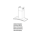
Cappa
GB
Instructions for use and installation
FR
Mode d’emploi et installation
DE
Bedienungsanleitung und Einrichtung
TR
Kullanım ve montaj talimatları
Cooker Hood
Hotte de Cuisine
Dunstabzugshaube
Davlumbaz
FOP 906
Libretto di Istruzioni
INDICE
CONSIGLI E SUGGERIMENTI ..............................................................................................................................................7
CARATTERISTICHE ..............................................................................................................................................................8
INSTALLAZIONE....................................................................................................................................................................9
USO ......................................................................................................................................................................................12
MANUTENZIONE .................................................................................................................................................................13
IT
2
2
Instructions Manual
INDEX
RECOMMENDATIONS AND SUGGESTIONS ....................................................................................................................14
CHARACTERISTICS............................................................................................................................................................15
INSTALLATION ....................................................................................................................................................................16
USE.......................................................................................................................................................................................19
MAINTENANCE....................................................................................................................................................................20
EN
3
3
Manuel d’Instructions
SOMMAIRE
CONSEILS ET SUGGESTIONS ..........................................................................................................................................21
CARACTERISTIQUES .........................................................................................................................................................22
INSTALLATION ....................................................................................................................................................................23
UTILISATION........................................................................................................................................................................26
ENTRETIEN..........................................................................................................................................................................27
FR
4
4
Bedienungsanleitung
INHALTSVERZEICHNIS
EMPFEHLUNGEN UND HINWEISE....................................................................................................................................28
CHARAKTERISTIKEN..........................................................................................................................................................29
MONTAGE............................................................................................................................................................................30
BEDIENUNG.........................................................................................................................................................................33
WARTUNG............................................................................................................................................................................34
DE
5
5
Kullanim Kilavuku
IÇERIKLER
TAVSIYELER VE ÖNERILER ..............................................................................................................................................35
ÖZELLIKLER ........................................................................................................................................................................36
MONTAJ ...............................................................................................................................................................................37
KULLANIM ............................................................................................................................................................................40
BAKIM...................................................................................................................................................................................41
TR
6
6
CONSIGLI E SUGGERIMENTI
Questo libretto di istruzioni per l'uso è previsto per più versioni dell'apparecchio.
Possibile che siano descritti singoli particolari della dotazione, che non riguardano il
Vostro apparecchio.
INSTALLAZIONE
• Il produttore declina qualsiasi responsabilità per danni dovuti ad installazione non
corretta o non conforme alle regole dell’arte.
• La distanza minima di sicurezza tra il Piano di cottura e la Cappa deve essere di
650 mm.
• Verificare che la tensione di rete corrisponda a quella riportata nella targhetta posta
all’interno della Cappa.
• Per Apparecchi in Classe Ia accertarsi che l’impianto elettrico domestico garantisca
un corretto scarico a terra.
• Collegare la Cappa all’uscita dell’aria aspirata con tubazione di diametro pari o
superiore a 120 mm. Il percorso della tubazione deve essere il più breve possibile.
• Non collegare la Cappa a condotti di scarico dei fumi prodotti da combustione (caldaie, caminetti, ecc.).
• Nel caso in cui nella stanza vengano utilizzati sia la Cappa che apparecchi non
azionati da energia elettrica (ad esempio apparecchi utilizzatori di gas), si deve
provvedere ad una aerazione sufficiente dell’ambiente. Se la cucina ne fosse
sprovvista, praticare un’apertura che comunichi con l’esterno, per garantire il richiamo d’aria pulita.
650 mm min.
USO
• La Cappa è stata progettata esclusivamente per uso domestico, per abbattere gli
odori della cucina.
• Non fare mai uso improprio della Cappa.
• Non lasciare fiamme libere a forte intensità sotto la Cappa in funzione.
• Regolare sempre le fiamme in modo da evitare una evidente fuoriuscita laterale
delle stesse rispetto al fondo delle pentole.
• Controllare le friggitrici durante l’uso: l’olio surriscaldato potrebbe infiammarsi.
• Non preparare alimenti flambè sotto la cappa da cucina; pericolo d'incendio.
• La Cappa non deve essere utilizzata da bambini o persone non abilitate all’uso
corretto.
MANUTENZIONE
• Prima di procedere a qualsiasi operazione di manutenzione, disinserire la Cappa
togliendo la spina elettrica o spegnendo l’interruttore generale.
• Effettuare una scrupolosa e tempestiva manutenzione dei Filtri secondo gli intervalli
consigliati.
• Per la pulizia delle superfici della Cappa è sufficiente utilizzare un panno umido e
detersivo liquido neutro.
sul prodotto o sulla confezione indica che il prodotto non deve essere
Il simbolo
considerato come un normale rifiuto domestico, ma deve essere portato nel punto di
raccolta appropriato per il riciclaggio di apparecchiature elettriche ed elettroniche.
Provvedendo a smaltire questo prodotto in modo appropriato, si contribuisce a evitare
potenziali conseguenze negative per l’ambiente e per la salute, che potrebbero derivare da uno smaltimento inadeguato del prodotto. Per informazioni più dettagliate sul
riciclaggio di questo prodotto, contattare l’ufficio comunale, il servizio locale di smaltimento rifiuti o il negozio in cui è stato acquistato il prodotto.
IT
7
7
CARATTERISTICHE
Ingombro
15
Componenti
Q.tà Componenti di Prodotto
1 Corpo Cappa completo di: Comandi, Luce, Gruppo
Ventilatore, Filtri
2
1 Camino Telescopico formato da:
2.1
1 Camino Superiore
2.2
1 Camino Inferiore
9
1 Flangia di Riduzione ø 150-120 mm
14.1
2 Prolunga Raccordo Uscita Aria
15
1 Raccordo Uscita Aria
Rif. Q.tà Componenti di Installazione
7.2.1 2 Staffe Fissaggio Camino Superiore
7.3
1 Staffa Sostegno Raccordo
11
6 Tasselli
12a
6 Viti 4,2 x 44,4
12c
6 Viti 2,9 x 9,5
Q.tà Documentazione
1 Libretto Istruzioni
14.1
Rif.
1
IT
7.3
12a 7.2.1
11
9
2.1
12c
2
2.2
11
12a
8
8
INSTALLAZIONE
1÷2
Foratura Parete e Fissaggio Staffe
116 116
650 min.
406,5
11
12a
X
7.2.1
Tracciare sulla Parete:
• una linea Verticale fino al soffitto o al limite superiore, al centro della zona prevista per il
montaggio della Cappa;
• una linea Orizzontale a: 650 mm min. sopra il Piano di Cottura.
• Appoggiare come indicato la Staffa 7.2.1 a 1-2 mm dal soffitto o dal limite superiore, allineando il suo centro (intagli) sulla linea Verticale di riferimento.
• Segnare i centri dei Fori della Staffa.
• Appoggiare come indicato la Staffa 7.2.1 a X mm sotto la prima staffa (X = altezza Camino
Superiore in dotazione), allineando il suo centro (intagli) sulla linea Verticale di riferimento.
• Segnare i centri dei Fori della Staffa.
• Segnare come indicato, un punto di riferimento a 116 mm dalla linea Verticale di riferimento, e 406,5 mm sopra la linea Orizzontale di riferimento.
• Ripetere questa operazione dalla parte opposta.
• Forare ø 8 mm i punti segnati.
• Inserire i tasselli 11 nei fori.
• Fissare la Staffa inferiore 7.2.1 utilizzando le Viti 12a (4,2 x 44,4 ) in dotazione.
• Fissare insieme la Staffa superiore 7.2.1 e la Staffa sostegno raccordo 7.3 utilizzando le 2
viti 12a (4,2 x 44,4) in dotazione.
• Avvitare 2 Viti 12a (4,2 x 44,4) in dotazione nei fori per il fissaggio del corpo Cappa, lasciando uno spazio di 5-6 mm fra la parete e la testa della vite.
IT
9
9
Montaggio Corpo Cappa
Vr
• Prima di agganciare il Corpo Cappa, serrare le 2 Viti Vr situate
sui punti di aggancio del Corpo Cappa.
• Agganciare il Corpo Cappa alle Viti 12a.
• Serrare definitivamente le Viti 12a di supporto.
• Agire sulle Viti Vr per livellare il Corpo Cappa.
12a
Connessioni
USCITA ARIA VERSIONE ASPIRANTE
Per installazione in Versione Aspirante collegare la Cappa alla
tubazione di uscita per mezzo di un tubo rigido o flessibile di
ø150 o 120 mm, la cui scelta è lasciata all'installatore.
• Per collegamento con tubo ø120 mm, inserire la Flangia di riduzione 9 sull’Uscita del Corpo Cappa.
• Fissare il tubo con adeguate fascette stringitubo. Il materiale
occorrente non è in dotazione.
• Togliere eventuali Filtri Antiodore al Carbone attivo.
ø 150
14.1
USCITA ARIA VERSIONE FILTRANTE
• Inserire il Raccordo 15 nella Staffa di Sostegno 7.3.
• Inserire lateralmente le Prolunghe Raccordo 14.1 sul Raccordo
15.
• Assicurarsi che l’uscita delle Prolunghe Raccordo 14.1 risulti
in corrispondenza delle bocchette del Camino sia in orizzontale
che in verticale.
• Collegare il Raccordo 15 all’Uscita del Corpo Cappa per mezzo di un tubo rigido o flessibile di ø150 mm, la cui scelta è
lasciata all'installatore.
• Assicurarsi della presenza del Filtro Antiodore al Carbone attivo.
IT
ø 120
9
15
ø 150
1
10
0
CONNESSIONE ELETTRICA
• Collegare la Cappa all’Alimentazione di Rete interponendo un
Interruttore bipolare con apertura dei contatti di almeno 3 mm.
• Rimuovere i Filtri antigrasso (vedi par. “Manutenzione”) e assicurarsi che il connettore del Cavo di alimentazione sia correttamente inserito nella presa dell’Aspiratore
Montaggio Camino
Camino superiore
• Allargare leggermente le due falde laterali, agganciarle dietro
le Staffe 7.2.1 e richiuderle fino a battuta.
• Fissare lateralmente alle Staffe con 4 Viti 12c (2,9 x 9,5) in
dotazione.
• Assicurarsi che l’uscita delle Prolunghe Raccordo risulti in corrispondenza delle bocchette del Camino.
Camino inferiore
• Allargare leggermente le due falde laterali del Camino, agganciarle tra il Camino superiore e la parete e richiuderle fino a
battuta.
• Fissare lateralmente la parte inferiore al Corpo Cappa, con 2
Viti 12c (2,9 x 9,5) in dotazione.
IT
7.2.1
12c
2.1
2
12c
2.2
12c
1
11
1
USO
T1
T2
T4
T3
T5
L
Quadro Comandi
T1
TASTO
ON/OFF Motore
T2
T3
T4
Velocità Velocità +
Velocità intensiva
T5
Delay
L
Luci
IT
FUNZIONI
Attiva e arresta il motore d’aspirazione. Sul display viene
visualizzato lo step di velocità precedentemente impostata.
Decrementa la velocità del motore: V3 →V2 → V1
Incrementa la velocità del motore: V1→V2→ V3
Attiva la velocità intensiva da qualsiasi velocità o da motore
spento.Per disinserirla basta premere di nuovo lo stesso tasto
o spegnere il motore. L’intensiva non è attivabile se è attiva
la funzione Delay. La velocità intensiva è temporizzata a 10
minuti: sul display viene visualizzato H e il punto in basso a
destra lampeggia una volta al secondo. Al termine dei 10 minuti il sistema torna automaticamente alla velocità precedentemente impostata.
Attiva e disattiva la modalità di arresto totale della cappa
(motore+luci) dopo 30 minuti: il display visualizza la velocità del motore e il punto in basso a destra lampeggia una
volta al secondo. Per disabilitare il Delay si può ripremere lo
stesso tasto oppure spegnere il motore
Accende e spegne le luci della cappa.
1
12
2
MANUTENZIONE
Filtri antigrasso
PULIZIA FILTRI ANTIGRASSO METALLICI AUTOPORTANTI
• Sono lavabili anche in lavastoviglie, e necessitano di essere
lavati ogni 2 mesi circa di utilizzo o più frequentemente, per un
uso particolarmente intenso.
• Togliere i Filtri uno alla volta,sostenendoli con una mano mentre con l’altra si tira la leva verso il basso.
• Lavare i Filtri evitando di piegarli, e lasciarli asciugare prima
di rimontarli.
• Rimontarli facendo attenzione a mantenere la maniglia verso la
parte visibile esterna
Filtro antiodore (Versione Filtrante)
SOSTITUZIONE FILTRO ANTIODORE AL CARBONE ATTIVO
• Non è lavabile e non è rigenerabile, va sostituito almeno ogni 4
mesi o più frequentemente, per un uso particolarmente intenso.
• Togliere i Filtri antigrasso metallici.
• Rimuovere il Filtro antiodore al Carbone attivo saturo, agendo
sugli appositi agganci.
• Montare il nuovo Filtro agganciandolo nella sua sede.
• Rimontare i Filtri antigrasso metallici.
Illuminazione
SOSTITUZIONE LAMPADE
Lampade alogene da 20 W
• Togliere il bloccavetro metallico a pressione facendo leva sotto
la ghiera, sostenendolo con una mano.
• Estrarre la lampadina alogena dal portalampada.
• Sostituirla con una nuova lampadina di uguali caratteristiche,
facendo attenzione ad inserire correttamente i due spinotti nella
sede del portalampade.
• Rimontare il bloccavetro a pressione.
IT
1
13
3
RECOMMENDATIONS AND SUGGESTIONS
The Instructions for Use apply to several versions of this appliance. Accordingly, you may find descriptions of individual features that do not apply to your
specific appliance.
INSTALLATION
• The manufacturer will not be held liable for any damages resulting from incorrect or improper installation.
• The minimum safety distance between the cooker top and the extractor hood
is 650 mm.
• Check that the mains voltage corresponds to that indicated on the rating plate
fixed to the inside of the hood.
• For Class I appliances, check that the domestic power supply guarantees adequate earthing.
Connect the extractor to the exhaust flue through a pipe of minimum diameter
120 mm. The route of the flue must be as short as possible.
• Do not connect the extractor hood to exhaust ducts carrying combustion fumes
(boilers, fireplaces, etc.).
• If the extractor is used in conjunction with non-electrical appliances (e.g. gas
burning appliances), a sufficient degree of aeration must be guaranteed in the
room in order to prevent the backflow of exhaust gas. The kitchen must have
an opening communicating directly with the open air in order to guarantee the
entry of clean air.
650 mm min.
USE
• The extractor hood has been designed exclusively for domestic use to eliminate kitchen smells.
• Never use the hood for purposes other than for which it has ben designed.
• Never leave high naked flames under the hood when it is in operation.
• Adjust the flame intensity to direct it onto the bottom of the pan only, making
sure that it does not engulf the sides.
• Deep fat fryers must be continuously monitored during use: overheated oil can
burst into flames.
• Do not flambè under the range hood; risk of fire
• The hood should not be used by children or persons not instructed in its correct use.
MAINTENANCE
• Switch off or unplug the appliance from the mains supply before carrying out
any maintenance work.
• Clean and/or replace the Filters after the specified time period.
• Clean the hood using a damp cloth and a neutral liquid detergent.
The symbol
on the product or on its packaging indicates that this product
may not be treated as household waste. Instead it shall be handed over to the
applicable collection point for the recycling of electrical and electronic equipment.
By ensuring this product is disposed of correctly, you will help prevent potential
negative consequences for the environment and human health, which could otherwise be caused by inappropriate waste handling of this product. For more detailed information about recycling of this product, please contact your local city
office, your household waste disposal service or the shop where you purchased
the product.
EN
1
14
4
CHARACTERISTICS
Dimensions
15
Components
Q.ty Product Components
1 Hood Body, complete with: Controls, Light, Blower,
Filters
2
1 Telescopic Chimney comprising:
2.1
1 Upper Section
2.2
1 Lower Section
9
1 Reducer Flange ø 150-120 mm
14.1
2 Air Outlet Connection Extension
15
1 Air Outlet Connection
Ref. Q.ty Installation Components
7.2.1 2 Upper Chimney Section Fixing Brackets
7.3
1 Air Outlet Connection Support
11
6 Wall Plugs
12a
6 Screws 4,2 x 44,4
12c
6 Screws 2,9 x 9,5
Q.ty Documentation
1 Instruction Manual
14.1
Ref.
1
EN
7.3
12a 7.2.1
11
9
2.1
12c
2
2.2
11
12a
1
15
5
INSTALLATION
1÷2
Wall drilling and bracket fixing
116 116
650 min.
406,5
11
12a
X
7.2.1
Wall marking:
• Draw a vertical line on the supporting wall up to the ceiling, or as high as practical, at the
centre of the area in which the hood will be installed.
• Draw a horizontal line at 650 mm above the hob.
• Place bracket 7.2.1 on the wall as shown about 1-2 mm from the ceiling or upper limit aligning the centre (notch) with the vertical reference line.
• Mark the wall at the centres of the holes in the bracket.
• Place bracket 7.2.1 on the wall as shown at X mm below the first bracket (X = height of the
upper chimney section supplied), aligning the centre (notch) with the vertical line.
• Mark the wall at the centres of the holes in the bracket.
• Mark a reference point as indicated at 116 mm from the vertical reference line and 406,5
mm above the horizontal reference line.
• Repeat this operation on the other side.
• Drill ø 8 mm holes at all the centre points marked.
• Insert the wall plugs 11 in the holes.
• Fix the lower bracket 7.2.1 using the 12a screws (4,2 x 44,4) supplied.
• Fix the upper bracket 7.2.1 and the air outlet connection support 7.3 together using the 2
screws 12a (4,2 x 44,4) supplied.
• Insert the two screws 12a (4,2 x 44,4) supplied in the hood body fixing holes, leaving a gap
of 5-6 mm between the wall and the head of the screw.
EN
1
16
6
Mounting the hood body
Vr
• Before attaching the hood body, tighten the two screws Vr located on the hood body mounting points.
• Hook the hood body onto the screws 12a.
• Fully tighten support screws 12a.
• Adjust screws Vr to level the hood body.
12a
Connections
DUCTED VERSION AIR EXHAUST SYSTEM
When installing the ducted version, connect the hood to the
chimney using either a flexible or rigid pipe ø 150 or 120 mm,
the choice of which is left to the installer.
• To install a ø 120 mm air exhaust connection, insert the reducer flange 9 on the hood body outlet.
• Fix the pipe in position using sufficient pipe clamps (not supplied).
• Remove any activated charcoal filters.
ø 150
14.1
RECIRCULATION VERSION AIR OUTLET
• Put connection 15 into the connection support 7.3.
• Insert the connection extension pieces laterally 14.1 in connection 15.
• Make sure that the outlet of the extension pieces 14.1 is horizontally and vertically aligned with the chimney outlets.
• Connect the air outlet connection 15 to the hood body outlet
using either a flexible or rigid pipe ø 150 mm, the choice of
which is left to the installer.
• Ensure that the activated charcoal filters have been inserted.
EN
ø 120
9
15
ø 150
1
17
7
ELECTRICAL CONNECTION
• Connect the hood to the mains through a two-pole switch having a contact gap of at least 3 mm.
• Remove the grease filters (see paragraph Maintenance) being
sure that the connector of the feeding cable is correctly inserted
in the socket placed on the side of the fan.
Flue assembly
Upper exhaust flue
• Slightly widen the two sides of the upper flue and hook them
behind the brackets 7.2.1, making sure that they are well
seated.
• Secure the sides to the brackets using the 4 screws 12c (2,9 x
9,5) supplied.
• Make sure that the outlet of the extensions pieces is aligned
with the chimney outlets.
7.2.1
12c
2.1
2
12c
2.2
12c
Lower exhaust flue
• Slightly widen the two sides of the flue and hook them between the upper flue and the wall, making sure that they are
well seated.
• Fix the lower part laterally to the hood body using the 2 screws
12c (2,9 x 9,5) supplied.
EN
1
18
8
USE
T1
T2
T4
T3
T5
L
Control panel
TOUCH CONTROL
T1 ON/OFF Motor
T2
T3
T4
Speed Speed +
Intensive speed
T5
Delay
L
Lighting
EN
FUNCTION
Switches the hood motor on and off. The latest selected
speed appears on the display.
Decreases the suction speed: V3 → V2 → V1
Increases the suction speed: V1 → V2 → V3
Activates the intensive speed from any previously selected
speed. The intensive speed can be activated even when the
motor is OFF. By pressing the same touch control once again
or by switching off the motor this function can be deactivated. Intensive speed cannot be activated when the delay
function is on. Intensive speed has been timed at 10 minutes:
H appears on the display and a spot down on the right side
flashes once a second. After 10 minutes the system activates
automatically the latest selected speed.
Activates and deactivates the delayed shutdown of the hood
(motor + lighting) at 30 minutes: the selected speed of the
hood appears on the display and a spot down on the right
side flashes once a second. By pressing the same touch control once again or by switching off the motor delay function
can be deactivated.
Turns light on and off.
1
19
9
MAINTENANCE
Grease filters
CLEANING METAL SELF- SUPPORTING GREASE FILTERS
• The filters must be cleaned every 2 months of operation, or
more frequently for particularly heavy usage, and can be
washed in a dishwasher.
• Remove the filters one at a time holding them up with one
hand and pulling the handle downwards with the other hand at
the same time.
• Wash the filters, taking care not to bend them. Allow them to
dry before refitting.
• When refitting the filters, make sure that the handle is visible
on the outside.
Activated charcoal filter (Recirculation version)
REPLACING THE ACTIVATED CHARCOAL FILTER
• The filter is not washable and cannot be regenerated, and
must be replaced approximately every 4 months of operation, or more frequently for particularly heavy usage.
• Remove the metal grease filters
• Remove the saturated activated carbon filter by releasing the
fixing hooks
• Fit the new filter by hooking it into its seating
• Replace the metal grease filters.
Lighting
LIGHT REPLACEMENT
20 W halogen light.
• Remove the snap-on lamp cover by levering it from under the
metal ring, supporting it with one hand.
• Remove the halogen lamp from the lamp holder by pulling
gently.
• Replace the lamp with a new one of the same type, making
sure that you insert the two pins properly into the housings on
the lamp holder.
• Replace the snap-on lamp cover.
EN
2
20
0
CONSEILS ET SUGGESTIONS
La présente notice d'emploi vaut pour plusieurs versions de l'appareil. Elle peut contenir
des descriptions d'accessoires ne figurant pas dans votre appareil.
INSTALLATION
• Le fabricant décline toute responsabilité en cas de dommage dû à une installation non
correcte ou non conforme aux règles de l’art.
• La distance minimale de sécurité entre le plan de cuisson et la hotte doit être de 650 mm
au moins.
• Vérifier que la tension du secteur correspond à la valeur qui figure sur la plaquette apposée à l’intérieur de la hotte.
• Pour les Appareils appartenant à la Ière Classe, veiller à ce que la mise à la terre de
l’installation électrique domestique ait été effectuée conformément aux normes en vigueur.
• Connecter la hotte à la sortie d’air aspiré à l’aide d’une tuyauterie d’un diamètre égal ou
supérieur à 120 mm. Le parcours de la tuyauterie doit être le plus court possible.
• Eviter de connecter la hotte à des conduites d’évacuation de fumées issues d’une combustion tel que (Chaudière, cheminée, etc…).
• Si vous utilisez des appareils qui ne fonctionnent pas à l’électricité dans la pièce ou est
installée la hotte (par exemple: des appareils fonctionnant au gaz), vous devez prévoir
une aération suffisante du milieu. Si la cuisine en est dépourvue, pratiquez une ouverture
qui communique avec l’extérieur pour garantir l’infiltration de l’air pur.
650 mm min.
UTILISATION
• La hotte a été conçue exclusivement pour l’usage domestique, dans le but d’éliminer les
odeurs de la cuisine.
• Ne jamais utiliser abusivement la hotte.
• Ne pas laisser les flammes libres à forte intensité quand la hotte est en service.
• Toujours régler les flammes de manière à éviter toute sortie latérale de ces dernières par
rapport au fond des marmites.
• Contrôler les friteuses lors de l’utilisation car l’huile surchauffée pourrait s’enflammer.
• Ne pas préparer d’aliments flambés sous la hotte de cuisine : risque d’incendie
• La hotte ne doit pas être utilisée par des enfants ou des personnes ne pouvant pas assurer une utilisation correcte.
ENTRETIEN
• Avant de procéder à toute opération d’entretien, retirer la hotte en retirant la fiche ou en
actionnant l’interrupteur général.
• Effectuer un entretien scrupuleux et en temps dû des Filtres, à la cadence conseillée.
• Pour le nettoyage des surfaces de la hotte, il suffit d’utiliser un chiffon humide et détersif
liquide neutre.
Le symbole
sur le produit ou son emballage indique que ce produit ne peut être traité
comme déchet ménager. Il doit plutôt être remis au point de ramassage concerné, se chargeant
du recyclage du matériel électrique et électronique. En vous assurant que ce produit est éliminé
correctement, vous favorisez la prévention des conséquences négatives pour l’environnement et
la santé humaine qui, sinon, seraient le résultat d’un traitement inapproprié des déchets de ce
produit. Pour obtenir plus de détails sur le recyclage de ce produit, veuillez prendre contact avec
le bureau municipal de votre région, votre service d’élimination des déchets ménagers ou le
magasin où vous avez acheté le produit.
FR
2
21
1
CARACTERISTIQUES
Encombrement
15
Composants
Q.té Composants de Produit
1 Corps Hotte équipé de:Commandes, Lumière, Groupe
Ventilateur,Filtres
2
1 Cheminée Télescopique formée de :
2.1
1 Cheminée Supérieure
2.2
1 Cheminée Inférieure
9
1 Flasque de Réduction ø 150-120 mm
14.1
2 Rallonge Raccord Sortie Air
15
1 Raccord Sortie Air
Réf. Q.té Composants pour l ’installation
7.2.1 2 Brides Fixation Cheminée Supérieure
7.3
1 Bride Support Raccord
11
6 Chevilles
12a
6 Vis 4,2 x 44,4
12c
6 Vis 2,9 x 9,5
Q.té Documentation
1 Manuel d’instructions
14.1
Réf.
1
FR
7.3
12a 7.2.1
11
9
2.1
12c
2
2.2
11
12a
2
22
2
INSTALLATION
1÷2
Perçage Paroi et Fixation Brides
116 116
650 min.
406,5
11
12a
X
7.2.1
Tracer sur la paroi:
• une ligne verticale allant jusqu’au plafond ou à la limite supérieure, au centre de la zone
prévue pour le montage de la hotte;
• une ligne horizontale à 650 mm min. au-dessus du plan de cuisson.
• Poser comme indiqué une bride 7.2.1 sur la paroi à 1-2 mm du plafond ou de la limite supérieure, en alignant son centre (découpes) sur la ligne verticale de repère.
• Marquer les centres des trous rainurés de la bride.
• Poser comme indiqué la bride 7.2.1 à X mm sous la première bride (X = hauteur cheminée
supérieure fournie), en alignant son centre (découpes) sur la ligne verticale de repère.
• Marquer les centres des trous rainurés de la bride.
• Marquer comme indiqué, un point de référence à 116 mm de la ligne verticale de repère, et
406,5 mm au-dessus de la ligne horizontale de repère.
• Répéter cette opération sur le côté opposé.
• Percer de ø 8 mm tous les points marqués.
• Insérer les chevilles 11 dans les trous.
• Fixer la bride inférieure 7.2.1 en utilisant les vis 12a (4,2 x 44,4) fournies.
• Fixer ensemble la bride supérieure 7.2.1 et le support 7.3 en utilisant les vis 12a (4,2 x 44,4)
fournies.
• Visser les 2 vis 12a (4,2 x 44,4) fournies dans les trous de fixation du corps hotte, en laissant
un espace de 5-6 mm entre le mur et la tête de la vis.
FR
2
23
3
Montage Corps Hotte
Vr
• Avant d’accrocher le corps hotte, serrer les deux vis Vr situées
sur les points d’accrochage du corps hotte.
• Accrocher le corps hotte aux vis 12a prévues à cet effet.
• Serrer définitivement les vis 12a de support.
• Agir sur les vis Vr pour niveler le corps hotte.
12a
Branchements
SORTIE AIR VERSION ASPIRANTE
En cas d’installation en version aspirante, brancher la hotte à la
tuyauterie de sortie via un tube rigide ou flexible de ø 150 ou 120
mm, au choix de l’installateur.
• En cas de branchement avec un tube de ø120 mm, insérer le
flasque de réduction 9 sur la sortie du corps de la hotte.
• Fixer le tube par des colliers appropriés. Le matériau nécessaire n’est pas fourni.
• Retirer les éventuels filtres anti-odeur au charbon actif.
ø 150
14.1
SORTIE AIR VERSION FILTRANTE
• Insérer le raccord 15 dans le support 7.3.
• Insérer latéralement les rallonges raccord 14.1 sur le raccord
15.
• S’assurer que la sortie des rallonges raccord 14.1 se trouve au
niveau des bouches de la cheminée aussi bien en horizontal
qu’en vertical.
• Brancher le raccord 15 à la sortie du corps de la hotte avec un
tube rigide ou flexible de ø 150 mm, selon le choix de
l’installateur.
• S’assurer de la présence des filtres anti-odeur au charbon actif.
FR
ø 120
9
15
ø 150
2
24
4
BRANCHEMENT ELECTRIQUE
• Brancher la hotte sur le secteur en interposant un interrupteur
bipolaire avec ouverture des contacts d’au moins 3 mm.
• Enlever les filtres à graisse (voir § "Entretien") et s'assurer que
le connecteur du câble d'alimentation soit bien branché dans la
prise du diffuseur.
Montage Cheminée
Cheminée supérieure
• Elargir légèrement les deux bords latériaux, et les accrocher
derrières les brides 7.2.1 ; refermer
jusqu’à la butée.
• Fixer latéralement aux brides à l’aide des 4 vis
12c fournies.
• S’assurer que la sortie des rallonges raccord se trouve au niveau des bouches de la cheminée.
7.2.1
12c
2.1
2
12c
2.2
12c
Cheminée inférieure
• Elargir légèrement les deux bords latériaux de la Cheminée et
les accrocher entre la Cheminée supérieure et la paroi; refermer
jusqu’à la butée.
• Fixer latéralement la partie inférieure au corps
hotte, à l’aide des deux 2 vis 12c fournies.
FR
2
25
5
UTILISATION
T1
T2
T3
T4
T5
L
Tableau des commandes
T1
TOUCHE
ON/OFF Moteur
T2
T3
T4
Vitesse Vitesse +
Vitesse intensive
T5
Delay
L
Éclairage
FR
FONCTIONS
Actionne et arrête le moteur d’aspiration. Sur l’afficheur est
visualisé le pas de la vitesse précédemment sélectionnée.
Réduit la vitesse du moteur: V3 → V2 → V1
Augmente la vitesse du moteur: V1 → V2 → V3
Actionne la vitesse intensive en partant d’une vitesse quelconque ou lorsque le moteur est éteint. Pour la désactiver, il
suffit d’appuyer à nouveau sur la même touche qui a été utilisée ou d’éteindre le moteur. La vitesse intensive ne peut pas
être actionnée si la fonction Delay est active. La vitesse intensive est temporisée sur 10 minutes: sur l’afficheur est visualisée l’inscription H et le point en bas à droite clignote
une fois par seconde. Lorsque 10 minutes se sont écoulées, le
système retourne automatiquement à la vitesse précédemment sélectionnée.
Actionne et désactive la modalité d’arrêt total de la hotte
(moteur+éclairage) après 30 minutes: l’afficheur visualise la
vitesse du moteur et le point en bas à droite clignote une fois
par seconde. Pour invalider la fonction Delay on peut appuyer à nouveau sur la même touche ou éteindre le moteur.
Allume et éteint l’éclairage de la hotte.
2
26
6
ENTRETIEN
Filtres anti-graisse
NETTOYAGE FILTRES ANTI-GRAISSE METALLIQUES AUTOPORTEURS
• Lavables au lave-vaisselle, ils doivent être lavés environ tous
les 2 mois d’emploi ou plus fréquemment en cas d’emploi particulièrement intense.
• Enlevez les filtres l’un après l’autre en les soutenant avec une
main et en tirant en même temps la poignée vers le bas avec
l’autre main.
• Laver les filtres en évitant de les plier et les laisser sécher avant
de les remonter.
• Remonter les filtres en veillant à ce que la poignée reste vers la
partie visible externe
Filtre anti-odeur (Version filtrante)
REMPLACEMENT FILTRE AU CHARBON ACTIF
• Ni lavable, ni régénérable, le remplacer au moins tous les 4
mois d’emploi ou plus fréquemment en cas d’emploi particulièrement intense.
• Retirer les filtres anti-graisse métalliques.
• Retirer le filtre anti-odeur au charbon actif colmaté, en agissant sur les crochets prévus à cet effet.
• Monter le nouveau filtre anti-odeur au charbon
actif.
• Remonter les filtres anti-graisse métalliques.
Eclairage
REMPLACEMENT LAMPES
Lampe halogène de 20 W.
• Enlever le dispositif métallique de blocage du verre par encliquetage en exerçant une pression sous l’embout en le soutenant
d’une main.
• Extraire la lampe du support
• Remplacer la lampe par une nouvelle ayant le mêmes caractéristiques, en prenant soin d'insérer correctement les deux fiches
dans le support.
• Remonter le dispositif de blocage du verre par encliquetage.
FR
2
27
7
EMPFEHLUNGEN UND HINWEISE
Diese Gebrauchsanleitung gilt für mehrere Geräte-Ausführungen. Es ist möglich, dass
einzelne Ausstattungsmerkmale beschrieben sind, die nicht auf Ihr Gerät zutreffen.
MONTAGE
• Das Gerät darf nur vom Fachpersonal angeschlossen werden.
• Der Hersteller haftet nicht für Schäden, die auf eine fehlerhafte und unsachgemäße Montage zurückzuführen sind.
• Der minimale Sicherheitsabstand zwischen Kochmulde und Haube muss 650 mm betragen.
• Prüfen, ob die Netzspannung mit dem Wert auf dem im Haubeninneren angebrachten Schild übereinstimmt.
• Bei Geräten der Klasse I ist sicherzustellen, dass die elektrische Anlage des Wohnhauses
über eine vorschriftsmäßige Erdung verfügt.
• Das Anschlussrohr der Haube zur Luftaustrittsöffnung sollte möglicherweise einen
Durchmesser von 150 mm aufweisen. Der Rohrverlauf muss so kurz wie möglich sein.
• Die Haube darf an keine Entlüftungsschächte angeschlossen werden, in die Verbrennungsgase (Heizkessel, Kamine usw.) geleitet werden.
• Werden im Raum außer der Dunstabzugshaube andere, nicht elektrisch betriebene (z.B.
gasbetriebene) Geräte verwendet, muss für eine ausreichende Belüftung gesorgt werden.
Sollte die Küche diesbezüglich nicht entsprechen, ist an einer Aussenwand eine Öffnung
anzubringen, die Frischluftzufuhr gewährleistet.
650 mm min.
BEDIENUNG
• Die Dunstabzugshaube ist ausschließlich zum Einsatz im privaten Haushalt und zur Beseitigung von Küchengerüchen vorgesehen.
• Bei unsachgemäßer Benutzung wird keine Haftung übernommen.
Achtung! Große Flammen bei eingeschalteter Haube niemals unbedeckt lassen.
• Die Intensivität der Flamme ist so zu regulieren, dass sie den Topfboden nicht überragt.
Achtung! Frittiergeräte müssen während des Gebrauchs stets beaufsichtigt werden: Überhitztes Öl kann sich entzünden.
• Keine flambierten Speisen unter der Abzugshaube zubereiten: Brandgefahr.
• Die Dunstabzugshaube darf von Kindern oder Personen, die hinsichtlich der Bedienung
nicht unterwiesen wurden, keinesfalls verwendet werden.
WARTUNG
• Bevor Wartungsarbeiten durchgeführt werden, muss die Stromzufuhr zur Haube unterbrochen werden, indem der Stecker gezogen oder der Hauptschalter abgeschaltet wird.
• Bei der Filterwartung müssen die vom Hersteller empfohlenen Zeiträume zum Austauschen der Filter genauestens eingehalten werden.
• Zur Reinigung der Haubenflächen Wir empfehlen ein feuchtes Tuch und ein mildes Flüssigreinigungsmittel.
• Bitte keine Reinigungsmittel mit Scheuermittel verwenden. Die Oberfläche wird damit
verkratzt.
Das Symbol
auf dem Produkt oder seiner Verpackung weist darauf hin, dass dieses
Produkt nicht als normaler Haushaltsabfall zu behandeln ist, sondern an einem Sammelpunkt
für das Recycling von elektrischen und elektronischen Geräten abgegeben werden muss.
Durch Ihren Beitrag zum korrekten Entsorgen dieses Produkts schützen Sie die Umwelt und
die Gesundheit Ihrer Mitmenschen. Umwelt und Gesundheit werden durch falsches Entsorgen gefährdet. Weitere Informationen über das Recycling dieses Produkts erhalten Sie von
Ihrem Rathaus, Ihrer Müllabfuhr oder dem Geschäft, in dem Sie das Produkt gekauft haben.
DE
2
28
8
CHARAKTERISTIKEN
Platzbedarf
15
Komponenten
Pos.
1
St.
1
2
2.1
2.2
9
14.1
15
1
1
1
1
2
1
Produktkomponenten
Haubenkörper mit Schaltern, Beleuchtung, Gebläsegruppe, Filter
Teleskopkamin bestehend aus:
oberer Kaminteil
unterer Kaminteil
Reduzierflansch ø 150-120 mm
Verlängerung Luftaustritt-Anschlussstück
Luftaustritt-Anschlussstück
Pos.
7.2.1
7.3
11
12a
12c
St.
2
1
6
6
6
Montagekomponenten
Befestigungsbügel oberer Kaminteil
Bügel für Anschlusshalter
Dübel
Schrauben 4,2 x 44,4
Schrauben 2,9 x 9,5
St.
1
Dokumentation
Bedienungsanleitung
DE
14.1
7.3
12a 7.2.1
11
9
2.1
12c
2
2.2
11
12a
2
29
9
MONTAGE
1÷2
Bohren der Befestigungslöcher und Fixieren der Befestigungsbügel
116 116
650 min.
406,5
11
12a
X
7.2.1
Achtung: Bitte beachten Sie bei der Montage das Gewicht der kompletten Haube. Die Tragfähigkeit der Decke oder alternativ der Trägerplatte für diese Zugbelastung muss vor der Montage geprüft und gegebenenfalls durch die Anbringung von geeigneten Befestigungs- oder
Stabilisierungselementen hergestellt werden. Kann eine hinreichende Tragfähigkeit nicht sichergestellt werden, ist von einer Montage abzusehen
Nachstehende Linien an die Wand zeichnen:
• eine vertikale Linie bis zur Decke oder oberen Begrenzung, und zwar in der Mitte des Bereiches, in dem die Haube montiert werden soll;
• eine horizontale Linie: mit einem minimalen Abstand von 650 mm zur Kochfläche.
• Einen Bügel 7.2.1 zirka 1-2 mm unter der Decke oder oberen Begrenzung an die Wand legen und seinen Mittelpunkt (Einschnitte) auf die vertikale Bezugslinie ausrichten.
• Die Mitte der beiden Bügellöcher an der Wand markieren.
• Den zweiten Bügel 7.2.1 an die Wand legen, wobei ein Abstand X mm vom oberen Bügel
einzuhalten ist (X = Höhe des jeweiligen oberen Kaminteils); den Mittelpunkt (Einschnitte)
auf die vertikale Bezugslinie ausrichten.
• Die Mitte der Bügellöcher an der Wand markieren.
• Wie beschrieben einen Bezugspunkt 116 mm von der vertikalen Bezugslinie und 406,5 mm
oberhalb der horizontalen Bezugslinie kennzeichnen.
• Gleichermaßen an der gegenüberliegenden Seite vorgehen.
• Mit einem Bohrer ø 8 mm die markierten Punkte bohren.
• Die Dübel 11 in die Bohrungen einfügen.
• Den unteren Bügel mit den mitgelieferten Schrauben 12a (4,2 x 44,4) fixieren.
• Den Bügel für Anschlusshalter mit den 2 mitgelieferten Schrauben 12a (4,2 x 44,4) auf den
oberen Bügel 7.2.1 befestigen.
• 2 der mitgelieferten Schrauben 12a (4,2 x 44,4) bei den Befestigungslöchern des Haubenkörpers einschrauben, wobei zwischen Wand und Schraubenkopf ein Freiraum von 5-6 mm
zu belassen ist.
DE
3
30
0
Montage des Haubenkörpers
Vr
• Bevor der Haubenkörper eingehakt wird, die 2 Schrauben Vr
bei den Haubenkörper-Anhakpunkten festziehen.
• Den Haubenkörper bei den Schrauben 12a einhängen.
• Die Halteschrauben 12a definitiv festziehen.
• Den Haubenkörper mit Hilfe der Schrauben Vr ausrichten.
12a
Anschluss der Abluftversion
Bei Abluftbetrieb kann die Haube vom Installateur wahlweise
mittels Rohr oder Schlauch (ø 150 oder 120 mm) an die Außenrohrleitung angeschlossen werden.
• Bei Verwendung eines Anschlussrohres ø 120 den Reduzierflansch 9 am Haubenaustritt anbringen.
• Das Rohr mit geeigneten Rohrschellen fixieren. Das hierzu
erforderliche Material wird nicht mitgeliefert.
• Eventuell vorhandene Aktivkohlefilter entnehmen.
ø 150
ø 120
9
Achtung! Alle Querschnittänderungen oder Richtungsänderungen des Abluftkanals reduzieren die Leistung der Haube.
14.1
Anschluss der Umluftversion
• Den Anschluss 15 am Anschlusshalter 7.3 anbringen.
• Die Verlängerungen 14.1 beim Anschluss 15 seitlich einfügen.
• Überprüfen, ob die Verlängerungen 14.1 mit den entsprechenden Kaminstutzen sowohl horizontal wie auch vertikal übereinstimmen.
• Vom Installateur wahlweise mittels Rohr oder Schlauch (ø 150
mm), den Anschluss 15 am Haubenaustritt anbringen.
• Kontrollieren, ob der Aktivkohle-Geruchsfilter montiert ist.
DE
15
ø 150
3
31
1
Elektroanschluss
•
•
Vor der Installation die Netzspannung durch herausdrehen der
Sicherung oder ausschalten des Hauptschalters stromlos machen.
Bei Anschluss der Haube an das Stromnetz muss ein zweipoliger Schalter mit einem Öffnungsweg von mindestens 3
mm zwischengeschaltet werden.
Entfernen Sie die Fettfilter (s. Abschnitt „Wartung“) und
versichern Sie sich, daß die Kabelverbindung in die Steckdose des Gebläses einwandfrei eingesteckt wird.
Achtung: Das Gerät nur an die Netzspannung die im Typenschild angegeben ist anschließen.
Kaminmontage
Oberer Kaminteil
• Die beiden seitlichen Schenkel leicht auseinanderbiegen, hinter
den Bügeln 7.2.1 einhängen und bis zum Anschlag wieder
schließen.
• Bei den Bügeln 7.2.1 mit Hilfe der 4 mitgelieferten Schrauben
12c fixieren.
• Überprüfen, ob die Verlängerungen mit den entsprechenden
Kaminstutzen übereinstimmen.
7.2.1
12c
2.1
2
12c
2.2
12c
Unterer Kaminteil
• Die beiden seitlichen Schenkel des Kaminteils leicht auseinander biegen, zwischen dem oberen Kaminteil und der Wand
einhängen und bis zum Anschlag wieder schließen.
• Den unteren Teil seitlich am Haubenkörper mit 2 der mitgelieferten Schrauben 12c fixieren.
DE
3
32
2
BEDIENUNG
T1
T2
T4
T3
T5
L
Bedienfeld
TASTE
T1 Motor ON/OFF
FUNKTIONEN
Schaltet den Gebläsemotor ein und aus. Auf dem Display wird die
zuvor eingestellte Geschwindigkeitsstufe angezeigt.
T2 Geschwindigkeit -
Erhöht die Geschwindigkeit des Motors: V3 → V2 → V1
T3 Geschwindigkeit +
Verringert die Geschwindigkeit des Motors: V1 → V2 → V3
T4 Intensivstufe
Aktiviert die Intensivstufe von jeder Geschwindigkeitsstufe aus
oder bei ausgeschaltetem Motor. Zum Ausschalten einfach die selbe Taste erneut drücken oder den Motor ausschalten. Bei aktivierter Delay-Funktion lässt sich die Intensivstufe nicht aktivieren. Die
Intensivstufe dauert 10 Minuten: Auf dem Display wird H angezeigt und der Punkt unten rechts blinkt einmal pro Sekunde. Nach
10 Minuten kehrt das System automatisch in die zuvor eingestellte
Geschwindigkeitsstufe zurück.
T5 Delay
Aktiviert und deaktiviert den Modus Komplettes Ausschalten der
Haube (Motor + Beleuchtung) nach 30 Minuten: Auf dem Display
wird die Geschwindigkeitsstufe des Motors angezeigt und der
Punkt unten rechts blinkt einmal pro Sekunde. Zum Deaktivieren
der Delay-Funktion die selbe Taste erneut drücken oder den Motor
ausschalten.
L
Schaltet die Beleuchtung der Haube ein und aus.
DE
Beleuchtung
3
33
3
WARTUNG
Fettfilter
SELBSTTRAGENDER METALLFETTFILTER REINIGUNG
• Sie müssen nach 2-monatigem Betrieb bzw. bei starkem Einsatz auch häufiger gereinigt werden, was im Geschirrspüler
möglich ist.
• Einen Filter nach dem anderen entfernen. Halten Sie den Filter
mit einer Hand fest und ziehen Sie den Griff mit der anderen
Hand gleichzeitig nach unten.
• Die Filter reinigen (darauf achten, sie nicht zu verbiegen) und
vor der Remontage trocknen lassen.
• Bei der Remontage ist darauf zu achten, dass sich der Griff auf
der sichtbaren Außenseite befindet.
Geruchsfilter (Umluftversion)
AUSTAUSCHEN DER AKTIVKOHLE FILTER
• Dieser Filter kann weder gewaschen noch wiederverwendet
werden und ist alle 4 Betriebsmonate bzw. bei starkem Einsatz
auch häufiger auszutauschen.
• Die Metallfettfilter entfernen.
• Den gesättigten Aktivkohle-Geruchsfilter aushaken.
• Den neuen Filter in seinem Sitz einhaken.
• Die Metallfettfilter wieder montieren.
• Die Kohlefilter können mit dem Hausmüll entsorgt werden.
Beleuchtung
AUSWECHSELN DER LAMPEN
Halogenlampe 20 W
• Vor dem Auswechseln der Lampen, die mittels Eindrücken
befestigte Glashalterung aus Metall durch Anheben der Zwinge
entfernen und die Halterung dabei mit einer Hand stützen.
• Die Lampe aus der Halterung nehmen.
• Die Lampe durch eine gleichwertige ersetzen und bei der Remontage darauf achten, daß die beiden Steckerstifte vorschriftsmäßig in die Lampenfassung eingeführt werden.
• Die Glashalterung wieder eindrücken.
DE
3
34
4
TAVSIYELER VE ÖNERILER
Bu kullanma talimatȚ birden fazla cihaz modeli için geçerlidir.
CihazȚnȚza uymayan bazȚ donanȚm özellikleri tarif edilmiú olabilir.
MONTAJ
• YalnȚú veya eksik montajdan do÷an herhangi bir zararȚn sorumlulu÷u üreticiye
ait de÷ildir.
• Davlumbaz ile piúirici cihazȚn ocak kȚsmȚ arasȚndaki minimum güvenlik mesafesi 650 mm.dir.
• Besleme voltajȚnȚn, davlumbaz içerisine yerleútirilen bilgi etiketinde belirtilenle
aynȚ olup olmadȚ÷ȚnȚ kontrol edin.
• SȚnȚf I elektrikli aletleri için, güç kayna÷ȚnȚn yeterli topraklamayȚ sa÷layȚp
sa÷lamadȚ÷ȚnȚ kontrol edin. Minimum 120 mm çapȚnda bir boru yoluyla davlumbazȚ çȚkȚú bacasȚna ba÷layȚn. Baca ba÷lantȚsȚ mümkün oldu- ÷unca kȚsa
olmalȚdȚr.
• Davlumbaz borusunu yanȚcȚ duman taúȚyan baca deli÷ine (buhar kazanȚ, úömine, vb.) ba÷lamayȚn.
• DavlumbazȚn elektrikle çalȚúmayan aletlerle (örne÷in; gazlȚ cihazlar) ba÷ȚntȚlȚ
olarak kullanȚlmamasȚ halinde çȚkȚú gazȚnȚn geri tepmesini önlemek amacȚyla
odada yeterli bir havalandȚrma sa÷lanmalȚdȚr. Temiz hava giriúini temin etmek
için mutfakta do÷rudan dȚúarȚya açȚlan bir açȚklȚk bulunmalȚdȚr.
650 mm min.
KULLANIM
• Davlumbaz mutfaktaki kokularȚn emilmesi amacȚyla evlerde kullanȚm için
tasarlanmȚútȚr.Ticari ve endüstriyel amaçlar için kullanmayȚnȚz.
• DavlumbazȚ tasarlandȚ÷Ț amaçlarȚn dȚúȚnda kesinlikle kullanmayȚnȚz.
• Davlumbaz çalȚúȚrken altȚnda kesinlikle yüksek çȚplak ateú bȚrakmayȚn.
• Alev yo÷unlu÷unu do÷rudan tencerenin altȚnda kalacak úekilde ayarlayȚn,
kenarlarȚnȚ sarmadȚ÷Țndan emin olun.
• Ya÷da kȚzartma tavalarȚnȚ kullanȚrken sürekli olarak takip edin: fazla ȚsȚnan ya÷
tutuúabilir.
• Kapa÷ın altında kıvılcımdan kaçının, yangın riski
• Davlumbaz çocuklar veya do÷ru kullanȚm konusunda bilgisi olmayan kiúiler
tarafȚndan kullanȚlmamalȚdȚr.
BAKIM
• Herhangi bir bakȚm iúlemini gerçekleútirmeden önce davlumbazȚ kapatȚn veya
fiúini çȚkarȚn.
• Filtreleri belirtilen zamanlarda temizleyin ve / veya de÷iútirin.
• CihazȚ nemli bir bez ve nötr bir sȚvȚ deterjan kullanarak temizleyin.
Ürün veya paketi üzerindeki
sembolü, bu ürünün normal bir evsel atık olarak
görülmemesi ve bu tip elektrikli veya elektronik cihazların atıldı÷ı dönüúümlü toplama noktalarına terkedilmesi gerekti÷ine iúaret eder. Bu ürünü gerekti÷i gibi elimine etme kurallarına uyarsanız çevre ve insan sa÷lı÷ı üzerindeki olumsuz etkilerini bertaraf etmeye katkı sa÷lamıú olursunuz. Bu ürünün geri dönüúüm koúulları
hakkında daha ayrıntılı bilgi için hudutları içinde bulundu÷unuz belediyenin ilgili
diaresine, atık yoketme servisine veya ürünün satıcısına danıúınız.
TR
3
35
5
ÖZELLIKLER
Boyutlar
15
Parçalar
Adet Ürünün parçaları
1 ùunlardan oluúan davlumbaz gövdesi: Kumandalar,
Lamba, Fan grubu, Filtreler
2
1 ùunlardan oluúan teleskopik baca:
2.1
1 Üst baca
2.2
1 Alt baca
9
1 Redüksiyon Flanúı ø 150-120 mm
14.1
2 Hava Çıkıúı Uzatma Rakoru
15
1 Hava Çıkıúı Rakoru
Ref. Adet Montaj Parçaları
7.2.1 2 Üst Baca Tesbit Braketleri
7.3
1 Rakor Destek Braketi
11
6 Dübeller
12a
6 Vidalar 4,2 x 44,4
12c
6 Vidalar 2,9 x 9,5
Adet Belgeler
1 Talimat Kılavuzu
14.1
Ref.
1
TR
7.3
12a 7.2.1
11
9
2.1
12c
2
2.2
11
12a
3
36
6
MONTAJ
1÷2
Duvarın Delinmesi ve Braketlerin Sabitlenmesi
116 116
650 min.
406,5
11
12a
X
7.2.1
Duvara úunları çiziniz:
• Tavana yada üst sınıra kadar uzunan Dikey bir çizgi: Davlumbazın monte edilece÷i yerin
tam merkezinden geçmelidir;
• Tezgâh (setüstü ocak) yüzeyinden 650 mm mesafeden geçen bir Yatay çizgi.
• Gösterildi÷i gibi Braketi 7.2.1 tavandan 1-2 mesafeye dayayınız ve bunun merkezini (çentik) Dikey referans çizgisine hizalayınız.
• Braketin deliklerinin ortasından iúaret koyunuz.
• Gösterildi÷i gibi Braketi 7.2.1 ilk braketin altına ve bundan X mesafeye dayayınız (X = Üst
Bacanın boyu) ve bunun merkezini (çentik) Dikey referans çizgisine hizalayınız.
• Braketin deliklerinin ortasından iúaret koyunuz.
• Gösterildi÷i gibi Dikey referans çizgisinden 116 mm mesafeye, Yatay referans çizgisinin de
406,5 mm üzerine gelecek úekilde bir referans deli÷i iúaretleyiniz.
• Bu iúlemi di÷er taraftan da tekrar ediniz.
• øúaretlenen yerlere ø 8 mm çapında delikler açınız.
• Dübelleri (11) deliklere yerleútiriniz.
• Cihaz donanımında verilen vidaları 12a (4,2 x 44,4 ) kullanarak alt Braketi 7.2.1 sabitleyiniz.
• Üs Braket 7.2.1 ile rakor destek Braketini 7.3 cihaz donanımında verilen 2 adet vidayı 12a
(4,2 x 44,4 ) kullanarak birlikte sabitleyiniz.
• Davlumbaz gövdesinin sabitlenmesi için, açılan deliklere donanımdaki 2 adet vidayı 12a
(4,2 x 44,4) takıp, sıkınız ve vidanın kafası ile duvar arasında 5-6 mm’lik bir mesajfe bırakınız.
TR
3
37
7
Davlumbaz Gövdesi Montajı
Vr
• Davlumbaz Gövdesini kancalara takmadadan önce gövde üzerindeki kancalama noktalarında bulunan 2 adet vidayı Vr sıkınız.
• Davlumbaz Gövdesini vidalara 12a takınız.
• Destek vidalarını 12a nihai olarak sıkınız.
• Vr vidalarına müdahale ederek Davlumbaz Gövdesi seviyesini
hizalayınız.
12a
Baølantılar
ASPùRATÖRLÜ MODEL HAVA ÇIKIúI
Aspiratörlü modelin montajı için, davlumbaz, montörün seçece÷i
150 yada 120 mm çapında sert veya esnek bir boru ile çıkıú kanalına ba÷lanmalıdır.
• ø120 mm çapında boru ile ba÷lantı için, redüksiyon flanúını (9)
davlumbaz gövdesi çıkıúına yerleútiriniz.
• Boruyu uygun kelepçelerle sıkarak sabitleyiniz. Bu malzeme
davlumbaz donanımıyla birlikte verilmemiútir.
• Varsa aktif karbonlu koku alma filtrelerini çıkarınız.
ø 150
14.1
FùLTRELù MODELùN HAVA ÇIKIúI
• Rakoru 15 Destek Braketine 7.3. geçiriniz.
• Rakor Uzantılarını 14.1 di÷er Rakora takınız 15.
• Rakor Uzantıları çıkıúının 14.1 hem dikey hem yatay planda
Baca a÷ızlarına denk gelmesine dikkat ediniz.
• Rakoru 15 montörün seçece÷i sert yada esnek 150 mm çapında
bir boru ile Davlumbaz Gövdesi Çıkıúına ba÷layınız.
• Aktif Karbonlu Koku Filtresinin mevcut oldu÷undan emin olunuz.
TR
ø 120
9
15
ø 150
3
38
8
ELEKTRùK BA÷LANTISI
• Davlumbazı úebeke cereyanına ba÷larken aray temas aralı÷ı en
az 3 mm olan çift kutuplu bir elektrik anahtarı koyunuz.
• Ya÷ tutucu filtreleri çıkarınız (bakınız "Bakım" paragrafı) ve
besleme kablosu soketinin aspiratör prizine iyice takılmıú oldu÷undan emin olunuz.
7.2.1
Bacanın Montajı
Üst Baca
• øki yan kenarı hafifçe açınız, bunları braketlerin 7.2.1 arkasına
geçiriniz ve tam dayanana kadar tekrar kapatınız.
• Cihaz donanımında verilen 4 adet vidayla 12c (2,9 x 9,5) yan
taraflarından braketlere sabitleyiniz.
• Rakor uzantılarının çıkıúının baca a÷ızlarına denk gelmesine
dikkat ediniz.
Alt Baca
• Bacanın iki yan kenarını hafifçe açınız, Üst baca ile duvar arasına geçirip tam dayanana kadar kapatınız.
• Cihaz donanımında verilen 2 adet vidayla 12c (2,9 x 9,5) alt
tarafını davlumbaz gövdesine sabitleyiniz.
TR
12c
2.1
2
12c
2.2
12c
3
39
9
KULLANIM
T1
T2
T4
T3
T5
L
Kumanda Tablosu
T1
TUù
Motor ON/OFF
T2
T3
T4
Hız Hız +
Yo÷un Hız
T5
Delay
L
Lambalar
TR
FONKSøYONLARI
Aspiratör motorunu açar-kapatır. Ekranda daha önce ayarlanmıú olan hız kademesi görüntüye gelir.
Motorun hızını kademeli olarak azaltır: V3 → V2 → V1
Motorun hızını kademeli olarak arttırır: V1 → V2 → V3
Herhangi bir hızdayken, ya da motor kapalı iken yo÷un hızı
devreye alır. Devreden çıkarmak için aynı tuúa yeniden basmak ve motoru kapatmak gerekir. Delay fonksiyonu devredeyken yo÷un hızı çalıútırmak mümkün olmaz. Yo÷un hız 10
dakikaya ayarlıdır: Ekranda H görüntüye gelir ve sa÷ alttaki
nokta saniyede bir kez yanıp söner. 10 dakika sonunda sistem otomatik olarak daha önce ayarlanmıú olan hıza geri döner.
Davlumbazın 30 dakika sonra topyekûn (motor + lambalar)
durdurulmasını ve çalıútırılmasını sa÷lar: Ekranda motorun
hızı görüntülenir ve sa÷ alttaki dü÷me saniyede bir kez yanar
söner. Delay fonksiyonunu devreden çıkarmak için aynı tuúa
yeniden basmak veya motoru kapatmak gerekir.
Davlumbazın lambalarını açar, söndürür.
4
40
0
BAKIM
Yaø tutucu filtreler
METALùK YA÷ TUTUCU FùLTRELERùN TEMùZLENMESù
• Bu filtreler bulaúık makinasında da yıkanabilir ve normal kullanıldıklarında iki ayda bir, yo÷un kullanım halinde ise daha
sıkça yıkanmalarıı gereklidir.
• Filtreleri teker teker çıkarınız ve bunu yaparken kolu aúa÷ı
do÷ru çekti÷iniz sırada di÷er elinizle filtreleri tutunuz.
• Filtreleri yıkarken e÷ip katlamayınız, tekrar monte etmeden
önce de kurutunuz.
• Monte ederken kulpun görünen dıú tarafa do÷ru gelmesine dikkat ediniz.
Koku Filtresi (Filtreli Model)
AKTùF KARBONLU KOKU FùLTRESùNùN DE÷ùúTùRùLMESù
• Yıkanabilir ya da rejenere edilebilir nitelikte de÷ildir, normalde
en az 4 ayda bir, yo÷un kullanımda ise daha sıkça de÷iútirilir.
• Metalik Ya÷ Filtrelerini çıkarınız.
• Doymuú durumdaki Aktif Karbonlu Koku Filtresini kancalarını
serbest bırakarak çıkarınız.
• Yeni filtreyi yuvasına takınız.
• Metalik Ya÷ Filtrelerini tekrar monte ediniz.
Aydınlatma
AMPULLERùN DE÷ùúTùRùLMESù
20 W haojen ampuller
• Metal cam klipsini halkanın altından destekleyerek ve bir elinizle de tutarak sökünüz.
• Halojen ampulü duyundan çıkarınız.
• Aynı özelli÷e sahip yenisiyle de÷iútiriniz ve iki adet fiúinin yuvasına iyi oturmasına dikkat ediniz.
• Cam tutucu klipsi bastırarak takınız.
TR
4
41
1
Dir. 89/336/CEE
73/23/CEE
93/68/CEE
Franke S.p.a.
Via Pignolini,2
37019 Peschiera del Garda (VR)
www.franke.it
436003694_ver1