1
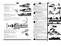
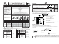
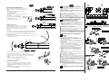
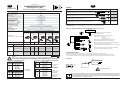
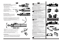
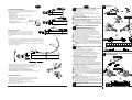
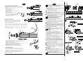
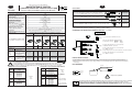
Mise en service et conseils d'utilisation
FR
FR
MINI-DETECTEUR DE POSITION
ACCESSOIRES
A COMMANDE MAGNETIQUE, MAGNETO-RESISTIF (MR)
Pour tous vérins pneumatiques prévus pour détecteurs
Série 881
Désignation
CARACTERISTIQUES GENERALES DU DETECTEUR
PUISSANCES COMMUTABLES maxi
TENSION COMMUTEE maxi
INTENSITE COMMUTEE maxi
BRANCHEMENT
CHUTE DE TENSION (EN 60.947-5-2)
6W
10 à 30 Vcc
200 mA
PNP
< 1,1 volts (I = 50 mA)
< 1,4 volts (I = 200 mA)
COURANT DE FUITE maxi
10 µA
SURTENSION ADMISSIBLE
50 volts (10 secondes)
RESISTANCE D'ISOLEMENT
1010 ohms
SENSIBILITE
3 mTesla mini (30 Gauss)
TEMPS DE REPONSE à l'ouverture
0,2 ms
à la fermeture
0,1 ms
PRECISION DE REPETITIVITE
± 0,1 mm
TEMPERATURE D'UTILISATION
- 20°C , + 70°C
PROTECTION ELECTRIQUE
Détecteur polarisé, protégé contre les courts-circuits, les surcharges (voir page suivante)
et diode de roue libre intégrée
ENVELOPPE
Boîtier thermoplastique PPS avec circuit imprimé surmoulé en résine époxy
DEGRE DE PROTECTION (CE I 529)
IP67
SIGNALISATION
Par diode (LED) verte qui s'allume lorsque la commutation est réalisée
Connecteur intégré
47
881001A max.
0m
30V-20
95
881005A max.
30V-20
0m
49
881001A max.
30V-20
0m
K
KN
PEC
P2L - P2B
2 mètres 5 mètres
30
70
Désignation
DETECTEUR UNI
type MR seul
le kit de fixation, adapté à
chaque vérin est à commander séparément, (voir
pages suivantes)
86
3
4
1
Connecteur mâle à vis Ø M8 - 3 broches
+
charge
35
_
Sortie par câble Ø 3 mm, extrémité dénudée
3 conducteurs 0,14 mm2 - Fil marron : pôle +
Fil bleu
: pôle Fil noir
: charge
161
162
163
164
165
166
VERINS ISOCLAIR Ø 32 à 63 mm
CODE
Ø Vérin
DU KIT DE FIXATION
(mm)
32
881 00 167
40
881 00 168
50
881 00 169
63
881 00 170
(383 45 35) MS-P295-2
1
charge
_
1
4
Sortie par câble Ø 3 mm avec connecteur mâle
à vis Ø M8 - 3 broches
(modèle adapté pour connecteur VCS/Valve connection système)
Sortie par câble Ø 3 mm avec connecteur mâle
à vis Ø M12 - 3 broches
+
_
881 00 192
881 00 193 881 00 194
881 00 195
881 00 593
881 00 196
PROTECTION ELECTRIQUE
• Sortie protégée contre les courts circuits éventuels de la charge lorsque le courant de sortie est inférieur ou égal à 0,2 A.
• Le branchement incorrect des fils de sortie peut entraîner le non fonctionnement ou la destruction du mini-détecteur.
• Malgré la protection interne, dans le cas de charge selfique, il est recommandé d'utiliser une diode (montée en parallèle)
sur la charge
RACCORDEMENT
ADAPTATION SUR VERIN PES A TUBE PROFILE
VERINS ISOCLAIR Ø 8 à 25 mm
CODE
Ø Vérin
DU KIT DE FIXATION
(mm)
00
00
00
00
00
00
4
charge
Recommandations d'utilisation
Pour les applications qui entrainent de grands débattements et mouvements de vérins + détecteurs,
il est impératif d'utiliser le mini-détecteur avec connecteur M8 intégré au boîtier et des allonges équipées
d'un câble (3 conducteurs) de type classe 6 prévu à cet effet. (accessoire spécifique: nous consulter)
881
881
881
881
881
881
charge
3
ADAPTATION SUR VERIN ISOCLAIR
8
10
12
16
20
25
Sortie par câble Ø 3 mm avec connecteur mâle
encliquetable Ø 8 mm - 3 broches
1
_
881 00 149
❉ Détecteur fourni avec le support de fixation (vis + écrou profilé) permettant l'adaptation directe sur vérins à rainures
!
4
5m
Détecteur UNI type MR
+ mini kit de fixation (❉)
(pour adaptation directe
sur vérins à rainures en
queue d’aronde
881 00 203
Vue coté des broches
des connecteurs mâles
3
881 00 595
881 00 202
3
CONNEXIONS DES DETECTEURS MAGNETO-RESISTIFS : 5 possibilités
0,8 m
881 00 147
3
(1) Allonge prévue pour les détecteurs a connecteur M8 intégré. L'adaptation sur connecteur mâle encliquetable Ø 8 est déconseillée.
(2) Raccordement des détecteurs, fil marron = +, fil bleu = -, fil noir = charge
+
881 00 143 881 00 145
881 00 238
CM5
CODES
881 00 141
2
4
Connecteur coudé à 90° Ø M8, orientable 90° x 90°, 3 broches femelles, IP67
+
22
881 00 239
3
1
3
6
br = 1 1
blu= 3
blk= 4 4
1
0,8 m
Masse (g)
Adaptable sur
vérin type:
CAS - CIS
CIB
PES - PES Ω
PCN
TUB
R - RS
3
4
CM5
MR
0m
MR
30V-20
MR
43
881001A max.
br = 1
blu= 3 1
blk= 4
4
Sortie câble à 45 ° protégée par un passe-fil
MR
MR
30V-20
5m
PVC
Connecteur droit Ø M8, 3 broches femelles, IP67
2/5m
41
881001
max.
0mA
PVC
Allonge par câble en PVC, longueur 5 m, 3 conducteurs 0,25 mm2
avec 1 connecteur M12 femelle vissable, l'autre extrémité nue (2)
Connecteur mâle câble PVC long. 2 ou 5 m câble PVC long. 0,8 m câble PVC long. 5 m câble PVC long. 0,8 m
3 conducteurs 0,14 mm2 + connecteur mâle + connecteur mâle + connecteur mâle
à vis Ø M8
à vis Ø M8
à vis Ø M12
extrémité dénudée
encliquetable Ø 8
3 broches
3 broches
3 broches
3 broches
RACCORDEMENT/CONNECTIQUE
(5 possibilités / 6 modèles, au choix)
CODE
5m
Allonge par câble en PVC, longueur 5 m, 3 conducteurs 0,25 mm2
avec 1 connecteur M8 femelle vissable, l'autre extrémité nue (1) (2)
Ø Vérin
(mm)
32-40
50-63
80-100
125
CODE
DU KIT DE FIXATION
881 00 153
881 00 154
881 00 155
881 00 156
Fixation
par
bride
1 (+)
● 3 (--)
●4
●
marron
1
+
bleu
3
_
noir
4
ADAPTATION SUR VERINS PES-PCN A TIRANTS
Fixation
par
collier
Ø Vérin
(mm)
(25) 32-40
50-63
80
100
125
160
200
CODE
DU KIT DE FIXATION
881 00 150
881 00 151
881 00 152
881 00 157
881 00 158
881 00 159
881 00 160
Ø 32 à 80 mm:
Fixation par bride
Ø 100 à 200 mm:
Fixation par collier
!
charge
Respecter les polarités
Conformément à la directive CEE 89/392/CEE Annexe II B, une Déclaration d’incorporation peut être fournie sur demande.
Veuillez nous indiquer le numéro d’accusé de réception (AR) et les références ou codes des produits concernés.
Ce produit est conforme aux exigences essentielles de la Directive 89/336/CEE sur la Compatibilité Electromagnétique,
et amendements. Une déclaration de conformité peut être fournie sur simple demande.
2
FR
FR
A ISOCLAIR
1 - Placer le détecteur sur le collier de fixation
2 - Engager la vis dans le détecteur et serrer l'ensemble
3 - Ouvrir le collier
4 - Placer l'ensemble détecteur + collier autour du tube
5 - Positionner l'ensemble détecteur + collier au point de
détection souhaité
6 - Bloquer l'ensemble sur le vérin
I Possibilité de montage des détecteurs magnétiques pour
contrôle de positions intermédiaires.
II Possibilité de montage des détecteurs avec sortie électrique
dirigée vers les fonds du vérin en retournant de 180° l'ensemble détecteur + collier de fixation
III Pour contrôler les positions situées aux extrémités maximales
du vérin, les détecteurs avec connecteurs mâles intégrés
doivent être montés avec les connecteurs orientés vers le
centre du vérin
S'assurer que le câble électrique d'alimentation du détecteur
n'est pas soumis à des tractions/torsions néfastes à sa durée
de vie.
- Eviter les câbles trop courts
- Ne pas tirer sur les câbles
- Ne pas plier les câbles
- Respecter un rayon de courbure de 15 mm mini.
en montage statique
- Ne pas écraser les câbles
notamment lors d'utilisation
de pince à collier serre-câble.
A régler impérativement
sur serrage mini (pour câble Ø 2 - 2,5 mm).
15 mm min.
r.
Vers partie fixe
Pour les applications qui entrainent de grands débattements ou importants
déplacements du vérin + détecteur, il est impératif d'utiliser le mini-détecteur
avec connecteur M8 intégré au boîtier (X) et des allonges (Y) avec un câble de
type classe 6 prévu à cet effet.
- Lier le câble au vérin comme ci-contre et respecter un rayon de courbure
de 120 mm mini.
(X)
(Y)
120
mm
4 x 0,8
C. max: 0,4 N.m
C. max: 0,4 N.m
3
4 x 0,8
6
4
B MONTAGE SUR VERIN PES
A TUBE PROFILE Ø 32 à 125:
Applications mobiles:
Lors de montage dynamique, le câble subit des
mouvements de balancier dus à la masse des
connecteurs ou à un excés de longueur de câble qui
peuvent provoquer sa rupture. Il est donc nécessaire
de lier les connecteurs au vérin.
2
mi n
.
1- Placer le détecteur sur le kit de fixation
2- Engager la vis dans le détecteur et serrer l'ensemble
3- Placer l'ensemble sur l'un des 4 bossages et les
positionner au point de détection souhaité
4- S'assurer que le détecteur est en contact avec le tube
et bloquer l'ensemble sur le vérin (clé six pans 2 mm)
I Possibilité de montage des détecteurs magnétiques pour
contrôle de positions intermédiaires.
II Possibilité de montage des détecteurs avec sortie électrique
dirigée vers l'arrière du vérin en adaptant le détecteur + la
bride de fixation.
III Pour contrôler les positions situées aux extrémité maximales
du vérin, les détecteurs avec connecteurs mâles intégrés
doivent être montés avec les connecteurs orientés vers le
centre du vérin
Possibilité
de montage des détecteurs sur n'importe lequel
IV
des 4 bossages.
C MONTAGE SUR VERINS PES-PCN A TIRANTS
Ø 32 à 80 mm :
1- Placer le détecteur sur le kit de fixation
2- Engager la vis dans le détecteur et serrer l'ensemble
3- Placer l'ensemble sur l'un des 4 tirants et le positionner au
point de détection souhaité
4- S'assurer que le détecteur est en contact avec le tube et
bloquer l'ensemble sur le vérin (clé six pans 3 mm)
5
II
I
15
❉
D
min.
Led
1
A MONTAGE SUR VERIN ISOCLAIR Ø 8 à 63:
RECOMMANDATIONS DE MONTAGE
21
Ø
cylinder
D
E
8
28
13
E
10
29
14
12
30
15
16
32
17
20
34
19
25
36
21
32
41
26
- Eviter le montage des détecteurs de positions à proximité de
toute présence ferromagnétique ou électromagnétique intense
(bobine, pince à soudage).
- Ne pas utiliser en environnement d'huiles ou solvants
incompatibles avec le câble en PVC (si nécessaire, nous consulter).
Nettoyage avec solution alcaline (eau savonneuse).
Raccordement des détecteurs à connecteur intégré:
- Serrage manuel du connecteur (Ne pas utiliser d'outil)
MISE EN SERVICE
- S'assurer que les détecteurs UNI fonctionnent dans la limite
des plages d'utilisation (électrique, mécanique, température)
définies dans cette documentation. Tout dépassement peut
entraîner la détérioration des détecteurs
- Aucune modification ne peut être réalisée sur le matériel sans
notre accord préalable.
D MONTAGE SUR VERINS K, KN, PEC P2L/P2B
voir ci-contre
3
4
50
51
36
63
57
42
III
B PES A TUBE PROFILE - PES WITH PROFILED BARREL
PES MIT PROFILROHR
Ø 100 à 200 mm :
1- Placer le collier autour du tube (sous les tirants) en
positionnant les 2 extrémités coté serrage
2- Desserrer la bride de façon à assurer une course de serrage
suffisante (ne pas dévisser la vis de son support)
3- Placer le détecteur sur le support en plastique
4- Engager la vis dans le support et serrer l'ensemble
5- Placer les extrémités du collier dans les encoches de la bride
6- Glisser le détecteur avec son support sous le collier
7- Positionner l'ensemble détecteur + collier au point de détection
8- S'assurer que le détecteur est en contact avec le tube et
bloquer l'ensemble sur le vérin
I Possibilité de montage des détecteurs magnétiques pour
contrôle de positions intermédiaires.
II Possibilité de montage des détecteurs avec sortie électrique
dirigée vers l'arrière du vérin Ø 32 à 80 mm
III Pour contrôler les positions situées aux extrémité maximales
du vérin, les détecteurs avec connecteurs mâles intégrés
doivent être montés avec les connecteurs orientés vers le
centre du vérin
IV Ø 32 à 80 mm
Possibilité de montage des détecteurs sur n'importe lequel
des 4 tirants.
100 à 200 mm (fixation par collier)
V Ø
Possibilité de montage des détecteurs avec sortie électrique
dirigée vers l'arrière du vérin Ø 100 à 200 mm en retournant
l'ensemble support + détecteur de 180° après avoir desserrer
(sans l'enlever) le collier.
40
46
31
C. max: 0,4 N.m
2
1
4 x 0,8
3
C. max: 0,9 N.m
2
I
21
*
4
Installation and operation
GB
GB
MINIATURE MAGNETIC POSITION DETECTORS
ACCESSORIES
MAGNETO-RESISTANT TYPE (MR)
for air cylinders equipped for magnetic position detectors
Series 881
Description
Extension consisting of PVC, length 5 m, 3 wire conductors 0.25
with 1 screw-on femal M8 connector (other end plain) (1) (2)
DETECTOR CHARACTERISTICS
MAX. SWITCHING POWER
MAX. SWITCHING VOLTAGE
MAX. SWITCHING CURRENT
CONNECTION
VOLTAGE DROP ((EN 60.947-5-2))
6W
10 to 30 V DC
200 mA
PNP
< 1.1 Volt (I = 50 mA)
< 1.4 Volt (I = 200 mA)
10 µA
50 Volt (10 seconds)
1010 ohm
min. 3 mTesla (30 Gauss)
0.2 ms
0.1 ms
± 0,1 mm
-20 °C , +70 °C
Polarized detector, protectec against short-circuits and overloads
and incorporated recovery diode
Thermoplastic housing (PPS) with epoxy resin encapsulated printed circuit
IP67
Green diode (LED) which lights up during switching
MAX: LEAKAGE CURRENT
MAX. ALLOWABLE OVERVOLTAGE
INSULATION RESISTANCE
SENSITIVITY
RESPONSE TIME
opening
closing
REPEATABILITY
WORKING TEMPERATURE
PROTECTION ELECTRIQUE
HOUSING
DEGREE OF PROTECTION (CE I 529)
SIGNAL INDICATION
CODE
5m
mm2
br = 1
blu= 3 1
blk= 4
PVC
5m
Extension consisting of PVC, length 5 m, 3 wire conductors 0.25 mm2
with 1 screw-on femal M12 connector (other end plain) (2)
br = 1 1
blu= 3
blk= 4 4
PVC
881 00 239
2
881 00 238
3
3
1
Straiht 3-pin female connector Ø M8, IP67
3
4
CM5
881 00 202
4
3
1
4
Right angle 3-pin female connector Ø M8, orientable 90° x 90°, IP67
881 00 203
CM5
(1) Extension for integral M8 connector detectors. Coupling to snap-on Ø 8 male connectors is not advised.
(2) Detector connection, brown wire = +, blue wire = -, black wire = load
CONNECTION OF MAGNETORESISTANT DETECTORS: 5 possibilities
View from male contact
side of connector
Integrated connector
0m
30V-20
95
881005A max.
30V-20
0m
49
881001A max.
30V-20
0m
3
4
3-pin screw-type male connector Ø M8 - 3 pins
1
+
load
_
2/5m
MR
0m
30V-20
47
881001A max.
MR
30V-20
43
881001A max.
MR
41
881001
max.
0mA
MR
CONNECTION
(5 possibilities / 6 types at choice)
MR
45° lead outlet protected by feed-through sleeve
5 m PVC lead
3-pin screw-type PVC lead, 2 or 5 m long, 0.8 m PVC lead
0.8 m PVC lead
3 wires 0.14 mm2,
+ 3-pin plug-in + 3-pin screw-type + 3-pin screw-type
male connector,
stripped ends
male connector, male connector, male connector,
Ø M8
Ø M8
Ø8
Ø M12
Lead outlet Ø 3 mm, stripped ends
3 wires 0,14 mm2 - Brown wire = +
Blue wire = Black wire = load
Lead outlet Ø 3 mm with 3-pin plug-in
male connector Ø 8 mm - 3 pins
0,8 m
3
4
1
+
Weight (g)
6
Compatible
cylinders
CAS - CIS
CIB
PES - PES Ω
TUB
R - RS
K
KN
PEC
P2L - P2B
2 metres 5 metres
30
70
Description
UNI Magneto-resistive
detector only
The mounting kit for
each cylinder is to be
ordered separately (see
following pages).
UNI Magneto-resistive
detector + mounting kit (❉)
(for direct mounting on
cylinders with swallow
tail grooves)
load
_
5m
22
86
35
3
4
Lead outlet Ø 3 mm with 3-pin screw-type
male connector Ø M8
(Version adapted for VCS connector/Valve connection system)
1
+
CODES
_load
0,8 m
3
881 00 141
881 00 143 881 00 145
881 00 147
881 00 595
881 00 149
881 00 192
881 00 193 881 00 194
881 00 195
881 00 593
881 00 196
1
4
Lead outlet Ø 3 mm with 3-pin screw-type
male connector Ø M12
load
+
_
ELECTRICAL PROTECTION
• Output protected against short-circuit as long as the output current is restricted to 0.2 A.
• Improper wire connection may prevent the detector from operating or even destroy it.
• It is recommended to install a protection diode (mounted in parallel) on an inductive load in spite of the internal protection.
❉ Detector supplied with mounting kit (special nut + screw) for direct fitting to cylinder grooves
!
Recommendation for application
For cylinder + detector applications with long travels and large movements you must use the mini-detector
with M8 connector integrated in the housing and lead outlets equipped with a (3-wire) class 6 type cable especially
intended for this purpose (specific accessory: consult us).
ADAPTATION ON ISOCLAIR CYLINDER
MOUNTING ON PES CYLINDER WITH PROFILED BARREL
ISOCLAIR CYLINDERS Ø 8 to 25 mm
Ø Cylinder
CODE
FASTENING KIT
(mm)
8
10
12
16
20
25
881
881
881
881
881
881
00
00
00
00
00
00
161
162
163
164
165
166
ISOCLAIR CYLINDERS Ø 32 to 63 mm
CODE
Ø Cylinder
FASTENING KIT
(mm)
32
881 00 167
40
881 00 168
50
881 00 169
63
881 00 170
CONNECTION
Ø Cylinder
(mm)
32-40
50-63
80-100
125
CODE
FASTENING KIT
881 00 153
881 00 154
881 00 155
881 00 156
1 (+)
3 (--)
●4
●
Flange
mounting
Ø Cylinder
(mm)
32-40
50-63
80
100
125
160
200
5
00
00
00
00
00
00
00
150
151
152
157
158
159
160
+
3
_
black
4
!
CODE
FASTENING KIT
881
881
881
881
881
881
881
1
blue
load
●
MOUNTING ON PES CYLINDERS WITH TIE RODS
Collar
mounting
brown
Polarities to be observed
Ø 32 to 80 mm:
Flange mounting
Ø 100 to 200 mm:
Collar mounting
A separate Declaration of Incorporation relating to EEC-Directive 89/392/EEC Annex II B is available on request. Please
provide acknowledgement number and serial numbers of products concerned.
This product complies with the essential requirements of the EMC-Directive 89/336/EEC and amendments. A separate
Declaration of Conformity is available on request.
6
GB
GB
II
IV
A MOUNTING ON ISOCLAIR CYLINDER Ø 8 to 63:
MOUNTING RECOMMENDATIONS
1 - Put the detector in place, on collar
2 - Introduce the screw into the detector and tighten the unit.
3 - Open the collar.
4 - Place the unit detector + collar around the barrel.
5 - Position the detector + collar unit at the desired point of detection.
6 - Tighten the unit on the cylinder.
I It is possible to mount additional magnetic detectors
for intermediate position indication.
II In order to fasten the detector with its electric outlet to the
rear rotate the unit detector + collar by 180°.
III In order to be able to control the max. end of travel of the cylinder,
the detectors with integrated male connectors must be mounted
with the connectors facing towards the centre of the cylinder.
Make sure that the power cable for the detector is not
subject to tension or torsional stress throughout its
lifetime.
- Avoid using cables which are not long enough.
- Do not pull on the cables.
- Do not fold the cables.
- Observe a minimum bending radius of 15 mm in static
assembly.
- Do not pinch the cables when using
a retaining ring plier. The minimum
tightening torque must be observed
(for cable dia. 2 – 2.5 mm).
B MOUNTING ON PES CYLINDER WITH
min.
r.
15 mm min.
Flexible applications:
In dynamic assembly the cable is subject to oscillating
movements due to the weight of the connectors or
excess cable lengths which may cause the cable to
break. The connectors must therefore be connected to
the cylinder.
To the fixed part
For cylinder + detector applications with long travels and large movements you
must use the mini-detector with M8 connector integrated in the housing (X)
and lead outlets equipped with a (2- or 3-wire) class 6 type cable (Y) especially
intended for this purpose.
- Connect the cable to the cylinder as shown opposite and observe a minimum
bending radius of 120 mm.
(X)
(Y)
120
PROFILED BARREL Ø 32 to 125:
1- Put the detector in place, on the mounting kit
2- Introduce the screw into the detector and tighten the unit.
3- Place the unit on one of the bosses and position it at the
desired point of detection.
4- Make sure that the detector is in contact with the barrel and
tighten the unit on the cylinder (use a 2 mm hexagon wrench).
I It is possible to mount additional magnetic detectors
F
for intermediate position indication.
II In order to fasten the detector with its electric outlet to the rear,
mount the detector + the mounting bracket.
III In order to be able to control the max. end of travel of the cylinder,
the detectors with integrated male connectors must be mounted
with the connectors facing towards the centre of the cylinder.
IV The detectors can be mounted on any one of the 4 bosses.
E max.
D
E max.
Ø
cylinder
D
E
32
40
50
63
80
100
125
27
42
31
45
36
51
41
55
47
64
58
71
69
82
III
C PES - PCN / TIRANTS - TIE RODS - ZUGANKERN
C. max: 0,4 N.m
2
1
Ø 32 ... 80 mm
4 x 0,8
C MOUNTING ON PES CYLINDER WITH
mm
TIE RODS
mi n
Ø 32 to 80 mm :
.
1- Put the detector in place, on the mounting kit
2- Introduce the screw into the detector and tighten the unit.
3- Place the unit on one of the tie rods and position it at the
desired point of detection.
4- Make sure that the detector is in contact with the barrel and
tighten the unit on the cylinder (use a 3 mm hexagon wrench).
3
C. max: 1,6 N.m
4
3
Ø 100 à 200 mm :
- Do not mount position detectors near to ferromagnetic or intense
electromagnetic fields (solenoid coil, soldering tongs etc.).
- Do not use the PVC cable in oily environments or with incompatible
solvents (consult us if necessary). Clean with an alcaline solution (soapy
water).
Assembly of detector with integrated connector:
- Tighten the connector by hand (do not use any tools).
PUTTING INTO SERVICE
- Observe the maximum/minimum (electrical, mechanical,
temperature) operating ranges defined for the UNI detectors in
this documentation. Any non-compliance may cause the detectors
to deteriorate.
- All modifications to the equipment shall be subject to the prior
approval of ASCO/JOUCOMATIC.
7
1- Place the collar around the barrel (underneath the tie rods).
Position the 2 ends towards the fastening side.
2- Loosen the flange so that you have enough allowance for
tightening (do not remove the screw from the support).
3- Place the detector on its plastic support.
4- Introduce the screw into the support and tighten the unit.
5- Introduce the collar ends into the flange openings.
6- Slip the detector together with its support underneath the
collar.
7- Position the detector + collar unit at the desired point of
detection.
8- Make sure that the detector is in contact with the barrel and
tighten the unit on the cylinder.
I It is possible to mount additional magnetic detectors
for intermediate position indication.
II Is is possible to mount the detectors with their electrical outlet
facing towards the rear of the cylinder diameters 32 to 80 mm.
III In order to be able to control the max. end of travel of the cylinder,
the detectors with integrated male connectors must be mounted
with the connectors facing towards the centre of the cylinder.
IV Ø 32 to 80 mm
The detectors can be mounted on any one of the 4 tie rods.
100 to 200 mm (collar mounting)
V Ø
In order to fasten the detector on cylinder diameters 100 to
200 mm with its electrical outlet to the rear, rotate the support + detector by 180° after having loosened the collar (do
not remove it).
1
Ø 100 ... 200 mm
C. max: 0,4 N.m
4
6,5 x 1,2
6
7
8
C. max: 1,6 N.m
5
8
4 x 0,8
2
D MOUNTING ON K, KN, PEC, P2L/P2B CYLINDERS
see opposite
3
Inbetriebnahme
DE
DE
MINI-NÄHERUNGSSCHALTER
Baureihe 881
ZUBEHÖR
MAGNETORESISTIV (MR)
Für Pneumatik-Zylinder mit Magnetkolben
Bezeichnung
ELEKTRISCHE DATEN
41
881001A max.
0m
30V-20
43
881001A max.
30V-20
0m
47
881001A max.
30V-20
0m
95
881005A max.
30V-20
0m
49
881001A max.
30V-20
0m
2m
30
Zylindertyp:
Bezeichnung
CAS - CIS
CIB
PES - PES Ω
TUB
R - RS
UNI-Naherungsschalter
mit MR allein.
Der für jeden Zylinder bestimmte Befestigungssatz
ist separat zu bestellen
(siehe folgende Seiten).
881 00 141
K
KN
PEC
P2L - P2B
UNI-Naherungsschalter mit MR
+ Mini-Befestigungssatz (❉)
(für die direkte Montage in die
schwalbenschwanzförmigen
Nuten der Zylinder).
881 00 192
22
86
881 00 195
3
4
_
2/5m
Last
Kabelschwanz Ø 3 mm mit abisolierten Enden,
3adrig 0,14 mm2 - Litze braun = +
Litze blau
=Litze schwarz = Last
ISOCLAIR-ZYLINDER Ø 8 bis 25 mm
Ø Zylinder
BESTELL-CODE
(mm)
BEFESTIGUNGSSATZ
8
881 00 161
10
881 00 162
12
881 00 163
16
881 00 164
20
881 00 165
25
881 00 166
ISOCLAIR-ZYLINDER Ø 32 bis 63 mm
Ø Zylinder
BESTELL-CODE
(mm)
BEFESTIGUNGSSATZ
32
881 00 167
40
881 00 168
50
881 00 169
63
881 00 170
4
Kabelschwanz Ø 3 mm mit 3poligem Leitungsstecker
Ø 8 mm mit Rastverschluß (3 Pole angeschlossen)
1
_
5m
881 00 149
4
Last
Kabelschwanz Ø 3 mm mit 3poligem Leitungsstecker Ø M8 mit
Schraubverschluß (3 Pole angeschlossen)
1
_
3
881 00 196
BESTELL-CODE
BEFESTIGUNGSSATZ
881 00 153
881 00 154
881 00 155
881 00 156
Befestigung mit
Bügel
Last
Kabelschwanz Ø 3 mm mit 3poligem Leitungsstecker Ø M12
mit Schraubverschluß (3 Pole angeschlossen)
1
4
Last
SCHUTZBESCHALTUNG
ANSCHLUSS
1 (+)
3 (--)
●4
●
braun
1
+
blau
3
_
schwarz
4
Ø Zylinder
(mm)
32-40
50-63
80
100
125
160
200
9
BESTELL-CODE
BEFESTIGUNGSSATZ
881 00 150
881 00 151
881 00 152
881 00 157
881 00 158
881 00 159
881 00 160
Last
●
MONTAGE AUF PES-ZYLINDER MIT ZUGANKERN
Befestigung mit
Klemmband
(Version auf VCS-Stecker abgestimmt/Valve connection system)
• Der Ausgang ist gegen Kurzschluß geschützt, solange der Ausgangsstrom auf 0,2 A beschränkt wird.
• Unsachgemäßer elektrischer Anschluß verursacht eine Fehlfunktion des Näherungsschalters oder kann diesen zerstören.
• Trotz des internen Schutzes ist bei Anschluß einer induktiven Last eine Schutzdiode parallel zur induktiven Last zu legen.
MONTAGE AUF PES-ZYLINDER MIT PROFILROHR
Ø Zylinder
(mm)
32-40
50-63
80-100
125
881 00 203
3poliger Einbaustecker mit Gewinde Ø M8
(3 Pole angeschlossen)
1
+
35
Hinweis:
Bei Anwendungen, in denen die Zylinder + Näherungsschalter großen Hüben und Bewegungen ausgesetzt
werden, sind die zu diesem Zweck vorgesehenen Mini-Näherungsschalter mit M8-Einbausteckern sowie die mit einem
(3-adrigen) Verlängerungskabel der Klasse 6 ausgestatteten Leitungsdosen zu verwenden (Sonderzubehör: auf Anfrage).
MONTAGE AUF ISOCLAIR-ZYLINDER
3
4
Ansicht auf
Steckerseite
❉ Näherungssschalter mit Befestigungen (Schraube + Profilmutter) für die direkte Montage in die Nuten der Zylinder
!
881 00 202
ANSCHLUSS DER MAGNETORESISTIVEN NÄHERUNGSSCHALTER: 5 Möglichkeiten
+
881 00 593
3
(1) Verlängerungskabel für Näherungsschalter mit Einbaustecker M8. Die Montage auf Leitungsstecker mit Rastverschluß Ø 8 wird
nicht empfohlen.
(2) Anschluß der Näherungsschalter: braune Litze = +, blaue Litze = -, schwarze Litze = Last
+
_
881 00 193 881 00 194
881 00 238
CM5
3
881 00 595
2
3
1
0,8 m
881 00 147
br = 1 1
blu= 3
blk= 4 4
Winkelleitungsdose CØ M8, um 90° umsetzbar, 3-polig, IP67
BESTELL-CODE
881 00 143 881 00 145
881 00 239
4
+
5m
70
3
4
1
3
6
br = 1
blu= 3 1
blk= 4
CM5
0,8 m
Gewicht (g)
5m
PVC
Gerade Leitungsdose Ø M8, 3-polig, IP67
MR
ANSCHLUSS
(5 Möglichkeiten / wahlweise 6 Arten)
PVC
Verlängerungskabel aus PVC, 5 m lang, 3adrig 0,25 mm2, mit 1
Leitungsdose M12 mit Schraubverschluß (anderes Ende abisoliert) (2)
Kabelschwanz 2 oder Kabelschwanz 0,8 m Kabelschwanz 5 m Kabelschwanz 0,8 m
5 m aus PVC, 3adrig, aus PVC + 3-poliger aus PVC + 3-poliger aus PVC + 3-poliger
0,14 mm2, Enden
Leitungsstecker Ø 8 Leitungsstecker Ø M8 Leitungsstecker Ø M12
abisoliert
mit Rastverschluss mit Schraubverschluss mit Schraubverschluss
MR
3poliger Einbaustecker mit
Gewinde, Ø M8
MR
GEHÄUSE
SCHUTZART (CE I 529)
SIGNALANZEIGE
MR
MAX. VERLUSTSTROM
ZUL. ÜBERSPANNUNG
ISOLATIONSWIDERSTAND
EMPFINDLICHKEIT
ANSPRECHZEIT
Öffnen
Schließen
WIEDERHOLGENAUIGKEIT
BETRIEBSTEMPERATUR
SCHUTZBESCHALTUNG
6W
10 bis 30 V DC
200 mA
PNP
< 1,1 Volt (I = 50 mA)
< 1,4 Volt (I = 200 mA)
10 µA
50 Volt (10 Sekunden)
1010 Ω
min. 3 mTesla (30 Gauss)
0,2 ms
0,1 ms
± 0,1 mm
-20 °C bis 70 °C
Polarisierter Näherungsschalter, gegen Kurzschluß und
Überlast geschützt (siehe nächste Seite), Freilaufdiode
Thermoplastisches Gehäuse (PPS) mit epoxydharzumspritzter gedruckter Schaltung
IP67
Leuchtdiode (LED grün), leuchtet auf, sobald der Kontakt geschlossen ist.
Einbaustecker
Kabelausgang um 45° abgewinkelt mit Kabeltülle
MR
MAX. SCHALTLEISTUNG
MAX. SCHALTSPANNUNG
MAX. SCHALTSTROM
ANSCHLUSS
SPANNUNGSABFALL (EN 60.947-5-2)
BESTELL-CODE
5m
Verlängerungskabel aus PVC, 5 m lang, 3adrig 0,25 mm2, mit 1
Leitungsdose M8 mit Schraubverschluß (anderes Ende abisoliert) (1) (2)
!
Bitte Polarität beachten:
Ø 32 bis 80 mm:
Befestigung mit
Klemmbacken
Ø 100 bis 200 mm:
Befestigung mit
Klemmband
Eine separate Herstellererklärung im Sinne der Richtlinie 89/392/EWG Anhang II B kann bei Bedarf unter Angabe der
Auftragsbestätigungsnummer und der Bezeichnung oder des Bestell-Codes des betreffenden Produkts angefordert werden.
Dieses Produkt entspricht der Richtlinie 89/336/EWG und Ergänzungen über die Elektromagnetische Verträglichkeit. Eine
Konformitätsbescheinigung ist auf Anfrage erhältlich.
10
I
DE
DE
A MONTAGE AUF ISOCLAIR-ZYLINDER Ø 8 bis 63:
MONTAGE-EMPFEHLUNGEN
Achten Sie darauf, dass das Spannungsversorgungskabel des
Näherungsschalters während der gesamten Lebensdauer ohne
Zugbelastung verlegt und nicht verdreht wird.
- Kabel ausreichend lang dimensionieren.
- Nicht an den Kabeln ziehen.
- Die Kabel nicht knicken.
- Bei einer statischen Montage ist ein Biegeradius von mindestens 15 mm zu beachten.
- Darauf achten, dass die Kabel
insbesondere bei der Verwendung von
Zangen zur Montage des Klemmbands
nicht gequetscht werden.
Der Mindestanziehmoment
min.
(bei Kabel Ø 2 - 2,5 mm) ist unbedingt zu beachten.
21
IV
PROFILROHR Ø 32 bis 125 :
r.
15 mm min.
Zum festen Teil
Bei Anwendungen, in denen die Zylinder + Näherungsschalter großen Hüben
und Bewegungen ausgesetzt sind, sind die zu diesem Zweck vorgesehenen
Mini-Näherungsschalter mit M8-Einbausteckern (X) sowie die mit einem (2oder 3-adrigen) Verlängerungskabel der Klasse 6 ausgestatteten
Leitungsdosen (Y) zu verwenden [Sonderzubehör (auf Anfrage)].
- Kabel wie in nebenstehender Zeichnung verbinden und auf einen Biegeradius
von mindestens 120 mm achten.
(Y)
120
mm
1- Bügel auf den Näherungsschalter stecken.
2- Schraube in den Näherungsschalter eindrehen.
3- Einheit auf eine der vier Buckeln montieren und am Abtastpunkt positionieren.
4- Der Näherungsschalter muß auf dem Rohr aufliegen,
anschließend die Einheit festziehen. (Inbusschlüssel 2 mm)
I Möglichkeit der Befestigung von Näherungsschaltern zur
Überwachung der Zwischenpositionen
II Zur Montage des Näherungsschalters mit elektrischem Anschluß hinten ist der Näherungsschalter und der
Befestigungsbügel wie unten angegeben.
Kontrolle der Positionen an den Enden des Zylinders müssen
III Zur
die Näherungsschalter mit Einbaustecker so montiert werden,
daß die Einbaustecker zur Zylindermitte ausgerichtet sind.
IV Die Näherungsschalter können auf einen der vier Buckel
montiert werden.
.
;;;;;;;;;
;;;;;;;;;
;;;;;;;;;
;;;;;;;;;
;;;;;;;;;
;;;;;;;;;
;;;;;;;;;
;;;;;;;;;
;;;;;;;;;
D
II
E max.
;;;;;;;;;;
;;;;;;;;;;
;;;;;;;;;;
;;;;;;;;;;
;;;;;;;;;;
;;;;;;;;;;
;;;;;;;;;;
;;;;;;;;;;
;;;;;;;;;;
;;;;;;;;;;
;;;;;;;;;
;;;;;;;;;
;;;;;;;;;
;;;;;;;;;
;;;;;;;;;
;;;;;;;;;
;;;;;;;;;
;;;;;;;;;
;;;;;;;;;
;;;;;;;;;
Ø cylinder
D
E
C MONTAGE AUF PES-PIS ZYLINDER MIT
ZUGANKERN
mi n
E max.
E max.
E max.
Bei einer dynamischen Montage ist das Kabel aufgrund
des Gewichts der Leitungsdosen oder eines zu langen
Kabels Schwingungen ausgesetzt, die zu einem Bruch
des Kabels führen können. Die Leitungsdosen sind
deshalb an den Zylinder zu montieren.
V
;;;;;;;;;
;;;;;;;;;
;;;;;;;;;
;;;;;;;;;
;;;;;;;;;
;;;;;;;;;
;;;;;;;;;
;;;;;;;;;
;;;;;;;;;
B MONTAGE AUF PES-ZYLINDER MIT
Mobile Anwendungen:
(X)
*
1- Näherungsschalter auf das Klemmband stecken.
2- Schraube in den Näherungsschalter eindrehen und festziehen.
3- Klemmband öffnen.
4- Einheit aus Näherungsschalter und Klemmband um das Rohr legen.
5- Einheit am Abtastpunkt positionieren.
6- Einheit auf dem Zylinder festziehen.
I Möglichkeit der Befestigung von Näherungsschaltern zur
Überwachung der Zwischenstellungen.
II Zur Montage des Näherungsschalters mit elektrischem
Anschluß hinten ist die Einheit aus Näherungsschalter und
Klemmband um 180° zu drehen.
III Zur Kontrolle der Positionen an den Enden des Zylinders müssen
die Näherungsschalter mit Einbaustecker so montiert werden,
daß die Einbaustecker zur Zylindermitte ausgerichtet sind.
32
30
44
40
34
47
50
42
51
63
47
56
80
55
63
100 125 160 200
75 88 106 127
Ø 32 bis 80 mm :
1- Näherungsschalter auf die Klemmbacke stecken.
2- Schraube in den Näherungsschalter eindrehen und festziehen.
3- Einheit auf einen der 4 Zuganker montieren und am
Abtastpunkt positionieren.
4- Der Näherungsschalter muß auf dem Rohr aufliegen,
anschließend die Einheit festziehen. (Inbusschlüssel 3 mm)
III
Ø 100 bis 200 mm :
- Näherungsschalter nicht neben intensiven ferromagnetischen oder
elektromagnetischen Störquellen (Magnetspulen, Schweißzangen)
montieren.
- Kabel aus PVC nicht in öligen Umgebungen oder mit inkompatiblen
Lösungsmitteln verwenden (Wir bitten ggf. um Rücksprache).
Reinigung mit einem alkalischen Mittel durchführen (Seifenwasser).
Anschluss der Näherungsschalter mit Einbaustecker:
- Näherungsschalter von Hand festziehen (Kein Werkzeug verwenden!)
1- Klemmband um das Rohr legen (unter den Zugankern). Die
zwei Enden müssen sich auf der Seite befinden, auf der sie
festgezogen werden sollen.
2- Klemmband lösen, jedoch nicht entfernen (die Schraube nicht
von der Halterung lösen).
3- Näherungsschalter auf die Kunststoffhalterung stecken.
4- Festschrauben.
5- Enden des Klemmbandes in die Aussparungen einlegen.
6- Näherungsschalter mit der Halterung unter das Klemmband schieben.
7- Einheit aus Näherungsschalter umd Klemmband am
Abtastpunkt positionieren.
8- Der Näherungsschalter muß auf dem Rohr aufliegen,
anschließend die Einheit festziehen.
I Möglichkeit der Befestigung von Näherungsschaltern zur
Überwachung der Zwischenpositionen.
II Zur Montage des Näherungsschalters auf Zylinderdurchmesser 32 bis 80 mm mit elektrischem Anschluß hinten ist der
Näherungsschalter wie unten angegeben
III Zur Kontrolle der Positionen an den Enden des Zylinders müssen
die Näherungsschalter mit Einbaustecker so montiert werden,
daß die Einbaustecker zur Zylindermitte ausgerichtet sind.
IV
INBETRIEBNAHME
- Die Näherungsschalter des Typs UNI müssen immer in Übereinstimmung mit
den in dieser Unterlage angegebenen technischen Daten (elektrische und
mechanische Kenndaten, Temperatur) verwendet werden. Jegliche
Nichteinhaltung kann zu einer Beschädigung der Näherungsschalter führen.
- Änderungen bedürfen der vorherigen Zustimmung von ASCO/JOUCOMATIC.
V
Die Näherungsschalter können auf einen der vier Zuganker
montiert werden.
Ø 100 bis 200 mm (Befestigung mit Klemmband)
Zur Montage des Näherungsschalters auf Zylinderdurchmesser
100 bis 200 mm mit elektrischem Anschluß hinten ist die Stütze
und der Näherungsschalter nach dem Lösen des Klemmbandes um 180° zu drehen (Klemmband nicht entfernen).
D MONTAGE AUF K, KN, PEC, P2L/P2B-ZYLINDER
12
C. max: 0,4 N.m
1
3
2
N°1
2
1
3
Ø 32 bis 80 mm
siehe nebenstehende Zeichnung
11
D TYPE K, KN, PEC, P2L/P2B
l
Messa in servizio e istruzioni d'impiego
IT
IT
FINE CORSA MAGNETICI MINIATURIZZATI
ACCESSORI
DI TIPO MAGNETORESISTIVO (MR)
Per cilindri peumatici previsti per fine corsa
Serie 881
Descrizione
CARATTERISTICHE GENERALI DEL FINE CORSA
POTENZE COMMUTABILI max
TENSIONE COMMUTATA max
INTENSITA' COMMUTATA max
COLLEGAMENTO
CADUTA DI TENSIONE (EN 60.947-5-2)
6W
da 10 a 30 V CC
200 mA
PNP
< 1,1 volt (I = 50 mA)
< 1,4 volt (I = 200 mA)
CORRENTE DI DISPERSIONE max
10 µA
SOVRATENSIONE AMMESSA
50 volt (10 secondi)
RESISTENZA DI ISOLAMENTO
1010 ohm
SENSIBILITA'
3 mTesla min (30 Gauss)
TEMPO DI RISPOSTA all'apertura
0,2 ms
alla chiusura
0,1 ms
PRECISIONE DI RIPETITIVITA'
± 0,1 mm
TEMPERATURA AMMESSA
- 20°C , + 70°C
PROTEZIONE ELETTRICA
fine corsa polarizzato, protetto contro i corto circuiti, i sovraccarichi
e diodo integrato
CUSTODIA
contenitore in polimero PPS con circuito stampato incapsulato in resina epossidica
GRADO DI PROTEZIONE (CE I 529)
IP67
SEGNALAZIONE
mediante diodo (LED) verde che si illumina quando il contatto è chiuso
Uscita cavo a 45 ° protetta mediante passacavo
Connettore integrato
30V-20
0m
49
881001A max.
30V-20
0m
Peso (g)
Montaggio su
cilindri tipo:
CAS - CIS
CIB
PES - PES Ω
TUB
R - RS
K
KN
PEC
P2L - P2B
6
Descrizione
Solo FINE CORSA UNI
tipo MR
il kit di fissaggio, adatto a
qualsiasi cilindro, deve essere ordinato separatamente,
(vedere pagine seguenti)
86
881 00 192
881 00 193 881 00 194
881 00 195
881 00 593
881 00 196
3
4
Connettore maschio a vite Ø M8 - 3 poli
1
+
_
2/5m
carico
Uscita cavo Ø 3 mm, estremità nude
3 conduttori 0,14 mm2 - Filo marrone = polo +
Filo blu = polo Filo nero = carico
Uscita cavo Ø 3 mm con connettore maschio a
scatto Ø 8 mm - 3 poli
0,8 m
4
1
Istruzioni per l'uso
Per le applicazioni che comportano grandi oscillazioni e movimenti dei cilindri e dei fine corsa,
è necessario utilizzare il fine corsa miniaturizzato con connettore M8 integrato alla custodia e delle prolunghe
provviste di un cavo (3 conduttori) del tipo classe 6 previsto allo scopo. (accessorio specifico: consultarci)
MONTAGGIO SU CILINDRO ISOCLAIR
MONTAGGIO SU CILINDRO PES A CANNA ESTRUSA
CILINDRI ISOCLAIR Ø 8 - 25 mm
cilindro Ø
CODICE
DEL KIT DI MONTAGGIO
(mm)
8
881 00 161
10
881 00 162
12
881 00 163
16
881 00 164
20
881 00 165
25
881 00 166
CODICE
cilindro Ø
(mm)
DEL KIT DI MONTAGGIO
32-40
881 00 153
50-63
881 00 154
80-100
881 00 155
125
881 00 156
CILINDRI ISOCLAIR Ø 32 - 63 mm
cilindro Ø
CODICE
(mm)
DEL KIT DI MONTAGGIO
32
881 00 167
40
881 00 168
50
881 00 169
63
881 00 170
MS-P295-2
_
3
4
carico
1
_
carico
1
4
+
_
carico
Uscita cavo Ø 3 mm con connettore maschio a
vite Ø M8 - 3 poli
(modello compatibile per connettore VCS/Valve connection system)
Uscita cavo Ø 3 mm con connettore maschio a
vite Ø M12 - 3 poli
PROTEZIONE ELETTRICA
❉ Fine corsa fornito con supporto di fissaggio (vite + dado profilato) che permette il montaggio diretto sui cilindri profilati
!
881 00 203
Vista laterale dei poli
dei connettori maschi
Fine corsa UNI tipo MR
+ minikit di fissaggio (❉)
(per montaggio diretto su
cilindri profilati a coda di
rondine)
881 00 202
3
COLLEGAMENTO DEI FINE CORSA MAGNETORESISTIVI: 5 possibilità
3
881 00 149
3
(1) Cavo di collegamento per fine corsa dotati di connettore M8 integrato. Il collegamento con connettore maschio a scatto Ø 8 è sconsigliato
(2) Collegamento dei fine corsa, filo marrone = +, filo blu = -, filo nero = carico
0,8 m
881 00 595
881 00 238
CM5
CODICE
881 00 147
2
4
Connettore femmina a gomito Ø M8, orientabile 90° x 90°, 3 terminali, IP67
+
881 00 143 881 00 145
881 00 239
3
1
35
881 00 141
br = 1 1
blu= 3
blk= 4 4
1
5m
22
3
4
CM5
+
5 metri
70
br = 1
blu= 3 1
blk= 4
4
3
2 metri
30
5m
PVC
Connettore femmina dritto Ø M8, 3 terminali, IP67
MR
0m
30V-20
95
881005A max.
MR
47
881001A max.
MR
0m
30V-20
MR
0m
30V-20
43
881001A max.
MR
41
881001A max.
PVC
Cavo di collegamento in PVC, lunghezza 5 m, 3 conduttori 0,25 mm2
con 1 connettore M12 femmina avvitabile (estremità nude) (2)
Connettore maschio cavo in PVC lungh. 2 o 5 m cavo in PVC lungh. cavo in PVC lungh. cavo in PVC lungh.
3 conduttori 0,14 mm2 0,8 m + connettore 5 m + connettore 0,8 m + connettore
a vite Ø M8
maschio a vite
3 poli
estremità nude
maschio a scatto
maschio a vite
Ø M8 - 3 poli
Ø M12 - 3 poli
Ø 8 - 3 poli
COLLEGAMENTI/CONNETTORI
(5 possibilità / 6 modelli disponibili)
CODICE
5m
Cavo di collegamento in PVC, lunghezza 5 m, 3 conduttori 0,25 mm2
con 1 connettore M8 femmina avvitabile (estremità nude) (1) (2)
• L'uscita è protetta contro gli eventuali cortocircuiti del carico limitatamente ad una corrente di uscita di 0,2 A.
• L'errato collegamento dei fili di uscita può causare il mancato funzionamento o la distruzione del fine corsa.
• Nonostante la protezione interna, in caso di carico induttivo, si consiglia di utilizzare un diodo (montato in parallelo)
sul carico
COLLEGAMENTO
1 (+)
● 3 (--)
●4
●
Fissaggio
mediante
staffa
marrone
1
+
blu
3
_
nero
4
!
MONTAGGIO SU CILINDRO PES A TIRANTI
Fissaggio
mediante
collarino
CODICE
cilindro Ø
(mm)
DEL KIT DI MONTAGGIO
32-40
881 00 150
50-63
881 00 151
80
881 00 152
100
881 00 157
125
881 00 158
160
881 00 159
200
881 00 160
carico
Rispettare le polarità
Ø 32 - 80 mm:
Fissaggio
mediante staffa
Ø 100 - 200 mm:
Fissaggio
mediante collarino
Conformemente alla direttiva CEE 89/392/CEE Allegato II B, può essere fornita su richiesta una Dichiarazione di incorporazione.
Vogliate indicarci il numero dell'avviso di ricevimento (AR) e i riferimenti o i codici dei prodotti.
Questo prodotto è conforme ai requisiti sostanziali della direttiva 89/336/CEE relativa alla Compatibilità Elettromagnetica, e
relative variazioni. Su semplice richiesta, può essere fornita una dichiarazione di conformità.
14
IT
IT
A ISOCLAIR
1 - Collocare il fine corsa sul il collarino di montaggio
2 - Inserire la vite nel fine corsa e serrare l'insieme
3 - Aprire il collarino
4 - Infilare il fine corsa + collarino lungo il tubo
5 - Posizionare il gruppo fine corsa + collarino nel punto di
rilevamento desiderato
6 - Fissare l'insieme sul cilindro
I Possibilità di montaggio dei fine corsa magnetici per il
controllo di posizioni intermedie.
II Possibilità di montaggio dei fine corsa con connessione
elettrica rivolta verso il fondo del clindro, ruotando di 180° il
fine corsa + collarino di fissaggio.
III Per controllare le posizioni situate alle estremità massime del
cilindro, i fine corsa con connettori maschi integrati devono
essere montati con i connettori orientati verso il centro del
cilindro
Assicurarsi che il cavo elettrico di alimentazione del fine corsa
non sia soggetto a trazioni/torsioni dannose alla sua durata.
- Evitare i cavi troppo corti
- Non tirare i cavi
- Non piegare i cavi
- Rispettare un raggio di curvatura di 15 mm min. con
montaggio statico
- Non schiacciare i cavi specialmente
quando si utilizza un collare serracavo.
Regolare tassativamente
il serraggio min. (per cavo Ø 2 - 2,5 mm).
15 mm min.
r.
Verso parte fissa
Per le applicazioni che comportano grandi oscillazioni o spostamenti del cilindro
e del fine corsa, è necessario utilizzare il fine corsa miniaturizzato con
connettore M8 integrato alla custodia (X) e delle prolunghe (Y) con un cavo
del tipo classe 6 previsto allo scopo.
- Collegare il cavo al cilindro comune indicato a lato e rispettare un raggio di
curvatura di 120 mm min.
(X)
(Y)
120
mm
mi n
.
1 - Collocare il fine corsa sul il kit di montaggio
2 - Inserire la vite nel fine corsa e serrare l'insieme
3 - Collocare l'insieme su una delle 4 parti in rilievo e
posizionarlo in corrispondenza del punto di rilevamento
4 - Assicurarsi che il fine corsa sia a contatto con la canna e
fissare l'insieme sul cilindro (chiave esagonale da 2 mm)
I Possibilità di montaggio dei fine corsa magnetici per il
controllo delle posizioni intermedie.
II Possibilità di montaggio dei fine corsa con connessione
elettrica rivolta verso l'esterno del cilindro, montando il fine
corsa + la staffa di fissaggio.
III Per controllare le posizioni situate alle estremità massime del
cilindro, i fine corsa con connettori maschi integrati devono
essere montati con i connettori orientati verso il centro del
cilindro
Possibilità
di montaggio dei fine corsa su una delle 4 parti in
IV
rilievo.
- Assicurarsi che i fine corsa UNI funzionino nel limite dei campi
di utilizzo (elettrico, meccanico, temperatura) descritti in questa
documentazione. Il superamento può provocare il
deterioramento dei fine corsa
- Non è possibile effettuare alcuna modifica sul materiale
senza nostro preventivo accordo.
1 - Infilare il collarino lungo la canna (sotto i tiranti)
posizionando le due estremità sul lato di serraggio
2 - Allentare la staffa in modo da garantire un serraggio
sufficiente (non svitare la vite dal suo supporto)
3 - Collocare il fine corsa sul supporto in plastica
4 - Infilare la vite nel supporto e serrare l'insieme
5 - Posizionare le estremità del collarino nelle tacche della flangia
6 - Fare scivolare il fine corsa con il supporto sotto il collarino
7 - Posizionare l'insieme fine corsa + collarino nel punto di rilevamento
8 - Assicurarsi che il fine corsa sia a contatto con la canna e
fissare l'insieme sul cilindro
I Possibilità di montaggio dei fine corsa magnetici per il
controllo delle posizioni intermedie.
II Possibilità di montaggio dei fine corsa con connessione
elettrica rivolta verso l'esterno del cilindro Ø da 32 a 80 mm
III Per controllare le posizioni situate alle estremità massime del
cilindro, i fine corsa con connettori maschi integrati devono
essere montati con i connettori orientati verso il centro del
cilindro
IV Ø da 32 a 80 mm
Possibilità di montaggio dei fine corsa su uno dei 4 tiranti.
V Ø da 100 a 200 mm (fissaggio con collarino)
Possibilità di montaggio dei fine corsa con connessione
elettrica rivolta verso l'esterno del cilindro Ø da 100 a 200 mm,
ruotando il supporto + fine corsa di 180° dopo aver allentato
il collarino (senza rimuoverlo).
D MONTAGGIO SU CILINDRI K, KN, PEC P2L/P2B
vedere a lato
15
3
4 x 0,8
6
4
5
II
I
15
❉
21
Ø
cylinder
D
E
8
28
13
E
10
29
14
12
30
15
16
32
17
20
34
19
25
36
21
32
41
26
40
46
31
50
51
36
63
57
42
III
Ø da 100 a 200 mm :
MESSA IN FUNZIONE
C. max: 0,4 N.m
C MONTAGGIO SU CILINDRO PES A TIRANTI
1- Collocare il fine corsa sul il kit di montaggio
2- Inserire la vite nel fine corsa e serrare l'insieme
3- Collocare l'insieme su uno dei 4 tiranti in
corrispondenza del punto di rilevamento desiderato
4- Assicurarsi che il fine corsa sia a contatto con la canna e
fissare l'insieme sul cilindro (chiave esagonale 3 mm)
Collegamento dei fine corsa a connettore integrato:
- Serraggio manuale del connettore (non utilizzare alcun attrezzo)
C. max: 0,4 N.m
B MONTAGGIO SU CILINDRO PES CON
Ø da 32 a 80 mm :
- Evitare il montaggio dei fine corsa vicino a fonti ferromagnetiche o
elettromagnetiche intense (bobina, pinza per saldatura).
- Non utilizzare in ambiente con oli o solventi incompatibili con il cavo
in PVC (se necessario, consultarci).
Pulizia con soluzione alcalina (acqua saponosa).
4 x 0,8
CANNA ESTRUSA Ø da 32 a 125 :
Applicazioni mobili:
Al montaggio dinamico, il cavo subisce dei movimenti
oscillatori dovuti al peso dei connettori o ad una
eccessiva lunghezza del cavo che possono provocarne
la rottura. E' quindi necessario collegare i connettori al
cilindro.
2
D
min.
Led
1
A MONTAGGIO SU CILINDRO ISOCLAIR Ø da 8 a 63:
ISTRUZIONI DI MONTAGGIO
16
B PES CANNA ESTRUSA - PES TUBO PERFILADO
GEPROFILEERDE PES
C. max: 0,4 N.m
2
1
4 x 0,8
3
C. max: 0,9 N.m
2
I
21
*
4
Puesta en marcha y consejos de utilización
ES
ES
MINIDETECTOR DE POSICIÓN
ACCESORIOS
DE MANDO MAGNÉTICO-RESISTIVO (MR)
Para todos los cilindros neumáticos previstos para detectores
Serie 881
Designación
CARACTERÍSTICAS GENERALES DEL DETECTOR
POTENCIAS CONMUTABLES max.
TENSIÓN CONMUTADA max.
INTENSIDAD CONMUTADA max.
CONEXIÓN
CAIDA DE TENSIÓN (EN 60.947-5-2)
CORRIENTE DE FUGA max.
SOBRETENSIÓN ADMISIBLE
RESISTENCIA DE AISLAMIENTO
SENSIBILIDAD
TIEMPO DE RESPUESTA a la apertura
al cierre
PRECISIÓN DE FRECUENCIA
TEMPERATURA AMBIENTE
PROTECCIÓN ELÉCTRICA
REVESTIMIENTO
GRADO DE PROTECCIÓN (CE I 529)
SEÑALIZACIÓN
6W
10 a 30 Vcc
200 mA
PNP
< 1,1 volts (I = 50 mA)
< 1,4 volts (I = 200 mA)
10 µA
50 volts (10 segundos)
1010 ohms
3 mTesla min. (30 Gauss)
0,2 ms
0,1 ms
± 0,1 mm
- 20°C , + 70°C
Detector polarizado, protegido contra los cortes de circuitos, las sobrecargas (ver al dorso)
y diodo de supresión integrado
Caja termoplástica PPS con circuito impreso moldeado en resina epoxy
IP67
Por diodo (LED) verde que se ilumina cuando el contacto está cerrado
Conector integrado
47
881001A max.
0m
30V-20
95
881005A max.
30V-20
0m
49
881001A max.
30V-20
0m
2 metros 5 metros
30
70
86
DETECTOR UNI
tipo MR solamente
el kit de fijación, adaptado
a cada cilindro se solicita
por separado, (ver páginas siguientes)
3
881 00 149
881 00 192
881 00 193 881 00 194
881 00 195
881 00 593
881 00 196
Detector UNI tipo MR
+ mini kit de fijación (❉)
(para adaptación directa
en cilindros con ranuras en
cola de milano)
3
4
881 00 203
4
Conector macho de tornillo Ø M8 - 3 clavijas
1
+
carga
_
2/5m
Salida de cable Ø 3 mm, extremo suelto
3 conductores 0,14 mm2 - Cable marrón= polo +
Cable azul = polo Cable negro = carga
0,8 m
4
Salida de cable Ø 3 mm con conector macho
enchufable Ø 8 mm - 3 clavijas
1
carga
_
3
4
1
carga
_
3
881 00 595
881 00 202
Vista lateral de las clavijas
de los conectorees macho
0,8 m
881 00 147
3
CONEXIONES DE LOS DETECTORES MAGNÉTICO-RESISTIVOS : 5 posibilidades
CÓDIGO
881 00 143 881 00 145
881 00 238
(1) Prolongación prevista para detectores con conector M8 integrado. No se aconseja la adaptación sobre conector macho enchufable Ø 8.
(2) Racordaje de los detectores, hilo marrón = +, hilo azul = -, = hilo negro = carga
35
881 00 141
2
CM5
+
Designación
881 00 239
3
1
Conector en codo 90° Ø M8, orientable 90° x 90°, 3 pines hembra, IP67
5m
22
br = 1 1
blu= 3
blk= 4 4
1
+
6
3
4
CM5
3
Peso (g)
Adaptable en
cilindro tipo:
CAS - CIS
CIB
PES - PES Ω
PCN
TUB
R - RS
K
KN
PEC
P2L - P2B
br = 1
blu= 3 1
blk= 4
4
MR
0m
MR
30V-20
MR
43
881001A max.
5m
PVC
Conector recto Ø M8, 3 pines hembra, IP67
Salida de cable a 45 ° protegida por un pasahilos
MR
30V-20
MR
41
881001
max.
0mA
PVC
Prolongación por cable de PVC, longitud 5 m, 3 conductores 0,25 mm2
conector M12 hembra atornillable (el otro extremo solo) (2)
cable PVC long. cable PVC long.
Conector macho cable PVC long. 2 o 5 m cable PVC long.
5 m + conector
de tornillo Ø M8 3 conductores 0,14 mm2 0,8 m + conector
0,8 m + conector
extremo suelto
macho enchufable macho de tornillo macho de tornillo
3 clavijas
Ø M8 - 3 clavijas Ø M12 - 3 clavijas
Ø 8 - 3 clavijas
CONEXIÓN ELÉCTRICA
(5 posibilidades / 6 modelos, a elegir)
CÓDIGO
5m
Prolongación por cable de PVC, longitud 5 m, 3 conductores 0,25 mm2
con 1 conector M8 hembra atornillable (el otro extremo solo) (1) (2)
1
4
carga
Salida de cable Ø 3 mm con conector macho
de tornillo Ø M8 - 3 clavijas ( 3 clavijas útiles)
(modelo adaptato para conector VCS/Valve connection système)
Salida de cable Ø 3 mm con conector macho
de tornillo Ø M12 - 3 clavijas ( 3 clavijas útiles)
+
_
PROTECCIÓN ELÉCTRICA
• Salida protegida contra los cortocircuitos ocasionales de la carga cuando la tensión de salida es inferior o igual a 0,2 A.
• La conexión incorrecta de los cables de salida puede provocar el funcionamiento incorrecto o la destrucción del minidetector.
• A pesar de la protección interna, en el caso de carga sélfica, se recomienda utilizar un diodo (montado en paralelo) en la carga.
❉ Detector provisto con el soporte de fijación (tornillo + tuerca perfilada) que permite la adaptación directa en cilindros con ranuras
!
Recomendaciones de utilización
Para las aplicaciones que conllevan grandes movimientos de cilindros + detectores, es imperativo
utilizar el minidetector con conector M8 integrado a la caja y prolongaciones equipadas de un cable
(3 conductores) de tipo clase 6 previsto para tal efecto. (accesorio específico: consultar)
ADAPTACIÓN SOBRE CILINDROS ISOCLAIR
ADAPTACIÓN SOBRE CILINDROS PES DE TUBO PERFILADO
CILINDROS ISOCLAIR Ø 8 a 25 mm
Ø Cilindro
CÓDIGO
DEL KIT DE FIJACIÓN
(mm)
Ø Cilindro
(mm)
32-40
50-63
80-100
125
8
10
12
16
20
25
881
881
881
881
881
881
00
00
00
00
00
00
161
162
163
164
165
166
CILINDROS ISOCLAIR Ø 32 a 63 mm
CÓDIGO
Ø Cilindro
DEL KIT DE FIJACIÓN
(mm)
32
881 00 167
40
881 00 168
50
881 00 169
63
881 00 170
CÓDIGO
DEL KIT DE FIJACIÓN
881 00 153
881 00 154
881 00 155
881 00 156
CONEXIÓN
1 (+)
3 (--)
●4
●
Fijación por
brida
marrón
1
+
azul
3
_
negro
4
!
ADAPTACIÓN SOBRE CILINDROS PES-PCN DE TIRANTES
Fijación por
abrazadera
Ø Cilindro
(mm)
(25) 32-40
50-63
80
100
125
160
200
17
carga
●
Respetar las polaridades
CÓDIGO
DEL KIT DE FIJACIÓN
881
881
881
881
881
881
881
00
00
00
00
00
00
00
150
151
152
157
158
159
160
Ø 32 a 80 mm:
Fijación por brida
Ø 100 a 200 mm:
Fijación por
abrazadera
En conformidad con la directiva CEE 89/392/CEE Anexo II B, se puede suministrar a la demanda una declaración de
incorporación. En ese caso indiquen el número de albarán y las referencias o códigos de los productos concernientes.
Este producto es conforme a las exigencias de la Directiva 89/336/CEE sobre Compatibilidad Electromagnética,
incluidas sus modificaciones. Una declaración de conformidad puede suministrarse bajo demanda.
18
ES
ES
II
IV
A MONTAJE SOBRE CILINDRO ISOCLAIR Ø 8 a 63:
RECOMENDACIONES DE MONTAJE
1 - Colocar el detector sobre la abrazadera de fijación
2 - Meter el tornillo en el detector y apretar el conjunto
3 - Abrir la abrazadera
4 - Colocar el conjunto detector + abrazadera alrededor del tubo
5 - Posicionar el conjunto detector + abrazadera en el punto de
detección deseado
6 - Bloquear el conjunto sobre el cilindro
I Posibilidad de montaje de los detectores magnéticos para el
control de posiciones intermedias.
II Posibilidad de montaje de los detectores con la salida
eléctrica dirigida hacia los fondos del cilindro girando 180°
el conjunto detector + abrazadera de fijación
III Para controlar las posiciones situadas en los extremos
máximos del cilindro, los detectores con conectores machos integrados deben montarse con los conectores orientados hacia el centro del cilindro
Comprobar que el cable eléctrico de alimentación del detector
no está sometido a tracciones/torsiones nefastas para su
duración.
- Evitar los cables demasiado cortos
- No tirar de los cables
- No doblar los cables
- Respetar un radio de curvatura de 15 mm min.
en montaje estático
- No fragmentar los cables
particularmente durante la utilización
de la pinza de brida abrazadera. Regular
imperativamente con apriete mínimo
(para cable Ø 2 - 2,5 mm).
min.
15 mm min.
r.
F
Hacia la parte fija
Para las aplicaciones que conllevan grandes desplazamientos del cilindro +
detector, es imperativo utilizar el minidetector con conector M8 integrado a la
caja (X) y prolongaciones (Y) con un cable de tipo clase 6 previsto para tal
efecto.
- Unir el cable al cilindro como se muestra al lado y respetar un radio de
curvatura de 120 mm mínimo.
(X)
120
mm
mi n
.
D
E max.
Ø
cylinder
D
E
32
40
50
63
80
100
125
27
42
31
45
36
51
41
55
47
64
58
71
69
82
III
B MONTAJE SOBRE CILINDRO PES DE
TUBO PERFILADO Ø 32 a 125 :
Aplicaciones móviles:
Durante el montaje dinámico, el cable sufre
movimientos de balanza debidos al peso de los
conectores o a un exceso de longitud de cable que
pueden provocar su ruptura. Es por tanto necesario
unir los conectores al cilindro.
E max.
1 - Colocar el detector sobre el kit de fijación
2 - Meter el tornillo en el detector y apretar el conjunto
3 - Colocar el conjunto sobre uno de los 4 relieves y colocarlo
en el punto de detección deseado
4 - Comprobar que el detector está en contacto con el tubo y bloquear el conjunto sobre el cilindro (llave exagonal de 2 mm)
I Posibilidad de montaje de los detectores magnéticos para
el control de posiciones intermedias.
II Posibilidad de montaje de los detectores con la salida
eléctrica dirigida hacia la parte trasera del cilindro adaptando
el detector + la brida de fijación como se indica debajo
III Para controlar las posiciones situadas en los extremos
máximos del cilindro, los detectores con conectores machos integrados deben montarse con los conectores orientados hacia el centro del cilindro
IV Posibilidad de monta-je de los detectores en cualquiera de
los 4 relieves
C PES-PCN / TIRANTI - TIRANTES - TREKSTANGEN
C. max: 0,4 N.m
2
1
3
C MONTAJE SOBRE CILINDROS PES DE
C. max: 1,6 N.m
4
TIRANTES
(Y)
Ø 32 ... 80 mm
4 x 0,8
Ø 32 a 80 mm :
1 - Colocar el detector sobre el kit de fijación
2 - Colocar el tornillo en el detector y apretar el conjunto
3 - Situar el conjunto sobre uno de los 4 tirantes y
colocarlo en el punto de detección deseado
4 - Comprobar que el detector está en contacto con el tubo y bloquear el conjunto sobre el cilindro (llave exagonal de 3 mm)
3
Ø 100 a 200 mm :
- Evitar el montaje de los detectores de posiciones de proximidad de
toda presencia ferromagnética o electromagnética intensa
(bobina, pinza de soldadura).
- No utilizar en entornos de aceites o disolventes
incompatibles con el cable de PVC (si fuera necesario, consultar).
Limpieza con solución alcalina (agua jabonosa).
Conexión de los detectores con conector integrado:
- Apriete manual del conector (No utilizar herramientas)
1- Colocar la abrazadera alrededor del tubo (bajo los tirantes)
situando los 2 extremos del lado del apriete
2- Soltar la abrazadera de manera que permita una carrera de
apriete suficiente (no soltar el tornillo de su soporte)
3- Colocar el detector sobre el soporte de plástico
4- Colocar el tornillo en el soporte y apretar el conjunto
5- Colocar los extremos de la abrazadera en las muescas de la brida
6- Deslizar el detector con su soporte bajo la abrazadera
7- Colocar el conjunto detector + abrazadera en el punto de detección
8- Comprobar que el detector está en contacto con el tubo y
bloquear el conjunto sobre el cilindro
I Posibilidad de montaje de los detectores magnéticos para
el control de posiciones intermedias.
II Posibilidad de montaje de los detectores con la salida eléctrica dirigida hacia la parte trasera del cilindro Ø 32 a 80 mm
III Para controlar las posiciones situadas en los extremos máximos del cilindro, los detectores con conectores machos
integrados deben montarse con los conectores orientados
hacia el centro del cilindro
1
Ø 100 ... 200 mm
C. max: 0,4 N.m
4
6,5 x 1,2
- Comprobar que los detectores UNI funcionan en el límite
de los rangos de utilización (eléctrica, mecánica, temperatura)
definidos en esta documentación. Todo lo que sobrepase estos
rangos puede provocar el deterioro de los detectores
- No puede realizarse ninguna modificación en el material sin
nuestro acuerdo previo.
19
V
6
7
8
Posibilidad de montaje de los detectores en cualquiera de los
4 tirantes.
Ø 100 a 200 mm (fijación por abrazadera)
Posibilidad de montaje de los detectores con la salida
eléctrica dirigida hacia la parte trasera del cilindro Ø 100 a
200 mm girando el conjunto soporte + detector 180° después de soltar (sin quitar) la abrazadera.
SOBRE CILINDROS K, KN, PEC P2L/P2B
D MONTAJE
ver al lado
20
4 x 0,8
2
IV Ø 32 a 80 mm
PUESTA EN MARCHA
3
C. max: 1,6 N.m
5
Installatie- en Onderhoudsinstructies
NL
NL
MINI-MAGNETISCHE EINDSCHAKELAAR
MAGNETO-RESISTIEF (MR)
Serie 881
TOEBEHOREN
Voor alle pneumatische cilinders voor gebruik met eindschakelaars
Beschrijving
ALGEMENE KARAKTERISTIEKEN VAN DE EINDSCHAKELAAR
SCHAKELVERMOGEN max.
SPANNINGSBEREIK
SCHAKELSTROOM
MATERIAAL
SPANNINGSVAL (EN 60.947-5-2)
6W
10 tot 30 V DC
200 mA
PNP
< 1,1 volt (I = 200mA)
< 1,4 volt (I = 500mA)
LEKSTROOM
10 µA
TOELAATBARE SPANNING
50 volt (10 seconden)
ISOLATIEWEERSTAND
1010 ohm
GEVOELIGHEID
3 mTesla min. (30 Gauss)
SCHAKELTIJD
bij openen
0,2 ms
bij sluiten
0,1 ms
HERHALINGSNAUWKEURIGHEID
± 0,1 mm
OMGEVINGSTEMPERATUUR
- 20°C, + 70°C
CONTACTBESCHERMING
Gepolariseerde eindschakelaar, beveiligd tegen kortsluiting en overbelasting
(zie ommezijde) en een geïntegreerde vrijwiel diode
BEHUIZING
Thermoplastic (PPS) behuizing met een in epoxy ingegoten schakelcircuit
BESCHERMINGSKLASSE (IEC 529)
IP67
STATUSAANDUIDING
Door groene (LED) diode, die oplicht zodra het contact is gesloten
Uitgangskabel onder 45° hoek voorzien van een kabeldoorvoer
Geïntegreerde steker
0mA
30V-20
0m
49
881001A max.
30V-20
0m
5m
PVC
Gewicht (g)
Te monteren
op:
CAS - CIS
CIB
PES - PES Ω
TUB
R - RS
K
KN
PEC
P2L - P2B
6
Beschrijving
86
Haaks gebogen connector 90° Ø M8, draaibaar 90° x 90°, 3 vrouwelijke
pinnen, IP67
Eindschakelaar UNI type MR
+ mini montagekit (❉)
(om direct te monteren
op cilinder met groeven
in zwaluwstaart)
2
881 00 238
3
3
881 00 202
3
4
881 00 203
CM5
(1) Verlengkabel geschikt voor schakelaars met geïntegreerde M8 steker. Toepassing op opklikbare Ø 8 steker wordt afgeraden.
(2) Aansluiting eindschakelaars, bruine draad = +, blauwe draad = -, zwarte draad = belasting
AANSLUITING VAN DE MAGNETO-RESISTIEVE EINDSCHAKELAARS: 5 mogelijkheden
Aanzicht op de pennen
van de stekers
3
4
Steker met Ø M8 schroefdraad - 3 pennen
1
+
belasting
_
2/5m
Uitgangskabel Ø 3 mm, uiteinde gestript
3 aders 0,14 mm2 - Bruine draad = + pool
Blauwe draad = - pool
Zwarte draad = belasting
Uitgangskabel Ø 3 mm met opklikbare steker
Ø 8 mm - 3 pennen
0,8 m
35
4
1
belasting
_
3
4
1
Uitgangskabel Ø 3 mm met steker met
schroefdraad Ø M8 - 3 pennen
(model
geschikt voor VCS-connector/Valve Connection System)
belasting
_
+
CODE
0,8 m
EINDSCHAKELAAR UNI
alleen type MR
de montagekit, die geschikt
is voor iedere cilinder, dient
apart besteld te worden
(zie de volgende bladzijden)
br = 1 1
blu= 3
blk= 4 4
1
5m
22
881 00 239
CM5
+
5 meter
70
3
4
4
3
2 meter
30
br = 1
blu= 3 1
blk= 4
1
Rechte connector Ø M8, 3 vrouwelijke pinnen, IP67
MR
30V-20
95
881005A max.
MR
0m
47
881001 max.
MR
30V-20
MR
max.
0mA
30V-20
43
881001A max.
MR
88
100141
PVC
Verlenging met een PVC kabel, lengte 5 m, 3 aders 0,25 mm2
met 1 steker M12 intern schroefdraad (uiteinde gestript) (2)
Steker met Ø M8 PVC kabel,lengte 2 of 5 m 0,8 m PVC kabel PVC kabel, lengte 5 m 0,8 m PVC kabel
+ steker met
+ opklikbare steker + mannelijke connector
3 aders 0,14 mm2
schroefdraad en 3
met schroef Ø M8 Ø M12 schroefdraad
uiteinde gestript
Ø 8 - 3 pennen
pennen
3 pinnen
en 3 pennen
AANSLUITING
(5 mogelijkheden / 6 modellen, naar
keuze)
CODE
5m
Verlenging met een PVC kabel, lengte 5 m, 3 aders 0,25 mm2
met 1 steker M8 intern schroefdraad (uiteinde gestript)) (1) (2)
3
881 00 141
881 00 143 881 00 145
881 00 147
881 00 595
881 00 149
881 00 192
881 00 193 881 00 194
881 00 195
881 00 593
881 00 196
1
4
Uitgangskabel Ø 3 mm met steker met
belasting schroefdraad Ø M12 - 3 pennen
+
_
CONTACTBESCHERMING
❉ De eindschakelaar wordt geleverd met bevestigingssteun (schroef + geribde moer) waarmee deze direct op de cilinders met groeven
• Uitgangskabel is beschermd tegen eventuele kortsluiting van de belasting, de uitgangsstroom is beperkt tot 0,2 A.
• Door onjuiste verbinding van de draden kan de mini-eindschakelaar defect raken of zelfs onherstelbaar beschadigen
• Ondanks de interne bescherming, in geval van belasting door een zelfinductie, wordt aanbevolen een diode (parallel
gemonteerd) te gebruiken over de belasting.
gemonteerd kan worden.
!
Gebruiksaanwijzing
De eindschakelaar wordt geleverd met bevestigingssteun (schroef + geribde moer) waarmee deze direct op de
cilinders met groeven gemonteerd kan worden.
TOEPASSING OP ISOCLAIR CILINDER
881
881
881
881
881
881
00
00
00
00
00
00
161
162
163
164
165
166
ISOCLAIR CILINDERS Ø 32 tot 63 mm
CODE
Ø Cil.
BEVESTIGINGSSET
(mm)
32
881 00 167
40
881 00 168
50
881 00 169
63
881 00 170
bruin
1
+
blauw
3
_
zwart
4
TOEPASSING OP GEPROFILEERDE PES CILINDER
ISOCLAIR CILINDERS Ø 8 tot 25 mm
Ø Cil.
CODE
(mm)
BEVESTIGINGSSET
8
10
12
16
20
25
AANSLUITING
Ø Cil.
(mm)
32-40
50-63
80-100
125
CODE
BEVESTIGINGSSET
881 00 153
881 00 154
881 00 155
881 00 156
1 (+)
3 (--)
●4
●
Bevestiging door
flens
!
TOEPASSING OP PES CILINDER MET TREKSTANG
Ø Cil.
(mm)
32-40
50-63
80
100
125
160
200
Bevestiging door
klemband
21
belasting
●
Respecteer de polariteit
CODE
BEVESTIGINGSSET
881
881
881
881
881
881
881
00
00
00
00
00
00
00
150
151
152
157
158
159
160
Ø 32 tot 80 mm:
Bevestiging door
flens
Ø 100 tot 200 mm:
Bevestiging door
klemband
Een aparte fabrikantenverklaring van inbouw, in de zin van EU-richtlijn 89/392/EEG aanhangsel IIB kan door de
afnemer na opgave van orderbevestigingsnummer en serienummer verkregen worden.
Dit produkt voldoet aan de fundamentele voorschriften van EMC-richtlijn 89/336/EEG en de bijbehorende wijzigingen.
Een afzonderlijke verklaring van overeenstemming is op verzoek verkrijgbaar.
22
NL
NL
I
A MONTAGE OP ISOCLAIR CILINDER Ø 8 tot 63:
MONTAGEVOORSCHRIFTEN
min.
15 mm min.
r.
120
mm
mi n
.
B MONTAGE OP GEPROFILEERDE PES
- Verzeker u ervan dat de UNI-eindschakelaars werken binnen
de grenzen van het gebruiksgebied (elektrisch, mechanisch,
temperatuur) die in deze documentatie worden gedefinieerd.
Overschrijding van deze grenzen kan beschadiging van de
eindschakelaars tot gevolg hebben.
- Zonder onze voorafgaande toestemming mag geen enkele
wijziging worden aangebracht aan het materiaal.
1- Plaats de klemband rond de buis (onder de trekstangen) met
de twee uiteinden naar elkaar toe
2- Schroef de flens los zodat er voldoende ruimte ontstaat (de
twee bevestigingsschroeven niet losdraaien)
3- Plaats de eindschakelaar op de kunststoffen bevestigingssteun
4- Schroef de eindschakelaar aan de bevestigingssteun vast
5- Plaats het uiteinde van de klemband in de inkeping van de flens
6- Schuif de eindschakelaar met de bevestigingssteun onder de klemband
7- Plaats de eindschakelaar + klemband op het detectiepunt
8- Overtuig u ervan dat de eindschakelaar contact maakt met
de buis en borg het geheel op de cilinder
I Montagemogelijkheden van de eindschakelaar om de
tussenstanden van de cilinder te melden
II Mogelijkheid tot montage van de eindschakelaars met de electrische
uitgang gericht naar de voorzijde van de Ø 32 tot 80 mm cilinder
III Om de positie aan de maximale uiteinden van de cilinder te
melden, dienen de eindschakelaars met geïntegreerde steker
gemonteerd te worden met de stekeraansluiting naar het
midden van de cilinder gericht
IV Ø 32 tot 80 mm
Montagemogelijkheid van de eindschakelaars op een van de
4 trekstangen
V Ø 100 tot 200 mm (bevestiging door klemband)
Mogelijkheid tot montage van de eindschakelaars met de electrische uitgang van de Ø 100 tot 200 mm cilinder waarbij de eindschakelaar en bevestigingssteun 180° gedraaid kunnen worden
nadat de klemband (zonder deze te verwijderen) is gelost.
OP K, KN, PEC, P2L/P2B CILINDER
D MONTAGE
zie hiernaast
23
II
E max.
;;;;;;;;;;
;;;;;;;;;;
;;;;;;;;;;
;;;;;;;;;;
;;;;;;;;;;
;;;;;;;;;;
;;;;;;;;;;
;;;;;;;;;;
;;;;;;;;;;
;;;;;;;;;;
;;;;;;;;;
;;;;;;;;;
;;;;;;;;;
;;;;;;;;;
;;;;;;;;;
;;;;;;;;;
;;;;;;;;;
;;;;;;;;;
;;;;;;;;;
;;;;;;;;;
Ø cylinder
D
E
32
30
44
40
34
47
50
42
51
63
47
56
80
55
63
100 125 160 200
75 88 106 127
III
Ø 100 tot 200 mm :
INWERKINGSTELLING
;;;;;;;;;
;;;;;;;;;
;;;;;;;;;
;;;;;;;;;
;;;;;;;;;
;;;;;;;;;
;;;;;;;;;
;;;;;;;;;
;;;;;;;;;
C MONTAGE OP PES CILINDER MET
1- Plaats de eindschakelaar op bevestigingset
2- Breng de schroef in de eindschakelaar en schroef het geheel vast
3- Plaats het geheel op een van de 4 trekstangen in de
gewenste positie
4- Overtuig u ervan dat de eindschakelaar contact maakt met
de buis en borg het geheel op de cilinder (3 mm inbussleutel)
Aansluiting van de eindschakelaars met geïntegreerde connector:
- Handmatig klemmen van de connector (Geen gereedschap gebruiken
E max.
E max.
D
Ø 32 tot 80 mm :
- Monteer geen eindschakelaars in de buurt van iets wat sterk ferromagnetisch
of elektromagnetisch is (bobine, soldeertang).
- Niet gebruiken in de buurt van oliën of oplosmiddelen die niet
compatibel zijn met de kabel van PVC (indien dit nodig is, gelieve
ons te raadplegen).
Reinigen met alkalische oplossingen (water en zeep).
V
;;;;;;;;;
;;;;;;;;;
;;;;;;;;;
;;;;;;;;;
;;;;;;;;;
;;;;;;;;;
;;;;;;;;;
;;;;;;;;;
;;;;;;;;;
1- Plaats de eindschakelaar op bevestigingset
2- Breng de schroef in de eindschakelaar en verbind het geheel
3- Plaats het geheel op een van de 4 profielen en breng deze
in de gewenste positie
4- Overtuig u ervan dat de eindschakelaar contact maakt met
de buis en klem het geheel op de cilinder (2 mm inbussleutel)
I Montagemogelijkheden van de eindschakelaar om de
tussenstanden van de cilinder te melden
II Montagemogelijkheid om de eindscha-kelaars met de
electrische uitgang naar de voorzijde van de cilinder te
richten met montage van de eindschakelaar + flens
III Om de positie aan de maximale uiteinden van de cilinder te
melden, dienen de eindschakelaars met geïntegreerde
steker gemonteerd te worden met de stekeraansluiting naar
het midden van de cilinder gericht
Mogelijkheid
om de eind-schakelaar op een van de 4
IV
profielen te monteren
TREKSTANGEN
(Y)
IV
E max.
Naar vast gedeelte
Voor toepassingen waarbij de cilinder + eindschakelaar veel uitslaat of grote
bewegingen maakt, is het verplicht om de miniatuur eindschakelaar te gebruiken
met een M8-connector die is geïntegreerd in de kast (X) en de verlengstukken
(Y) met een kabel van het type klasse 6, die hiervoor bedoeld is.
- Maak de kabel aan de cilinder vast (zie hiernaast) en houd een buigingsstraal
van minimaal 120 mm in acht.
21
CILINDER Ø 32 tot 125 :
Mobiele toepassingen:
Bij dynamische montage ondergaat de kabel
slingerbewegingen door het gewicht van de
connectoren of door een te lange kabel, waardoor de
kabel kan breken. Het is dus noodzakelijk de
connectoren aan de cilinder te verbinden.
(X)
*
1 - Plaats de eindschakelaar op de klemband bevestiging
2 - Breng de schroef in de eindschakelaar en klem samen
3 - Open de klemband
4 - Plaats de eindschakelaar en klemband rond de cilinderbuis
5 - Plaats de eindschakelaar en klemband in de gewenste
positie
6 - Borg het geheel op de cilinder
I Montagemogelijkheden van de eindschakelaar om de
tussenstanden van de cilinder te melden
II Montagemogelijkheden van de eindschakelaar met
uitgangskabel gericht naar de onderzijde, waarbij de
eindschakelaar + klemband over 180°gedraaid kunnen worden
III Om de standen aan de maximale uiteinden van de cilinder te
melden, dienen de eindschakelaars met geïntegreerde steker
gemonteerd te worden met de stekeraansluiting naar het
midden van de cilinder gericht
Verzeker u ervan dat de elektrische voedingskabel van de
eindschakelaar niet wordt blootgesteld aan trekkracht/torsies
die nadelig zijn voor de levensduur.
- Geen te korte kabels gebruiken
- Niet aan de kabels trekken
- De kabels niet vouwen
- Bij statische montage een buigingsstraal van minimaal
15 mm in acht nemen
- De kabels niet platdrukken, met name
bij het gebruik van een kabelklemtang.
Verplicht instellen op het minimale
aanhaalkoppel (voor kabel Ø 2 - 2,5 mm).
24
D TYPE K, KN, PEC, P2L/P2B
C. max: 0,4 N.m
1
3
2
N°1
2
1
3
l