1
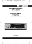
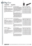
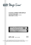
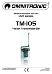
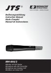
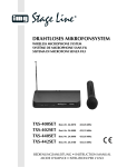
SENDER FÜR 16-KANAL-AUDIOÜBERTRAGUNGSSYSTEM
TRANSMITTER FOR 16-CHANNEL AUDIO TRANSMISSION SYSTEM
ÉMETTEUR POUR SYSTÈME DE TRANSMISSION AUDIO 16 CANAUX
TRASMETTITORE PER SISTEMA DI TRASMISSIONE AUDIO A 16 CANALI
863 – 865 MHz
ATS-10TL
ATS-10TM
Best.-Nr. 24.3520
Best.-Nr. 24.3510
BEDIENUNGSANLEITUNG • INSTRUCTION MANUAL
MODE D’EMPLOI • ISTRUZIONI PER L’USO • GEBRUIKSAANWIJZING
MANUAL DE INSTRUCCIONES • INSTRUKCJA OBSŁUGI
D
A
CH
Bevor Sie einschalten ...
F
B
CH
Avant toute utilisation ...
GB Before you switch on ...
Wir wünschen Ihnen viel Spaß mit
Ihrem neuen Gerät von „img Stage
Line“. Bitte lesen Sie diese Bedienungsanleitung vor dem Gebrauch
gründlich durch und heben Sie sie
für ein späteres Nachlesen auf.
Der deutsche Text beginnt auf Seite 4.
We wish you much pleasure with your
new “img Stage Line” unit. Please
read these operating instructions
carefully prior to operating the unit
and keep them for later use.
The English text starts on page 7.
I
Nous vous souhaitons beaucoup de
plaisir à utiliser cet appareil “img
Stage Line”. Veuillez lire entièrement
cette notice d’utilisation avant la mise
en service et conservez-la pour une
consultation ultérieure.
La version française commence à la
page 10.
NL Alvorens u inschakelt ...
B Wij wensen u veel plezier met uw
nieuw toestel van “img Stage Line”.
Lees deze bedieningshandleiding
grondig door, alvorens het toestel in
gebruik te nemen, en bewaar ze voor
latere raadpleging.
De Nederlandse tekst begint op pagina 16.
Prima di accendere ...
Vi auguriamo buon divertimento con il
Vostro nuovo apparecchio “img Stage
Line”. Vi preghiamo di leggere attentamente le presenti istruzioni prima
della messa in funzione e di conservarle per un uso futuro.
Il testo italiano comincia a pagina 13.
E
Antes de la utilización … ...
Le deseamos una buena utilización
para su nuevo aparato “img Stage
Line”. Por favor, lea este manual de
instrucciones detalladamente antes
de hacer funcionar la unidad y guárdelo para una utilización posterior.
El texto en español empieza en la
página 19.
PL Przed Uruchomieniem ...
Życzymy zadowolenia z nowego
produktu “img Stage Line”. Prosimy
o uważne przeczytanie poniższej
instrukcji przed użyciem urządzenia.
Tekst polski zaczyna się na stronie 22.
®
2
w w w.imgstageline.com
ATS-10TM
ATS-10TL
1
1
2
2
4
ATS-10TM
ATS-10TL
➀
3
3
MIC.
ANT.
ON
OFF
LINE
BATT.
ANT.
ON
LOW
STAND BY
OFF
BATT.
LOW
STAND BY
➁
5 6
8
6
C
4
2
E
0
10
OPEN
8
9
7
CHANNEL
SELECT
7
A
5 6
11
➂
3
8
D
A
Bitte klappen Sie die Seite 3 heraus. Sie
sehen dann immer die beschriebenen Bedienelemente und Anschlüsse.
CH
1 Übersicht der Bedienelemente und
Anschlüsse
1 Antenne
2 Lautstärkeregler
3 Kontakte zum Aufladen der eingesetzten
Akkus über die als Zubehör erhältliche
Ladestation ATS-10PS
4 nur bei Modell ATS-10TM:
eingebautes Mikrofon
5 Gewindebuchse zum Aufschrauben der
Antenne [siehe Position (1), Abb. 1]
6 3,5-mm-Mono-Klinkenbuchse
– bei Modell ATS-10TM:
zum Anschluss des mitgelieferten Krawattenmikrofons
– bei Modell ATS-10TL:
zum Anschluss eines Audiogerätes mit
Line-Ausgangspegel (z. B. Kassettenrecorder, MD-Recorder)
7 Schiebeschalter zum Ein-/Ausschalten
Schalter links (ON)
Gerät eingeschaltet und betriebsbereit
Schalter in der Mitte (STAND BY)
Gerät im Stand-by-Modus, d. h. es ist
eingeschaltet, überträgt aber kein Audiosignal
Schalter rechts (OFF)
Gerät ausgeschaltet
8 LED-Statusanzeige
a im Normalbetrieb:
Nach dem Einschalten blitzt die LED
kurz rot auf und leuchtet danach permanent grün. Nach dem Ausschalten
wechselt sie kurzzeitig auf Rot und
erlischt danach ganz.
b bei geringer Akku-/Batterieladung:
Leuchtet die LED permanent rot, sind
die Akkus bzw. Batterien fast erschöpft.
4
9 Drehschalter zur Auswahl des Übertragungskanals (16 Schalterstellungen)
10 Gürtelklemme
11 Batteriefachdeckel
2 Wichtige Hinweise für den
Gebrauch
Das Gerät entspricht allen erforderlichen
Richtlinien der EU und ist deshalb mit
gekennzeichnet.
● Das Gerät ist nur zur Verwendung im
Innenbereich geeignet. Schützen Sie es
vor Feuchtigkeit und Hitze (zulässiger Einsatztemperaturbereich 0 – 40 °C).
● Verwenden Sie für die Reinigung nur ein
trockenes, weiches Tuch, niemals Chemikalien oder Wasser.
● Setzen Sie immer zwei Akkus bzw. Batterien des gleichen Typs ein.
● Nehmen Sie bei längerem Nichtgebrauch
(z. B. länger als eine Woche) die Akkus/
Batterien heraus. So bleibt das Gerät bei
einem eventuellen Auslaufen der Akkus/
Batterien unbeschädigt.
● Wird das Gerät zweckentfremdet, falsch
bedient oder nicht fachgerecht repariert,
kann keine Haftung für daraus resultierende Sach- oder Personenschäden und keine Garantie für das Gerät übernommen
werden.
Soll das Gerät endgültig aus dem Betrieb
genommen werden, übergeben Sie es zur
umweltgerechten Entsorgung einem örtlichen Recyclingbetrieb.
Werfen Sie verbrauchte Batterien/defekte Akkus
nicht in den Hausmüll, sondern geben Sie sie nur in
den Sondermüll (z. B. Sammelbehälter bei Ihrem Einzelhändler).
3 Einsatzmöglichkeiten
Dieser Sender bildet in Verbindung mit einem
oder mehreren Empfänger/n ATS-10R ein
mobiles Funk-Übertragungssystem für Sprache und Musik, das sich z. B. für Gruppenführungen, mehrsprachige Vorträge, audiogestütztes Lernen etc. einsetzen lässt. Für die
Funkübertragung stehen 16 Kanäle im Frequenzbereich 863 – 865 MHz zur Verfügung.
(Zur Nutzung mehrerer Kanäle gleichzeitig
siehe Hinweis in Kap. 5.)
Der Sender wird in zwei Ausführungen geliefert:
Modell ATS-10TM für den Mikrofonbetrieb:
mit eingebautem Mikrofon und beiliegendem Elektret-Krawattenmikrofon
Modell ATS-10TL für den Betrieb mit einem
Audiogerät: mit Anschluss für ein Gerät
mit Line-Ausgangspegel (z. B. Kassettenrecorder)
3.1 Konformität und Zulassung
Hiermit erklärt MONACOR INTERNATIONAL,
dass sich die Sender ATS-10TL und ATS10TM in Übereinstimmung mit den grundlegenden Anforderungen und den übrigen
einschlägigen Bestimmungen der Richtlinie
1995/5/EG befinden. Die Konformitätserklärungen können im Internet über die Homepage von MONACOR INTERNATIONAL
(www.imgstageline.com) abgerufen werden.
Die Sender sind für den Betrieb in den
EU- und EFTA-Staaten allgemein zugelassen und anmelde- und gebührenfrei.
4 Stromversorgung
Der Sender wird über die zwei mitgelieferten
NiMH-Akkus gespeist. Als Zubehör ist aus
dem Programm von „img Stage Line“ die Ladestation ATS-10PS zum bequemen und
schnellen Aufladen der Akkus erhältlich.
Anstelle der Akkus können auch zwei
nicht wiederaufladbare 1,5-V-Batterien der
Größe Mignon (AA) verwendet werden.
1) Die geriffelte Fläche auf dem Batteriefachdeckel (11) leicht eindrücken und den
Deckel gleichzeitig nach unten abziehen.
2) Die Akkus bzw. Batterien, mit den Plusund Minusanschlüssen wie im Fach aufgedruckt, einsetzen.
3) Den Batteriefachdeckel wieder aufsetzen
und einrasten.
D
A
CH
5 Inbetriebnahme
1) Die beiliegende Antenne (1) in die Gewindebuchse ANT. (5) schrauben.
2) Für den Sender ATS-10TM kann das eingebaute Mikrofon (4) oder das beiliegende Krawattenmikrofon genutzt werden.
Bei Verwendung des Krawattenmikrofons
dieses an die Buchse MIC. (6) anschließen (das eingebaute Mikrofon ist damit
abgeschaltet). Den mitgelieferten Windschutz auf das Krawattenmikrofon setzen.
Das Mikrofon über seinen Halter an der
Kleidung (z. B. Krawatte, Revers) festklemmen.
An den Sender ATS-10TL den Ausgang
eines Audiogeräts mit Line-Ausgangspegel
(z. B. Kassetten- oder MD-Recorder, CDSpieler) über einen 3,5-mm-Klinkenstecker
an die Buchse LINE (6) anschließen.
3) Mit dem Kanalwahlschalter CHANNEL
SELECT (9) aus den 16 Übertragungskanälen den Kanal auswählen, auf dem
gesendet werden soll: Den Schalter mit einem schmalen Gegenstand, z. B. Schraubendreher, auf eine der 16 Schalterpositionen drehen.
2
4
6
0
8
E
C
A
Beispiel:
Bei dieser Schalterposition ist
Kanal 1 angewählt.
Den bzw die Empfänger auf den gleichen
Kanal einstellen.
4) Den Sender mit der Klemme (10) an der
Kleidung befestigen, z. B. am Gürtel.
5
D
A
CH
5) Zum Einschalten des Senders den Schiebeschalter (7) nach links auf ON stellen.
(In der Mittelstellung STAND BY ist der
Sender zwar auch eingeschaltet, aber
stumm d. h. es wird kein Ton übertragen.)
Nach dem Einschalten blitzt die LED
BATT. LOW (8) kurz rot auf und leuchtet
dann permanent grün. Leuchtet sie jedoch permanent rot, sind die Akkus/Batterien fast erschöpft und müssen aufgeladen bzw. ersetzt werden.
6) Den bzw. die Empfänger einschalten.
7) Mit dem Regler VOL (2) die gewünschte
Lautstärke für das gesendete Audiosignal
einstellen. Am Empfänger bzw. an den
Empfängern mit dem Lautstärkeregler die
gewünschte Wiedergabelautstärke einstellen.
8) Bei schlechtem oder gestörtem Empfang
überprüfen, ob
a auf einem anderen Übertragungskanal
der Empfang besser ist.
b die Akkus bzw. Batterien der Geräte
verbraucht sind (LED am Gerät leuchtet permanent rot).
c den Abstand zwischen Sender und
Empfänger zu groß ist.
d der Empfang durch Gegenstände in
der Übertragungsstrecke gestört ist.
e sich der Empfang durch Schwenken
der Senderantenne verbessern lässt.
9) Zum Ausschalten des Senders den Schiebeschalter (7) nach rechts auf OFF stellen: Die LED BATT. LOW (8) wechselt
nach dem Ausschalten von Grün auf Rot
und erlischt dann ganz.
Hinweis für den Mehrkanal-Betrieb
(Betrieb mehrerer ATS-10-Systeme gleichzeitig)
Wenn mehrere, auf unterschiedlichen Kanälen sendende ATS-10-Systeme gleichzeitig
eingesetzt werden, kann es aufgrund der
geringen Frequenzabstände im Übertragungsbereich 863 – 865 MHz zu Störeinstrahlungen zwischen den Kanälen kommen. Um
Störungen auszuschließen, ist es daher empfehlenswert, nicht mehr als zwei Übertragungssysteme gleichzeitig zu betreiben. Bei
gleichzeitiger Verwendung mehrerer Systeme sollte der Abstand zwischen den einzelnen Systemen möglichst hoch sein.
6 Technische Daten
Gerätetyp: . . . . . . . . . 16-Kanal-PLLSender für drahtlose
Audio-Übertragung
Funkfrequenzbereich: 863 – 865 MHz
Sendeleistung: . . . . . ≤ 10 mW
Reichweite: . . . . . . . . min. 50 m
Einsatztemperatur: . . 0 – 40 °C
Stromversorgung: . . . über die zwei mitgelieferten 1,2-V-NiMHAkkus oder über
zwei 1,5-V-Batterien,
Größe Mignon (AA)
Abmessungen: . . . . . 92 x 65 x 25 mm
Gewicht: . . . . . . . . . . 78 g (ohne Akkus)
Änderungen vorbehalten.
Diese Bedienungsanleitung ist urheberrechtlich für MONACOR ® INTERNATIONAL GmbH & Co. KG
geschützt. Eine Reproduktion für eigene kommerzielle Zwecke – auch auszugsweise – ist untersagt.
6
Please unfold page 3. Then you can always
see the operating elements and connections described.
1 Operating Elements and
Connections
1 Antenna
2 Volume control
3 Contacts for charging the inserted rechargeable batteries via the charging station ATS-10PS available as an accessory
4 Model ATS-10TM only:
integrated microphone
5 Threaded jack for screwing on the antenna [see position (1), fig. 1]
6 3.5 mm mono jack
– model ATS-10TM:
for connecting the supplied tie clip
microphone
– model ATS-10TL:
for connecting an audio unit with line
output level (e. g. cassette recorder,
MD recorder)
7 Sliding switch for switching on or off
switch at the left stop (ON)
unit switched on and ready for operation
switch in mid-position (STAND BY)
unit in stand-by mode, i. e. it is switched
on but does not transmit any audio signal
switch at the right stop (OFF)
unit switched off
8 Status LED
a normal operation:
After switching on, the LED shortly
shows red before permanently showing green. After switching off, it shortly
shows red before it is completely
extinguished.
b low batteries:
If the LED permanently shows red, the
(rechargeable) batteries are almost
exhausted.
9 Selector switch for the transmission
channel (16 positions)
10 Belt clip
11 Battery compartment cover
GB
2 Important Notes
The unit corresponds to all required directives
of the EU and is therefore marked with .
● The unit is suitable for indoor use only. Protect it against humidity and heat (admissible ambient temperature range 0 – 40 °C).
● For cleaning only use a dry, soft cloth;
never use chemicals or water.
● Always insert two (rechargeable) batteries
of the same type.
● If the unit is not used for a longer time (e. g.
for more than a week), it is recommended
to remove the (rechargeable) batteries to
prevent damage to the unit in case of battery leakage.
● No guarantee claims for the unit and no liability for any resulting personal damage or
material damage will be accepted if the unit
is used for other purposes than originally
intended, if it is not correctly operated or
not repaired in an expert way.
If the unit is to be put out of operation definitively, take it to a local recycling plant for
a disposal which is not harmful to the environment.
Never throw exhausted batteries or defective rechargeable batteries into the household rubbish:
Always take them to a special waste disposal (e. g.
collecting container at your retailer).
7
GB
3 Applications
In combination with one receiver or several
receivers of the type ATS-10R, this transmitter constitutes a mobile wireless transmission
system for speech and music which can be
used e. g. for guided tours, multilingual lectures, audio-supported learning, etc. For
wireless transmission, 16 channels in the frequency range of 863 – 865 MHz are available.
(For simultaneous use of several channels
see the note in chapter 5.)
The transmitter is available in two versions:
Model ATS-10TM for microphone operation: with integrated microphone and supplied electret tie clip microphone
Model ATS-10TL for operation with an
audio unit: with connection for a unit with
line level output (e. g. cassette recorder)
3.1 Conformity and Approval
Herewith, MONACOR INTERNATIONAL declare that the transmitters ATS-10TL and
ATS-10TM are in accordance with the basic
requirements and the other relevant regulations of the directive 1995/5/EC. The declarations of conformity can be found in the
Internet via the MONACOR INTERNATIONAL home page (www.imgstageline.com).
The transmitters are licence-free and
generally approved for operation in EU and
EFTA countries.
2) Insert the (rechargeable) batteries with
the positive and negative connections as
printed in the compartment.
3) Replace the cover and let it lock into place.
5 Operation
1) Screw the supplied antenna (1) into the
threaded jack ANT. (5).
2) For the transmitter ATS-10TM, the integrated microphone (4) or the supplied tie
clip microphone may be used. When
using the tie clip microphone, connect it to
the jack MIC. (6) [the integrated microphone is switched off in this case]. Place
the supplied windshield on the tie clip
microphone. Fasten the microphone to
your clothes (e. g. tie, lapel) via its clip.
Connect the output of an audio unit
with line output level (e. g. cassette recorder, MD recorder, CD player) via a
3.5 mm plug to the jack LINE (6) on the
transmitter ATS-10TL.
3) With the channel selector switch CHANNEL SELECT (9), select the channel
for transmission from the 16 transmission
channels: Use a narrow object, e. g.
screwdriver, to set the switch to one of the
16 positions.
2
4
6
0
4 Power Supply
The transmitter is supplied with power via the
two supplied rechargeable NiMH batteries.
For fast and convenient charging of these
batteries, the charging station ATS-10PS
from the “img Stage Line” range is available
as an accessory.
Instead of the rechargeable batteries it is
also possible to use two non-rechargeable
1.5 V batteries of size AA.
1) Slightly press the grooves on the battery
compartment cover (11) while pulling the
cover downwards at the same time.
8
8
E
C
A
Example:
In this switch position, channel 1 is selected.
Set the receiver(s) to the same channel.
4) Use the clip (10) to fasten the transmitter
to your clothes, e. g. belt.
5) To switch on the transmitter, set the sliding
switch (7) to the left stop to ON. (In the
mid-position STAND BY, the transmitter is
also switched on but it is mute, i. e. no
sound is transmitted.)
After switching on, the LED BATT.
LOW (8) shortly shows red before permanently showing green. However, if it permanently shows red, the (rechargeable)
6)
7)
8)
9)
batteries are almost exhausted and must
be recharged or replaced.
Switch on the receiver(s).
Adjust the desired volume for the audio
signal transmitted with the control VOL (2).
Adjust the desired reproduction volume on
the receiver(s) with the volume control.
In case of poor or disturbed reception,
check if
a the reception can be improved by
using a different transmission channel.
b the (rechargeable) batteries of the
units are exhausted (LED on the unit
permanently shows red).
c the distance between the transmitter
and the receiver is too long.
d the reception is disturbed by objects in
the transmission path.
e the reception can be improved by turning the antenna of the transmitter.
To switch off the transmitter, set the sliding
switch (7) to the right stop to OFF: After
switching off, the LED BATT. LOW (8)
turns from green to red before it is completely extinguished.
6 Specifications
GB
Type of unit: . . . . . . . . 16-channel PLL
transmitter for wireless audio transmission
Radio frequency range: 863 – 865 MHz
Transmitting power: . . ≤ 10 mW
Range: . . . . . . . . . . . . min. 50 m
Ambient temperature: 0 – 40 °C
Power supply: . . . . . . via the two supplied
1.2 V rechargeable
NiMH batteries or via
two 1.5 V batteries of
size AA
Dimensions: . . . . . . . 92 x 65 x 25 mm
Weight: . . . . . . . . . . . 78 g (without rechargeable batteries)
Note concerning multichannel operation
(Simultaneous operation of several ATS-10
systems)
If several ATS-10 systems transmitting on different channels are used at the same time,
interference between the channels may
result due to narrow frequency spacing in the
transmission range of 863 – 865 MHz. To prevent interference, it is therefore recommended not to operate more than two transmission
systems at the same time. In case of simultaneous operation of several systems, the
distance between the individual systems
should be as long as possible.
Subject to technical modification.
All rights reserved by MONACOR ® INTERNATIONAL GmbH & Co. KG. No part of this instruction
manual may be reproduced in any form or by any means for any commercial use.
9
F
B
CH
Ouvrez le présent livret page 3 de manière
à visualiser les éléments et branchements.
10 Clip de ceinture
11 Couvercle compartiment batterie
1 Eléments et branchements
2 Conseils importants d’utilisation
1 Antenne
2 Potentiomètre de réglage de volume
3 Contacts pour charger les accumulateurs
intégrés via la station de charge ATS10PS disponible comme accessoire
4 Uniquement sur le modèle ATS-10TM :
micro intégré
5 Prise filetée pour visser l’antenne [voir
position (1), schéma 1]
6 Prise jack 3,5 mono :
– sur le modèle ATS-10TM :
pour brancher le micro cravate livré
– sur le modèle ATS-10TL :
pour brancher un appareil audio avec
niveau sortie ligne (p. ex. magnétophone, enregistreur MD)
7 Interrupteur pour marche/arrêt
interrupteur à gauche (ON) :
appareil allumé et prêt à fonctionner
interrupteur au milieu (STAND BY)
appareil en mode stand-by, c’est-àdire qu’il est allumé mais il ne transmet
aucun signal audio
interrupteur à droite (OFF)
l’appareil est éteint
8 LED témoin d’état
a en mode normal
après la mise sous tension, la LED
brille brièvement en rouge et brille ensuite tout le temps en vert. Après l’arrêt, la LED passe brièvement en rouge
puis s’éteint.
b en cas de charge faible des accus/batteries
la LED brille en permanence en rouge
si les accumulateurs/batteries sont
presque vides
9 Sélecteur rotatif du canal de transmission
(16 positions)
10
L’appareil répond à toutes les directives nécessaires de l’Union Européenne et porte
donc le symbole .
● L’appareil n’est conçu que pour une utilisation en intérieur. Protégez-le de l’humidité
et de la chaleur (plage de température de
fonctionnement autorisée : 0 – 40 °C).
● Pour le nettoyer, utilisez uniquement un
chiffon sec et doux, en aucun cas de produits chimiques ou d’eau.
● Placez toujours deux accumulateurs ou
batteries de même type.
● En cas de non utilisation prolongée (p. ex.
supérieure à une semaine), retirez les
accumulateurs/batteries. On évite ainsi
que l’appareil ne soit endommagé si les
accumulateurs/batteries venaient à couler.
● Nous déclinons toute responsabilité en cas
de dommages corporels ou matériels résultants si l’appareil est utilisé dans un but
autre que celui pour lequel il a été conçu,
s’il n’est pas correctement utilisé ou s’il
n’est pas réparé par une personne habilitée ; de même, la garantie deviendrait
caduque.
Lorsque l’appareil est définitivement retiré
du marché, vous devez le déposer dans
une usine de recyclage de proximité pour
contribuer à son élimination non polluante.
Ne jetez pas les batteries usagées/accumulateurs
défectueux dans la poubelle domestique mais déposez-les dans un container spécifique ou reportez-les
à votre revendeur.
3 Possibilités d’utilisation
Combiné à un ou plusieurs récepteurs ATS10R, cet émetteur permet de constituer un
système de transmission audio 16 canaux
sans fil pour le discours ou la musique pouvant être utilisé dans des visites guidées,
conférences multilingues, apprentissage à
assistance audio …. Pour la transmission
sans fil, 16 canaux, dans la plage de fréquence 863 – 865 MHz sont disponibles (voir le
conseil du chapitre 5 pour utiliser simultanément plusieurs canaux).
L’émetteur est livré en deux versions :
modèle ATS-10TM pour le fonctionnement
micro : avec micro intégré et micro cravate
électret livré
modèle ATS-10TL pour le fonctionnement
avec un appareil audio : avec branchement
pour un appareil avec niveau sortie ligne
(p. ex. magnétophone)
3.1 Conformité et autorisation
Par la présente, MONACOR INTERNATIONAL déclare que les émetteurs ATS-10TL
et ATS-10TM se trouvent en conformité
avec les exigences fondamentales et les
réglementations inhérentes à la directive
1995/5/CE. Les certificats de conformité
peuvent être appelés via la page d’accueil du site internet de MONACOR INTERNATIONAL (www.imgstageline.com ou
www.monacor.com).
Les émetteurs sont autorisés dans l’Union
Européenne et les pays de l’A.E.L.E et ne
nécessitent pas de déclaration.
1) Enfoncez légèrement la surface striée du
couvercle du compartiment batterie (11)
et simultanément, poussez vers le bas le
couvercle.
L’émetteur est alimenté par deux accumulateurs NiMH livrés. Comme accessoire, la station de charge ATS-10PS de la gamme “img
Stage Line” est disponible pour une charge
rapide et confortable des accumulateurs.
A la place des accumulateurs, il est également possible d’utiliser deux batteries 1,5 V
non rechargeables de type R6.
B
CH
2) Insérez les accumulateurs ou batteries en
respectant les bornes plus et moins
comme indiqué dans le compartiment.
3) Replacez le couvercle du compartiment
batterie et enclenchez-le.
5 Fonctionnement
1) Vissez l’antenne livrée (1) dans la prise
filetée ANT. (5).
2) Pour l’émetteur ATS-10TM, on peut utiliser le micro intégré (4) ou le micro cravate
livré. Si vous utilisez le micro cravate,
reliez-le à la prise MIC (6) [le micro intégré
est alors déconnecté]. Placez la bonnette
anti-vent livrée sur le micro cravate. Fixez
le micro via sa pince sur un vêtement
(p. ex. cravate, revers de veste).
Sur l’émetteur ATS-10TL, reliez la sortie d’un appareil audio avec niveau sortie
ligne (p. ex. magnétophone, enregistreur
MD, lecteur CD) via une fiche jack 3,5 à la
prise LINE (6).
3) Avec le sélecteur de canal CHANNEL
SELECT (9), sélectionnez le canal parmi
les 16 canaux de transmission sur lequel
la transmission doit s’effectuer : tournez le
sélecteur avec un objet étroit, p. ex. tournevis, sur une des 16 positions :
2
4
6
0
4 Alimentation
F
8
E
C
A
exemple :
dans cette position, le canal 1
est sélectionné
Réglez le ou les récepteurs sur le même
canal.
4) Fixez l’émetteur avec la pince (10) sur un
vêtement, par exemple à la ceinture.
5) Pour allumer l’émetteur, mettez le sélecteur (7) à gauche sur ON (En position
médiane STAND BY, l’émetteur est égale-
11
F
B
CH
6)
7)
8)
9)
ment allumé mais il est muet, c’est-à-dire
qu’aucun son n’est transmis).
Après la mise sous tension, la LED
BATT. LOW (8) brille brièvement en rouge
puis en permanence en vert. Si la LED
brille tout le temps en rouge, les accumulateurs/batteries sont presque vides et
doivent être chargés ou remplacés.
Allumez le ou les récepteurs.
Réglez le volume souhaité pour le signal
audio émis avec le potentiomètre VOL (2).
Sur le ou les récepteurs, réglez le volume
de restitution souhaité avec le réglage de
volume.
Si la réception est mauvaise ou perturbée,
vérifiez si :
a la réception est meilleure sur un autre
canal de transmission.
b les accumulateurs ou batteries des
appareils sont usagées (la LED sur
l’appareil brille tout le temps en rouge).
c la distance entre l’émetteur et le récepteur est trop grande.
d la réception est perturbée par des
objets se trouvant dans la zone de
transmission.
e la réception peut être améliorée en
orientant l’antenne de l’émetteur.
Pour éteindre l’émetteur, mettez le sélecteur (7) sur OFF à droite : la LED BATT.
LOW (8) passe, après l’arrêt, de vert à
rouge puis s’éteint complètement.
Conseil pour un fonctionnement multicanaux
(Fonctionnement de plusieurs systèmes ATS-10
simultanément)
Si plusieurs systèmes ATS-10 sont utilisés
simultanément sur plusieurs canaux, on peut
avoir des interférences entre les canaux à
cause des faibles écarts de fréquences dans
la plage 863 – 865 MHz. Pour éviter les
inférences, il est recommandé de ne pas faire
fonctionner plus de deux systèmes de transmission à la fois. Pour une utilisation simultanée de plusieurs systèmes, la distance
entre les systèmes individuels doit être la
plus grande possible.
6 Caractéristiques techniques
Type appareil : . . . . . . émetteur PLL 16 canaux pour transmission audio sans fil
Plage de
fréquence radio : . . . . 863 – 865 MHz
Puissance émission : ≤ 10 mW
Portée : . . . . . . . . . . . 50 m min.
Température fonc. : . . 0 – 40 °C
Alimentation : . . . . . . par 2 accumulateurs
1,2 V NiMH livrés ou
par 2 batteries 1,5 V
de type R6
Dimensions : . . . . . . . 92 x 65 x 25 mm
Poids : . . . . . . . . . . . . 78 g (sans accus)
Tout droit de modification réservé.
Notice d'utilisation protégée par le copyright de MONACOR ® INTERNATIONAL GmbH & Co. KG.
Toute reproduction même partielle à des fins commerciales est interdite.
12
Vi preghiamo di aprire completamente la
pagina 3. Così vedrete sempre gli elementi
di comando e i collegamenti descritti.
1 Elementi di comando e
collegamenti
1 Antenna
2 Regolatore volume
3 Contatti per caricare le batterie ricaricabili
per mezzo della stazione di carica ATS10PS opzionale
4 solo nel modello ATS-10TM:
microfono integrato
5 Boccola filettata per avvitare l’antenna
[vedi posizione (1), fig. 1]
6 Presa jack 3,5 mm mono
– nel modello ATS-10TM:
per collegare il microfono a cravatta in
dotazione
– nel modello ATS-10TL:
per collegare un apparecchio audio
con livello d’uscita Line (p. es. registratore a cassette, registratore MD)
7 Interruttore on/off
posizione a sinistra (ON)
apparecchio acceso e pronto per l’uso
posizione centrale (STAND BY)
apparecchio in modalità stand-by, ovvero è acceso ma non trasmette nessun segnale audio
posizione a destra (OFF)
apparecchio spento
8 LED di stato
a funzionamento normale:
Dopo l’accensione, il LED si accende
brevemente di colore rosso e dopo
rimane acceso di colore verde. Dopo lo
spegnimento diventa brevemente rosso e quindi si spegne completamente.
b con carica scarsa delle batterie:
Se rimane di colore rosso, le batterie
sono quasi scariche.
9 Selettore per scegliere il canale di trasmissione (16 posizioni)
10 Clip da cintura
11 Coperchio del vano batterie
I
2 Note importanti per l’uso
L’apparecchio è conforme a tutte le direttive
richieste dell’UE e pertanto porta la sigla .
● Lo strumento è adatto solo per l’uso all’interno di locali. Proteggerlo dall’umidità e
dal calore (temperatura d’impiego ammessa fra 0 e 40 °C).
● Per la pulizia usare solo un panno morbido, asciutto; non impiegare in nessun
caso prodotti chimici o acqua.
● Inserire sempre due batterie (ricaricabili o
non) dello stesso tipo.
● Se lo strumento non viene utilizzato per un
tempo prolungato (p. es. oltre una settimana) conviene togliere le batterie per evitare
che perdano, danneggiando lo strumento.
● Nel caso d’uso improprio, d’impiego scorretto o di riparazione non a regola d’arte
dell’apparecchio, non si assume nessuna
responsabilità per eventuali danni consequenziali a persone o a cose e non si
assume nessuna garanzia per l’apparecchio.
Se si desidera eliminare l’apparecchio definitivamente, consegnarlo per lo smaltimento ad un’istituzione locale per il riciclaggio.
Non gettare le batterie scariche o difettose nelle
immondizie di casa bensì negli appositi contenitori
(p. es. presso il vostro rivenditore).
13
I
3 Possibilità d’impiego
In combinazione con uno o più ricevitori ATS10R, questo trasmettitore costituisce un sistema mobile di trasmissione senza fili per lingua parlata e per musica che può essere impiegato p. es. per la guida di gruppi, per conferenze a più lingue, per lo studio con supporto audio ecc. Per la trasmissione senza fili
sono disponibili 16 canali nelle frequenze
863 – 865 MHz. (Per sfruttare più canali contemporaneamente vedi la nota nel cap. 5.)
Il trasmettitore viene fornito in due versioni:
Modello ATS-10TM per il funzionamento con
microfono: con microfono integrato e con
microfono a elettrete a cravatta in dotazione
Modello ATS-10TL per il funzionamento con
un apparecchio audio: con collegamento
per un apparecchio con livello d’uscita
Line (p. es. registratore a cassette)
3.1 Conformità e omologazione
Con la presente, MONACOR INTERNATIONAL dichiara che i trasmettitori ATS-10TL e
ATS-10TM sono conformi ai requisiti di base e
alle relative norme della direttiva 1995/5/CE.
Le dichiarazioni di conformità possono essere
scaricate dal sito di MONACOR INTERNATIONAL (www.imgstageline.com).
I trasmettitori sono omologati per il funzionamento negli stati UE e EFTA e non richiedono registrazione e tasse.
1) Esercitare una leggera pressione sulla parte zigrinata del coperchio del vano batterie
(11) e sfilare il coperchio verso il basso.
2) Inserire le batterie rispettando i poli positivo
e negativo come stampato nel vano stesso.
3) Rimettere il coperchio e spingerlo fino allo
scatto.
5 Messa in funzione
1) Avvitare l’antenna in dotazione (1) nella
boccola filettata ANT. (5).
2) Per il trasmettitore ATS-10TM si può usare
il microfono integrato (4) oppure il microfono a cravatta in dotazione. Usando il
microfono a cravatta, collegarlo con la
presa MIC. (6) [il microfono integrato è
così disattivato]. Applicare la spugna antivento in dotazione sul microfono a cravatta
e fissare il microfono ai vestiti (p. es. alla
cravatta, al risvolto) per mezzo del clip.
Collegare l’uscita di un apparecchio
audio con livello Line (p. es. registratore
MD o a cassette, lettore CD) con la presa
LINE (6) del trasmettitore ATS-10TL per
mezzo di un jack 3,5 mm.
3) Con il selettore dei canali CHANNEL SELECT (9) scegliere il canale fra i 16 canali
disponibili che deve servire per la trasmissione: girare il selettore con un oggetto
stretto, p. es. con un cacciavite, sulla posizione desiderata.
2
4 Alimentazione
Il trasmettitore viene alimentato da due batterie
ricaricabili al NiMH in dotazione. Nel programma di “img Stage Line” è disponibile come
accessorio la stazione di carica ATS-10PS per
una ricarica rapida e comoda delle batterie.
Al posto delle batterie ricaricabili si possono usare anche due batterie normali di
1,5 V tipo stilo (AA).
14
4
6
0
8
E
C
A
Esempio:
In questa posizione è stato
scelto il canale 1.
Impostare lo stesso canale sul ricevitore/
sui ricevitori.
4) Fissare il trasmettitore ai vestiti, p. es. alla
cintura, servendosi del clip (10).
5) Per accendere il trasmettitore spostare
l’interruttore (7) a sinistra su ON. (In posi-
zione centrale STAND BY il trasmettitore
è acceso, ma rimane muto; infatti, non
trasmette nessun segnale.)
Dopo l’accensione, il LED BATT. LOW
(8) si accende brevemente di color rosso
e passa poi ad un verde permanente. Se
rimane di color rosso vuol dire che le batterie sono quasi scariche e che devono
essere ricaricate o sostituite.
6) Accendere il ricevitore/i ricevitori.
7) Con il regolatore VOL (2) impostare il
volume per il segnale audio trasmesso.
Con il regolatore del volume impostare il
volume di riproduzione sul ricevitore/sui
ricevitori.
8) Nel caso di ricezione cattiva o disturbata
controllare se
a con un altro canale di trasmissione la
ricezione migliora
b le batterie degli apparecchi sono scariche (il LED sull’apparecchio rimane
rosso)
c la distanza fra trasmettitore e ricevitore
è troppo grande
d la ricezione è disturbata da oggetti che
si trovano sulla via di trasmissione
e la ricezione migliora spostando l’antenna del trasmettitore
9) Per spegnere il trasmettitore spostare l’interruttore (7) tutto a destra su OFF: dopo
lo spegnimento, il LED BATT. LOW (8)
passa da verde a rosso e quindi si spegne
completamente.
Note per il funzionamento a più canali
I
(uso contemporaneo di diversi sistemi ATS-10)
Se si usano contemporaneamente diversi
sistemi ATS-10 che trasmettono su canali
differenti, è possibile che per via delle limitate
distanze fra le frequenze nel campo
863 – 865 MHz si creino delle interferenze fra
i canali. Per escludere tali disturbi è consigliabile usare contemporaneamente non più
di due sistemi di trasmissione. Nel caso di
uso contemporaneo di più sistemi, la distanza fra i singoli sistemi dovrebbe essere la più
grande possibile.
6 Dati tecnici
Tipo di apparecchio: trasmettitore PLL a 16
canali per trasmissione
audio senza fili
Banda di frequenze
radio: . . . . . . . . . . . 863 – 865 MHz
Potenza: . . . . . . . . ≤ 10 mW
Portata: . . . . . . . . . min. 50 m
Temperatura
d’impiego: . . . . . . . 0 – 40 °C
Alimentazione: . . . . tramite le due batterie
ricaricabili di 1,2 V al
NiMH in dotazione oppure tramite due batterie 1,5 V, tipo stilo (AA)
Dimensioni: . . . . . . 92 x 65 x 25 mm
Peso: . . . . . . . . . . . 78 g (senza batterie)
Con riserva di modifiche tecniche.
La MONACOR ® INTERNATIONAL GmbH & Co. KG si riserva ogni diritto di elaborazione in qualsiasi forma
delle presenti istruzioni per l’uso. La riproduzione – anche parziale – per propri scopi commerciali è vietata.
15
NL
B
Vouw bladzijde 3 helemaal open, zodat u
steeds een overzicht hebt van de bedieningselementen en de aansluitingen.
1 Overzicht van de bedieningselementen en aansluitingen
1 Antenne
2 Volumeregelaar
3 Contacten om de aangebrachte accu’s op
te laden via het als toebehoren verkrijgbare laadstation ATS-10PS
4 Alleen bij model ATS-10TM:
geïntegreerde microfoon
5 Schroefdraadmof om de antenne vast te
schroeven [zie positie (1), fig. 1]
6 3,5 mm-monojack
– bij model ATS-10TM:
voor aansluiting van de bijgeleverde
dasspeldmicrofoon
– bij model ATS-10TL:
voor aansluiting van audioapparatuur
met lijnuitgangsniveau (b. v. cassetterecorder, minidisk-recorder)
7 Schuifschakelaar om in/uit te schakelen
Schakelaar in de linker stand (ON)
Apparaat ingeschakeld en bedrijfsklaar
Schakelaar in de middelste stand
(STAND BY)
Het apparaat bevindt zich in stand bymodus, d.w.z. het is ingeschakeld,
maar er wordt geen audiosignaal uitgezonden
Schakelaar in de linker stand (OFF)
Het apparaat is uitgeschakeld
8 LED-statusweergave
a normale werking: Na het inschakelen
knippert de LED kort in het rood en
licht ze daarna continu groen op. Na
het uitschakelen licht de LED kort rood
op en gaat ze vervolgens volledig uit.
b wanneer de accu’s/batterijen bijna leeg
zijn: Wanneer de LED continu rood oplicht, dan zijn de accu’s resp. batterijen
bijna leeg.
16
9 Draaischakelaar voor selectie van het
transmissiekanaal (16 schakelaarinstellingen)
10 Riemclip
11 Deksel van het batterijvakje
2 Belangrijke gebruiksvoorschriften
Het apparaat is in overeenstemming met alle
vereiste EU-Richtlijnen en is daarom gekenmerkt met .
● Het apparaat is enkel geschikt voor gebruik binnenshuis. Vermijd uitzonderlijk
warme plaatsen en plaatsen met een hoge
vochtigheid (toegestaan omgevingstemperatuurbereik: 0 – 40 °C).
● Verwijder het stof met een droge, zachte
doek. Gebruik zeker geen chemicaliën of
water.
● Plaats uitsluitend twee accu’s resp. batterijen van hetzelfde type in het apparaat.
● Indien u het toestel voor een langere periode (b.v. langer dan een week) niet gebruikt, dient u de batterijen eruit te nemen.
Zo blijft het apparaat onbeschadigd bij
eventueel uitlopen van de accu’s/batterijen.
● In geval van ongeoorloofd of verkeerd
gebruik, verkeerde aansluiting, foutieve
bediening of van herstelling door een nietgekwalificeerd persoon vervalt de garantie
en de verantwoordelijkheid voor hieruit
resulterende materiële of lichamelijke
schade.
Wanneer het apparaat definitief uit bedrijf
wordt genomen, bezorg het dan voor verwerking aan een plaatselijk recyclagebedrijf.
Geef lege of defecte batterijen resp. accu’s niet met
het gewone huisvuil mee, maar verwijder ze als KGA
(bijvoorbeeld de inzamelbox in de gespecialiseerde
elektrozaak).
3 Toepassingen
Deze zender vormt in combinatie met een of
meerdere ontvangers ATS-10R een mobiel
radiotransmissiesysteem voor spraak en muziek, dat bijvoorbeeld voor groepsrondleidingen of voordrachten in verschillende talen
kan worden gebruikt. Voor de radiotransmissie staan er 16 kanalen in het frequentiebereik 863 – 865 MHz ter beschikking. (Voor het
gebruik van meerdere kanalen tegelijk raadpleegt u de aanwijzingen in hoofdstuk 5.)
De zender wordt in twee uitvoeringen geleverd:
Model ATS-10TM voor microfoongebruik:
met geïntegreerde microfoon en bijgeleverde electret-dasspeldmicrofoon
Model ATS-10TL voor gebruik met een audiotoestel: met aansluiting voor apparatuur
met lijnuitgangsniveau (b.v. cassetterecorder)
3.1 Conformiteit en goedkeuring
Hiermee verklaart MONACOR INTERNATIONAL dat de zenders ATS-10TL en ATS-10TM
in overeenstemming zijn met de basisvereisten en de overige geldende bepalingen van
de richtlijn 1995 / 5 / EG. De conformiteitsverklaringen kunnen op het internet via de
website van MONACOR INTERNATIONAL
(www.imgstageline.com) worden gedownload.
Het gebruik van de zenders is algemeen
toegelaten in de Lidstaten van de EU en
de EFTA, en is vrij van registratie en van
taksen.
4 Voedingsspanning
De zender wordt via de twee meegeleverde
NiMH-accu’s gevoed. Als toebehoren is uit
het gamma van “img Stage Line” het laadstation ATS-10PS verkrijgbaar om accu’s eenvoudig en snel op te laden.
In de plaats van de accu’s kunt u ook twee
niet oplaadbare mignon-batterijen van 1,5 V
(AA) gebruiken.
1) Druk voorzichtig op het geribbelde oppervlak van de batterijvakje (11) en schuif het
deksel tegelijk naar beneden.
2) Breng de accu’s resp. batterijen aan met
de positieve en negatieve aansluitingen
zoals in het vakje voorgedrukt.
3) Plaats het deksel van het batterijvak terug
en laat het vastklikken.
NL
B
5 Ingebruikneming
1) Schroef de bijgeleverde antenne (1) vast
in de schroefdraadmof ANT. (5).
2) Voor de zender ATS-10TM kan de geïntegreerde microfoon (4) of de bijgeleverde
dasspeldmicrofoon worden gebruikt. Indien u de dasspeldmicrofoon gebruikt,
sluit u deze aan op de jack MIC. (6) [de geïntegreerde microfoon is daarmee uitgeschakeld]. Plaats het bijgeleverde windscherm op de dasspeldmicrofoon. Klem
de microfoon met de clip op uw kleding
(b.v. das, revers).
Sluit op de zender ATS-10TL de uitgang
van audioapparatuur met lijnuitgangsniveau (b. v. cassetterecorder of minidisk-recorder, cd-speler) via een 3,5 mm-stekker
aan op de jack LINE (6).
3) Selecteer met de kanaalkeuzeschakelaar
CHANNEL SELECT (9) uit de 16 transmissiekanalen een kanaal waarop moet worden verzonden: Draai de schakelaar met
een smal voorwerp, b.v. een schroevendraaier, in een van de 16 schakelaarstanden.
2
4
6
0
8
E
C
A
Voorbeeld:
Bij deze schakelaarstand is
het kanaal 1 geselecteerd.
Stel de ontvanger(s) in op hetzelfde kanaal.
4) Bevestig de zender met de clip (10) op
een kledingsstuk, b.v. de riem.
5) Om de zender in te schakelen, plaatst u
de schuifschakelaar (7) naar links in de
stand ON. (In de middelste stand STAND
17
NL
B
6)
7)
8)
9)
BY is de zender weliswaar ook ingeschakeld, maar gedempt; d.w.z. er wordt geen
geluid overgedragen.)
Na het inschakelen knippert de LED
BATT. LOW (8) kort in het rood en licht ze
daarna continu groen op. Wanneer de
LED echter continu rood oplicht, zijn de
accu’s/batterijen bijna leeg en moeten ze
worden geladen resp. vervangen.
Schakel de ontvanger(s) in.
Stel met de regelaar VOL (2) het gewenste volume in voor het verzonden audiosignaal. Stel op de ontvanger(s) met de
volumeregelaar het gewenste weergavevolume in.
Bij slechte of gestoorde ontvangst, controleert u of
a de ontvangst op een ander transmissiekanaal beter is.
b de accu’s resp. batterijen van de apparaten leeg zijn (LED op het apparaat
licht continu rood op).
c de afstand tussen de zender en ontvanger te groot is.
d de ontvangst door voorwerpen in de
transmissielijn verstoord is.
e de ontvangst door draaien van de zenderantenne kan worden verbeterd.
Om de zender uit te schakelen, plaatst u
de schuifschakelaar (7) naar rechts in de
stand OFF: De LED BATT. LOW (8) wisselt na het uitschakelen van groen naar
rood en gaat vervolgens volledig uit.
Aanwijzing voor het gebruik van meerdere
kanalen
(Gebruik van meerdere ATS-10-systemen tegelijk)
Wanneer u tegelijk meerdere ATS-10-systemen gebruikt, die op verschillende kanalen
uitzenden, kunnen er door de geringe frequentieafstanden in het transmissiebereik
863 – 865 MHz interfererende stralingen ontstaan tussen de kanalen. Om storingen uit te
sluiten, is het daarom aanbevolen niet meer
dan twee transmissiesystemen tegelijk te
gebruiken. Indien u meerdere systemen tegelijk gebruikt, moet de afstand tussen de
afzonderlijke systemen zo groot mogelijk zijn.
6 Technische gegevens
Apparaattype: . . . . . . . 16-kanaals PLL-zender voor draadloze
audiotransmissie
Radiofrequentiebereik: 863 – 865 MHz
Zendvermogen: . . . . . ≤ 10 mW
Reikwijdte: . . . . . . . . . min. 50 m
Omgevingstemperatuurbereik: . . . 0 – 40 °C
Voedingsspanning: . . via de twee bijgeleverde NiMH-accu’s
van 1,2 V of via twee
mignon-batterijen
van 1,5 V (AA)
Afmetingen: . . . . . . . . 92 x 65 x 25 mm
Gewicht: . . . . . . . . . . 78 g (zonder accu’s)
Wijzigingen voorbehouden.
Deze gebruiksaanwijzing is auteursrechterlijk beschermd voor MONACOR ® INTERNATIONAL GmbH &
Co. KG. Reproductie voor eigen commerciële doeleinden, ook bij wijze van uitzondering, is niet toegestaan.
18
Abrir el presente libro página 3 de manera
a visualizar los elementos y las conexiones.
9 Selector rotativo del canal de transmisión
(16 posiciones)
E
10 Clip de cintura
11 Tapa compartimiento baterias
1 Elementos y conexiones
1 Antena
2 Potenciómetro de volumen
3 Contactos para cargar las baterias recargables insertadas mediante la estación
de carga ATS-10PS disponible como accesorio.
4 El modelo ATS-10TM dispone de un micro integrado
5 Toma enroscada para la antena [vea posición (1), esquema 1]
6 Toma jack 3,5 mono:
– en el modelo ATS-10TM:
para conectar el micro de solapa entregado.
– en el modelo ATS-10TL:
para conectar un aparato audio con
nivel salida línea [por ejemplo grabador (cassette), grabador MD]
7 Interruptor ON/OFF
Interruptor en la posición izquierda (ON):
aparato conectado y listo para funcionar
Interruptor en el medio (STAND BY)
aparato en modo stand-by, es decir
que esté conectado pero no transmite
ninguna señal audio
Interruptor en la posición derecha (OFF)
el aparato está desconectado.
8 LED testigo de funcionamiento
a en modo normal:
Después de la puesta en marcha, el
LED brilla brevemente de color rojo y
después brilla en permanencia de color verde. Al apagar el aparato, el LED
pasa brevemente de color rojo y se
apaga completamente.
b en caso de que las baterias estén bajas en carga:
Si el LED brilla en permanencia de color rojo, las baterias están casi vacías.
2 Notas importantes para el uso
El aparato corresponde a todas las Directivas
requeridas de la UE y por ello está marcado
con .
●
El aparato está fabricado únicamente para
una utlizacion en interior. No lo exponga a
la humedad y al calor (temperatura de funcionamiento autorizada: 0 – 40 °C).
●
Para limpiar el aparato utilice únicamente
un paño suave y seco, no utilice nunca
agua o productos químicos.
●
Coloque siempre dos baterias de mismo
tipo.
●
En el caso de no utilizar el aparato durante
un tiempo prolongado (por ejemplo superior a una semana), saque las baterías.
Evitará así que el aparato sufra daños si
las baterias se derretirán.
●
Rechazamos toda responsabilidad en caso de daños corporales o materiales resultantes de una utilización del aparato inadecuada a sus capacidades y características,
si no se utiliza correctamente, o repara por
un técnico habilitado y cualificado; además
por todos estos mismos motivos el aparato
carecería de todo tipo de garantía.
Cuando el aparato está definitivamente sacado del servicio, deposítelo en una fábrica
de reciclaje para contribuir a una eliminación no contaminante.
No tire nunca las baterías usadas o defectuosas en
una basura doméstica, tírelas en un container adaptado o devuélvalas a su detallista.
19
E
3 Posibilidades de utilización
Combinado a uno o varios receptores ATS10R, este emisor permite constituir un sistema
de transmisión audio inalámbrico para discursos y programas musicales que se pueden
utilizar durante visitas de grupos, conferencias
de varios idiomas, aprendizaje en asistencia
audio … Para la transmisión inalámbrica, 16
canales, frecuencias emisión 863 – 865 MHz,
están disponibles (vea consejo del capítulo 5
para utilizar simultáneamente varios canales).
El emisor está entregado en dos versiones
distintas:
Modelo ATS-10TM para el funcionamiento
micro, con micro integrado y micro de
solapa electret entregado.
Modelo ATS-10TL para el funcionamiento
con un aparato audio: con conexión para
un aparato con nivel salida línea (por
ejemplo cassette).
3.1 Conformidad y aprobación
Por la presente, MONACOR INTERNATIONAL declara que los emisores ATS-10TL y
ATS-10TM son acordes a los requisitos básicos y a las demás regulaciones pertinentes
de la Directiva 1995/5/EC. Las declaraciones
de conformidad se pueden encontrar en Internet mediante la página web de MONACOR
INTERNATIONAL (www.imgstageline.com).
Los emisores están libres de licencia y
están aprobados de manera general para el
funcionamiento en la UE y en los países de la
AELC.
1) Pulse ligeramente la superficie estriada de
la tapa del compartimiento batería (11) y simultáneamente, pulse hacia abajo la tapa.
2) Inserte las baterias respetando los bornes
positivos y negativos como indicado dentro del compartimiento.
3) Coloque y encaje la tapa del compartimiento batería.
5 Funcionamiento
1) Atornille la antena entregada (1) en la
toma enroscada ANT. (5).
2) Para el emisor ATS-10TM, puede utilizar
el micro integrado (4) o el micro de solapa
entregado. Si utiliza el micro de solapa,
conéctelo a la toma MIC (6) [el micro integrado se desconecta automáticamente].
Coloque la espuma anti viento entregado
sobre el micro de solapa. Fije el micro
mediante su pinza sobre una prenda (por
ejemplo corbata, chaqueta).
En el emisor ATS-10TL, conecte la salida de un aparato audio con nivel salida
línea [por ejemplo grabador (cassette),
grabador MD, lector CD] vía una toma
jack 3,5 a la toma LINE (6).
3) Con el selector de canal CHANNEL SELECT (9), seleccione el canal entre los 16
canales de transmisión en el cual la transmisión se debe de efectuar: gire el selector
con un pequeño objeto tal como un atornillador, sobre una de las 16 posiciones:
2
4 Alimentación
El emisor está alimentado por dos baterias
recargables NiMH entregadas. Como accesorio, tiene a disponibilidad la estación de
carga ATS-10PS de la gama “img Stage Line”
para una carga rápida y conveniente de las
baterias.
También es posible utilizar dos baterias
de 1,5 V no recargable de tipo R6 en lugar de
las baterías recargables.
20
4
6
0
8
E
C
A
Ejemplo:
en esta posición se selecciona el canal 1.
Regule el o los receptores en el mismo
canal.
4) Fije el emisor con la pinza (10) sobre una
prenda, por ejemplo en el cinturón.
5) Para conectar el emisor, ponga el selector
(7) hacia la izquierda en la posición ON
(En posición mediana STAND BY, el emi-
sor también está conectado pero mudo,
es decir, que no transmite ningún sonido).
Después de la puesta en marcha, el
LED BATT. LOW (8) brilla brevemente en
rojo y después en permanencia en verde.
Si el LED brilla siempre en rojo, las baterias están casi vacías y deben cargarse o
cambiarse.
6) Conecte el o los receptores.
7) Regule el volumen para la señal audio
emitida con el potenciómetro VOL (2). En
el o los receptores, regule el volumen de
restitución con el potenciómetro de volumen.
8) Si la recepción es mala o perturbada, verifique si:
a la recepción es mejor en otro canal de
transmisión.
b las baterias de los aparatos están usadas (el LED del aparato brilla en permanencia de color rojo).
c la distancia entre el emisor y el receptor es demasiado grande.
d la recepción está perturbada por objetos que se encuentran en la zona de
transmisión.
e la recepción puede mejorar orientando
la antena de recepción.
9) Para apagar el emisor, ponga el sector (7)
en la posición OFF a la derecha: el LED
BATT. LOW (8) pasa, después del paro,
del color verde al color rojo y se apaga
completamente.
Consejos para un funcionamiento con
varios canales
E
(Funcionamiento de varios sistemas ATS-10
simultáneamente)
Si utiliza varios sistemas ATS-10 simultáneamente en varios canales, puede producir interferencias entre los canales a causa
de las bajas diferencias de frecuencias
863 – 865 MHz. Para evitar interferencias, le
aconsejamos de no hacer funcionar más de
dos sistemas de transmisión a la vez. Para
una utilización simultanea de varias sistemas, la distancia entre cada sistema debería
de ser la más grande posible.
6 Características técnicas
Tipo aparato: . . . . . . . emisor PLL
16 canales para la
transmisión audio
inalámbrica
Frecuencias emisión: 863 – 865 MHz
Potencia emisió: . . . . ≤ 10 mW
Alcance: . . . . . . . . . . 50 m min.
Temperatura func.: . . 0 – 40 °C
Alimentación: . . . . . . . con 2 baterias recargables de 1,2 V
NiMH entregadas o
con 2 baterias 1,5 V
de tipo R6
Dimensiones: . . . . . . 92 x 65 x 25 mm
Peso: . . . . . . . . . . . . . 78 g (sin baterias)
Sujeto a modificaciones técnicas.
Manual de instrucciones protegido por el copyright de MONACOR ® INTERNATIONAL GmbH & Co. KG.
Toda reproducción mismo parcial para fines comerciales está prohibida.
21
PL
Proszę otworzyć instrukcję na stronie 3,
aby móc widzieć opisywane elementy
sterujące i połączenia.
1 Elementy Sterujące i Gniazda
Połączeniowe
1 Antena
2 Regulator głośności
3 Styki do ładowania baterii za pomocą
stacji ładującej ATS-10PS (z oferty img
Stage Line)
4 Tylko model ATS-10TM:
zintegrowany mikrofon
5 Gniazdo mocowania anteny [patrz pozycja (1), rys. 1]
6 Gniazdo jack mono 3,5 mm
– model ATS-10TM:
do podłączania załączonego mikrofonu krawatowego
– model ATS-10TL:
do podłączania urządzenia audio wyposażonego w wyjście liniowe (np.:
magnetofonu, nagrywarki MD)
7 Włącznik
przesunięty w lewo (ON)
urządzenie włączone i gotowe do pracy
w pozycji środkowej (STAND BY)
tryb oczekiwania – urządzenie jest
włączone, ale nie następuje transmisja
przesunięty w prawo (OFF)
urządzenie wyłączone
8 Dioda statusu
a tryb normalny:
Po włączeniu urządzenia dioda początkowo świeci się w kolorze czerwonym
zanim zaświeci się ciągle w kolorze
zielonym. Po wyłączeniu urządzenia
zaświeci się chwilowo w kolorze czerwonym do momentu całkowitego rozładowania.
b baterie rozładowane:
Jeżeli doda ciągle świeci się w kolorze czerwonym, oznacza to, że baterie
są prawie całkowicie rozładowane.
22
9 Przełącznik kanałów transmisji (16 pozycji)
11 Uchwyt na pasek
11 Pokrywa komory baterii
2 Bezpieczeństwo użytkowania
Urządzenie spełnia wymogi dyrektyw obowiązujących w Unii Europejskiej, posiada
więc oznakowanie .
● Urządzenie przeznaczone jest do użytku
tylko wewnątrz pomieszczeń. Należy
chronić je przed zalaniem i wilgocią oraz
wysoką temperaturą (dopuszczalna temperatura otoczenia pracy to 0 – 40 °C).
● Do czyszczenia urządzenia zawsze używać czystego i suchego kawałka materiału; nigdy nie należy używać wody, ani
środków chemicznych.
● Zawsze umieszczać w urządzeniu dwie baterie (akumulatorowe) tego samego typu.
● Jeżeli urządzenie nie jest używane przez
dłuższy okres czasu (np.: dłużej niż tydzień), zaleca się usunięcie z niego baterii
w celu zapobiegnięciu uszkodzeniom spowodowanym ewentualnym wyciekom
elektrolitu.
● Dostawca oraz producent nie ponoszą
odpowiedzialności za ewentualnie wynikłe szkody materialne lub uszczerbki na
zdrowiu, jeśli urządzenie było używane
niezgodnie z przeznaczeniem, zostało
niepoprawnie zainstalowane lub obsługiwane oraz było poddawane naprawom
przez nieautoryzowany personel.
Jeśli urządzenie nie będzie już nigdy więcej
używane, wskazane jest przekazanie go do
miejsca utylizacji odpadów, aby zostało zniszczone bez szkody dla środowiska.
Zużyte baterie nie powinny być wyrzucane razem ze
zwykłymi odpadkami. Należy je umieszczać w odpowiednio do tego celu przeznaczonych pojemnikach.
3 Zastosowanie
Niniejszy nadajnik w połączeniu z odbiornikiem typu ATS-10R tworzy system transmisji
audio, który może być wykorzystywany, np.:
przez przewodników wycieczek, podczas
konferencji wielojęzycznych, nauki języków
wspomaganych systemami audio, etc. Dostępnych jest szesnaście kanałów w zakresie
863 – 865 MHz. (Dla równoczesnego wykorzystania kilku kanałów patrz. rozdział 5.)
Nadajnik dostępny jest w dwóch wersjach:
Model ATS-10TM przeznaczony do pracy
transmiter mikrofonem:
wyposażony w zintegrowany mikrofon
oraz elektretowy mikrofon krawatowy
Model ATS-10TL przeznaczony do pracy z
urządzeniem audi:
możliwość połączenia z urządzeniem
audio wyposażonym w wyjście liniowe
(np.: magnetofon)
3.1 Normy i zezwolenia
Niniejszym firma MONACOR INTERNATIONAL oświadcza, że nadajniki ATS-10TL
oraz ATS-10TM spełniają wymogi dyrektywy 1995/5/EC i są zgodnie z zawartymi w niej przepisami. Deklarację zgodności można znaleźć na stronie internetowej firmy MONACOR INTERNATIONAL
(www.imgstageline.com).
Nadajniki nie wymagają zezwolenia
i zostały dopuszczone do użytkowania w
krajach należących do Unii Europejskiej oraz
Europejskiego Stowarzyszenia Wolnego
Handlu (EFTA).
1) Delikatnie wcisnąć oznaczone miejsce
na pokrywie komory baterii (11) przesuwając ją równocześnie ku dołowi.
2) Umieścić w komorze baterie zgodnie z
oznaczeniami.
3) Ponownie nałożyć osłonę baterii.
5 Obsługa
1) Dokręcić dołączoną antenę (1) do
gniazda antenowego ANT. (5).
2) W przypadku nadajnika ATS-10TM można użyć zintegrowanego mikrofonu (4),
lub dołączonego elektretowego mikrofonu krawatowego. W przypadku mikrofonu krawatowego należy podłączyć go
do gniazda MIC. (6) [w tym przypadku
mikrofon zintegrowany jest wyłączony].
Umieścić dołączony wiatrochron na mikrofonie. Przymocować mikrofon do
odzieży (np.: do krawata, klapy) za
pomocą klipsa.
W przypadku urządzenia ATS-10TL,
połączyć urządzenie źródłowe audio wyposażone w wyjście liniowe (np.: magnetofon, odtwarzacz MD, odtwarzacz CD)
za pomocą wtyku jack 3,5 mm z gniazdem LINE (6) nadajnika.
3) Za pomocą przełącznika CHANNEL SELECT (9), wybrać jeden z 16 kanałów
transmisji: Do ustawianie przełączników
należy użyć wąskiego przedmiotu (np.:
śrubokręta).
2
Nadajnik wyposażony jest w dwie baterie akumulatorowe typu NiMH. Do ładowania tych
baterii należy używać stacji ładującej ATS10PS dostępnej w ofercie “img Stage Line”.
Zamiast baterii akumulatorowych można
używać dwóch nieładowalnych baterii 1,5 V
typu AA.
4
6
0
8
E
4 Zasilanie
PL
C
A
Przykład:
W tym wypadku wybrany jest
kanał 1.
Ustawić ten sam kanał pracy odbiornika(ów).
4) Zamocować nadajnik do ubrania za
pomocą klipsa, np.: do paska.
5) Aby włączyć nadajnik należy ustawić
przełącznik (7) w pozycji ON. (W pozycji
środkowej, kiedy urządzenie ustawione
jest w trybie pracy STAND BY, jest ono
23
PL
6)
7)
8)
9)
również włączone, ale jest wyciszone –
nie następuje transmisja sygnału.)
Po włączeniu urządzenia dioda wskaźnika BATT. LOW (8) zaświeci się chwilowo w kolorze czerwonym, a następnie
będzie się świecić w kolorze zielonym.
Jeżeli świeci się ona stale w kolorze czerwonym oznacza to, że baterie są rozładowane i muszą zostać naładowane, lub
wymienione.
Włączyć odbiornik(i).
Ustawić odpowiedni poziom głośności
transmitowanego sygnału audio za pomocą regulatora VOL (2). Ustawić odpowiedni poziom głośności odbieranego
sygnału w odbiorniku(ach) za pomocą
odpowiednich regulatora(ów).
W przypadku słabego, lub zakłóconego
odbioru sygnału należy sprawdzić czy:
a odbiór może być polepszony przy
użyciu innych kanałów transmisji.
b baterie nie są rozładowane (wskaźnik
naładowania świeci się ciągle w kolorze czerwonym).
c odległość pomiędzy nadajnikiem, a
odbiornikiem jest zbyt duża.
d odbiór jest zakłócany przez obiekty
znajdujące się na ścieżce transmisji.
e jakość odbioru może być poprawiona
poprzez przestawianie anten.
Aby wyłączyć nadajnik, należy ustawić
przełącznik (7) w pozycji prawej OFF: Po
wyłączeniu wskaźnik (8) przez moment
zaświeci się kolorze czerwonym zanim
się całkowicie rozładuje.
Uwaga dotyczące pracy wielokanałowej
(Równoczesna praca kilku systemów ATS-10)
W przypadku pracy kilku systemów transmisji ATS-10 w różnych kanałach istnieje
możliwość nakładania się sygnałów pomiędzy kanałami spowodowana wąską separacją kanałów w zakresie 863 – 865 MHz. Aby
uniknąć nakładania się sygnałów nie zaleca
się korzystania z więcej niż dwóch systemów
jednocześnie. Jeżeli jednocześnie pracuje
większa liczba systemów należy usatwić
maksymalną możliwą separację kanałów.
6 Dane Techniczne
Typ urządzenia: . . . . . 16-kanałowy nadajnik transmisji bezprzewodowej audio
Zakres częstotliwości
nadawania: . . . . . . . . . 863 – 865 MHz
Moc nadajnika: . . . . . ≤ 10 mW
Zasięg: . . . . . . . . . . . . min. 50 m
Dopuszczalny zakres
temp. otoczenia pracy: 0 – 40 °C
Zasilanie: . . . . . . . . . . za pomocą dwóch
dołączonych baterii
1,2 V NiMH, lub za
pomocą dwóch
baterii 1,5 V typ AA
Rzomiary: . . . . . . . . . 92 x 65 x 25 mm
Waga: . . . . . . . . . . . . . 78 g ( bez baterii)
Może ulec zmianie.
Instrukcje obsługi są chronione prawem Copyright for MONACOR ® INTERNATIONAL GmbH & Co. KG.
Przetwarzanie całości lub części dla osobistych finansowych korzyści jest zabronione.
24
® Copyright © by MONACOR INTERNATIONAL GmbH & Co. KG, Bremen, Germany. All rights reserved. A-0208.99.03.04.2007