1
20813-03
PNOZ X2.7P / PNOZ X2.8P
4
4
4
D
Betriebsanleitung
GB Operating instructions
F
Manuel d`utilisation
Sicherheitsbestimmungen
4
4
4
E
Instrucciones de uso
I
Istruzioni per l`uso
NL Gebruiksaanwijzing
Safety Regulations
Conseils préliminaires
• Das Gerät darf nur von einer Elektrofachkraft oder unterwiesenen Personen
installiert und in Betrieb genommen
werden, die mit dieser Betriebsanleitung
und den geltenden Vorschriften über
Arbeitssicherheit und Unfallverhütung
vertraut sind. Beachten Sie die VDEsowie die örtlichen Vorschriften, insbesondere hinsichtlich Schutzmaßnahmen.
• Halten Sie beim Transport, der Lagerung
und im Betrieb die Bedingungen nach
EN 60068-2-6 ein (siehe technische
Daten). Entsorgen Sie das Gerät nach
Ablauf seiner Lebensdauer sachgerecht.
• Durch Öffnen des Gehäuses oder eigenmächtige Umbauten erlischt jegliche
Gewährleistung.
• Sorgen Sie an allen Ausgangskontakten
bei kapazitiven und induktiven Lasten für
eine ausreichende Schutzbeschaltung.
• Diese Betriebsanleitung dient der
Instruktion und ist für künftige Verwendung aufzubewahren.
• Die Sicherheitsfunktion muss mindestens
einmal im Monat ausgelöst werden.
• The unit may only be installed and
commissioned by a competent, qualified
electician or personnel instructed
accordingly, who are familiar with both
these operating instructions and the
current regulations for health and safety
at work and accident prevention. Follow
VDE and local regulations especially
regarding preventive measures
• Transport, storage and operating
conditions should all conform to EN
60068-2-6.
At the end of its lifecycle, dispose of the
unit in an environmentally safe way and
according to any relevant regulations
• Any guarantee is void if the unit is opened
or unauthorised modifications have been
carried out
• Adequate protection must be provided on
all output contacts especially with
capacitive and inductive loads.
• These operating instructions should be
retained for future reference.
• The safety function must be triggered at
least once a month.
• La mise en oeuvre de l’appareil doit être
effectuée par une personne spécialisée
en installations électriques, en tenant
compte des prescriptions des différentes
normes applicables (NF, EN, VDE...)
notamment au niveau des risques
encourus en cas de défaillance de
l’équipement électrique.
• Respecter les exigences de la norme
EN 60068-2-6 lors du transport, du
stockage et de l'utilisation de l'appareil
(voir caractéristiques techniques).
Recycler l'appareil au bout de sa durée
de vie conformement aux prescriptions.
• L’ouverture de l’appareil ou sa modification annule automatiquement la
garantie.
• Vérifiez que le pouvoir de coupure des
contacts de sortie est suffisant en cas de
circuits capacitifs ou inductifs.
• Cette notice d'installation doit être
conservée pour les applications futures.
• La fonction de sécurité doit être activée
au moins une fois par mois.
Bestimmungsgemäße Verwendung
Intended Application
Domaines d’utilisation
Das Sicherheitsschaltgerät PNOZ X2.7P/
PNOZ X2.8P ist bestimmt für den Einsatz in
• NOT-AUS-Einrichtungen
• Sicherheitsstromkreisen nach EN 602041 (VDE 0113-1), z. B. bei berührungslos
wirkenden Schutzeinrichtungen)
The PNOZ X2.7P/PNOZ X2.8P safety relay
is for use in:
• Emergency stop circuits.
• Safety Circuits according to EN 60204-1
(VDE 0113-1), e.g. with electrosensitive
protective equipment (ESPE)
Le bloc logique de sécurité PNOZ X2.7P/
PNOZ X2.8P est adapté pour :
• les circuits d’arrêt d’urgence
• les circuits de sécurité selon les normes
EN 60204-1 (VDE 0113-1) comme par ex.
les barrières immatérielles
Gerätebeschreibung
Description
Description de l’appareil
Das Sicherheitsschaltgerät PNOZ X2.7P/
PNOZ X2.8P ist in einem P-99-Gehäuse
untergebracht. Es kann mit 24 V Wechselspannung oder mit 24 V Gleichspannung
betrieben werden.
Merkmale:
• Relaisausgänge: 3 Sicherheitskontakte
(Schließer) und ein Hilfskontakt (Öffner),
zwangsgeführt
• Anschlussmöglichkeit für NOT-AUSTaster, Schutztürgrenztaster, BWS,
Starttaster
PNOZ X2.7P: überwachter Starttaster
PNOZ X2.8P: automatischer Start
möglich
• Statusanzeige
• Überwachung externer Schütze möglich
• keine galvanische Trennung
Das Schaltgerät erfüllt folgende Sicherheitsanforderungen:
• Schaltung ist redundant mit
Selbstüberwa-chung aufgebaut (EN 954-1
Kategorie 4).
• Sicherheitseinrichtung bleibt auch bei
Ausfall eines Bauteils wirksam.
• Bei jedem Ein-Aus-Zyklus der Maschine
wird automatisch überprüft, ob die Relais
der Sicherheitseinrichtung richtig öffnen
und schließen.
The Safety Relay PNOZ X2.7P/PNOZ
X2.8P is enclosed in a P-99 housing. The
unit can be operated with 24 V AC or with
24 V A DC.
Features:
• Relay outputs: 3 safety contacts (N/O)
and one auxiliary contact (N/C), positiveguided.
• Connections for emergency stop button,
safety gate limit switch, ESPE and reset
button.
PNOZ X2.7P: monitored reset button
PNOZ X2.8P: automatic reset possible
• Status indicators
• External contactor/relay monitoring
possible
• No galvanic separation
The relay complies with the following safety
requirements:
• The circuit is redundant with built-in selfmonitoring (EN 954-1 Category 4).
• The safety function remains effective in
the case of a component failure.
• The correct opening and closing of the
safety function relays is tested
automatically in each on-off cycle.
Inséré dans un boîtier P-99, le bloc logique
de sécurité PNOZ X2.7P/PNOZ X2.8P peut
être alimenté en 24 V AC ou en 24 V DC.
Particularités :
• Sorties disponibles : 3 contacts à
fermeture de sécurité et un contact à
ouverture pour signalisation
• Bornes de raccordement pour poussoirs
AU, détecteurs de position, barrières
immatérielles et poussoir de validation
PNOZ X2.7P : Auto-contrôle du poussoir
de réarmement
PNOZ X2.8P : réarmement automatique
possible
• LEDs de visualisation
• Auto-contrôle possible des contacteurs
externes
• pas d'isolation galvanique
Le relais PNOZ X2.7P/PNOZ X2.8P répond
aux exigences suivantes :
• conception redondante avec autosurveillance (selon EN 954-1 cat. 4)
• sécurité garantie même en cas de
défaillance d’un composant
• test cyclique (ouverture/fermeture des
relais internes) à chaque cycle Marche/
Arrêt de la machine
-1-
Funktionsbeschreibung
Function Description
Description du fonctionnement
Das Schaltgerät PNOZ X2.7P/PNOZ X2.8P
dient dem sicherheitsgerichteten Unterbrechen eines Sicherheitsstromkreises. Nach
Anlegen der Versorgungsspannung leuchtet
die LED "Power". Das Gerät ist betriebsbereit, wenn der Startkreis S12-S34 geschlossen wird (automatischer Start) oder
geschlossen und wieder geöffnet wird
(manueller Start).
• Eingangskreis geschlossen (z. B. NOTAUS-Taster nicht betätigt):
Relais K1 und K2 gehen in Wirkstellung
und halten sich selbst. Die Statusanzeige
"CH. 1" und "CH. 2" für Kanal 1 und 2
leuchtet. Die Sicherheitskontakte 13-14,
23-24, 33-34 sind geschlossen, der
Hilfskontakt 41-42 ist geöffnet.
• Eingangskreis wird geöffnet (z. B. NOTAUS-Taster betätigt):
Relais K1 und K2 fallen in die Ruhestellung zurück. Die Statusanzeige "CH.
1" und "CH. 2" erlischt. Die Sicherheitskontakte 13-14, 23-24, 33-34 werden
redundant geöffnet, der Hilfskontakt
41-42 geschlossen.
The PNOZ X2.7P/PNOZ X2.8P relay
provides a safety-oriented interruption of a
safety circuit. When the operating voltage is
applied the LED "Power" is illuminated. The
unit is ready for operation, when the reset
circuit S12-S34 is closed (automatic reset)
or is closed and opened again (manual
reset).
• Input circuit closed (e.g. the emergency
stop button is not pressed):
Relays K1and K2 energise and retain
themselves. The status indicators "CH. 1"
and "CH. 2" for channels 1 and 2, resp.
illuminate. The safety contacts 13-14, 2324, 33-34 are closed, the auxiliary contact
41-42 is open.
• Input circuit is opened (e.g. emergency
stop is pressed)
Relays K1 and K2 de-energise. The
status indicators "CH.1" and "CH.2" go
out. The safety contacts 13-14, 23-24,
33-34 open (redundantly) and the
auxiliary contact 41-42 closes.
Le relais PNOZ X2.7P/PNOZ X2.8P assure
de façon sure, l’ouverture d’un circuit de
sécurité. A la mise sous tension du relais
(A1-A2), la LED "Power" s'allume. Le relais
est activé si le circuit de réarmement S12S34 est fermé (réarmement automatique)
ou fermé puis réouvert (réarmement
manuel).
• Circuits d'entrée fermés (poussoir AU non
actionné) :
Les relais K1 et K2 passent en position
travail et s'auto-maintiennent. Les LEDs
"CH.1" et "CH.2" (canal 1 et canal 2)
s'allument. Les contacts de sécurité (1314, 23-24, 33-34) sont fermés et le
contact d'info. (41-42) est ouvert.
• Circuits d'entrée ouverts (poussoir AU
actionné) :
Les relais K1 et K2 retombent. Les LEDs
"CH.1" et "CH.2" s'éteingnent. Les
contacts de sécurité (13-14, 23-24, 3334) s'ouvrent et le contact d'info. (41-42)
se ferme.
UB
A1 (L+) A2 (L-)
~
S11 S12
S34
13 23 33 41
S52
+
K1
CH2
Start
Unit
S21
CH1
K2
S22
14 24 34 42
Fig. 1: Innenschaltbild/Internal Wiring Diagram/Schéma de principe
Betriebsarten
• Einkanaliger Betrieb: Eingangsbeschaltung nach VDE 0113 und EN 60204,
keine Redundanz im Eingangskreis,
Erdschlüsse im Tasterkreis werden
erkannt.
• Zweikanaliger Betrieb ohne Querschlusserkennung: Redundanter Eingangskreis,
Kurzschlüsse und Erdschlüsse im
Tasterkreis werden erkannt.
• Zweikanaliger Betrieb mit Querschlusserkennung: Redundanter Eingangskreis,
Kurzschlüsse und Erdschlüsse im
Tasterkreis und Querschlüsse zwischen
den Tasterkontakten werden erkannt.
• Nur PNOZ X2.8P: automatischer Start:
Gerät ist aktiv, sobald der Eingangskreis
geschlossen ist.
• Manueller Start: Gerät ist aktiv, wenn der
Startkreis S12-S34 geschlossen wird.
Dadurch ist ein automatischer Start des
Schaltgeräts nach Spannungsausfall und
-wiederkehr ausgeschlossen.
• Nur PNOZ X2.7P: manueller Start,
überwacht: Gerät ist nur aktiv, wenn der
Startkreis S12-S34 frühestens 110 ms
nach Schließen der NOT-AUS-Kontakte
geschlossen wird. Dadurch ist eine
automatische Aktivierung und Überbrükkung des Starttasters ausgeschlossen.
Operating Modes
• Single-channel operation: Input wiring
according to VDE 0113 and EN 60204
and no redundancy in the input circuit.
Earth faults are detected in the
emergency stop circuit.
• Two-channel operation: no short circuit
detection: Redundant input circuit. Earth
faults and short circuits in the emergency
stop circuit are detected.
• Dual-channel operation, with short circuit
detection: Redundant input circuit. Earth
faults in the emergency stop circuit and
shorts across the Emergency Stop push
button are also detected.
• Only PNOZ X2.8P: automatic reset: The
unit is active as soon as the input circuit is
closed.
• Manual reset: The unit is active when the
reset circuit S12-S34 is closed. Automatic
reset following a loss/return of supply
voltage is thereby prevented.
• Only PNOZ X2.7P: monitored manual
reset: The unit is only active when the
reset circuit S12-S34 is closed at least
110 ms after closing the emergency stop
circuit and then released. This prevents
automatic reset and the reset button
bridging.
-2-
Modes de fonctionnement
• Commande par 1 canal : conforme aux
prescriptions de la EN 60204, pas de
redondance dans le circuit d’entrée. La
mise à la terre du circuit d’entrée est
détectée
• Commande par 2 canaux sans détection
de court-circuit.: circuit d’entrée
redondant. La mise à la terre et les
défaillances des contacts sont détectées.
• Commande par 2 canaux avec détection
de court-circuit.: circuit d’entrée
redondant. La mise à la terre,les
défaillance des contacts ainsi que les
courts-cirucits entre les canaux sont
détectés.
• PNOP X2.8P uniquement :
réarmement automatique : le relais est
activé dès la fermeture des canaux
d’entrée.
• Réarmement manuel : l'appareil est activé
dès que le circuit S12-S34 est fermé. Un
réarmement automatique du relais après
une coupure d’alimentation est ainsi
impossible.
• PNOP X2.7P uniquement : Réarmement
manuel auto-contrôlé : le relais n'est
réarmé que si le circuit de réarmement
(S12-S34) est ouvert avant la fermeture
du circuit d'entrée, puis refermé au min.
110 ms après la fermeture du circuit
• Kontaktvervielfachung und -verstärkung
durch Anschluss von externen Schützen
• Increase in the number of safety contacts
available by connecting expander
modules
d'entrée. De ce fait un réarmement
automatique ou un pontage du poussoir
de validation est impossible.
• Augmentation du nombre de contacts ou
du pouvoir de coupure par l’utilisation de
contacteurs externes.
Montage
Installation
Montage
Bauen Sie das Sicherheitsschaltgerät in
einen Schaltschrank mit einer Schutzart von
mindestens IP54 ein. Zur Befestigung auf
einer Normschiene dient das Rastelement
auf der Rückseite des Geräts.
Sichern Sie das Gerät bei Montage auf einer
senkrechten Tragschiene (35 mm) durch ein
Halteelement wie z. B. Endhalter oder
Endwinkel.
Install the safety relay in a panel (min.
IP54). There is a notch on the rear of the
unit for DIN-Rail attachment.
If the unit is installed on a vertical mounting
rail (35 mm), ensure it is secured using a
fixing bracket such as end bracket.
Le relais doit être monté en armoire ayant
un indice de protection mini IP54. Sa face
arrière permet un montage sur rail DIN.
Immobilisez l'appareil monté sur un rail DIN
vertical (35 mm) à l'aide d'un élément de
maintien comme par ex. un support ou une
équerre terminale.
Inbetriebnahme
Operation
Mise en oeuvre
Beachten Sie bei der Inbetriebnahme:
• Gerät nur im spannungslosen Zustand
verdrahten!
• Leitungsmaterial aus Kupferdraht mit
einer Temperaturbeständigkeit von 60/75
°C verwenden.
• Angaben im Kapitel „Technische Daten“
unbedingt einhalten.
• Nur die Ausgangskontakte 13-14, 23-24,
33-34 sind Sicherheitskontakte. Ausgangskontakt 41-42 ist ein Hilfskontakt
(z. B. für Anzeige).
• Vor die Ausgangskontakte eine
Sicherung (s. technische Daten)
schalten, um das Verschweißen der
Kontakte zu verhindern.
• Berechnung der max. Leitungslänge Imax
(Eingangskreis):
For operation:
• Only wire the unit when voltage is not
applied
• Use copper wiring that will withstand
60/75 °C.
• Important details in the section "Technical
Data“ should be noted and adhered to.
• Only the output contacts 13-14, 23-24,
33-34 are safety contacts. Output contact
41-42 is an auxiliary contact (e.g. for
signalling).
• To prevent contact welding, a fuse
(see technical details) must be
connected before the output contacts.
• Calculate the max. Cable runs I max (Input
circuit):
Remarques préliminaires :
• L'appareil doit être câblé hors tension !
• Utiliser uniquement des fils de cablâge en
cuivre 60/75 °C.
• Respecter les données indiquées dans le
chap. „Caractéristiques techniques“.
• Seuls les contacts 13-14, 23-24, 33-34 sont
des contacts de sécurité. Le contact 41-42
est un contact d’information
(ex. voyant)
• Raccordez un fusible (voir les caractéristiques techniques) avant les
contacts de sortie afin d’éliminer tout
risque de fusion.
• Calcular les longueurs de câblage max
Imax (Circuits d’entrée):
Imax =
Rlmax
Rl / km
Rlmax = max. Gesamtleitungswiderstand
(Eingangskreis)
Rl /km = Leitungswiderstand/km
Wichtig für Querschlusserkennung:
Da diese Funktion nicht einfehlersicher
ist, wird sie von Pilz während der
Endkontrolle geprüft.
Wenn Gefahr besteht, dass Sie die
Leitungslängen überschreiten, empfehlen
wir folgende Prüfung nach der Installation
des Geräts:
1. Gerät betriebsbereit (Ausgangskontakte geschlossen)
2. Die Testklemmen S12, S22 zur
Querschlussprüfung kurzschließen.
3. Die Sicherung im Gerät muss auslösen
und die Ausgangskontakte öffnen.
Leitungslängen in der Größenordnung
der Maximallänge können das Auslösen der Sicherung um bis zu 2 Minuten
verzögern.
4. Sicherung wieder zurücksetzen: den
Kurzschluss entfernen und die Versorgungsspannung für ca. 1 Minute
abschalten.
Ablauf:
• Versorgungsspannung:
- Spannung an Klemmen A1 und A2
anlegen.
• Startkreis:
- nur PNOZ X2.8P: Automatischer Start:
S12-S34 brücken.
- Manueller Start ohne Überwachung:
Taster an S12-S34 anschließen
- nur PNOZ X2.7P: Manueller Start mit
Überwachung: Taster an S12-S34
anschließen.
Imax =
Rlmax
Imax =
Rl / km
Rlmax
Rl / km
Rlmax = Max. Total cable resistance (Input
circuit)
Rl /km = Cable resistance/km
Rlmax = résistivité de câblage totale max.
(Circuits d’entrée)
Rl /km = résistivité de câblage/km
Important for short circuit detection:
As the function for detecting shorts across
the inputs is not failsafe, it is tested by
Pilz during the final control check.
However, if there is a risk of exceeding
the max. cable length, we recommend a
test to be made after installing the unit as
follows:
1. Unit ready for operation (output
contacts closed)
2. Short circuit the test (connection)
terminals S12, S22 for detecting shorts
across the inputs
3. The unit‘s fuse must be triggered and
the output contacts must open. Cable
lengths in the scale of the maximum
length can delay the fuse triggering for
up to 2 minutes.
4. Reset the fuse: remove the short circuit
and switch off the operating voltage for
approx. 1 minute.
Important pour la détection de courtcircuit
La fonction de détection de court-circuit est
testé par Pilz lors du contrôle final.
Un test sur site en cas de risque de
dépassement de la longueur de câblage est
conseillé de la façon suivante :
1. Appareil en fonction (contacts de sortie
fermés)
2. Court-circuiter les bornes S12-S22
pour générer un court-circuit
3. Le fusible interne du relais doit
déclencher et les contacts de sortie
doivent s‘ouvrir. Le temps de réponse
du fuisible peut aller jusqu‘à 2 min. si
les longueurs de câblage sont proches
des valeurs maximales.
4. Réarmement du fusible : enlever le
court-circuit et couper l‘alimentation du
relais pendant au moins 1 min.
To operate:
• Supply voltage:
- Apply voltage to A1 and A2.
• Reset circuit:
- only PNOZ X2.8P: automatic reset:
Bridge S12-S34
- Manual reset without monitoring:
Connect button to S12-S34.
- only PNOZ X2.7P: monitored manual
reset: Connect button to S12-S34
• Input circuit:
- Single-channel: Link S12-S52 and S21S22. Connect N/C contact from safety
switch (e.g. emergency stop) to S12
and S11.
-3-
Mise en oeuvre :
• Tension d’alimentation
- amener la tension d’alimentation sur A1
et A2.
• Circuit de réarmement:
- PNOZ X2.8P uniquement : réarmement
automatique : pontage entre S12-S34
- réarmement manuel sans côntrole:
câblage d'un poussoir sur S12-S34.
- PNOZ X2.7P uniquement :
Réarmement manuel auto-contrôlé :
câblage d'un poussoir sur S12-S34
• Circuits d’entrée:
- Commande par 1 canal : câblage du
contact à ouverture entre S11-S12,
pontage entre S12-S52 et S21-S22
• Eingangskreis:
- Einkanalig: S12-S52 und S21-S22
brücken. Öffnerkontakt von Auslöseelement an S11 und S12 anschließen.
- Zweikanalig ohne Querschlusserkennung: S21-S22 brücken. Öffnerkontakt von Auslöseelement an S11S12 und S11-S52 anschließen.
- Zweikanalig mit
Querschlusserkennung: S11-S52
brücken. Öffnerkontakt von Auslöseelement an S11-S12 und S21-S22
anschließen.
• Rückführkreis: Externe Schütze in Reihe
zu Startkreis S12-S34 anschließen.
Wenn die Versorgungsspannung eingeschaltet und die Startbedingung erfüllt ist,
sind die Sicherheitskontakte geschlossen
und der Hilfskontakt 41-42 ist geöffnet. Die
Statusanzeige "CH.1", "CH. 2" für Kanal 1
und Kanal 2 leuchtet. Das Gerät ist
betriebsbereit.
Wenn der Eingangskreis geöffnet wird,
öffnen die Sicherheitskontakte 13-14, 23-24,
33-34 und der Hilfskontakt 41-42 schließt.
Die Statusanzeige "CH.1", "CH. 2" erlischt.
- Dual-channel, without short circuit
detection: Link S21-S22. Connect N/C
contact from safety switch (e.g. emergency stop) to S11-S12 and S11-S52
- Dual-channel, with short circuit
detection: Link S11-S52. Connect N/C
contact from safety switch to S11-S12
and S21-S22
• Feedback control loop: Connect external
contactors/relays in series with reset
circuit S12-S34.
If the operating voltage is applied and all
conditions met, the safety contacts are
closed and the auxiliary contact (41-42) is
open. The status indicators "CH.1"and
"CH.2" are illuminated. The unit is ready for
operation.
If the input circuit is opened, the safety
contacts 13-14, 23-24, 33-34 open and the
auxiliary contact 41-42 closes. The status
indicators go out.
- Commande par 2 canaux sans
détection des courts-circuits : câblage
des contacts à ouverture entre S11S12, S11-S52, pontage entre S21-S22
- Commande par 2 canaux avec
détection des courts-circuits : câblage
des contacts à ouverture entre S11S12, S21-S22, pontage entre S11-S52
• Boucle de retour:
Câblage en série des contacts externes
dans le circuit de rèarmement S12-S34.
Dès que la tension d'alimentation et les
conditions de réarmement sont présentes,
les contacts de sécurité se ferment et le
contact d’information 41-42 s’ouvre. Les
LEDs "CH.1" et "CH.2" sont allumées.
L’appareil est prêt à fonctionner.
Si le circuit d’entrée est ouvert, les contacts
de sécurité13-14, 23-24, 33-34 retombent et
le contact d’information 41-42 se ferme. Les
LEDs s’éteignent.
Reactivation
• Close the input circuit.
• For manual reset without monitoring,
press the button between S12-S34.
• For manual rest with monitoring, press
the button between S12-S34 at least 110
ms after closing the emergency stop
circuit and then it must be released.
The status indicators illuminate once more,
the input circuit is activated.
Remise en route :
• fermer les circuits d’entrée
• Réarmement manuel : action sur le
poussoir raccordé sur S12-S34
• Réarmement manuel auto-contrôlé :
action sur BP entre S12-S34 au minimum
110 ms après la fermeture des canaux
d'entrée.
Les LEDs sont à nouveau allumées. Les
contacts de sortie sont fermées.
Anwendung
Application
Utilisation
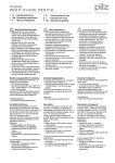
Fig. 2 bis Fig. 9 sind Anschlussbeispiele.
Beachten Sie bei Fig. 2: Das Gerät startet bei
Spannungsausfall und -wiederkehr automatisch. Verhindern Sie einen unerwarteten
Wiederanlauf durch externe Schaltungsmaßnahmen.
In Fig. 2...Fig. 9 are connection examples.
Please note for Fig. 2: the device starts
automatically after loss of power. You should
prevent an unintended start-up by using
external circuitry measures.
Les figures 2 à 9 représentent les différents
câblages possibles du PNOZ X2.7P/PNOZ
X2.8P.
Dans le cas de la figure 2, l’appareil se
réarme automatiquement après une
coupure et une remise sous tension. Evitez
tout risque de redémarrage par un câblage
externe approprié.
Wieder aktivieren
• Eingangskreis schließen.
• Bei manuellem Start ohne Überwachung
Taster zwischen S12 und S34 betätigen.
• Bei manuellem Start mit Überwachung
Taster zwischen S12 und S34 frühestens
110 ms nach dem Schließen der NOTAUS-Kontakte betätigen.
Die Statusanzeigen leuchten wieder, der
Eingangskreis ist aktiviert.
S11 S12 S21 S12 oder/or/ou S52
S11 S12 S21 S12 oder/or/ou S52
S1
S1
S12 S52 S22 S34
Fig. 2: nur bei PNOP X2.8P:
Eingangskreis einkanalig, automat. Start/
only PNOZ X2.8P: Single-channel input
circuit, automatic reset/ PNOP X2.8P
uniquement : Commande par 1 canal,
validation automatique
S3
S12 S52 S22 S34
Fig. 3: Eingangskreis einkanalig, manueller
Start/Single-channel input circuit, manual
reset/Commande par 1 canal, réarmement
manuel
-4-
S11 S11 S21 S12
S1
S3
S12 S52 S22 S34
Fig. 4: Eingangskreis zweikanalig, ohne
Querschlusserkennung, manueller Start/
Two-channel input circuit, no short circuit
detection, manual reset/Commande par 2
canaux, sans détection de court-circuit,
réarmement manuel
S11 S21 S12 S12 oder/or/ou S52
S11
S12
S11
S11
S21
S12
S1
S1
S3
S12
S21
S12
S11
S3
S3
S2
S12 S22 S52 S34
S22
Fig. 5: Schutztürsteuerung einkanalig,
manueller Start/Single-channel safety gate
control, manual reset/Surveillance de
protecteur, commande par 1 canal,
réarmement manuel
S52
S52
S34
Fig. 6: Schutztürsteuerung zweikanalig, mit
Querschlusserkennung, manueller Start/
Two-channel safety gate control, with short
circuit detection, manual reset/Surveillance
de protecteur, commande par 2 canaux,
avec détection de court-circuit, réarmement
manuel
S12
13
S11 S11 S21 S12
K5
BWS
K5
24 V DC
K6
S3
S34
Fig. 7: Schutztürsteuerung zweikanalig,
ohne Querschlusserkennung, manueller
Start/Two channel safety gate control,
no s/c detection, manual reset /Surveillance
de protecteur, commande par 2 canaux,
sans détection de court-circuit, réarmement
manuel
S1/S2: NOT-AUS- bzw. Schutztürschalter/
Emergency Stop Button, Safety
Gate Limit Switch/Poussoir AU,
détecteurs de position
S3:
Starttaster/Reset button/Poussoir de
réarmement
betätigtes Element/Switch activated/
élément actionné
S3
14
K5
S12 S52 S22 S34
K6
K6
S34
Fig. 8: Auswertung von OSSDs einer
vorgeschalteten BWS, zweikanalig,
Querschlusserkennung durch BWS,
manueller Start/Dual-channel light curtain
control, short circuit detection via ESPE,
manual reset/Commande par 2 canaux par
barrage immatériel , réarmement manuel
S22
Tür nicht geschlossen/Gate open/
porte ouverte
Tür geschlossen/Gate closed/porte
fermée
Fig. 9: Anschlussbeispiel für externe
Schütze, einkanalig, automatischer Start/
Connection example for external
contactors/relays, single-channel, automatic
reset/Branche-ment contacteurs externes,
commande par 1 canal, validation
automatique
Fehler - Störungen
Faults
Erreurs - Défaillances
• Erdschluss und Querschluss:
Die Versorgungsspannung bricht
zusammen und die Sicherheitskontakte
werden über eine elektronische Sicherung geöffnet. Nach Wegfall der Störungsursache und Abschalten der
Versorgungsspannung für ca. 1 Minute ist
das Gerät wieder betriebsbereit.
• Fehlfunktionen der Kontakte: Bei verschweißten Kontakten ist nach Öffnen
des Eingangskreises keine neue Aktivierung möglich.
• LED "Power" leuchtet nicht: Kurzschluss
oder Versorgungsspannung fehlt
• Earth fault and short circuit detection:
Supply voltage fails and the safety
contacts are opened via an electronic
fuse. Once the cause of the fault has
been removed and operating voltage is
switched off, the unit will be ready for
operation after approximately 1 minute.
• Contact failure: In the case of welded
contacts, no further activation is possible
following an opening of the input circuit.
• LED "Power" is not illuminated if shortcircuit or the supply voltage is lost.
• Défaut de masse et détection des courtscircuits :
La tension d’alimentation chute et les
contacts de sécurité sont ouverts par un
fusible électronique. Une fois la cause du
défaut éliminée et la tension
d’alimentation coupée, l’appareil est à
nouveau prêt à fonctionner après environ
1 minute.
• Défaut de fonctionnement des contacts
de sortie: en cas de soudage d’un contact
lors de l’ouverture du circuit d’entrée, un
nouvel réarmement est impossible.
• LED "Power" éteinte: tension
d'alimentation non présente ou courtcircuit interne.
-5-
Abmessungen in mm (")/Dimensions in mm (")/Dimensions en mm (")
Gehäuse mit steckbaren Schraubklemmen/
Housing with plug-in screw terminals/
Boîtier avec borniers débrochables à vis
121 (4.76")
121 (4.76")
Gehäuse mit steckbaren Käfigzugfederklemmen/
Housing with plug-in cage clamp terminals/
Boîtier avec borniers débrochables à ressort/
22,5
(0.88")
75 (2.95")
87 (3.42")
22,5
(0.88")
75 (2.95")
87 (3.42")
94 (3.70")
101 (3.98")
Steckbare Klemmen abziehen
Remove plug-in terminals
Démonter les borniers débrochables
Schraubendreher in Gehäuseaussparung
hinter der Klemme ansetzen und Klemme
heraushebeln.
Klemmen nicht an den Kabeln abziehen!
Insert screwdriver into the cut-out of the
housing behind the terminal and lever the
terminal.
Do not remove the terminals by pulling the
cables!
Placer un tournevis derrière les bornes et
sortir le bornier.
Ne pas retirer les borniers en tirant sur les
câbles !
How to remove the terminals using a screw
terminal as an example
Démontage d’un bornier à vis
Abziehen der Klemmen am Beispiel einer
Schraubklemme
Technische Daten
Technical Data
Caractéristiques techniques
Versorgungsspannung UB
Spannungstoleranz
Leistungsaufnahme bei UB
Operating Voltage UB
Voltage Tolerance
Power Consumption at U B
Tension d’alimentation UB
Plage de la tension d’alimentation
Consommation pour UB
Frequenzbereich
Restwelligkeit
Spannung und Strom an
Eingangskreis
Start- und Rückführkreis
Frequency Range
Residual Ripple
Voltage and Current at
Input circuit
Reset circuit and feedback loop
24 V AC/DC
-15 ... +10 %
AC: 3,5 VA;
DC: 2,0 W
50 ... 60 Hz
DC: 160 %
Fréquence
Ondulation résiduelle
Tension et courant du
Circuit d’entrée
UB = 24 V DC: 30 mA
Circuit de réarmement et boucle de UB = 24 V DC: 15 mA
retour
UB = 24 V DC: 50 mA
Ausgangskontakte nach EN 954-1
Output Contacts to EN 954-1
Contacts de sortie d'après EN 954-1
Sicherheitskontakte (S), Kategorie 4 Safety contacts N/O, category 4
contacts de sécurité (F), catégorie 4 2
Gebrauchskategorie nach
Utilization category to
Catégorie d’utilisation d'après
EN 60947-4-1
EN 60947-4-1
EN 60947-4-1
AC1: 240 V/0,01 ... 6 A/
1500 VA
DC1: 24 V/0,01 ... 6 A/
150 W
EN 60947-5-1(DC13: 6
EN 60947-5-1(DC13: 6 cycles/min) EN 60947-5-1(DC13: 6
AC15: 230 V/5 A;
Schaltspiele)
manoeuvres/min)
DC13: 24 V/4 A
Kontaktmaterial
Contact material
Matériau contact
AgSnO2+ 0,2 µm Au
-6-
Kontaktabsicherung extern nach
EN 60 947-5-1
Schmelzsicherung flink
Schmelzsicherung träge
Sicherungsautomat
Charakteristik
Max. Gesamtleitungswiderstand Rlmax
Eingangskreise
einkanalig DC
einkanalig AC
zweikanalig ohne
Querschlusserkennung DC
zweikanalig ohne
Querschlusserkennung AC
zweikanalig mit
Querschlusserkennung DC
zweikanalig mit
Querschlusserkennung AC
Einschaltverzögerung
PNOZ X2.8P
Automatischer Start
Automatischer Start nach Netz-EIN
Manueller Start
External Contact Fuse Protection to
EN 60 947-5-1
Blow-out fuse quick
Blow-out fuse slow
Safety cut-out
Cvaracteristic
Max. overall cable resistance Rlmax
input circuits
Single-channel DC
Single-channel AC
Dual-channel without detection of
shorts across contacts DC
Dual-channel without detection of
shorts across contacts AC
Dual-channel with detection of
shorts across contacts DC
Dual-channel with detection of
shorts across contacts AC
Switch-on delay
PNOZ X2.8P
Automatic reset
automatic reset after Power ON
Manual reset
PNOZ X2.7P
Überwachter Start
Rückfallverzögerung
bei NOT-AUS
bei Netzausfall
Wiederbereitschaftszeit bei max.
Schaltfrequenz 1/s
nach NOT-AUS
nach Netzausfall
Gleichzeitigkeit Kanal 1 und 2
Wartezeit bei überwachtem Start
PNOZ X2.7P
Monitored manual reset
Delay-on De-Energisation
at E-STOP
with power failure
Recovery time at max. switching
frequency 1/s
after E-STOP
after power failure
Simultaneity channel 1 and 2
Waiting period on monitored reset
Überbrückung bei
Spannungseinbrüchen
EMV
Max. supply interruption before deenergisations
EMC
Protection des contacts
EN 60 947-5-1
Fusibles rapide
Fusibles normal
Dijoncteur
Caractéristique
Résistance de câblage totale max.
Rlmax circuits d'entrée
Commande par 1 canal DC
Commande par 1 canal AC
Commande par 2 canaux sans
détection des court-circuits DC
Commande par 2 canaux sans
détection des court-circuits AC
Commande par 2 canaux avec
détection des court-circuits DC
Commande par 2 canaux avec
détection des court-circuits AC
Temps de réarmement
PNOZ X2.8P
Réarmement automatique
réarmement automatique après
mise sous tension
Réarmement manuel
PNOZ X2.7P
Réarmement manuel auto-contrôlé
Temps de retombée
en cas d'arrêt d'urgence
en cas de coupure d'alimentation
Temps de remise en service en cas de
fréquence de commutation max. 1/s
arrêt d'urgence
après une coupure d'alimentation
Désynchronisme canal 1 et 2
Temps d’attente en cas d’un
démarrage surveillé
Tenue aux micro-coupures
The version of the standards current at 11/03
shall apply
-7-
50 Ohm
200 Ohm
100 Ohm
320 Ohm
15 Ohm
25 Ohm
typ. 200 ms, max. 350 ms
typ. 210 ms, max. 400 ms
typ. 100 ms, max. 350 ms
typ. 120 ms, max. 150 ms
typ. 30 ms, max. 50 ms
typ.: 12 ms, max.: 30 ms
typ.: 50 ms, max.: 80 ms
50 ms
150 ms
∞
110 ms
10 ms
EN 60947-5-1,
EN 61000-6-2
CEM
Schwingungen nach EN 60068-2-6 Vibration to EN 60068-2-6
Vibrations d'après EN 60068-2-6
Frequenz
Frequency
Frequence
Amplitude
Amplitude
Amplitude
Klimabeanspruchung
Climate Suitability
Conditions climatiques
Luft- und Kriechstrecken
Airgap Creepage
Cheminement et claquage
Umgebungstemperatur
Operating Temperature
Température d’utilisation
Lagertemperatur
Storage Temperature
Température de stockage
Schutzart
Protection
Indice de protection
Einbauraum (z. B. Schaltschrank)
Mounting (eg. panel)
Lieu d'implantation (ex. armoire)
Gehäuse
Housing
Boîtier
Klemmenbereich
Terminals
Bornes
Gehäusematerial
Housing material
Matériau du boîtier
Gehäuse
Housing
Boîtier
Front
Front panel
Face avant
Max.Querschnitt des Außenleiters
Max. cable cross section (screw
Max. capacité de raccordement
(Schraubklemmen)
terminals)
(borniers à vis)
1 Leiter, flexibel
1 core, flexible
1 conducteur souple
2 Leiter gleichen Querschnitts, flexi- 2 core, same cross section flexible
2 conducteurs de même diamètre
bel mit Aderendhülse, ohne
with crimp connectors, without
souple avec embout, sans chapeau
Kunststoffhülse
insulating sleeve
plastique
ohne Aderendhülse oder mit TWIN- without crimp connectors or with
souple sans embout ou avec
Aderendhülse
TWIN crimp connectors
embout TWIN
Max.Querschnitt des Außenleiters
Max. cable cross section (cage clamp Max. capacité de raccordement
(Käfigzugfederklemmen)
terminals)
(borniers à ressort)
flexibel ohne Aderendhülse
flexible without crimp connectors
souple sans embout
Gehäuse mit Käfigzugfederklemmen Housing with cage clamp terminals Boîtier avec borniers à ressort
Abisolierlänge
Stripping length
Longueur de dénudage
Klemmstellen pro Anschluss
Termination points per connection
Bornes par raccordement
Anzugsdrehmoment für
Torque setting for screw terminals
Couple de serrage (borniers à vis)
Schraubklemmen
Abmessungen (Schraubklemmen)
Dimensions H x W x D (screw
Dimensions (borniers à vis) H x P x L
HxBxT
terminals)
Abmessungen
Dimensions (cage clamp terminals) Dimensions (borniers à ressort) H x
(Käfigzugfederklemmen) H x B x T
HxWxD
LxP
Einbaulage
Fitting Position
Position de travail
Gewicht
Weight
Poids
Es gelten die 11/03 aktuellen Ausgaben der
Normen
6A
4A
24 V AC/DC: 4 A
B/C
10 ... 55 Hz
0,35 mm
EN 60068-2-78
VDE 0110-1
-10 ... + 55 °C
-40 ... +85 °C
IP54
IP40
IP20
PPO UL 94 V0
ABS UL 94 V0
0,25 ... 2,5 mm2
0,25 ... 1 mm2
0,2 ... 1,5 mm2
0,2 ... 1,5 mm2
8 mm
2
0,5 Nm
94 x 22,5 x 121 mm
101 x 22,5 x 121 mm
beliebig
190 g
Se référer à la version des normes en vigeur
au 11/03.
Max. Dauerstrom bei gleichzeitiger Belastung mehrerer Kontakte/Total current switching capability across
all contacts/Intensité commutée max. en cas de charge sur plusieurs contacts
Anzahl der Kontakte/number of contacts/nombre des contacts
Imax bei 24 V AC/DC-Geräten/with 24 V AC/DC units/pour les relais 24 C AC/DC
3
5A
2
6A
1
6A
Lebensdauer der Ausgangsrelais/Service Life of Output relays/Durée de vie des relais de sortie
AC1: 230 V
DC13: 24 V
DC1: 24 V
AC15: 230 V
1
0.1
10
100
1000
Schaltspielzahl x 103
Cycles x 103
Nombre de manvres x 103
10000
A Pilz Ges.m.b.H., ✆ 01 7986263-0, Fax: 01 7986264 AUS Pilz Australia, ✆ 03 95446300, Fax: 03 95446311 B L Pilz Belgium, ✆ 09 3217570,
Fax: 09 3217571
BR Pilz do Brasil, ✆ 11 4337-1241, Fax: 11 4337-1242
CH Pilz lndustrieelektronik GmbH, ✆ 062 88979-30, Fax: 062 88979-40
DK Pilz Skandinavien K/S, ✆ 74436332, Fax: 74436342 E Pilz lndustrieelektronik S.L., ✆ 938497433, Fax: 938497544 F Pilz France Electronic,
✆ 03 88104000, Fax: 03 88108000 FIN Pilz Skandinavien K/S, ✆ 09 27093700, Fax: 09 27093709
GB Pilz Automation Technology, ✆ 01536 460766,
Fax: 01536 460866
I Pilz ltalia Srl, ✆ 031 789511, Fax: 031 789555 IRL Pilz Ireland Industrial Automation, ✆ 021 4346535, Fax: 021 4804994
J Pilz Japan Co., Ltd., ✆ 045 471-2281, Fax: 045 471-2283 MEX Pilz de Mexico, S. de R.L. de C.V., ✆ 55 5572 1300, Fax: 55 5572 4194
NL Pilz Nederland, ✆ 0347 320477, Fax: 0347 320485 NZ Pilz New Zealand, ✆ 09- 6345-350, Fax: 09-6345-352 P Pilz Industrieelektronik S.L.,
✆ 229407594, Fax: 229407595
PRC Pilz China Representative Office, ✆ 021 62494658, Fax: 021 62491300 ROK Pilz Korea, ✆ 031 8159541,
Fax: 031 8159542
SE Pilz Skandinavien K/S, ✆ 0300 13990, Fax: 0300 30740 TR Pilz Elektronik Güvenlik Ürünleri ve Hizmetleri Tic. Ltd. Şti.,
✆ 0224 2360180, Fax: 0224 2360184
USA Pilz Automation Safety L.P., ✆ 734 354-0272, Fax: 734 354-3355 www www.pilz.com
D Pilz GmbH & Co. KG, Sichere Automation, Felix-Wankel-Straße 2, 73760 Ostfildern, Deutschland, ✆ +49 711 3409-0, Fax: +49 711 3409-133,
E-Mail: [email protected]
-8-
20 813-03-12/04 Printed in Germany
Nennbetriebstrom (A)
Nominal operating current (A)
Courant coupé (A)
10
20813-03
PNOZ X2.7P / PNOZ X2.8P
4
4
4
E
I
NL
Instrucciones de uso
Istruzioni per luso
Gebruiksaanwijzing
Normas de seguridad
Norme di sicurezza
Veiligheidsvoorschriften
• El dispositivo tiene que ser instalado y
puesto en funcionamiento exclusivamente
por un electricista especializado o por
personas que estén familiarizadas tanto
con estas instrucciones de uso como con
las prescripciones vigentes relativas a la
seguridad en el trabajo y a la prevención
de accidentes. Hay que observar tanto las
prescripciones VDE como las prescripciones locales, especialmente en lo que se
refiere a las medidas de protección.
• Durante el transporte, el almacenaje y el
funcionamiento hay que atenerse a las
condiciones expresadas en EN 60068-2-6
(véanse los datos técnicos). Una vez
concluida su vida útil, elimine el dispositivo de forma apropiada.
• La garantía se pierde en caso de que se
abra la carcasa o se lleven a cabo
modificaciones por cuenta propia.
• Hay que cuidar de que haya un
conexionado de seguridad suficiente en
todos los contactos de salida con cargas
capacitivas e inductivas.
• Estas instrucciones de uso sirven de guía
y se deben conservar para una futura
utilización.
• La función de seguridad debe ejecutarse
por lo menos una vez al mes.
• Il dispositivo può venire installato e messo
in funzione solo da tecnici di elettronica
oppure persone addestrate che conoscono
bene le presenti istruzioni per l’uso e le
disposizioni vigenti riguardo alla sicurezza
di lavoro e all’antinfortunistica. Osservare
le disposizioni della VDE nonché le norme
locali, soprattutto per quanto riguarda le
misure preventive di protezione.
• Durante il trasporto, l’immagazzinamento
e il funzionamento attenersi alle condizioni prescritte dalla norma EN 60068-2-6
(v. Dati tecnici). Al termine della propria
durata, smaltire il dispositivo in conformità
alle norme vigenti.
• Se viene aperta la custodia oppure se
vengono apportate delle modifiche in
proprio decade qualsiasi diritto di
garanzia.
• Preoccuparsi che tutti i contatti di uscita
sui carichi capacitivi e induttivi siano
dotati di un circuito sicurezza sufficiente.
• La presente descrizione funge da
manuale di istruzioni e va conservata in
previsione di un futuro impiego.
• La funzione di sicurezza deve essere
attivata almeno una volta al mese.
• Het apparaat mag uitsluitend worden
geïnstalleerd en in bedrijf genomen door
een elektrotechnicus of een persoon die
vertrouwd is met deze gebruiksaanwijzing
en met de geldende voorschriften op het
gebied van arbeidsveiligheid en
ongevallenpreventie. Neem de van
toepassing zijnde Europese richtlijnen en
de plaatselijke voorschriften in acht, in het
bijzonder m.b.t. veiligheidsmaatregelen.
• Neem bij transport, bij opslag en in bedrijf
de richtlijnen volgens EN 60068-2-6 in
acht (zie technische gegevens). Verwijder
na afloop van de levensduur van het
apparaat alle afvalstoffen op een juiste
manier.
• Het openen van de behuizing of het
eigenmachtig veranderen van de
schakeling heeft verlies van de garantie
tot gevolg.
• Zorgt u bij capacitieve of inductieve
belasting van de uitgangscontacten voor
adequate contactbeschermingsmaatregelen.
• Deze gebruiksaanwijzing geeft instructies
en dient voor toekomstig gebruik bewaard
te worden.
• De veiligheidsfunctie moet ten minste een
keer per maand geactiveerd worden.
Campo de aplicación adecuado
Uso previsto
Gebruik volgens de voorschriften
El dispositivo de seguridad PNOZ X2.7P/
PNOZ X2.8P está concebido para ser
empleado en
• dispositivos de PARADA DE EMERGENCIA
• circuitos de seguridad según EN 60204-1
(VDE 0113-1), p. ej. en dispositivos de
protección sin contacto
Il modulo di sicurezza PNOZ X2.7P/
PNOZ X2.8P è concepito per essere
utilizzato in
• dispositivi di arresto di emergenza
• circuiti elettrici di sicurezza secondo la
norma EN 60204-1 (VDE 0113-1), ad es.
nelle barriere fotoelettriche
Het veiligheidsrelais PNOZ X2.7P/
PNOZ X2.8P is bestemd voor gebruik in
• noodstopvoorzieningen
• veiligheidscircuits volgens EN 60204-1
(VDE 0113-1), b.v. bij contactloos
werkende beveiligingsinrichtingen
Descripción del dispositivo
Descrizione
Apparaatbeschrijving
El dispositivo de seguridad PNOZ X2.7P/
PNOZ X2.8P está montado dentro de una
carcasa P-99. Se puede poner en servicio
con 24 V de tensión continua o con 24 V de
tensión alterna.
Características:
• Salidas de relé: 3 contactos de seguridad
(normalmente abiertos) y un contacto
auxiliar (normalmente cerrado), de guía
forzosa
• Posibilidad de conexión para pulsador de
PARADA DE EMERGENCIA, interruptor
límite de puerta protectora, BWS
(dispositivo de protección sin contacto) y
pulsador de rearme
PNOZ X2.7P: pulsador de rearme
supervisado
PNOZ X2.8P: posibilidad de rearme
automático
• Indicación de estado
• Supervisión posible de contactores
externos
• Sin separación galvánica
El dispositivo cumple los requisitos de
seguridad siguientes:
• El circuito está estructurado de modo
redundante con autosupervisión (EN 954-1,
categoría 4).
Il modulo di sicurezza PNOZ X2.7P/
PNOZ X2.8P è sistemato in una custodia
P-99. Si può azionare con corrente alternata
a 24 V o con corrente continua a 24 V.
Caratteristiche:
• Uscite relè: 3 contatti di sicurezza (NA) e
un contatto ausiliario (NC) con contatti
guidati
• Possibilità di collegamento per pulsante di
arresto di emergenza, finecorsa riparo
mobile, barriera fotoelettrica, pulsante di
start
PNOZ X2.7P: pulsante di start controllato
PNOZ X2.8P: possibile start automatico
• Visualizzazione di stato
• Possibile controllo di relè esterni
• Nessuna separazione galvanica
Il dispositivo elettrico risponde ai seguenti
requisiti di sicurezza:
• Il circuito è strutturato in modo ridondante
con autocontrollo (EN 954-1, categoria 4).
Het veiligheidsrelais PNOZ X2.7P/
PNOZ X2.8P is in een P-99-behuizing
ondergebracht. Het relais kan met 24 V
wisselspanning of met 24 V gelijkspanning
gebruikt worden.
Kenmerken:
• Relaisuitgangen: 3 veiligheidscontacten
(maakcontacten) en 1 hulpcontact
(verbreekcontact), mechanisch gedwongen
• Aansluitmogelijkheid voor noodstopknoppen, hekschakelaars, lichtschermen
en de startknop
PNOZ X2.7P bewaakte startknop
PNOZ X2.8P: automatische start mogelijk
• Statusweergave
• Bewaking van externe magneetschakelaars mogelijk
• geen galvanische scheiding
Het relais voldoet aan de volgende
veiligheidseisen:
• De schakeling is redundant met zelfbewaking opgebouwd (EN 954-1,
categorie 4).
-1-
• El equipo de seguridad permanece activo
aunque falle uno de los componentes.
• En cada ciclo de conexión/desconexión de
la máquina, se verifica automáticamente,
si los relés de la instalación de seguridad
se abren y se cierran correctamente.
• Il dispositivo di sicurezza funziona anche
in caso di guasto di un componente.
• Per ciascun ciclo di inserimentodisinserimento della macchina,
viene eseguita la verifica automatica della
corretta apertura e chiusura dei relè del
dispositivo di sicurezza.
• Ook bij uitvallen van een component blijft
de veiligheidsschakeling werken.
• Bij elke aan/uit-cyclus van de machine
wordt automatisch getest of de relaiscontacten van de veiligheidsvoorziening
correct openen en sluiten.
Descripción del funcionamiento
Descrizione del funzionamento
Functiebeschrijving
Il modulo PNOZ X2.7P/PNOZ X2.8P serve
per interrompere per motivi di sicurezza un
circuito elettrico di sicurezza. Dopo l’immissione della tensione di alimentazione il LED
"Power" è acceso. Il dispositivo è pronto per
il funzionamento quando il circuito di start
S12-S34 è chiuso (start automatico) oppure
quando viene chiuso e nuovamente aperto
(start manuale).
• Il circuito di ingresso è chiuso (p. es.
pulsante di arresto d’emergenza non
azionato):
i relè K1 e K2 si eccitano e si
automantengono. Le visualizzazioni di
stato "CH.1" e "CH.2" per i canali 1 e 2 si
illuminano. I contatti di sicurezza 13-14,
23-24, 33-34 sono chiusi, il contatto
ausiliario 41-42 è aperto.
• Il circuito di ingresso viene aperto (p. es.
pulsante di arresto di emergenza
azionato):
i relè K1 e K2 si diseccitano. Le
visualizzazioni di stato "CH.1" e "CH.2" si
spengono. I contatti di sicurezza 13-14,
23-24, 33-34 vengono aperti in modo
ridondante, il contatto ausiliario
41-42 viene chiuso.
Het relais type PNOZ X2.7P/PNOZ X2.8P
dient om een veiligheidscircuit veilig te
onderbreken. Na het inschakelen van de
voedingsspanning licht de LED "Power" op.
Het apparaat is bedrijfsklaar wanneer het
startcircuit S12-S34 gesloten wordt (automatische start) of gesloten en weer
geopend wordt (handmatige start).
• Ingangscircuit gesloten (b.v. noodstopknop niet bediend):
Relais K1 en K2 worden bekrachtigd en
nemen zichzelf over. De status-LED’s
"CH.1" en "CH.2" voor kanaal 1 en
kanaal 2 lichten op. De veiligheidscontacten 13-14, 23-24, 33-34 zijn
gesloten, het hulpcontact 41-42 is
geopend.
• Ingangscircuit wordt geopend (b.v.
noodstopknop bediend):
Relais K1 en K2 vallen af. De statusLED’s "CH.1" en "CH.2" doven. De
veiligheidscontacten 13-14, 23-24, 33-34
worden redundant geopend, het hulpcontact 41-42 wordt gesloten.
El dispositivo PNOZ X2.7P/PNOZ X2.8P
sirve para interrumpir por razones de
seguridad un circuito de seguridad. El LED
"POWER" se ilumina cuando se aplica la
tensión de alimentación. El dispositivo se
encuentra listo para el servicio cuando el
circuito de rearme S12-S34 se ha cerrado
(rearme automático) o se ha vuelto a abrir
después de cerrarse (rearme manual).
• Circuito de entrada cerrado (p. ej.
pulsador de PARADA DE EMERGENCIA
no accionado):
Los relés K1 y K2 se activan y se mantienen por sí mismos. Los indicadores de
estado "CH.1" y "CH.2" para el canal 1 y
2 se iluminan. Los contactos de seguridad 13-14, 23-24, 33-34 están cerrados;
el contacto auxiliar 41-42 está abierto.
• Se abre el circuito de entrada (p. ej. al
accionar el pulsador de PARADA DE
EMERCENCIA):
Los relés K1 y K2 regresan a la posición
de reposo. Los indicadores de estado
"CH.1" y "CH.2" se apagan. Los contactos
de seguridad 13-14, 23-24, 33-34 se
abren de modo redundante, el contacto
auxiliar 41-42 está cerrado.
UB
A1 (L+) A2 (L-)
~
S11 S12
S34
13 23 33 41
S52
+
K1
CH2
S21
Start
Unit
CH1
K2
S22
14 24 34 42
Fig. 1: Esquema de conexiones internas/schema di collegamento interno/intern schema
Modos de funcionamiento
• Funcionamiento monocanal: conexionado
de entrada según VDE 0113 y EN 60204,
sin redundancia en el circuito de entrada,
se detectan los contactos a tierra en el
circuito del pulsador.
• Funcionamiento bicanal sin detección de
derivación: circuito de entrada redundante, se detectan los cortocircuitos y los
contactos a tierra en el circuito del
pulsador.
• Funcionamiento bicanal con detección de
derivación: circuito de entrada redundante, se detectan los cortocircuitos y los
contactos a tierra en el circuito del
pulsador, así como las derivaciones entre
los contactos de pulsadores.
• Sólo PNOZ X2.8P: rearme automático: el
dispositivo se activa tan pronto como el
circuito de entrada se cierra.
• Rearme manual: el dispositivo se activa
cuando el circuito de rearme S12-S34 se
cierra. De este modo se descarta un
Modi operativi
• Funzionamento a singolo canale:
cablaggio di ingresso a norma VDE 0113
ed EN 60204, nessuna ridondanza nel
circuito di ingresso; vengono identificati i
guasti a terra nel circuito del pulsante.
• Modalità bicanale senza riconoscimento
di cortocircuito incrociato: un circuito di
ingresso ridondante, cortocircuiti e guasti
a terra nel circuito del pulsante vengono
riconosciuti.
• Modalità bicanale senza riconoscimento
di cortocircuito incrociato: circuito di
ingresso ridondante; vengono identificati
cortocircuiti e guasti a terra nel circuito
del pulsante e i cortocircuiti incrociati tra i
contatti dei pulsanti.
• Solo PNOZ X2.8P: start automatico: il
dispositivo è attivo non appena il circuito
di ingresso viene chiuso.
• Start manuale: il dispositivo è attivo,
quando il circuito di start S12-S34 è
chiuso. In questo modo si esclude uno
-2-
Bedrijfsmodi
• Eenkanalig bedrijf: ingangsschakeling
volgens VDE 0113 en EN 60204, geen
redundantie in het ingangscircuit,
aardsluitingen in het ingangscircuit
worden gedetecteerd.
• Tweekanalig bedrijf zonder detectie van
onderlinge sluiting: redundant ingangscircuit, kortsluitingen en aardsluitingen in
het ingangscircuit worden gedetecteerd.
• Tweekanalig bedrijf met detectie van
onderlinge sluiting: redundant ingangscircuit, kortsluitingen en aardsluitingen in
het ingangscircuit en onderlinge sluitingen
tussen de ingangscontacten worden
gedetecteerd.
• Alleen PNOZ X2.8P: Automatische start:
apparaat is actief, zodra het ingangscircuit gesloten is.
• Handmatige start: apparaat is actief
wanneer het startcircuit S12-S34
gesloten is. Daardoor is een automatische activering van het relais na uitvallen
rearme automático del dispositivo si se
produce un corte y restablecimiento de la
tensión.
• Sólo PNOZ X2.7P: rearme manual
supervisado: el dispositivo se activa
solamente cuando el circuito de rearme
S12-S34 se cierra transcurridos, como
mínimo, 110 ms después de haberse
cerrado los contactos de PARADA DE
EMERGENCIA. De esta manera se
excluye la posibilidad de una activación
automática y un puenteo del pulsador de
rearme.
• Multiplicación y refuerzo de contactos
mediante la conexión de contactores
externos.
start automatico del relè dopo l’interruzione e il ripristino dell’alimentazione di
corrente.
• Solo PNOZ X2.7P: start manuale,
controllato: il dispositivo è attivo solamente quando il circuito di start S12-S34
viene chiuso non prima di 110 ms
dall’interruzione dei contatti di arresto di
emergenza. In tal modo si esclude
un’attivazione automatica e un’esclusione
del pulsante di start.
• Aumento del numero e della portata dei
contatti tramite collegamento di relè
esterni
en terugkeren van de spanning
uitgesloten.
• Alleen PNOZ X2.7P: Handmatige start,
bewaakt: apparaat is alleen actief,
wanneer het startcircuit S12-S34 ten
vroegste 110 ms na sluiten van de
noodstopcontacten gesloten wordt.
Daardoor is automatische activering door
overbrugging van de startknop uitgesloten.
• Contactvermeerdering en -versterking
door aansluiten van externe magneetschakelaars
Montaje
Montaggio
Montage
Monte el dispositivo en un armario de
distribución con un grado de protección de
IP 54 como mínimo. El dispositivo dispone
en su parte trasera de un elemento de
encaje para fijarlo a una guía normalizada.
Al montarlo en una guía portadora vertical
(35 mm) hay que asegurar el dispositivo por
medio de un elemento de soporte, tal como
un soporte o un ángulo final.
Il modulo di sicurezza deve essere montato
in un armadio elettrico con un tipo di
protezione corrispondente almeno al grado
IP 54. Un dispositivo a scatto sul retro del
dispositivo serve per fissare una guida DIN.
Al montaggio fissare il dispositivo su una
guida verticale (35 mm) a mezzo di un supporto quale p. es. staffa di fissaggio o angolo
terminale.
Bouw het veiligheidsrelais in een schakelkast in met een beschermingsgraad van
minimaal IP54. Bevestiging op een DIN-rail
is mogelijk via de daarvoor bestemde
relaisvoet op de achterzijde van het
apparaat. Bij montage op een verticale
draagrail (35 mm) moet het apparaat worden
vastgezet met een eindsteun.
Puesta en marcha
Messa in funzione
Ingebruikneming
Al poner en marcha el dispositivo hay que
tener en cuenta los siguientes aspectos:
• Cablear el dispositivo solamente con la
tensión desconectada.
• Utilizar para las líneas material de
alambre de cobre con una resistencia a la
temperatura de 60/75 °C.
• Respetar sin falta las indicaciones del
capítulo "Datos técnicos".
• Sólo los contactos de salida 13-14, 23-24,
33-34 son contactos de seguridad. El
contacto de salida 41-42 es un contacto
auxiliar (p. ej. para visualización).
• Se debe poner en el circuito un fusible
antes de los contactos de salida
(véanse los datos técnicos), para evitar
que los contactos puedan quedar
soldados.
• Cálculo de la longitud máx. de línea Imáx
(circuito de entrada):
Imax =
Rlmax
Rl / km
Rlmáx = resistencia máx. del total de la línea
(circuito de entrada)
Rl /km = resistencia de línea/km
Importante para la detección de
derivación:
Dado que esta función no es a prueba de
errores, Pilz la comprueba durante el
control final.
Si se corre el peligro de superar las
longitudes de línea, recomendamos
realizar la siguiente comprobación una
vez instalado el dispositivo:
1. Dispositivo listo para el servicio
(contactos de salida cerrados).
2. Cortocircuitar los bornes de ensayo
S12, S22 para la comprobación de
derivación.
3. El fusible en el dispositivo tiene que
dispararse y los contactos de salida se
tienen que abrir. Las líneas con
longitudes próximas a la máxima
pueden retardar hasta 2 minutos el
disparo del fusible.
4. Rearmar el fusible: eliminar el cortocircuito y desconectar la tensión de
alimentación durante aprox. 1 minuto.
Alla messa in funzione occorre osservare
quanto segue:
• Cablare il dispositivo solo in assenza di
tensione!
• Per i cavi utilizzare materiale in filo di
rame con una resistenza termica intorno
ai 60/75 °C.
• Attenersi assolutamente alle indicazioni
riportate al capitolo "Dati tecnici".
• Solo i contatti di uscita 13-14, 23-24,
33-34 sono contatti di sicurezza. Il
contatto di uscita 41-42 è un contatto
ausiliario (p. es. per visualizzazione).
• Per evitare la saldatura dei contatti,
collegare un fusibile (vedi dati tecnici)
a monte dei contatti di uscita.
• Calcolo della lunghezza max. conduttore
Imax(circuito di ingresso):
Imax =
Rlmax
Neem bij ingebruikneming het volgende in
acht:
• Het apparaat alleen in de spanningsloze
toestand aansluiten!
• Kabelmateriaal uit koperdraad met een
temperatuurbestendigheid van 60/75 °C
gebruiken.
• Aanwijzingen in het hoofdstuk "Technische gegevens" beslist opvolgen.
• Alleen de uitgangscontacten 13-14,
23-24, 33-34 zijn veiligheidscontacten.
Uitgangscontact 41-42 is een hulpcontact
(b.v. voor signalering).
• Uitgangscontacten afzekeren (zie
technische gegeven) om het verkleven
van de contacten te voorkomen.
• Berekening van de max. kabellengte Imax
(ingangscircuit):
Imax =
Rl / km
Rlmax
Rl / km
Rlmax = resistenza totale conduttore max.
(Circuito d’ingresso)
Rl /km = resistenza del cavo/km
Rlmax = max. weerstand totale kabel
(ingangscircuit)
Rl /km = kabelweerstand/km
Importante per riconoscimento
cortocircuiti incrociati:
Poiché questa funzione non è protetta
dagli errori, essa viene testata dalla Pilz
durante il controllo finale.
Se sussiste il pericolo che le lunghezze
dei conduttori vengano superate,
consigliamo, dopo l’installazione del
dispositivo, di effettuare il seguente
controllo:
1. Dispositivo pronto per il funzionamento
(contatti di uscita chiusi).
2. Cortocircuitare i morsetti di test S12,
S22 per il controllo dei cortocircuiti
incrociati.
3. Il fusibile nel dispositivo deve scattare
e i contatti di uscita devono aprirsi. Le
lunghezze dei cavi nell’ordine di
grandezza della lunghezza massima
possono ritardare lo scatto del fusibile
fino a 2 minuti.
4. Resettare il fusibile: rimuovere il
cortocircuito e la tensione di
alimentazione per 1 minuto circa.
Belangrijk voor detectie van onderlinge
sluiting:
Omdat deze functie niet enkelfoutveilig is,
wordt deze door Pilz tijdens de eindcontrole getest.
Als het gevaar bestaat dat de max.
kabellengte overschreden wordt, adviseren wij de volgende controle na de
installatie van het apparaat:
1. Apparaat bedrijfsklaar (uitgangscontacten gesloten)
2. De testklemmen S12-S22 kortsluiten
om de detectie van onderlinge sluiting
te testen.
3. De zekering in het apparaat moet
geactiveerd worden en de uitgangscontacten moeten opengaan. Kabellengten van ongeveer de maximale
lengte kunnen het activeren van de
zekering met max. 2 minuten vertragen.
4. Zekering resetten: de kortsluiting
ongedaan maken en de voedingsspanning voor ca. 1 minuut
uitschakelen.
-3-
Proceso:
• Tensión de alimentación:
- Aplicar tensión en los bornes A1 y A2.
• Circuito de rearme:
- Sólo PNOZ X2.8P: rearme automático:
puentear S12-S34.
- Rearme manual sin supervisión:
conectar pulsador a S12-S34.
- Sólo PNOZ X2.7P: rearme manual con
supervisión: conectar el pulsador a
S12-S34.
• Circuito de entrada:
- Monocanal: puentear S12-S52 y
S21-S22. Conectar el contacto
normalmente cerrado del elemento de
disparo a S11 y S12.
- Bicanal con detección de derivación:
puentear S21-S22. Conectar el
contacto normalmente cerrado del
elemento de disparo a S11-S12 y
S11-S52.
- Bicanal con detección de derivación:
puentear S11-S52. Conectar el
contacto normalmente cerrado del
elemento de disparo a S11-S12 y
S21-S22.
• Circuito de realimentación: conectar los
contactores externos en serie hacia el
circuito de rearme S12-S34.
Cuando la tensión de alimentación está
activada y se cumple la condición de
rearme, los contactos de seguridad están
cerrados y el contacto auxiliar 41-42,
abierto. Los indicadores de estado "CH.1" y
"CH.2" para el canal 1 y 2 se iluminan. El
dispositivo se encuentra listo para el
servicio.
Cuando se abre el circuito de entrada, se
abren los contactos de seguridad 13-14,
23-24, 33-34 y el contacto auxiliar 41-42 se
cierra. Los indicadores de estado "CH.1" y
"CH.2" se apagan.
Procedura:
• Tensione di alimentazione:
- Applicare la tensione di alimentazione
ai morsetti A1 e A2.
• Circuito di start:
- solo PNOZ X2.8P: Start automatico:
cavallottare S12-S34.
- Start manuale senza controllo:
collegare il pulsante con S12-S34
- solo PNOZ X2.7P: Start manuale
controllato: collegare il pulsante con
S12-S34.
• Circuito d’ingresso:
- Canale singolo: cavallottare S12-S52 e
S21-S22. Collegare il contatto NC
dell’elemento di commutazione con
S11 e S12.
- Bicanale senza riconoscimento di
cortocircuito incrociato: cavallottare
S21-S22. Collegare il contatto NC
dell’elemento di commutazione con
S11-S12 ed S12-S52.
- Bicanale con riconoscimento di
cortocircuito incrociato: cavallottare
S11-S52. Collegare il contatto NC
dell’elemento di commutazione con
S11-S12 ed S21-S22.
• Circuito di retroazione: collegare i
relè esterni in serie al circuito di start
S12-S34.
Se la tensione di alimentazione è attivata e
la condizione per lo start è soddisfatta, i
contatti di sicurezza sono chiusi e il contatto
ausiliario 41-42 è aperto. Le visualizzazioni
di stato "CH.1", "CH.2" per il canale 1 e il
canale 2 si illuminano. Il dispositivo è pronto
per l’uso.
Se il circuito di ingresso viene aperto, i
contatti di sicurezza 13-14, 23-24, 33-34 si
aprono e il contatto ausiliario 41-42 si
chiude. Le visualizzazioni di stato "CH.1",
"CH.2" si spengono.
Activar de nuevo
• Cerrar el circuito de entrada.
• En caso de rearme manual sin supervisión, accionar el pulsador entre S12 y
S34.
• En caso de rearme supervisado, accionar
el pulsador entre S12 y S34 transcurridos
110 ms como mínimo después de
haberse cerrado los contactos de
PARADA DE EMERGENCIA.
Los indicadores de estado vuelven a
iluminarse, el circuito de entrada está
activado.
Riattivazione
• Chiudere il circuito di ingresso.
• In caso di start manuale senza controllo,
azionare il pulsante tra S12 e S34.
• In caso di start manuale controllato,
azionare il pulsante tra S12 e S34 non
prima di 110 ms dalla chiusura dei
contatti di arresto d’emergenza.
Le visualizzazioni di stato si accendono
nuovamente, il circuito di ingresso viene
attivato.
Aplicación
Utilizzo
Toepassing
En la figura 2 hasta la figura 9 se muestran
ejemplos de conexión.
Observe en la figura 2 que el dispositivo
arranca automáticamente después de un
corte y restablecimiento de la tensión. Tome
medidas de conexión externas para evitar
que la máquina se vuelva a poner en marcha
inesperadamente.
Dalla fig. 2 fino alla fig. 9 sono esempi di
collegamento.
Per la fig. 2 considerare che il dispositivo nel
caso di interruzione e ripristino dell’alimentazione di corrente si riavvia automaticamente.
Evitare un riavviamento inaspettato mediante
appositi dispositivi di accensione esterni.
Afb. 2 t/m afb. 9 zijn aansluitvoorbeelden.
Opgelet bij afb. 2: het apparaat start
automatisch bij uitvallen en terugkeren van
de spanning. Vermijd een onverwacht
heraanlopen door maatregelen in de externe
schakeling.
-4-
Verloop:
• Voedingsspanning:
- Voedingsspanning op klemmen A1 en
A2 aansluiten.
• Startcircuit:
- Alleen PNOZ X2.8P: Automatische
start: S12-S34 verbinden.
- Handmatige start zonder bewaking:
knop op S12-S34 aansluiten
- Alleen PNOZ X2.7P: Handmatige start
met bewaking: Sluit knop aan op
S12-S34.
• Ingangscircuit:
- Eenkanalig: S12-S52 en S21-S22
verbinden. Verbreekcontact van
bedieningsorgaan op S11 en S12
aansluiten.
- Tweekanalig zonder detectie van
onderlinge sluiting: S21-S22 verbinden.
Verbreekcontact van bedieningsorgaan
op S11-S12 en S11-S52 aansluiten.
- Tweekanalig met detectie van onderlinge sluiting: S11-S52 verbinden.
Verbreekcontact van bedieningsorgaan
op S11-S12 en S21-S22 aansluiten.
• Terugkoppelcircuit: Verbreekcontacten
van externe magneetschakelaars in serie
met het startcircuit S12-S34 aansluiten.
Als de voedingsspanning ingeschakeld is en
aan de startvoorwaarde voldaan is, zijn de
veiligheidscontacten gesloten en het
hulpcontact 41-42 is geopend. De statusLED’s "CH.1", "CH.2" voor kanaal 1 en
kanaal 2 lichten op. Het apparaat is
bedrijfsklaar.
Als het ingangscircuit geopend wordt, gaan
de veiligheidscontacten 13-14, 23-24, 33-34
open en sluit het hulpcontact 41-42. De
status-LED’s "CH.1", "CH.2" doven.
Opnieuw activeren
• Ingangscircuit sluiten.
• Bij handmatige start zonder bewaking de
knop tussen S12 en S34 bedienen.
• Bij handmatige start met bewaking knop
tussen S12 en S34 ten vroegste 110 ms
na sluiten van de noodstopcontacten
bedienen.
De status-LED’s lichten weer op, het
ingangscircuit is geactiveerd.
S11 S12 S21 S12 o/o/of S52
S11 S12 S21 S12 o/o/of S52
S1
S1
S1
S3
S12 S52 S22 S34
S12 S52 S22 S34
Fig. 2: sólo con PNOZ X2.8P:
circuito de entrada monocanal, rearme
automático/solo per PNOP X2.8P:
Circuito di ingresso a singolo canale, start
automatico/Alleen bij PNOP X2.8P:
Eenkanalig ingangscircuit, automat. start
Fig. 3: circuito de entrada monocanal,
rearme manual/Circuito di ingresso a
singolo canale, start manuale/Eenkanalig
ingangscircuit, handmatige start
S11 S21 S12 S12 o/o/of S52
S3
S12 S52 S22 S34
Fig. 4: circuito de entrada bicanal, sin
detección de derivación, rearme manual/
Circuito di ingresso bicanale, senza
riconoscimento di cortocircuito incrociato,
start manuale/Tweekanalig ingangscircuit,
zonder detectie van onderlinge sluiting,
handmatige start
S11
S12
S11
S11
S11 S11 S21 S12
S21
S12
S1
S1
S3
S12
S21
S12
S11
S3
S3
S2
S12 S22 S52
S34
Fig. 5: control de puerta de protección
monocanal, rearme manual/Controllo riparo
mobile a singolo canale, start manuale/
Eenkanalige hekbewaking, handmatige
start
S11 S11 S21 S12
S22
S52
S34
Fig. 6: control de puerta de protección
bicanal, con detección de derivación,
rearme manual/Controllo riparo mobile
bicanale, con riconoscimento di cortocircuito
incrociato, start manuale/Tweekanalige
hekbewaking, met detectie van onderlinge
sluiting, handmatige start
24 V DC
BWS
S52
S12
K5
K5
K6
Fig. 8: evaluación de OSSD de un BWS
intercalado, bicanal, detección de derivación mediante BWS, rearme manual/
Valutazione degli OSSD di una barriera
fotoelettrica di protezione collegata,
bicanale, riconoscimento del cortocircuito
incrociato mediante barriera fotoelettrica,
start manuale/Evaluatie van OSSDs van
een voorgeschakelde CWB, tweekanalig,
detecteren van onderlinge sluitingen door
CWB, handmatige start
S34
Fig. 7: control de puerta de protección
bicanal, sin detección de derivación,
rearme manual/Controllo riparo mobile
bicanale, senza riconoscimento di
cortocircuito incrociato, start manuale/
Tweekanalige hekbewaking, zonder
detectie van onderlinge sluiting, handmatige start
13
S3
S12 S52 S22 S34
S22
S3
14
K5
K6
K6
S1/S2: PARADA DE EMERGENCIA o bien
interruptor de puerta protectora/
Interruttore dell’ARRESTO DI
EMERGENZA, ovvero del riparo
mobile/Noodstop- of hekschakelaar
S3:
Pulsador de rearme/Pulsante di
start/Startknop
Elemento accionado/Elemento
azionato/Bekrachtigd element
S34
Fig. 9: ejemplo de conexión para
contactores externos, monocanal, rearme
automático/Esempio di collegamento per
relè esterni, a singolo canale, start
automatico/Aansluitvoorbeeld van externe
magneetschakelaars, eenkanalig, automatische start
Puerta no cerrada/Porta non chiusa/
Hek open
Puerta cerrada/Porta chiusa/Hek
gesloten
Errores - Fallos
Errori - Guasti
Fouten - Storingen
• Contacto a tierra y derivación:
La tensión de alimentación se colapsa y
los contactos de seguridad se abren por
medio de un fusible electrónico. Una vez
eliminada la causa del error y desconectada la tensión de alimentación, el
dispositivo se encuentra de nuevo listo
para el servicio después de aprox.
1 minuto.
• Funcionamiento defectuoso de los
contactos: en caso de contactos fundidos,
después de abrir el circuito de entrada no
es posible ninguna nueva activación.
• El LED "POWER" no se ilumina: cortocircuito o no hay tensión de alimentación.
• Guasto a terra e cortocircuito incrociato:
la tensione di alimentazione viene
interrotta e i contatti di sicurezza si
aprono mediante un fusibile elettronico.
Dopo l’eliminazione dell’origine dei guasti
e mantenendo la tensione di alimentazione per 1 minuto circa il dispositivo è
nuovamente pronto per il funzionamento.
• Funzionamento errato dei contatti: in caso
di saldatura dei contatti, dopo l’apertura
del circuito di ingresso non è possibile
nessuna nuova attivazione.
• Il LED "POWER" non è acceso:
cortocircuito o tensione di alimentazione
mancante.
• Aardsluiting en onderlinge sluiting:
De voedingsspanning valt uit en de
veiligheidscontacten worden via een
elektronische zekering geopend. Na het
wegvallen van de storingsoorzaak en het
uitschakelen van de voedingsspanning
voor ca. 1 minuut is het apparaat weer
bedrijfsklaar.
• Contactfout: Bij verkleefde contacten is
na openen van het ingangscircuit geen
nieuwe activering mogelijk.
• LED "Power" licht niet op: kortsluiting of
voedingsspanning ontbreekt.
-5-
Dimensiones en mm (")/Dimensioni in mm (")/Afmetingen in mm (")
Carcasa con bornes de tornillo enchufables/
Custodia con morsetti a vite a innesto/
Behuizing met steekbare schroefklemmen
121 (4.76")
121 (4.76")
Carcasa con bornes de resorte enchufables/Custodia con
morsetti con molla a gabbia ad innesto/Behuizing met
steekbare veerklemmen
22,5
(0.88")
75 (2.95")
87 (3.42")
75 (2.95")
87 (3.42")
94 (3.70")
22,5
(0.88")
101 (3.98")
Extraer los bornes enchufables
Staccare i morsetti ad innesto
Steekbare klemmen verwijderen
Insertar el destornillador en la abertura de la
carcasa que hay detrás del borne y sacarlo
haciendo palanca.
No tirar del cable para extraer el borne.
Infilare il cacciavite nella fessura della
custodia dietro al morsetto e staccare il
morsetto facendo leva.
Non staccare i morsetti tirando dai cavi!
Schroevendraaier in behuizingsuitsparing
achter de klem zetten en klem uitwippen.
Klemmen niet aan de kabels uittrekken!
Separazione di un morsetto sull’esempio di
un morsetto a vite
Klemmen uittrekken met schroefklem als
voorbeeld
Ejemplo de cómo extraer un borne de tornillo
Datos técnicos
Dati tecnici
Technische gegevens
Tensión de alimentación UB
Tolerancia de tensión
Consumo de energía con UB
Tensione di alimentazione UB
Tolleranza di tensione
Potenza assorbita con UB
Voedingsspanning UB
Spanningstolerantie
Opgenomen vermogen bij UB
Margen de frecuencias
Campo di frequenza
Ondulación residual
Ondulazione residua
Tensión y corriente en
Tensione e corrente su
circuito de entrada
circuito d’ingresso
circuito de rearme y realimentación circuito di start e di retroazione
Frequentiebereik
Rimpelspanning
Spanning en stroom op
Ingangscircuit
Start- en terugkoppelcircuit
24 V AC/DC
-15 ... +10 %
AC: 3,5 VA;
DC: 2,0 W
50 ... 60 Hz
DC: 160 %
UB = 24 V DC: 30 mA
UB = 24 V DC: 15 mA
UB = 24 V DC: 50 mA
Contactos de salida según EN 954-1 Contatti di uscita conformi alla norma EN 954-1 Uitgangscontacten volgens EN 954-1
contactos de seguridad
Contatti di sicurezza (NA), categoria 4
Veiligheidscontacten (M),
2
(normalmente abiertos), categoría 4
categorie 4
AC1: 240 V/0,01 ... 6 A/
Categoría de uso según
Categoria d’uso in conformità a
Gebruikscategorie volgens
1500 VA
EN 60947-4-1
EN 60947-4-1
EN 60947-4-1
DC1: 24 V/0,01 ... 6 A/
150 W
AC15: 230 V/5 A;
EN 60947-5-1 (DC13: 6 cicli di
EN 60947-5-1(DC13: 6
DC13: 24 V/4 A
EN 60947-5-1 (CC13: 6 ciclos)
commutazione)
schakelingen)
AgSnO2+ 0,2 µm Au
Material de los contactos
Materiale di contatto
Contactmateriaal
-6-
Protección externa de los contactos
según EN 60 947-5-1
fusible de acción rápida
fusible de acción lenta
fusible automático
característica
Resistencia máxima del total de la
línea Rlmáx Circuitos de entrada
monocanal CC
monocanal CA
bicanal sin
detección de derivación CC
bicanal sin
detección de derivación CA
bicanal con
detección de derivación CC
bicanal con
detección de derivación CA
Retardo a la conexión
PNOZ X2.8P
rearme automático
rearme automático tras conexión de red
Fusibile dei contatti, esterno,
secondo norma EN 60 947-5-1
Fusibile rapido
Fusibile ritardato
Interruttore automatico
Caratteristiche
Resistenza totale del conduttore
max. Rlmax circuiti d’ingresso
a singolo canale DC
a singolo canale AC
bicanale senza riconoscimento
cortocircuiti incrociati DC
bicanale senza riconoscimento
cortocircuiti incrociati AC
bicanale con riconoscimento
cortocircuiti incrociati DC
bicanale con riconoscimento
cortocircuiti incrociati AC
Ritardo d’inserzione
PNOZ X2.8P
Start automatico
Start automatico dopo attivazione
dell’alimentazione di rete (ON)
Start manuale
Contactafzekering extern volgens
EN 60 947-5-1
Smeltzekering snel
6A
Smeltzekering traag
4A
Zekeringautomaat
24 V AC/DC: 4 A
Karakteristiek
B/C
Max. weerstand totale kabel Rlmax
ingangscircuits
Eenkanalig DC
50 Ohm
Eenkanalig AC
200 Ohm
Tweekanalig zonder detectie
van onderlinge sluiting DC
100 Ohm
Tweekanalig zonder detectie
van onderlinge sluiting AC
320 Ohm
Tweekanalig met detectie van
onderlinge sluiting DC
15 Ohm
Tweekanalig met detectie van
onderlinge sluiting AC
25 Ohm
Inschakelvertraging
PNOZ X2.8P
Automatische start
typ. 200 ms, max. 350 ms
Automatische start na
netinschakeling
typ. 210 ms, max. 400 ms
Handmatige start
typ. 100 ms, max. 350 ms
PNOZ X2.7P
rearme supervisado
Retardo a la desconexión
en caso de PARADA DE EMERGENCIA
en caso de interrupción del suministro
eléctrico
Tiempo de recuperación con una
frecuencia máxima de conmutación de 1/s
tras PARADA DE EMERGENCIA
tras interrupción del suministro eléctrico
Simultaneidad canal 1 y 2
Tiempo de espera en caso de rearme
supervisado
Inmunidad a cortes de tensión
CEM
PNOZ X2.7P
Start controllato
Ritardo di sgancio
in caso di arresto di emergenza
PNOZ X2.7P
Bewaakte start
Afvalvertraging
Bij noodstop
typ. 120 ms, max. 150 ms
typ. 30 ms, max. 50 ms
in caso di perdita di alimentazione
Tempo di ripristino per frequenza di
commutazione max. 1/s
dopo ARRESTO DI EMERGENZA
dopo perdita di alimentazione
Simultaneità canali 1 e 2
Tempo di attesa per start controllato
Bij uitvallen spanning
Resettijd bij max. schakelfrequentie 1/s
na noodstop
na uitvallen spanning
Gelijktijdigheid kanaal 1 en 2
Wachttijd bij bewaakte start
typ.: 50 ms, max.: 80 ms
Ininfluenza mancanza tensione
CEM
Vibraciones según EN 60068-2-6
longitud de pelar
bornes por conexión
Par de apriete para los bornes de
tornillo
Dimensiones (bornes de tornillo)
Al x An x Pr
Dimensiones (bornes de resorte)
Al x An x Pr
Posición de montaje
Oscillazioni secondo la norma
EN 60068-2-6
Frequenza
Ampiezza
Sollecitazione climatica
Caratteristiche dielettriche
Temperatura ambiente
Temperatura di magazzinaggio
Grado di protezione
Spazio di montaggio (p. es. quadro
elettrico ad armadio)
Custodia
Zona morsetti
Materiale impiegato per la custodia
Custodia
Parte frontale
Sezione massima del conduttore
esterno (morsetti a vite)
1 conduttore, flessibile
2 conduttori dello stesso diametro,
flessibile con capocorda, senza
guaina in plastica
senza capocorda o con capocorda
TWIN
Sezione massima del conduttore
esterno (morsetti con molla a gabbia)
flessibile senza capocorda
Custodia con morsetti con molla a
gabbia
Lunghezza di spelatura
Prese morsetti per connessione
Coppia di serraggio per i morsetti
a vite
Misure (morsetti a vite)
altezza x larghezza x profondità
Misure (morsetti con molla a gabbia)
altezza x larghezza x profondità
Posizione di montaggio
Maximale spanningsonderbreking 10 ms
EMC
EN 60947-5-1,
EN 61000-6-2
Trillingsbestendigheid
volgens EN 60068-2-6
10 ... 55 Hz
Frequentie
Amplitude
0,35 mm
Klimaatcondities
EN 60068-2-78
Lucht- en kruipwegen
VDE 0110-1
Omgevingstemperatuur
-10 ... + 55 °C
Opslagtemperatuur
-40 ... +85 °C
Beschermingsgraad
Peso
Peso
rearme manual
frecuencia
amplitud
Condiciones ambientales
Distancias de fuga y dispersión superficial
Temperatura ambiente
Temperatura de almacenaje
Grado de protección
lugar de montaje (p. ej. armario de
distribución)
carcasa
zona de bornes
Material de la carcasa
carcasa
frente
Sección máx. del conductor exterior
(bornes de tornillo)
1 conductor flexible
2 conductores multifilares de la misma
sección, flexibles con terminal, sin
revestimiento de plástico
sin terminal o con terminal
TWIN
Sección máx. del conductor exterior
(bornes de resorte)
flexible sin terminal
Carcasa con bornes de resorte
Se aplica la edición vigente de las
normas a 11/03
typ.: 12 ms, max.: 30 ms
50 ms
150 ms
∞
110 ms
Inbouwruimte (b.v. schakelkast)IP54
Behuizing
IP40
Aansluitklemmen
IP20
Behuizingsmateriaal
Behuizing
PPO UL 94 V0
Front
ABS UL 94 V0
Max. doorsnede van de aansluitkabels (schroefklemmen)
1 draad, flexibel
0,25 ... 2,5 mm2
2 draden met dezelfde doorsnede, flexibel met adereindhuls, zonder kunststofhuls
0,25 ... 1 mm2
zonder adereindhuls of met
TWIN-adereindhuls
0,2 ... 1,5 mm2
Max. doorsnede van de aansluitkabels (veerklemmen)
flexibel zonder adereindhuls
0,2 ... 1,5 mm2
Behuizing met veerklemmen
Afstriplengte
Klemmen per aansluiting
Aanhaalmoment voor
schroefklemmen
Afmetingen (schroefklemmen)
hxbxd
Afmetingen (veerklemmen)
hxbxd
Inbouwpositie
Gewicht
8 mm
2
0,5 Nm
94 x 22,5 x 121 mm
101 x 22,5 x 121 mm
cualquiera/a scelta/
willekeurig
190 g
Sono valide le versioni
De per 11/03 actuele uitgaven van
aggiornate all’11/03 delle norme de normen zijn van toepassing
-7-
Corriente permanente máx. en caso de carga simultánea de varios contactos/Corrente permanente massima
sollecitando diversi contatti contemporaneamente/Max. continustroom bij gelijktijdige belasting van meerdere
contacten
Número de contactos/Numero dei contatti/Aantal contacten
Imáx con dispositivos de 24 V CA/CC/Imax per dispositivi a 24 V AC/DC/
Imax bij 24 V AC/DC-apparaten
3
2
1
5A
6A
6A
Vida útil de los relés de salida/Durata dei relè di uscita/Levensduur van de uitgangsrelais
AC1: 230 V
DC13: 24 V
DC1: 24 V
AC15: 230 V
1
0.1
10
100
1000
Número de ciclos x 103
Numero dei cicli di commutazione x 103
Aantal schakelingen x 103
10000
A Pilz Ges.m.b.H., ✆ 01 7986263-0, Fax: 01 7986264 AUS Pilz Australia, ✆ 03 95446300, Fax: 03 95446311 B L Pilz Belgium, ✆ 09 3217570,
Fax: 09 3217571
BR Pilz do Brasil, ✆ 11 4337-1241, Fax: 11 4337-1242
CH Pilz lndustrieelektronik GmbH, ✆ 062 88979-30, Fax: 062 88979-40
DK Pilz Skandinavien K/S, ✆ 74436332, Fax: 74436342 E Pilz lndustrieelektronik S.L., ✆ 938497433, Fax: 938497544 F Pilz France Electronic,
✆ 03 88104000, Fax: 03 88108000 FIN Pilz Skandinavien K/S, ✆ 09 27093700, Fax: 09 27093709
GB Pilz Automation Technology, ✆ 01536 460766,
Fax: 01536 460866
I Pilz ltalia Srl, ✆ 031 789511, Fax: 031 789555 IRL Pilz Ireland Industrial Automation, ✆ 021 4346535, Fax: 021 4804994
J Pilz Japan Co., Ltd., ✆ 045 471-2281, Fax: 045 471-2283 MEX Pilz de Mexico, S. de R.L. de C.V., ✆ 55 5572 1300, Fax: 55 5572 4194
NL Pilz Nederland, ✆ 0347 320477, Fax: 0347 320485 NZ Pilz New Zealand, ✆ 09- 6345-350, Fax: 09-6345-352 P Pilz Industrieelektronik S.L.,
✆ 229407594, Fax: 229407595
PRC Pilz China Representative Office, ✆ 021 62494658, Fax: 021 62491300 ROK Pilz Korea, ✆ 031 8159541,
Fax: 031 8159542
SE Pilz Skandinavien K/S, ✆ 0300 13990, Fax: 0300 30740 TR Pilz Elektronik Güvenlik Ürünleri ve Hizmetleri Tic. Ltd. Şti.,
✆ 0224 2360180, Fax: 0224 2360184
USA Pilz Automation Safety L.P., ✆ 734 354-0272, Fax: 734 354-3355 www www.pilz.com
D Pilz GmbH & Co. KG, Sichere Automation, Felix-Wankel-Straße 2, 73760 Ostfildern, Deutschland, ✆ +49 711 3409-0, Fax: +49 711 3409-133,
E-Mail: [email protected]
-8-
20 813-03-12/04 Printed in Germany
Corriente de trabajo nominal (A)
Corrente di esercizio nominale (A)
Nominale bedrijfsstroom (A)
10