1
TYPE
Ø PAD mm
PAD THREAD
VELCRO
WORKING PRESSURE bar/PSIG
AIR CONSUMPTION MAX l/min
POWER Hp
RPM
WEIGHT kg
SPEED CONTROL
ENGLISH
IPH 75 024 K
75
3/8” 24T Male
IPH 75 038 KR
75
3/8” 24T Male
IPH 75 050 KR
75
3/8” 24T Male
6,2/90
420
0,45
2400
1,1
-
6,2/90
644
0,45
3800
1
6,2/90
644
0,45
5000
1
·
PICTOGRAPH
Read the following instruction first before operating
the product.
Important safety indications
Use personal
protective equipment.
WARNINGS
The safety and accident prevention instructions are reported in
the “SAFETY INSTRUCTION” booklet which is an integral part
of these documents.
This operating instructions manual indicates the additional
information required for the specific use of the tool.
CORRECT USAGE
This tool is designed to be used as a polisher. Read all the
warnings, instructions, indications provided on drawings
and specifications supplied with this tool. Failure to comply
with all the instructions provided below may serius injuries.
This tool is not intended to be used for smoothing, metal
brushing and cutting operations. The use of this tool for unintended applications may cause hazards and injuries to people.
The tool must be used with accessories that have been specifically designed or reccomended by the manifacturer. The
fixing of the acessory to the tool does not guarantee a safe
operation. The rated speed of the accessories must be at
least equivalent to the maximum speed specified on the tool.
Using the accessories at speeds above the rated one, may
cause them to break or be projected into he air. The external
diameter and tockness ohf the accessories must match the
specifications of the tool. Accessoris with incorrect dimension cannot be adequately protected or controlled. The configuration of accessories must match the tool. The use of accessories that cannot be perfectly fitted on the tool may result
in imbalance, excessive vibrations and in the impossibility of
controlling the tool. Do not use damaged accesories. Before
use, inspect all the accessories. Inspect the supporting pads
and verify there are no cracks, tears or excessive wear. If
the tool or accessory has fallen, verfy that it is not demaged
or install a new accerrory. After inspecting or installing an
accessory, test the operation of the tool at maximum speed
and whitout load for one minute, keeping at a safety distance. If the accessories are demaged, they will break during this
test.
·
·
·
·
6
LH180P
180
M14
·
6,2/90
750
0,45
2500
2,3
·
SPECIFIC SAFETY WARNINGS
Verify that no loosened part of the polishing tool shroud or
the locking ties can rotate freely. Safety position or cut all
the loosened fixing wires. Loosened or revolving fixing wires
may twist around the operator’s finers or get caught by the
work piece being machined.
STARTING UP
The compressed air production and distribution system
must meet the requirements indicated by the data on the
identification plate (1).
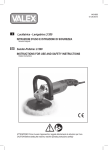
TOOL ASSEMBLY
The tool is supplied without the compressed air conection (5);
the user can use either a quick release coupling or hose type
connection according to his needs, purke they have an ole of
air passing mm. 8. In the latter case the air line must be fixed
to the nozzle by a hose clip.
In the latter case the air line must be fixed to the nozzle by a
hose clip.
ACCESSORIES ASSEMBLY
PAD IPH 75 024 K - IPH 75 038 KR - IPH 75 050 KR:
Block the spindle (4) using the wrench (7) and screw the pad
(9).
PAD LH180P:
Screw plate pad holder (9) over spindle shaft (4) while preventing it from moving or stop movement by enabling lock button
(14).
POLISHING FOAM
Fix by pressure the polishing foam on the support (9).
START AND STOPPING
- Starting: push the control lever (2) towards the body of the
tool and keep it pressed moving the safety lever (3).
- Stopping: release the control lever.
The tool continues to rotate after it is turned off.
SELECTING RPM
The number of revolutions can be adjusted by using the speed
control (6) from MAX to OFF. The choice of speed depends on
the characteristics of the material to be worked.
3 AXIS VIBRATION LEVEL
UNCERTAINTY
m/s2
K
ACCESSORIES DISASSEMBLY
3 AXIS VIBRATION LEVEL
UNCERTAINTY
m/s2
K
PAD IPH 75 024 K - IPH 75 038 KR - IPH 75 050 KR:
Block the spindle (4) using the wrench (7) and dismount the
pad (9).
PAD LH180P:
- Lock the spindle by pressing button (14), while at the same
time rotating the pad (9) until it locks position.
- dismount the pad (9).
POLISHING FOAM
Remove the polishing foam and fix the new one.
ever press the button to lock the pad or pas until the
N
tool has stopped moving and is perfectly stationary;
the gear box or the push button pin could be broken
and the guarantee would be invalidated.
ALLOWED ACCESSORIES
IPH 75 024 K - IPH 75 038 KR- IPH 75 050 KR
Polishing foam Ø 75-100 mm for pad Ø 75 mm.
LH180P
Polishing foam and foam support pad up to Ø 200 mm max.
NOISE EMISSION VALUES
Detected noise emission values comply with the following
standard:
UNI EN ISO 15744
SOUND PRESSURE LEVEL
SOUND POWER LEVEL
UNCERTAINTY
dB(A)
dB(A)
K
IPH 75 024 K
81,6
92,6
3
SOUND PRESSURE LEVEL
SOUND POWER LEVEL
UNCERTAINTY
dB(A)
dB(A)
K
IPH 75 038 KR
84,1
95,1
3
SOUND PRESSURE LEVEL
SOUND POWER LEVEL
UNCERTAINTY
dB(A)
dB(A)
K
IPH 75 050 KR
83,9
94,9
3
SOUND PRESSURE LEVEL
SOUND POWER LEVEL
UNCERTAINTY
dB(A)
dB(A)
K
LH180P
85,9
96,9
3
IPH 75 050 KR
1,304
0,624
LH180P
2,85
1,347
Displayed emission values are comparative and are to be employed for a provisional assessment of the operator’s risk exposure
during the work period. Appropriate evaluation of work period
must also include tool’s idle and stop periods.
These emission values represent the tool’s main applications.
If the tool is used for other applications, with other accessories,
or if it does not undergo regular maintenance, emission values
can significantly increase during operations.
All maintenance operations are carried out with the tool disconnected from the compressed air supply. At the end of each work
session, or when required, remove anydust from the body of the
tool using a jet of compressed air.
Lubricate the machine regularly (every 50 hours of operation) by inserting 2/3 drops of specific oil (synthetic oil without silicone, ISO 32) into the compressed air connection,
keeping the device in a vertical position, with the connection
facing upwards. After this operation, connect the machine
to the power supply and set it in motion for a few seconds.
Lubricate the machine asdescribed above before storing it for
long periods of inactivity. All damages deriving from incorrect
or inadequate lubrication are excluded from the warranty.
No other maintenance operations must be undertaken by the user.
Maintenance and cleaning of the inner parts, must be carried
out only by an authorized customer-service workshop.
DISPOSAL (WEEE DIRECTIVE)
At the end of its useful life, the product, pursuant to European Directive 2002/96/CE (WEEE) + 2003/108/
CE and its implementation in national law, must not be released into the environment or thrown away as domestic waste,
but must be disposed of at authorised recycling centres (contact
the relevant local authorities for a list of places where the product may be disposed of according to the law). Disposing of
the product correctly contributes to protecting human health and
safeguarding the environment. Any illegitimate disposal of the
product will be punishable by law.
CONFORMITY DECLARATION
We declare on our responsibility that the hand-held non-electric
tool, which is mentioned in the present operating manual,
is in conformity with the Essential Requirements
of Safety of the following Directive: 2006/42/CE, 2011/65/CE.
The tests have been carried out in accordance with the
European Harmonised standard UNI EN 792-8: 2008 + A1:2008.
S.p.A
Use ear protection!
THE PRESIDENT
G. Valentini
VIBRATION EMESSION VALUES
Detected vibration emission values comply with the following
standard:
EN ISO 28927-3; EN 28662-1
3 AXIS VIBRATION LEVEL
UNCERTAINTY
m/s2
K
IPH 75 024 K
2,345
1,136
3 AXIS VIBRATION LEVEL
UNCERTAINTY
m/s2
K
IPH 75 038 KR
1,362
0,36
IPH 75 024 K - IPH 75 038 KR
IPH 75 050 KR - LH180P
MAINTENANCE
RUPES S.p.A.
Via Marconi, 3A
20080 VERMEZZO (Mi) - Italy
Tel. +39 02 946941
Fax +39 02 94941040
Uff. Vendite e assistena clienti:
Tel. +39 02 94694312
e-mail: [email protected]
web: http://www.rupes.com
OTTOBRE 2012
TECHNICAL SPECIFICATIONS
4 - ILucidatrici
6 - GB Polisher
ISTRUZIONI ORIGINALI PER L’USO E LA MANUTENZIONE
OPERATING AND MAINTENANCE INSTRUCTIONS
IPH 75 024 K
DATI TECNICI
5
MODELLO
Ø PLATORELLO mm
FILETTO PLATORELLO
VELCRO
PRESSIONE DI ESERCIZIO bar/PSIG
CONSUMO ARIA MAX I/min
POTENZA Hp
RPM
PESO kg
REGOLAZIONE VELOCITÁ
1
2
3
ITALIANO
IPH 75 024 K
75
3/8” 24T Male
IPH 75 038 KR
75
3/8” 24T Male
IPH 75 050 KR
75
3/8” 24T Male
6,2/90
420
0,45
2400
1,1
-
6,2/90
644
0,45
3800
1
6,2/90
644
0,45
5000
1
·
SIMBOLI GRAFICI
7
4
9
5
6
1
AVVERTENZE GENERALI
IPH 75 038 KR
IPH 75 050 KR
Le istruzioni per la sicurezza e la prevenzione degli infortuni
sono riportate nel fascicolo “INDICAZIONI PER LA SICUREZZA” che costituisce parte integrante della presente documentazione. Il presente manuale d’istruzioni per l’uso riporta solamente le informazioni aggiuntive strettamente correlate all’uso
specifico della macchina.
2
3
UTILIZZO CONFORME AGLI SCOPI PREVISTI
8
4
7
9
LH180P
5
6
1
14
Leggere tutte queste istruzioni prima di azionare il
presente prodotto.
Indicazioni importanti per la sicurezza
dell’utilizzatore.
Utilizzare i dispositivi di protezione individuale.
2
3
8
4
9
Questo utensile è destinato a funzionare come lucidatrice.
Leggere tutti gli avvertimenti di sicurezza, le istruzioni, le
illustrazioni e le specifiche forniti con questo utensile. Il
mancato rispetto di tutte le istruzioni sotto riportate può causare un incidente grave. Le operazioni di molatura, levigatura, spazzolatura metallica o di taglio non sono previste
con questo utensile. Le operazioni per le quali non è previsto
l’utensile possono provocare un pericolo e causare danni alle
persone. Non utilizzare accessori non specificatamente
realizzati dal produttore di utensile e da lui consigliati. Il
semplice fatto che l’accessorio possa essere fissato al vostro
utensile non garantisce un funzionamento in tutta sicurezza.
La velocità nominale dell’accessorio deve essere almeno
pari alla velocità massima indicata sull’utensile. Gli accessori fatti funzionare a una velocità superiore a quella nominale possono rompersi ed essere proiettati in aria. Il diametro
esterno e lo spessore del vostro accessorio devono essere
adatti alle caratteristiche di capacità del vostro utensile.
Gli accessori che hanno dimensione non corrette possono
non essere protetti o controllati adeguatamente. La conformazione degli accessori deve adattarsi correttamente al
mandrino dell’utensile. Gli accessori dotati di fori dell’albero
che non corrispondono agli elementi di montaggio sull’utensile non rimarranno in equilibrio, vibreranno eccessivamente
e potranno provocare una perdita di controllo. Non usare un
accessorio danneggiato. Se l’utensile o l’accessorio ha subito una caduta, esaminare i danni eventuali o installare
un accessorio non danneggiato. Dopo aver esaminato e
installato un accessorio, mettetevi, insieme alle persone
7 a distanza dal piano dell’accessorio rotante e
presenti,
fate funzionare l’utensile alla velocità massima a vuoto per
un minuto. Gli accessori danneggiati si romperanno in genere
in questo periodo di prova.
·
·
·
·
4
LH180P
180
M14
·
6,2/90
750
0,45
2500
2,3
·
AVVERTENZE DI SICUREZZA SPECIFICHE
Non permettere ad alcuna parte allentata della cuffia
dell’accessorio di lucidatura ne alle stringhe di fissaggio di
girare liberamente.
Mettere in sicurezza o tagliare ogni fili di fissaggio allentato.
I fili di fissaggio allentati e in rotazione possono attorcigliarsi
sulle vostre dita oppure impigliarsi sul pezzo in lavorazione.
MESSA IN FUNZIONE
L’impianto di produzione e distribuzione di aria compressa deve corrispondere ai requisiti dei dati indicati sulla
targhetta di identificazione (1).
MONTAGGIO DELL’UTENSILE
La macchina viene fornita sprovvista del raccordo di (5); a
scelta dell’utilizzatore possono essere usati sia raccordi ad
innesto rapido sia portagomma adeguati purchè entrambi abbiano un foro di passaggio aria da mm. 8. Nel secondo caso
occorre fissare stabilmente con una fascetta stringitubo il tubo
di alimentazione al portagomma.
MONTAGGIO DEGLI ACCESSORI
REGOLAZIONE DEL NUMERO DI GIRI
La regolazione del numero dei giri si ottiene manovrando opportunamente il regolatore (6) da MAX a OFF. La scelta della
velocità va fatta in funzione delle caratteristiche del materiale
da lavorare.
SMONTAGGIO DEGLI ACCESSORI
PLATORELLO IPH 75 024 K - IPH 75 038 KR - IPH 75 050 KR:
Bloccare l’albero mandrino con la chiave (7) e svitare il platorello (9).
PLATORELLO LH180P
- Bloccare l’albero mandrino spingendo il pulsante (14) facendo contemporaneamente ruotare il platorello (9) finché se ne
avverta il blocco;
- svitare il platorello (9).
TAMPONE DI LUCIDATURA
Asportare a strappo il tampone usato e applicare il nuovo premendolo sul platorello.
Il pulsante di bloccaggio dell’albero mandrino non
deve mai essere premuto prima che l’utensile non sia
completamente fermo, pena la rottura della scatola
ingranaggi o del perno del pulsante e al conseguente
decadimento della garanzia.
ACCESSORI AMMESSI
IPH 75 024 K - IPH 75 038 KR- IPH 75 050 KR
Tamponi di lucidatura Ø 75-100 mm per platorelli Ø 75 mm.
LH180P
Piattelli portatamponi e tamponi fino a Ø 200 mm max.
VALORI DI EMISSIONE DI RUMOROSITÁ
Valori di emissione di rumorosità rilevati secondo le norme:
UNI EN ISO 15744
PLATORELLO IPH 75 024 K - IPH 75 038 KR - IPH 75 050 KR:
Bloccare l’albero mandrino con la chiave (7) e avvitare il
platorello (9)
LIVELLO DI PRESSIONE ACUSTICA
LIVELLO DI POTENZA SONORA
INCERTEZZA
dB(A)
dB(A)
K
IPH 75 024 K
81,6
92,6
3
PLATORELLO LH180P:
Avvitare il piattello porta tampone (9) sull’albero mandrino (4)
mantenendolo fermo con il pulsante di blocco (14).
TAMPONE DI LUCIDATURA
Far aderire mediante pressione il tampone di lucidatura al supporto (9).
LIVELLO DI PRESSIONE ACUSTICA
LIVELLO DI POTENZA SONORA
INCERTEZZA
dB(A)
dB(A)
K
IPH 75 038 KR
84,1
95,1
3
MESSA IN SERVIZIO
LIVELLO DI PRESSIONE ACUSTICA
LIVELLO DI POTENZA SONORA
INCERTEZZA
dB(A)
dB(A)
K
IPH 75 050 KR
83,9
94,9
3
- Avviamento: spingere la leva di comando (2) verso il corpo
macchina e mantenerla premuta agendo sulla leva di sicurezza (3);
- Arresto: rilasciare la leva di comando.
L’utensile continua per alcuni secondi a funzionare dopo
lo spegnimento!
LIVELLO DI PRESSIONE ACUSTICA
POTENZA SONORA
INCERTEZZA
dB(A)
dB(A)
K
LH180P
85,9
96,9
3
LIVELLO DI VIBRAZIONI SU TRE ASSI
INCERTEZZA
m/s2
K
LIVELLO DI VIBRAZIONI SU TRE ASSI
INCERTEZZA
m/s2
K
Valori di emissione di vibrazioni rilevati secondo le norme:
EN ISO 28927-3; EN 28662-1
LIVELLO DI VIBRAZIONI SU TRE ASSI
INCERTEZZA
m/s2
K
IPH 75 024 K
2,345
1,136
LIVELLO DI VIBRAZIONI SU TRE ASSI
INCERTEZZA
m/s2
K
IPH 75 038 KR
1,362
0,36
2,85
1,347
MANUTENZIONE
Tutte le operazioni vanno eseguite a macchina scollegata. A fine
lavoro, od in caso di necessità, spolverare con getto di aria compressa il corpo macchina.
Lubrificare periodicamente (ogni 50 ore di lavoro) la macchina inserendo 2/3 gocce d’olio per uso specifico (olio sintetico
senza silicone ISO 32) nell’attacco aria compressa dell’utensile
tenendolo stesso in posizione verticale con l’attacco in alto.
Dopo questa operazione collegare la macchina all’alimentazione e azionarla per alcuni secondi. Prima di riporre l’utensile per
un lungo periodo di inattività procedere all’operazione di lubrificazione come sopra descritto. Si escludono dalla garanzia tutti
i danni derivanti da una scorretta o inadeguata lubrificazione.
Non sono ammessi altri interventi da parte dell’utente.
Per la manutenzione e la periodica pulizia delle parti interne, come
cuscinetti, ingranaggi, etc. o altre necessità rivolgersi ai Centri di
Assistenza autorizzati
SMALTIMENTO (Direttiva RAEE)
Il prodotto, in ottemperanza alla Direttiva Europea 2002/96/
CE (RAEE) + 2003/108/CE e alla sua attuazione nel diritto nazionale, quando giunge a fine vita, non deve essere disperso
nell’ambiente o gettato tra i rifiuti domestici, ma deve esse smaltito presso i centri di raccolta differenziata autorizzati(contattare le
autorità locali competenti per conoscere dove smaltire il prodotto
secondo le norme di legge). Il corretto smaltimento del prodotto
contribuisce alla tutela della salute e alla salvaguardia dell’ambiente.
Lo smaltimento abusivo del prodotto comporta sanzioni a carico
dei trasgressori.
DICHIARAZIONE DI CONFORMITÀ
Dichiariamo sotto la nostra responsabilità che il prodotto, al quale
fa riferimento il presente manuale, è conforme ai requisiti essenziali
della Direttiva 2006/42/CE, 2011/65/CE.
Le prove/verifiche sono eseguite in conformità alle Normative
UNI EN 792-8: 2008 + A1:2008.
IL PRESIDENTE
G. Valentini
VALORI DI EMISSIONE DI VIBRAZIONI
LH180P
I valori di emissione indicati sono comparativi e utilizzabili per una
valutazione provvisoria dei rischi di esposizione dell’operatore
durante il periodo di lavoro. La corretta valutazione del periodo di
lavoro deve comprendere anche i tempi di funzionamento a vuoto
e di arresto dell’utensile. I valori di emissioni indicati sono rappresentativi delle principali applicazioni dell’utensile. Se l’utensile viene
utilizzato per altre applicazioni, con altri accessori o se non viene
sottoposto a regolare manutenzione, i valori di emissione possono
aumentare sensibilmente durante il funzionamento.
S.p.A
Utilizzare le cuffie di protezione!
IPH 75 050 KR
1,304
0,624
IPH 75 024 K
DATI TECNICI
5
MODELLO
Ø PLATORELLO mm
FILETTO PLATORELLO
VELCRO
PRESSIONE DI ESERCIZIO bar/PSIG
CONSUMO ARIA MAX I/min
POTENZA Hp
RPM
PESO kg
REGOLAZIONE VELOCITÁ
1
2
3
ITALIANO
IPH 75 024 K
75
3/8” 24T Male
IPH 75 038 KR
75
3/8” 24T Male
IPH 75 050 KR
75
3/8” 24T Male
6,2/90
420
0,45
2400
1,1
-
6,2/90
644
0,45
3800
1
6,2/90
644
0,45
5000
1
·
SIMBOLI GRAFICI
7
4
9
5
6
1
AVVERTENZE GENERALI
IPH 75 038 KR
IPH 75 050 KR
Le istruzioni per la sicurezza e la prevenzione degli infortuni
sono riportate nel fascicolo “INDICAZIONI PER LA SICUREZZA” che costituisce parte integrante della presente documentazione. Il presente manuale d’istruzioni per l’uso riporta solamente le informazioni aggiuntive strettamente correlate all’uso
specifico della macchina.
2
3
UTILIZZO CONFORME AGLI SCOPI PREVISTI
8
4
7
9
LH180P
5
6
1
14
Leggere tutte queste istruzioni prima di azionare il
presente prodotto.
Indicazioni importanti per la sicurezza
dell’utilizzatore.
Utilizzare i dispositivi di protezione individuale.
2
3
8
4
9
Questo utensile è destinato a funzionare come lucidatrice.
Leggere tutti gli avvertimenti di sicurezza, le istruzioni, le
illustrazioni e le specifiche forniti con questo utensile. Il
mancato rispetto di tutte le istruzioni sotto riportate può causare un incidente grave. Le operazioni di molatura, levigatura, spazzolatura metallica o di taglio non sono previste
con questo utensile. Le operazioni per le quali non è previsto
l’utensile possono provocare un pericolo e causare danni alle
persone. Non utilizzare accessori non specificatamente
realizzati dal produttore di utensile e da lui consigliati. Il
semplice fatto che l’accessorio possa essere fissato al vostro
utensile non garantisce un funzionamento in tutta sicurezza.
La velocità nominale dell’accessorio deve essere almeno
pari alla velocità massima indicata sull’utensile. Gli accessori fatti funzionare a una velocità superiore a quella nominale possono rompersi ed essere proiettati in aria. Il diametro
esterno e lo spessore del vostro accessorio devono essere
adatti alle caratteristiche di capacità del vostro utensile.
Gli accessori che hanno dimensione non corrette possono
non essere protetti o controllati adeguatamente. La conformazione degli accessori deve adattarsi correttamente al
mandrino dell’utensile. Gli accessori dotati di fori dell’albero
che non corrispondono agli elementi di montaggio sull’utensile non rimarranno in equilibrio, vibreranno eccessivamente
e potranno provocare una perdita di controllo. Non usare un
accessorio danneggiato. Se l’utensile o l’accessorio ha subito una caduta, esaminare i danni eventuali o installare
un accessorio non danneggiato. Dopo aver esaminato e
installato un accessorio, mettetevi, insieme alle persone
7 a distanza dal piano dell’accessorio rotante e
presenti,
fate funzionare l’utensile alla velocità massima a vuoto per
un minuto. Gli accessori danneggiati si romperanno in genere
in questo periodo di prova.
·
·
·
·
4
LH180P
180
M14
·
6,2/90
750
0,45
2500
2,3
·
AVVERTENZE DI SICUREZZA SPECIFICHE
Non permettere ad alcuna parte allentata della cuffia
dell’accessorio di lucidatura ne alle stringhe di fissaggio di
girare liberamente.
Mettere in sicurezza o tagliare ogni fili di fissaggio allentato.
I fili di fissaggio allentati e in rotazione possono attorcigliarsi
sulle vostre dita oppure impigliarsi sul pezzo in lavorazione.
MESSA IN FUNZIONE
L’impianto di produzione e distribuzione di aria compressa deve corrispondere ai requisiti dei dati indicati sulla
targhetta di identificazione (1).
MONTAGGIO DELL’UTENSILE
La macchina viene fornita sprovvista del raccordo di (5); a
scelta dell’utilizzatore possono essere usati sia raccordi ad
innesto rapido sia portagomma adeguati purchè entrambi abbiano un foro di passaggio aria da mm. 8. Nel secondo caso
occorre fissare stabilmente con una fascetta stringitubo il tubo
di alimentazione al portagomma.
MONTAGGIO DEGLI ACCESSORI
REGOLAZIONE DEL NUMERO DI GIRI
La regolazione del numero dei giri si ottiene manovrando opportunamente il regolatore (6) da MAX a OFF. La scelta della
velocità va fatta in funzione delle caratteristiche del materiale
da lavorare.
SMONTAGGIO DEGLI ACCESSORI
PLATORELLO IPH 75 024 K - IPH 75 038 KR - IPH 75 050 KR:
Bloccare l’albero mandrino con la chiave (7) e svitare il platorello (9).
PLATORELLO LH180P
- Bloccare l’albero mandrino spingendo il pulsante (14) facendo contemporaneamente ruotare il platorello (9) finché se ne
avverta il blocco;
- svitare il platorello (9).
TAMPONE DI LUCIDATURA
Asportare a strappo il tampone usato e applicare il nuovo premendolo sul platorello.
Il pulsante di bloccaggio dell’albero mandrino non
deve mai essere premuto prima che l’utensile non sia
completamente fermo, pena la rottura della scatola
ingranaggi o del perno del pulsante e al conseguente
decadimento della garanzia.
ACCESSORI AMMESSI
IPH 75 024 K - IPH 75 038 KR- IPH 75 050 KR
Tamponi di lucidatura Ø 75-100 mm per platorelli Ø 75 mm.
LH180P
Piattelli portatamponi e tamponi fino a Ø 200 mm max.
VALORI DI EMISSIONE DI RUMOROSITÁ
Valori di emissione di rumorosità rilevati secondo le norme:
UNI EN ISO 15744
PLATORELLO IPH 75 024 K - IPH 75 038 KR - IPH 75 050 KR:
Bloccare l’albero mandrino con la chiave (7) e avvitare il
platorello (9)
LIVELLO DI PRESSIONE ACUSTICA
LIVELLO DI POTENZA SONORA
INCERTEZZA
dB(A)
dB(A)
K
IPH 75 024 K
81,6
92,6
3
PLATORELLO LH180P:
Avvitare il piattello porta tampone (9) sull’albero mandrino (4)
mantenendolo fermo con il pulsante di blocco (14).
TAMPONE DI LUCIDATURA
Far aderire mediante pressione il tampone di lucidatura al supporto (9).
LIVELLO DI PRESSIONE ACUSTICA
LIVELLO DI POTENZA SONORA
INCERTEZZA
dB(A)
dB(A)
K
IPH 75 038 KR
84,1
95,1
3
MESSA IN SERVIZIO
LIVELLO DI PRESSIONE ACUSTICA
LIVELLO DI POTENZA SONORA
INCERTEZZA
dB(A)
dB(A)
K
IPH 75 050 KR
83,9
94,9
3
- Avviamento: spingere la leva di comando (2) verso il corpo
macchina e mantenerla premuta agendo sulla leva di sicurezza (3);
- Arresto: rilasciare la leva di comando.
L’utensile continua per alcuni secondi a funzionare dopo
lo spegnimento!
LIVELLO DI PRESSIONE ACUSTICA
POTENZA SONORA
INCERTEZZA
dB(A)
dB(A)
K
LH180P
85,9
96,9
3
LIVELLO DI VIBRAZIONI SU TRE ASSI
INCERTEZZA
m/s2
K
LIVELLO DI VIBRAZIONI SU TRE ASSI
INCERTEZZA
m/s2
K
Valori di emissione di vibrazioni rilevati secondo le norme:
EN ISO 28927-3; EN 28662-1
LIVELLO DI VIBRAZIONI SU TRE ASSI
INCERTEZZA
m/s2
K
IPH 75 024 K
2,345
1,136
LIVELLO DI VIBRAZIONI SU TRE ASSI
INCERTEZZA
m/s2
K
IPH 75 038 KR
1,362
0,36
2,85
1,347
MANUTENZIONE
Tutte le operazioni vanno eseguite a macchina scollegata. A fine
lavoro, od in caso di necessità, spolverare con getto di aria compressa il corpo macchina.
Lubrificare periodicamente (ogni 50 ore di lavoro) la macchina inserendo 2/3 gocce d’olio per uso specifico (olio sintetico
senza silicone ISO 32) nell’attacco aria compressa dell’utensile
tenendolo stesso in posizione verticale con l’attacco in alto.
Dopo questa operazione collegare la macchina all’alimentazione e azionarla per alcuni secondi. Prima di riporre l’utensile per
un lungo periodo di inattività procedere all’operazione di lubrificazione come sopra descritto. Si escludono dalla garanzia tutti
i danni derivanti da una scorretta o inadeguata lubrificazione.
Non sono ammessi altri interventi da parte dell’utente.
Per la manutenzione e la periodica pulizia delle parti interne, come
cuscinetti, ingranaggi, etc. o altre necessità rivolgersi ai Centri di
Assistenza autorizzati
SMALTIMENTO (Direttiva RAEE)
Il prodotto, in ottemperanza alla Direttiva Europea 2002/96/
CE (RAEE) + 2003/108/CE e alla sua attuazione nel diritto nazionale, quando giunge a fine vita, non deve essere disperso
nell’ambiente o gettato tra i rifiuti domestici, ma deve esse smaltito presso i centri di raccolta differenziata autorizzati(contattare le
autorità locali competenti per conoscere dove smaltire il prodotto
secondo le norme di legge). Il corretto smaltimento del prodotto
contribuisce alla tutela della salute e alla salvaguardia dell’ambiente.
Lo smaltimento abusivo del prodotto comporta sanzioni a carico
dei trasgressori.
DICHIARAZIONE DI CONFORMITÀ
Dichiariamo sotto la nostra responsabilità che il prodotto, al quale
fa riferimento il presente manuale, è conforme ai requisiti essenziali
della Direttiva 2006/42/CE, 2011/65/CE.
Le prove/verifiche sono eseguite in conformità alle Normative
UNI EN 792-8: 2008 + A1:2008.
IL PRESIDENTE
G. Valentini
VALORI DI EMISSIONE DI VIBRAZIONI
LH180P
I valori di emissione indicati sono comparativi e utilizzabili per una
valutazione provvisoria dei rischi di esposizione dell’operatore
durante il periodo di lavoro. La corretta valutazione del periodo di
lavoro deve comprendere anche i tempi di funzionamento a vuoto
e di arresto dell’utensile. I valori di emissioni indicati sono rappresentativi delle principali applicazioni dell’utensile. Se l’utensile viene
utilizzato per altre applicazioni, con altri accessori o se non viene
sottoposto a regolare manutenzione, i valori di emissione possono
aumentare sensibilmente durante il funzionamento.
S.p.A
Utilizzare le cuffie di protezione!
IPH 75 050 KR
1,304
0,624
IPH 75 024 K
DATI TECNICI
5
MODELLO
Ø PLATORELLO mm
FILETTO PLATORELLO
VELCRO
PRESSIONE DI ESERCIZIO bar/PSIG
CONSUMO ARIA MAX I/min
POTENZA Hp
RPM
PESO kg
REGOLAZIONE VELOCITÁ
1
2
3
ITALIANO
IPH 75 024 K
75
3/8” 24T Male
IPH 75 038 KR
75
3/8” 24T Male
IPH 75 050 KR
75
3/8” 24T Male
6,2/90
420
0,45
2400
1,1
-
6,2/90
644
0,45
3800
1
6,2/90
644
0,45
5000
1
·
SIMBOLI GRAFICI
7
4
9
5
6
1
AVVERTENZE GENERALI
IPH 75 038 KR
IPH 75 050 KR
Le istruzioni per la sicurezza e la prevenzione degli infortuni
sono riportate nel fascicolo “INDICAZIONI PER LA SICUREZZA” che costituisce parte integrante della presente documentazione. Il presente manuale d’istruzioni per l’uso riporta solamente le informazioni aggiuntive strettamente correlate all’uso
specifico della macchina.
2
3
UTILIZZO CONFORME AGLI SCOPI PREVISTI
8
4
7
9
LH180P
5
6
1
14
Leggere tutte queste istruzioni prima di azionare il
presente prodotto.
Indicazioni importanti per la sicurezza
dell’utilizzatore.
Utilizzare i dispositivi di protezione individuale.
2
3
8
4
9
Questo utensile è destinato a funzionare come lucidatrice.
Leggere tutti gli avvertimenti di sicurezza, le istruzioni, le
illustrazioni e le specifiche forniti con questo utensile. Il
mancato rispetto di tutte le istruzioni sotto riportate può causare un incidente grave. Le operazioni di molatura, levigatura, spazzolatura metallica o di taglio non sono previste
con questo utensile. Le operazioni per le quali non è previsto
l’utensile possono provocare un pericolo e causare danni alle
persone. Non utilizzare accessori non specificatamente
realizzati dal produttore di utensile e da lui consigliati. Il
semplice fatto che l’accessorio possa essere fissato al vostro
utensile non garantisce un funzionamento in tutta sicurezza.
La velocità nominale dell’accessorio deve essere almeno
pari alla velocità massima indicata sull’utensile. Gli accessori fatti funzionare a una velocità superiore a quella nominale possono rompersi ed essere proiettati in aria. Il diametro
esterno e lo spessore del vostro accessorio devono essere
adatti alle caratteristiche di capacità del vostro utensile.
Gli accessori che hanno dimensione non corrette possono
non essere protetti o controllati adeguatamente. La conformazione degli accessori deve adattarsi correttamente al
mandrino dell’utensile. Gli accessori dotati di fori dell’albero
che non corrispondono agli elementi di montaggio sull’utensile non rimarranno in equilibrio, vibreranno eccessivamente
e potranno provocare una perdita di controllo. Non usare un
accessorio danneggiato. Se l’utensile o l’accessorio ha subito una caduta, esaminare i danni eventuali o installare
un accessorio non danneggiato. Dopo aver esaminato e
installato un accessorio, mettetevi, insieme alle persone
7 a distanza dal piano dell’accessorio rotante e
presenti,
fate funzionare l’utensile alla velocità massima a vuoto per
un minuto. Gli accessori danneggiati si romperanno in genere
in questo periodo di prova.
·
·
·
·
4
LH180P
180
M14
·
6,2/90
750
0,45
2500
2,3
·
AVVERTENZE DI SICUREZZA SPECIFICHE
Non permettere ad alcuna parte allentata della cuffia
dell’accessorio di lucidatura ne alle stringhe di fissaggio di
girare liberamente.
Mettere in sicurezza o tagliare ogni fili di fissaggio allentato.
I fili di fissaggio allentati e in rotazione possono attorcigliarsi
sulle vostre dita oppure impigliarsi sul pezzo in lavorazione.
MESSA IN FUNZIONE
L’impianto di produzione e distribuzione di aria compressa deve corrispondere ai requisiti dei dati indicati sulla
targhetta di identificazione (1).
MONTAGGIO DELL’UTENSILE
La macchina viene fornita sprovvista del raccordo di (5); a
scelta dell’utilizzatore possono essere usati sia raccordi ad
innesto rapido sia portagomma adeguati purchè entrambi abbiano un foro di passaggio aria da mm. 8. Nel secondo caso
occorre fissare stabilmente con una fascetta stringitubo il tubo
di alimentazione al portagomma.
MONTAGGIO DEGLI ACCESSORI
REGOLAZIONE DEL NUMERO DI GIRI
La regolazione del numero dei giri si ottiene manovrando opportunamente il regolatore (6) da MAX a OFF. La scelta della
velocità va fatta in funzione delle caratteristiche del materiale
da lavorare.
SMONTAGGIO DEGLI ACCESSORI
PLATORELLO IPH 75 024 K - IPH 75 038 KR - IPH 75 050 KR:
Bloccare l’albero mandrino con la chiave (7) e svitare il platorello (9).
PLATORELLO LH180P
- Bloccare l’albero mandrino spingendo il pulsante (14) facendo contemporaneamente ruotare il platorello (9) finché se ne
avverta il blocco;
- svitare il platorello (9).
TAMPONE DI LUCIDATURA
Asportare a strappo il tampone usato e applicare il nuovo premendolo sul platorello.
Il pulsante di bloccaggio dell’albero mandrino non
deve mai essere premuto prima che l’utensile non sia
completamente fermo, pena la rottura della scatola
ingranaggi o del perno del pulsante e al conseguente
decadimento della garanzia.
ACCESSORI AMMESSI
IPH 75 024 K - IPH 75 038 KR- IPH 75 050 KR
Tamponi di lucidatura Ø 75-100 mm per platorelli Ø 75 mm.
LH180P
Piattelli portatamponi e tamponi fino a Ø 200 mm max.
VALORI DI EMISSIONE DI RUMOROSITÁ
Valori di emissione di rumorosità rilevati secondo le norme:
UNI EN ISO 15744
PLATORELLO IPH 75 024 K - IPH 75 038 KR - IPH 75 050 KR:
Bloccare l’albero mandrino con la chiave (7) e avvitare il
platorello (9)
LIVELLO DI PRESSIONE ACUSTICA
LIVELLO DI POTENZA SONORA
INCERTEZZA
dB(A)
dB(A)
K
IPH 75 024 K
81,6
92,6
3
PLATORELLO LH180P:
Avvitare il piattello porta tampone (9) sull’albero mandrino (4)
mantenendolo fermo con il pulsante di blocco (14).
TAMPONE DI LUCIDATURA
Far aderire mediante pressione il tampone di lucidatura al supporto (9).
LIVELLO DI PRESSIONE ACUSTICA
LIVELLO DI POTENZA SONORA
INCERTEZZA
dB(A)
dB(A)
K
IPH 75 038 KR
84,1
95,1
3
MESSA IN SERVIZIO
LIVELLO DI PRESSIONE ACUSTICA
LIVELLO DI POTENZA SONORA
INCERTEZZA
dB(A)
dB(A)
K
IPH 75 050 KR
83,9
94,9
3
- Avviamento: spingere la leva di comando (2) verso il corpo
macchina e mantenerla premuta agendo sulla leva di sicurezza (3);
- Arresto: rilasciare la leva di comando.
L’utensile continua per alcuni secondi a funzionare dopo
lo spegnimento!
LIVELLO DI PRESSIONE ACUSTICA
POTENZA SONORA
INCERTEZZA
dB(A)
dB(A)
K
LH180P
85,9
96,9
3
LIVELLO DI VIBRAZIONI SU TRE ASSI
INCERTEZZA
m/s2
K
LIVELLO DI VIBRAZIONI SU TRE ASSI
INCERTEZZA
m/s2
K
Valori di emissione di vibrazioni rilevati secondo le norme:
EN ISO 28927-3; EN 28662-1
LIVELLO DI VIBRAZIONI SU TRE ASSI
INCERTEZZA
m/s2
K
IPH 75 024 K
2,345
1,136
LIVELLO DI VIBRAZIONI SU TRE ASSI
INCERTEZZA
m/s2
K
IPH 75 038 KR
1,362
0,36
2,85
1,347
MANUTENZIONE
Tutte le operazioni vanno eseguite a macchina scollegata. A fine
lavoro, od in caso di necessità, spolverare con getto di aria compressa il corpo macchina.
Lubrificare periodicamente (ogni 50 ore di lavoro) la macchina inserendo 2/3 gocce d’olio per uso specifico (olio sintetico
senza silicone ISO 32) nell’attacco aria compressa dell’utensile
tenendolo stesso in posizione verticale con l’attacco in alto.
Dopo questa operazione collegare la macchina all’alimentazione e azionarla per alcuni secondi. Prima di riporre l’utensile per
un lungo periodo di inattività procedere all’operazione di lubrificazione come sopra descritto. Si escludono dalla garanzia tutti
i danni derivanti da una scorretta o inadeguata lubrificazione.
Non sono ammessi altri interventi da parte dell’utente.
Per la manutenzione e la periodica pulizia delle parti interne, come
cuscinetti, ingranaggi, etc. o altre necessità rivolgersi ai Centri di
Assistenza autorizzati
SMALTIMENTO (Direttiva RAEE)
Il prodotto, in ottemperanza alla Direttiva Europea 2002/96/
CE (RAEE) + 2003/108/CE e alla sua attuazione nel diritto nazionale, quando giunge a fine vita, non deve essere disperso
nell’ambiente o gettato tra i rifiuti domestici, ma deve esse smaltito presso i centri di raccolta differenziata autorizzati(contattare le
autorità locali competenti per conoscere dove smaltire il prodotto
secondo le norme di legge). Il corretto smaltimento del prodotto
contribuisce alla tutela della salute e alla salvaguardia dell’ambiente.
Lo smaltimento abusivo del prodotto comporta sanzioni a carico
dei trasgressori.
DICHIARAZIONE DI CONFORMITÀ
Dichiariamo sotto la nostra responsabilità che il prodotto, al quale
fa riferimento il presente manuale, è conforme ai requisiti essenziali
della Direttiva 2006/42/CE, 2011/65/CE.
Le prove/verifiche sono eseguite in conformità alle Normative
UNI EN 792-8: 2008 + A1:2008.
IL PRESIDENTE
G. Valentini
VALORI DI EMISSIONE DI VIBRAZIONI
LH180P
I valori di emissione indicati sono comparativi e utilizzabili per una
valutazione provvisoria dei rischi di esposizione dell’operatore
durante il periodo di lavoro. La corretta valutazione del periodo di
lavoro deve comprendere anche i tempi di funzionamento a vuoto
e di arresto dell’utensile. I valori di emissioni indicati sono rappresentativi delle principali applicazioni dell’utensile. Se l’utensile viene
utilizzato per altre applicazioni, con altri accessori o se non viene
sottoposto a regolare manutenzione, i valori di emissione possono
aumentare sensibilmente durante il funzionamento.
S.p.A
Utilizzare le cuffie di protezione!
IPH 75 050 KR
1,304
0,624
TYPE
Ø PAD mm
PAD THREAD
VELCRO
WORKING PRESSURE bar/PSIG
AIR CONSUMPTION MAX l/min
POWER Hp
RPM
WEIGHT kg
SPEED CONTROL
ENGLISH
IPH 75 024 K
75
3/8” 24T Male
IPH 75 038 KR
75
3/8” 24T Male
IPH 75 050 KR
75
3/8” 24T Male
6,2/90
420
0,45
2400
1,1
-
6,2/90
644
0,45
3800
1
6,2/90
644
0,45
5000
1
·
PICTOGRAPH
Read the following instruction first before operating
the product.
Important safety indications
Use personal
protective equipment.
WARNINGS
The safety and accident prevention instructions are reported in
the “SAFETY INSTRUCTION” booklet which is an integral part
of these documents.
This operating instructions manual indicates the additional
information required for the specific use of the tool.
CORRECT USAGE
This tool is designed to be used as a polisher. Read all the
warnings, instructions, indications provided on drawings
and specifications supplied with this tool. Failure to comply
with all the instructions provided below may serius injuries.
This tool is not intended to be used for smoothing, metal
brushing and cutting operations. The use of this tool for unintended applications may cause hazards and injuries to people.
The tool must be used with accessories that have been specifically designed or reccomended by the manifacturer. The
fixing of the acessory to the tool does not guarantee a safe
operation. The rated speed of the accessories must be at
least equivalent to the maximum speed specified on the tool.
Using the accessories at speeds above the rated one, may
cause them to break or be projected into he air. The external
diameter and tockness ohf the accessories must match the
specifications of the tool. Accessoris with incorrect dimension cannot be adequately protected or controlled. The configuration of accessories must match the tool. The use of accessories that cannot be perfectly fitted on the tool may result
in imbalance, excessive vibrations and in the impossibility of
controlling the tool. Do not use damaged accesories. Before
use, inspect all the accessories. Inspect the supporting pads
and verify there are no cracks, tears or excessive wear. If
the tool or accessory has fallen, verfy that it is not demaged
or install a new accerrory. After inspecting or installing an
accessory, test the operation of the tool at maximum speed
and whitout load for one minute, keeping at a safety distance. If the accessories are demaged, they will break during this
test.
·
·
·
·
6
LH180P
180
M14
·
6,2/90
750
0,45
2500
2,3
·
SPECIFIC SAFETY WARNINGS
Verify that no loosened part of the polishing tool shroud or
the locking ties can rotate freely. Safety position or cut all
the loosened fixing wires. Loosened or revolving fixing wires
may twist around the operator’s finers or get caught by the
work piece being machined.
STARTING UP
The compressed air production and distribution system
must meet the requirements indicated by the data on the
identification plate (1).
TOOL ASSEMBLY
The tool is supplied without the compressed air conection (5);
the user can use either a quick release coupling or hose type
connection according to his needs, purke they have an ole of
air passing mm. 8. In the latter case the air line must be fixed
to the nozzle by a hose clip.
In the latter case the air line must be fixed to the nozzle by a
hose clip.
ACCESSORIES ASSEMBLY
PAD IPH 75 024 K - IPH 75 038 KR - IPH 75 050 KR:
Block the spindle (4) using the wrench (7) and screw the pad
(9).
PAD LH180P:
Screw plate pad holder (9) over spindle shaft (4) while preventing it from moving or stop movement by enabling lock button
(14).
POLISHING FOAM
Fix by pressure the polishing foam on the support (9).
START AND STOPPING
- Starting: push the control lever (2) towards the body of the
tool and keep it pressed moving the safety lever (3).
- Stopping: release the control lever.
The tool continues to rotate after it is turned off.
SELECTING RPM
The number of revolutions can be adjusted by using the speed
control (6) from MAX to OFF. The choice of speed depends on
the characteristics of the material to be worked.
3 AXIS VIBRATION LEVEL
UNCERTAINTY
m/s2
K
ACCESSORIES DISASSEMBLY
3 AXIS VIBRATION LEVEL
UNCERTAINTY
m/s2
K
PAD IPH 75 024 K - IPH 75 038 KR - IPH 75 050 KR:
Block the spindle (4) using the wrench (7) and dismount the
pad (9).
PAD LH180P:
- Lock the spindle by pressing button (14), while at the same
time rotating the pad (9) until it locks position.
- dismount the pad (9).
POLISHING FOAM
Remove the polishing foam and fix the new one.
ever press the button to lock the pad or pas until the
N
tool has stopped moving and is perfectly stationary;
the gear box or the push button pin could be broken
and the guarantee would be invalidated.
ALLOWED ACCESSORIES
IPH 75 024 K - IPH 75 038 KR- IPH 75 050 KR
Polishing foam Ø 75-100 mm for pad Ø 75 mm.
LH180P
Polishing foam and foam support pad up to Ø 200 mm max.
NOISE EMISSION VALUES
Detected noise emission values comply with the following
standard:
UNI EN ISO 15744
SOUND PRESSURE LEVEL
SOUND POWER LEVEL
UNCERTAINTY
dB(A)
dB(A)
K
IPH 75 024 K
81,6
92,6
3
SOUND PRESSURE LEVEL
SOUND POWER LEVEL
UNCERTAINTY
dB(A)
dB(A)
K
IPH 75 038 KR
84,1
95,1
3
SOUND PRESSURE LEVEL
SOUND POWER LEVEL
UNCERTAINTY
dB(A)
dB(A)
K
IPH 75 050 KR
83,9
94,9
3
SOUND PRESSURE LEVEL
SOUND POWER LEVEL
UNCERTAINTY
dB(A)
dB(A)
K
LH180P
85,9
96,9
3
IPH 75 050 KR
1,304
0,624
LH180P
2,85
1,347
Displayed emission values are comparative and are to be employed for a provisional assessment of the operator’s risk exposure
during the work period. Appropriate evaluation of work period
must also include tool’s idle and stop periods.
These emission values represent the tool’s main applications.
If the tool is used for other applications, with other accessories,
or if it does not undergo regular maintenance, emission values
can significantly increase during operations.
All maintenance operations are carried out with the tool disconnected from the compressed air supply. At the end of each work
session, or when required, remove anydust from the body of the
tool using a jet of compressed air.
Lubricate the machine regularly (every 50 hours of operation) by inserting 2/3 drops of specific oil (synthetic oil without silicone, ISO 32) into the compressed air connection,
keeping the device in a vertical position, with the connection
facing upwards. After this operation, connect the machine
to the power supply and set it in motion for a few seconds.
Lubricate the machine asdescribed above before storing it for
long periods of inactivity. All damages deriving from incorrect
or inadequate lubrication are excluded from the warranty.
No other maintenance operations must be undertaken by the user.
Maintenance and cleaning of the inner parts, must be carried
out only by an authorized customer-service workshop.
DISPOSAL (WEEE DIRECTIVE)
At the end of its useful life, the product, pursuant to European Directive 2002/96/CE (WEEE) + 2003/108/
CE and its implementation in national law, must not be released into the environment or thrown away as domestic waste,
but must be disposed of at authorised recycling centres (contact
the relevant local authorities for a list of places where the product may be disposed of according to the law). Disposing of
the product correctly contributes to protecting human health and
safeguarding the environment. Any illegitimate disposal of the
product will be punishable by law.
CONFORMITY DECLARATION
We declare on our responsibility that the hand-held non-electric
tool, which is mentioned in the present operating manual,
is in conformity with the Essential Requirements
of Safety of the following Directive: 2006/42/CE, 2011/65/CE.
The tests have been carried out in accordance with the
European Harmonised standard UNI EN 792-8: 2008 + A1:2008.
S.p.A
Use ear protection!
THE PRESIDENT
G. Valentini
VIBRATION EMESSION VALUES
Detected vibration emission values comply with the following
standard:
EN ISO 28927-3; EN 28662-1
3 AXIS VIBRATION LEVEL
UNCERTAINTY
m/s2
K
IPH 75 024 K
2,345
1,136
3 AXIS VIBRATION LEVEL
UNCERTAINTY
m/s2
K
IPH 75 038 KR
1,362
0,36
IPH 75 024 K - IPH 75 038 KR
IPH 75 050 KR - LH180P
MAINTENANCE
RUPES S.p.A.
Via Marconi, 3A
20080 VERMEZZO (Mi) - Italy
Tel. +39 02 946941
Fax +39 02 94941040
Uff. Vendite e assistena clienti:
Tel. +39 02 94694312
e-mail: [email protected]
web: http://www.rupes.com
OTTOBRE 2012
TECHNICAL SPECIFICATIONS
4 - ILucidatrici
6 - GB Polisher
ISTRUZIONI ORIGINALI PER L’USO E LA MANUTENZIONE
OPERATING AND MAINTENANCE INSTRUCTIONS
TYPE
Ø PAD mm
PAD THREAD
VELCRO
WORKING PRESSURE bar/PSIG
AIR CONSUMPTION MAX l/min
POWER Hp
RPM
WEIGHT kg
SPEED CONTROL
ENGLISH
IPH 75 024 K
75
3/8” 24T Male
IPH 75 038 KR
75
3/8” 24T Male
IPH 75 050 KR
75
3/8” 24T Male
6,2/90
420
0,45
2400
1,1
-
6,2/90
644
0,45
3800
1
6,2/90
644
0,45
5000
1
·
PICTOGRAPH
Read the following instruction first before operating
the product.
Important safety indications
Use personal
protective equipment.
WARNINGS
The safety and accident prevention instructions are reported in
the “SAFETY INSTRUCTION” booklet which is an integral part
of these documents.
This operating instructions manual indicates the additional
information required for the specific use of the tool.
CORRECT USAGE
This tool is designed to be used as a polisher. Read all the
warnings, instructions, indications provided on drawings
and specifications supplied with this tool. Failure to comply
with all the instructions provided below may serius injuries.
This tool is not intended to be used for smoothing, metal
brushing and cutting operations. The use of this tool for unintended applications may cause hazards and injuries to people.
The tool must be used with accessories that have been specifically designed or reccomended by the manifacturer. The
fixing of the acessory to the tool does not guarantee a safe
operation. The rated speed of the accessories must be at
least equivalent to the maximum speed specified on the tool.
Using the accessories at speeds above the rated one, may
cause them to break or be projected into he air. The external
diameter and tockness ohf the accessories must match the
specifications of the tool. Accessoris with incorrect dimension cannot be adequately protected or controlled. The configuration of accessories must match the tool. The use of accessories that cannot be perfectly fitted on the tool may result
in imbalance, excessive vibrations and in the impossibility of
controlling the tool. Do not use damaged accesories. Before
use, inspect all the accessories. Inspect the supporting pads
and verify there are no cracks, tears or excessive wear. If
the tool or accessory has fallen, verfy that it is not demaged
or install a new accerrory. After inspecting or installing an
accessory, test the operation of the tool at maximum speed
and whitout load for one minute, keeping at a safety distance. If the accessories are demaged, they will break during this
test.
·
·
·
·
6
LH180P
180
M14
·
6,2/90
750
0,45
2500
2,3
·
SPECIFIC SAFETY WARNINGS
Verify that no loosened part of the polishing tool shroud or
the locking ties can rotate freely. Safety position or cut all
the loosened fixing wires. Loosened or revolving fixing wires
may twist around the operator’s finers or get caught by the
work piece being machined.
STARTING UP
The compressed air production and distribution system
must meet the requirements indicated by the data on the
identification plate (1).
TOOL ASSEMBLY
The tool is supplied without the compressed air conection (5);
the user can use either a quick release coupling or hose type
connection according to his needs, purke they have an ole of
air passing mm. 8. In the latter case the air line must be fixed
to the nozzle by a hose clip.
In the latter case the air line must be fixed to the nozzle by a
hose clip.
ACCESSORIES ASSEMBLY
PAD IPH 75 024 K - IPH 75 038 KR - IPH 75 050 KR:
Block the spindle (4) using the wrench (7) and screw the pad
(9).
PAD LH180P:
Screw plate pad holder (9) over spindle shaft (4) while preventing it from moving or stop movement by enabling lock button
(14).
POLISHING FOAM
Fix by pressure the polishing foam on the support (9).
START AND STOPPING
- Starting: push the control lever (2) towards the body of the
tool and keep it pressed moving the safety lever (3).
- Stopping: release the control lever.
The tool continues to rotate after it is turned off.
SELECTING RPM
The number of revolutions can be adjusted by using the speed
control (6) from MAX to OFF. The choice of speed depends on
the characteristics of the material to be worked.
3 AXIS VIBRATION LEVEL
UNCERTAINTY
m/s2
K
ACCESSORIES DISASSEMBLY
3 AXIS VIBRATION LEVEL
UNCERTAINTY
m/s2
K
PAD IPH 75 024 K - IPH 75 038 KR - IPH 75 050 KR:
Block the spindle (4) using the wrench (7) and dismount the
pad (9).
PAD LH180P:
- Lock the spindle by pressing button (14), while at the same
time rotating the pad (9) until it locks position.
- dismount the pad (9).
POLISHING FOAM
Remove the polishing foam and fix the new one.
ever press the button to lock the pad or pas until the
N
tool has stopped moving and is perfectly stationary;
the gear box or the push button pin could be broken
and the guarantee would be invalidated.
ALLOWED ACCESSORIES
IPH 75 024 K - IPH 75 038 KR- IPH 75 050 KR
Polishing foam Ø 75-100 mm for pad Ø 75 mm.
LH180P
Polishing foam and foam support pad up to Ø 200 mm max.
NOISE EMISSION VALUES
Detected noise emission values comply with the following
standard:
UNI EN ISO 15744
SOUND PRESSURE LEVEL
SOUND POWER LEVEL
UNCERTAINTY
dB(A)
dB(A)
K
IPH 75 024 K
81,6
92,6
3
SOUND PRESSURE LEVEL
SOUND POWER LEVEL
UNCERTAINTY
dB(A)
dB(A)
K
IPH 75 038 KR
84,1
95,1
3
SOUND PRESSURE LEVEL
SOUND POWER LEVEL
UNCERTAINTY
dB(A)
dB(A)
K
IPH 75 050 KR
83,9
94,9
3
SOUND PRESSURE LEVEL
SOUND POWER LEVEL
UNCERTAINTY
dB(A)
dB(A)
K
LH180P
85,9
96,9
3
IPH 75 050 KR
1,304
0,624
LH180P
2,85
1,347
Displayed emission values are comparative and are to be employed for a provisional assessment of the operator’s risk exposure
during the work period. Appropriate evaluation of work period
must also include tool’s idle and stop periods.
These emission values represent the tool’s main applications.
If the tool is used for other applications, with other accessories,
or if it does not undergo regular maintenance, emission values
can significantly increase during operations.
All maintenance operations are carried out with the tool disconnected from the compressed air supply. At the end of each work
session, or when required, remove anydust from the body of the
tool using a jet of compressed air.
Lubricate the machine regularly (every 50 hours of operation) by inserting 2/3 drops of specific oil (synthetic oil without silicone, ISO 32) into the compressed air connection,
keeping the device in a vertical position, with the connection
facing upwards. After this operation, connect the machine
to the power supply and set it in motion for a few seconds.
Lubricate the machine asdescribed above before storing it for
long periods of inactivity. All damages deriving from incorrect
or inadequate lubrication are excluded from the warranty.
No other maintenance operations must be undertaken by the user.
Maintenance and cleaning of the inner parts, must be carried
out only by an authorized customer-service workshop.
DISPOSAL (WEEE DIRECTIVE)
At the end of its useful life, the product, pursuant to European Directive 2002/96/CE (WEEE) + 2003/108/
CE and its implementation in national law, must not be released into the environment or thrown away as domestic waste,
but must be disposed of at authorised recycling centres (contact
the relevant local authorities for a list of places where the product may be disposed of according to the law). Disposing of
the product correctly contributes to protecting human health and
safeguarding the environment. Any illegitimate disposal of the
product will be punishable by law.
CONFORMITY DECLARATION
We declare on our responsibility that the hand-held non-electric
tool, which is mentioned in the present operating manual,
is in conformity with the Essential Requirements
of Safety of the following Directive: 2006/42/CE, 2011/65/CE.
The tests have been carried out in accordance with the
European Harmonised standard UNI EN 792-8: 2008 + A1:2008.
S.p.A
Use ear protection!
THE PRESIDENT
G. Valentini
VIBRATION EMESSION VALUES
Detected vibration emission values comply with the following
standard:
EN ISO 28927-3; EN 28662-1
3 AXIS VIBRATION LEVEL
UNCERTAINTY
m/s2
K
IPH 75 024 K
2,345
1,136
3 AXIS VIBRATION LEVEL
UNCERTAINTY
m/s2
K
IPH 75 038 KR
1,362
0,36
IPH 75 024 K - IPH 75 038 KR
IPH 75 050 KR - LH180P
MAINTENANCE
RUPES S.p.A.
Via Marconi, 3A
20080 VERMEZZO (Mi) - Italy
Tel. +39 02 946941
Fax +39 02 94941040
Uff. Vendite e assistena clienti:
Tel. +39 02 94694312
e-mail: [email protected]
web: http://www.rupes.com
OTTOBRE 2012
TECHNICAL SPECIFICATIONS
4 - ILucidatrici
6 - GB Polisher
ISTRUZIONI ORIGINALI PER L’USO E LA MANUTENZIONE
OPERATING AND MAINTENANCE INSTRUCTIONS