1
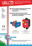
1549 I EN ISTRUZIONI PER L’USO INSTRUCTIONS FOR USE F MODE D’EMPLOI D GEBRAUCHSANWEISUNG E INSTRUCCIONES NL GEBRUIKSAANWIJZING PL INSTRUKCJA OBSŁUGI P INSTRUÇÕES DE USO HU HASZNÁLATI ÚTMUTATÓ 1549 COMPONENTI - COMPONENTS - COMPOSANTS - BESTANDTEILE COMPONENTES - ONDERDELEN - CZĘŚCI - COMPONENTES - TARTOZÉKOK VN961 96TBP VN962 VN960 2 M8x60 I ISTRUZIONI PER L’USO UTENSILE PER MONTAGGIO AMMORTIZZATORI CON TAMPONE DI FINE CORSA A MOLLA COMPONENTI Codice Beta Descrizione VN961 Supporto per tira stelo VN962 Tira stelo VN960 Morsetto universale blocca stelo M8x60 Viti TCCE 8x60 96TBP Chiave 6 mm a “L” commerciale APPLICAZIONE Marca BMW, Fiat, Ford, MB, Nissan, Peugeot, Toyota Il nuovo “TIRA STELO” è ideato per mantenere lo stelo in estensione durante il montaggio delle molle. La nuova generazione di ammortizzatori ha un cilindro idraulico-gas che rientra automaticamente una volta tolta la molla. DATI TECNICI Stelo: Ø12 mm. MIN – Ø 28 mm. MAX Materiale: Resina acetalica + alluminio (per non danneggiare lo stelo) (rif. VN960) Spessore: 20 mm (rif. VN960) SMONTAGGIO - Rimuovere completamente l’ammortizzatore Spostare verso l’alto il parapolvere o il tampone Sgrassare lo stelo del cilindro Montare e fissare il morsetto 1 2 3 4 5 6 MONTAGGIO 1. Posizionare il morsetto con le viti di fissaggio. 2. Avvitare il tira stelo nel supporto posizionando l’unità sull’ammortizzatore e fissare lo stelo del cilindro con il dado di bloccaggio. 3. Estrarre il tira stelo e bloccarlo con una leggera rota zione verso destra o sinistra. 4. Nel caso in cui i tamponi non cedono con la norma le forza muscolare, è possibile estrarre lo stelo di altri 20 mm mantenendo fermo il supporto e ruotando il tira stelo. 5. A estrazione ultimata, bloccare il morsetto con le apposite viti. 6. Lo stelo in estensione determina la posizione finale ottenuta dal corretto utilizzo del dispositivo. 3 EN INSTRUCTIONS FOR USE SPECIAL KIT FOR MOUNTING SHOCK ABSORBERS WITH SPRING “STOP BUFFER COMPONENTS Beta item number Description VN961 Support for stem puller VN962 Stem puller VN960 Stem locking universal clamp M8x60 TCCE 8x60 screws 96TBP Commercial 6 mm “L” key APPLICATION Brand BMW, Fiat, Ford, MB, Nissan, Peugeot, Toyota The new “ROD-STOPPER ” is suitable for holding the shock-absorber rod, when mounting & dismounting the coils. In fact the new generation of shock-absorbers has an Hydraulic-Gas cylinder that is retracting automatically when is free from the coil. TECHNICAL DATA Rod Range: Ø12 mm. MIN – Ø 28 mm. MAX Material: Aluminum (for not damaging the Rod). (Ref. VN960) Thickness: 20 mm (Ref. VN960) DISMOUNTING - Completely remove the shock absorber Move the dust protector or the buffer Degrease the cylinder stem Mount and fix the clamp 1 2 3 4 5 6 MOUNTING 1. Position the clamp with the fixing screws. 2. Screw the stem puller in the support by positioning the unit on the shock absorber and fix the stem of the cylinder with the locking nut. 3. E xtract the stem puller and lock it with a light rotation towards right or left. 4. I n case the buffers do not relent with normal muscular force, it is possible to extract the stem by another 20 mm by keeping the support still and rotating the stem puller. 5. W hen the extraction is complete, lock the clamp with the appropriate screws. 6. The stem in extension determines the final position obtained by correct use of the device. 4 F MODE D’EMPLOI OUTIL POUR LE MONTAGE DES AMORTISSEURS AVEC TAMPONS DE BUTEE D’ARRET A RESSORT COMPOSANTS Beta code Description VN961 Suport pour l’exctracteur du tige VN962 exctracteur du tige VN960 Borne universel pour le blocage du tige M8x60 Vis TCCE 8x60 96TBP Clé comercialle 6 mm à “L” APPLICATION Marque BMW, Fiat, Ford, MB, Nissan, Peugeot, Toyota Le nouveau bloqueur de tige est conçu pour soutenir la tige d’amortisseur, lors du montage et du démontage des rouleaux. En fait, la nouvelle génération de tiges d’amortisseurs possède un vérin hydraulique- gaz qui se rétracte automatiquement et qui n’a pas de rouleau. DONES TECHNIQUES Gamme de tiges: Ø12 mm. MIN – Ø 28 mm. MAX Matériel: Aluminium (pour ne pas endommager la tige) (Réf. VN960) Epaisseur: 20 mm (Réf. VN960) DEMONTAGE - Retirer complètement les amortisseurs Placer l’anti-poussière ou le tampon vers le haut Dégraisser la tige du cylindre Monter et fixer la borne 1 2 3 4 5 6 MONTAGE 1. Positionner la borne avec les vis de fixation. 2. Visser le tire-tige sur le support positionnant l’unité sur l’amortisseur et fixer la tige du cylindre avec l’écrou de verrouillage. 3. E xtraire la tige et la bloquer avec une légère rotation vers la droite ou vers la gauche. 4. Si les tampons ne cèdent pas avec une force musculaire normale, il est possible d’extraire la tige à une hauteur de 20mm tout en maintenant ferme ment le support et en faisant tourner le tire-tige. 5. Une fois l’extraction achevée, bloquer la borne avec les vis spéciales. 6. La tige en extension détermine la position finale ob tenue par la bonne utilisation du dispositif. 5 D GEBRAUCHSANWEISUNG WERKZEUG ZUR MONTAGE VON STOSSDÄMPFERN MIT FEDERBEINANSCHLAGPUFFER BESTANDTEILE Beta Code Beschreibung VN961 Unterstützung für Kolbenstange-Abzieher VN962 Kolbenstange-Abzieher VN960 Universelle Klemme für Kolbenstange-Abzieher M8x60 Schraube TCCE 8x60 96TBP Kommerzieller “L” Schlüssel 6 mm ANWENDUNG Marke BMW, Fiat, Ford, MB, Nissan, Peugeot, Toyota Die neue “ROD-STOPPER” ist eine Stütze des Stoβdämpfers während des Ein- und Ausbaus der Spulen. Die neue Generation von Stoβdämpfern besitzt einen Hydraulik-Gas-Zylinder, der sich automatisch zurückzieht, wenn er von der Spule getrennt ist. TECHNISCHE DATEN Durchmesser der Stange: Ø12 mm. MIN – Ø 28 mm. MAX Material: Aluminium (um die Stange nicht zu beschädigen) (Bez. VN960) Stärke: 20 mm (Bez. VN960) AUSBAU - Den Stoβdämpfer vollständig entfernen - Den Staubschutz oder Anschlagpuffer nach ober hin versetzen - Die Zylinderkolbenstange entfetten - Die Klemme montieren und befestigen 1 2 3 5 6 MONTAGE 1. Die Klemme mit den Befestigungsschrauben positio nieren. 2. Den Stangenspanner in die Halterung schrauben, die Einheit auf dem Stoβdämpfer positionieren und die Zylinderkolbenstange mit der Befestigungsmutter fi xieren. 3. Den Stangenspanner herausziehen und durch eine 4 leicht Drehung nach rechts oder links blockieren. 4. Wenn sich die Anschlagpuffer nicht durch die normale Muskekraft lösen lassen, kann die Zylinderkolbenstan ge um weitere 20 mm herausgezogen werden, wobei die Halterungfestgehalten und der Stangenspanner gedreht werden muss. 5. Nach erfolgter Entnahme die Klemme mit den entspre chenden Schrauben blockieren. 6. Die ausgezogene Zylinderkolbenstange bestimnmt die endgültige Position, die durch die korrekte Verwen dung der Vorrichtung erreicht wird. 6 E INSTRUCCIONES HERRAMIENTA PARA EL MONTAJE DE LOS AMORTIZADORES CON TAMPÓN DE TOPE A MUELE COMPONENTES Código Beta Descripción VN961 Soporte para el extractor de la barra VN962 Extractor de la barra VN960 Prensa universal para el extractor de la barra M8x60 Tornillo TCCE 8x60 96TBP Llave comercial 6 mm a “L” APLICACIÓN Marca BMW, Fiat, Ford, MB, Nissan, Peugeot, Toyota El nuevo “ROD-STOPPER ” es adecuado para sujetar la barra del amortiguador cuando se montan y se desmontan las bobinas. De hecho, la nueva generación de amortiguadores tiene un cilindro Hidráulico-Gas que se retrae automáticamente cuando se libera de la bobina. DATOS TÉCNICOS Diámetro Barra: Ø12 mm. MÍN – Ø 28 mm. MÁX Material: Aluminio (para no dañar la Barra) (ref. VN960 ) Espesor: 20 mm (ref. VN960 ) DESMONTAJE - Retire completamente el amortiguador Levante el suplemento antipolvo o el tampón Engrase el vástago del cilindro Monte y fije la mordaza 1 2 3 4 5 6 MONTAJE 1. Coloque la mordaza con los tornillos de fjación. 2. Atornille el vástago colocando la unidad sobre el amortiguador y fije el vástago del cilindro con la tuerca de bloqueo. 3. Extraiga el tirador del vástago y bloqueelo con una ligera rotación hacia la derecha o la izquierda. 4. Si los tampones no ceden con la normal fuerza muscular, es posible extraer el vástago otros 20 mm más, manteniendo inmóvil el soporte y rotando el tirador del vástago. 5. Cuando termine la extracción, bloquee la mordaza con los tornillos. 6. El vástago en extensión determina la posición final obtenida con el uso correcto del dispositivo. 7 NL GEBRUIKSAANWIJZING GEREEDSCHAP VOOR DE MONTAGE VAN SCHOKDEMPERS MET AANSLAGBUFFER MET VEER ONDERDELEN Beta code Beschrijving VN961 Steun voor de trekstang VN962 Trekstang VN960 Universele borgklem stang M8x60 Inbusschroeven 8x60 96TBP Commerciële L-sleutel 6 mm TOEPASSING Merk BMW, Fiat, Ford, MB, Nissan, Peugeot, Toyota De nieuwe “TREKSTANG” is ontwikkeld om de stang uitgetrokken te houden tijdens de montage van de veren. De nieuwe generatie schokdempers heeft een gasgevulde hydraulische cilinder, die automatisch ingetrokken wordt zodra de veer verwijderd is TECHNISCHE GEGEVENS Stang: Ø12 mm. MIN – Ø 28 mm. MAX Materiaal: Polyacetaal + aluminium (om de stang niet te beschadigen) (ref. VN960) Dikte: 20 mm (ref. VN960) DEMONTAGE - Verwijder de schokdemper volledig - Verplaats de stofkap of de buffer omhoog - Smeer de cilinderstang - Monteer de klem en zet hem vast 1 2 3 4 5 6 MONTAGE 1. Breng de klem met de bevestigingsschroeven aan. 2. Schroef de trekstang in de steun en zet de unit op de schokdemper. Zet de cilinderstang met de borg moer vast. 3. Trek de trekstang uit en zet hem met een lichte dra aiing naar rechts of links vast. 4. Indien de buffers niet met de normale spierkracht zwichten, kan de stang nog 20 mm worden uitgetrok ken, terwijl u de steun vasthoudt en de trekstang draait. 5. Nadat de stang is uitgetrokken, zet u de klem met de hiervoor bestemde schroeven vast. 6. De uitgetrokken stang bepaalt de door het juiste ge bruik van het apparaat bereikte eindpositie. 8 PL INSTRUKCJA OBSŁUGI NARZĘDZIE DO INSTALACJI AMORTYZATORÓW Z ODBOJEM WYŁĄCZNIKA NA SPRĘŻYNĘ KOMPONENTY Kod Beta Opis VN961 Podstawa cięgna VN962 Cięgno VN960 Uniwersalny zacisk blokady trzpienia M8x60 Śruby TCCE 8x60 96TBP Klucz 6 mm typu „L” komercyjny ZASTOSOWANIE Marka BMW, Fiat, Ford, MB, Nissan, Peugeot, Toyota Nowe „CIĘGNO” przeznaczone jest do utrzymania trzpienia w rozszerzeniu podczas montażu sprężyn. Nowa generacja amortyzatorów ma siłownik hydrauliczny-gazowy, który automatycznie chowa się po usunięciu sprężyny. DANE TECHNICZNE Trzpień: MIN Ø12 mm – MAX Ø 28 mm Materiał: Żywica acetalowa + aluminium (aby nie uszkodzić trzpienia) (ref. VN960) Grubość: 20 mm (ref. VN960) DEMONTAŻ - Wyjąć całkowicie amortyzator - Przesunąć w górę osłonę lub odbój - Odtłuścić trzpień cylindra - Założyć i przymocować zacisk 1 2 3 4 5 6 MONTAŻ 1. Ustawić zacisk ze śrubami mocującymi. 2. Przykręcić cięgno w podstawie ustawiając całość na amortyzatorze i przymocować trzpień cylindra nakrętkę blokującą. 3. Wyciągnąć cięgno i zablokować je obracając delikat nie w prawo lub w lewo. 4. W przypadku, gdy odboje nie ustępują przy użyciu normalnej siły mięśni, można wyciągnąć trzpień do datkowo na 20 mm trzymając nieruchomo podstawę i obracając cięgno. 5. Po całkowitym wyciągnięciu, zablokować zacisk za pomocą odpowiednich śrub. 6. Rozszerzenie trzpienia określa ostateczną pozycję uzyskaną przez właściwe zastosowanie urządzenia. 9 P INSTRUÇÕES DE USO FERRAMENTA PARA MONTAR AMORTECEDORES COM TAMPÃO DE FIM DE CURSO COM MOLA COMPONENTES Código Beta Descrição VN961 Suporte para extensor de haste VN962 Extensor de haste VN960 Borne universal bloqueador de haste M8x60 Parafusos Cabeça Cilíndrica Hexagonal 8x60 96TBP Chave 6 mm “L” comercial APLICAÇÃO Marca BMW, Fiat, Ford, MB, Nissan, Peugeot, Toyota O novo “EXTENSOR DE HASTE” é projetado para manter a haste estendida durante a montagem das molas. A nova geração de amortecedores tem um cilindro hidráulico-gás que recua automaticamente depois da remoção da mola. DADOS TÉCNICOS Haste: Ø12 mm. MIN – Ø 28 mm. MAX Material: Resina acetálica + alumínio (para não danificar a haste) (ref. VN960) Espessura: 20 mm (ref. VN960) DESMONTAGEM - Remover totalmente o amortecedor - Deslocar para cima o vedador de poeira ou o tampão - Desengraxar a haste do cilindro - Montar e fixar o borne 1 2 3 4 5 6 MONTAGEM 1. Posicionar o borne com os parafusos de fixação. 2. Aparafusar o extensor de haste no suporte posicio nando a unidade no amortecedor e fixar a haste do cilindro com a porca de bloqueio. 3. Extrair o extensor de haste e bloqueá-lo com uma ligeira rotação para a direita ou para a esquerda. 4. Se os tampões não cedem com a força muscular normal, é possível extrair a haste de mais 20 mm mantendo o suporte firme e virando o extensor de haste. 5. Finalizada a extração, bloquear o borne com os parafusos apropriados. 6. A haste estendida estabelece a posição final obtida pela utilização correta do dispositivo. 10 HU HASZNÁLATI ÚTMUTATÓ SZERSZÁM ZÁRÓ TAMPONOS JÁRATVÉGI RUGÓS LÖKÉSHÁRÍTÓVAL ELLÁTOTT LENGÉSCSILLAPÍTÓK FELSZERELÉSÉHEZ KOMPONENSEK Beta Kód Leírás VN961 Húzókat támaszték VN962 Húzókar VN960 Húzókart rögzítő univerzális szorítókapocs M8x60 TCCE 8x60 csavarok 96TBP 6 mm-es kommersz “L” kulcs FELHASZNÁLÁS Márka BMW, Fiat, Ford, MB, Nissan, Peugeot, Toyota Az új típusú “HÚZÓKAR” arra lett kifejlesztve, hogy a rugók felszerelése alatt feszítve tartsa a kart. A lengéscsillapítók legújabb generációját hidraulikus-gáz hengerrel látják el, amely a rugók eltávolításakor automatikusan visszahúzódnak. TECHNIKAI ADATOK Húzókar: Ø12 mm. MIN – Ø 28 mm. MAX Anyaga: műviasz + alumínium (a húzókar védelmére) (rif. VN960) Vastagság: 20 mm (rif. VN960) LESZERELÉS - Távolítsuk el teljesen a lengéscsillapítót - Emeljük fel a porfogót illetve a lökéshárító záró tampont - Zsírozzuk be a henger húzókarját - Szereljük fel és rögzítsük a szorítókapcsot 1 2 3 4 5 6 FELSZERELÉS 1. Rögzítsük a szorítókapcsot a rögzítő csavarokkal 2. Csavarozzuk a húzókart a helyére és helyezzük az egységet a lengéscsillapítóra, majd a rögzítő csapo kkal rögzítsük a henger húzókarját 3. Távolítsuk el a húzókart és jobbra vagy balra forga tva rögzítsük azt 4. Ha a záró tamponokat nem tudjuk puszta kézzel el távolítani, a támaszték mozgatása nélkül a húzókar még elmozdítható 20 mm-rel. 5. Az eltávolítás elvégzése után, rögzítsük a szorítókapcsot a megfelelő csavarokkal. 6. A húzókar megfeszítése befolyásolja a végleges pozíciót, amely a szerkezet helyes működéséből ered. 11 BETA UTENSILI S.p.A. via Alessandro Volta, 18 - 20845 Sovico (MB) ITALY Tel. +39 039.2077.1 - Fax +39 039.2010742 www.beta-tools.com - [email protected]