1
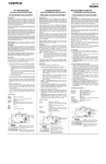
TEMPORIZZATORE ELETTROMECCANICO PER SBRINAMENTO: serie SB3
I
CARATTERISTICHE E ISTRUZIONI PER L'USO
• TENSIONE DI ALIMENTAZIONE:
Vedi dati di targa dell'apparecchio.
Disponibilità: 24 V - 115 V - 230 V (+10% -15%) a 50 o 60 Hz
• TEMPERATURA DI FUNZIONAMENTO:
Max 55°C
• VALORE NOMINALE DEI CONTATTI:
16(6)A - 250 Vac
• CONNESSIONI ELETTRICHE:
Max 8 terminali FASTON 6,3 mm x 0,8 mm
• TIPO DI AZIONE E CARATTERISTICHE COMPLEMENTARI:
Tipo 1.B
• MONTAGGIO SPORGENTE:
Tramite 2 viti Ø 4 mm. Vedi fig. 1
• MONTAGGIO SU PROFILATO DIN (DIN/EN 50022):
Due possibilità di montaggio tramite adattatore a richiesta. Vedi fig. 2
• SITUAZIONE DI POLLUZIONE:
Normale.
• APPROVAZIONI:
ENEC 03
• PROTEZIONE CONNESSIONI ELETTRICHE:
La protezione, fornita non montata, deve essere applicata e bloccata
con l'apposita vite dopo aver eseguito il cablaggio.
NB: le aperture per il passaggio dei cavi possono essere ampliate
asportando il settore centrale preinciso.
• TEMPORIZZAZIONE:
La fig. 3 mostra i diagrammi ed i relativi tempi di commutazione:
T1 e T2 regolabili (T1+T2 = 60 min. max), T3 fisso (solo mod. SB3.92).
Nel mod. SB3.72 i due contatti commutano simultaneamente (solo T1).
Possibilità di selezionare da 1 a 12 commutazioni al giorno.
• APPLICAZIONI TIPICHE:
Vedi fig. 4.1: Sbrinamento a gas caldo (inversione di ciclo).
Vedi fig. 4.2: Sbrinamento a resistenza con ritardo avviamento ventola.
Vedi fig. 4.3: Sbrinamento semplice a resistenza.
Vedi fig. 4.4: Sbrinamento ottimale tramite termostato di fine sbrinamento, con tempo di sicurezza (T1) in caso di guasto del termostato.
NB: la fig. 4 mostra gli schemi elettrici applicati ai modelli disponibili.
C = raffreddamento T = termostato raffreddamento
D = sbrinamento V = valvola inversione ciclo R = relè
F = ventilazione TD = termostato di fine sbrinamento
• REGOLAZIONE:
Vedi fig. 5. Impostare il tempo di sbrinamento T1 portando l'indice (A)
sul valore desiderato della scala (B). Impostare il tempo di ritardo
ventola T2 portando l'indice (C) sul valore desiderato della scala (D).
Impostare il numero degli sbrinamenti desiderati nelle 24 ore
abbassando uno o più tasselli (E) del quadrante delle ore (F).
• MESSA ALL'ORA:
Vedi fig. 5. Ruotare in senso orario la manopola (G) fino a far coincidere
la punta dell'azionatore (H) con l'ora d’inizio funzionamento letta sul
quadrante delle ore (F).
Nota 1: L'inizio dello sbrinamento avviene circa all'ora dispari di ciascun
tassello (E) abbassato.
Nota 2: Ad ogni giro della manopola (G) corrisponde uno spostamento
di 2 ore del quadrante (F).
• ESEMPIO:
Si desiderano 3 sbrinamenti al giorno, alle ore 7, alle ore 15 ed alle ore
23, della durata di 30 min. più 5 min. di ritardo avviamento ventola.
L'inizio funzionamento avviene alle ore 2.
1°) Posizionare l'indice (A) sul valore 30 della scala (B).
2°) Posizionare l'indice (C) sul valore 5 della scala (D).
3°) Abbassare i tasselli (E) corrispondenti alle ore 6-8, 14-16, 22-24.
4°) Ruotare la manopola (G) per allineare le ore 2 del quadrante (F)
con la punta dell'azionatore (H).
GARANZIA: questi apparecchi sono garantiti per 12 mesi contro difetti dovuti ai materiali o alla lavorazione purché applicati ed usati propriamente.
Questa garanzia copre riparazioni o sostituzioni franco nostra officina senza dar diritto alla richiesta di risarcimento per danni o spese.
ELECTROMECHANICAL TIME SWITCHES FOR DEFROSTING: series SB3
GB
OPERATING INSTRUCTIONS
• SUPPLY VOLTAGES:
See ratings on the timer label.
Availability: 24 V - 115 V - 230 V (+10% -15%) at 50 or 60 Hz
• OPERATING TEMPERATURE:
Max 55°C
• CONTACT RATING:
16(6) A - 250 Vac
• ACTION TYPE AND COMPLEMENTARY FEATURES:
Type 1.B
• ELECTRICAL CONNECTIONS:
Max 8 FASTON terminals 6,3 mm x 0,8 mm
• REAR MOUNTING:
With 2 screws Ø 4 mm. See fig. 1
• DIN RAIL MOUNTING (DIN/EN 50022):
Two possibilities by means of an adaptor (on request). See fig. 2
• POLLUTION SITUATION:
Normal
• APPROVALS:
ENEC 03
• ELECTRICAL CONNECTION PROTECTION:
The cover, supplied not fastened, must be positioned and fastened with
the screw after wiring.
NB: The slots for the passage of the wires can be widened removing
the pre-cut central sector.
• TIMING:
See fig. 3 - switching intervals:
T1 and T2 adjustables (T1+T2 = 60 mins max)
T3 fixed (only type SB3.92).
Type SB3.72: the two contacts switch simultaneously.
From 1 to 12 defrosts per day.
• TYPICAL APPLICATIONS:
See fig. 4.1: Defrosting with hot gas.
See fig. 4.2: Defrosting with fan delay.
See fig. 4.3: Defrosting with resistor.
See fig. 4.4: Defrost termination by thermostat with safety reset if
thermostat fails.
Wiring: See fig. 4
C = cooling
T = cooling thermostat
D = defrosting
R = relay
V = reverse cycle valve F = fan TD = defrost termination thermostat
• PROGRAMME SETTING:
See fig. 5. Set defrost period T1 by aligning pointer (A) to number of
wanted minutes of graduation (B). Set delay period T2 (only SB3.82) by
aligning pointer (C) to number of wanted minutes of graduation (D).
Set number of defrosts per day by pushing down one or more trips (E).
• TIME SETTING:
See fig. 5. Turn knob (G) clockwise until tip of actuator (H) aligns with
the actual time on the hour dial (F).
Note 1: The unit switches on around the odd hour of each lowered trip.
Note 2: Each revolution of knob (G) rotates dial (F) 2 hours.
• EXAMPLE:
T1 = 30 mins - T2 = 5 mins - Three defrosts per day at 7.00 hrs, at
15.00 hrs and 21.00 hrs - Actual time = 2.00 hrs.
1°) Pointer (A) on nick 30 of graduation (B).
2°) Pointer (C) on nick 5 of graduation (D).
3°) Trips (E) 6-8, 14-16, 22-24 pushed down.
4°) Nick 2 of the dial (F) aligned with tip of actuator (H).
GUARANTEE: These units are guaranteed for 12 months against
material or manufacturing defects, provided their application and use
are correct. This guarantee covers repairs or replacements free our
works without the right, however, of a claim for compensation for
damages or expenses.
BIGATTI temporizzatori
S.r.l. via Redipuglia, 16 - 20010 Bareggio (MI) - ITALY
tel. +39 02 90362613 fax +39 02 9013203