1
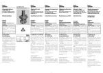
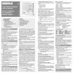
FALCON M
Istruzioni per l’uso - Instructions for use - Instructions pour l’usager
- Instrucciones para el uso - Gebrauchsanleitung - Gids voor de
gebruiker
Fig. 2
Fig. 1
ITALIANO
Leggere attentamente le istruzioni prima di utilizzare il prodotto e
conservarle per eventuali necessità future
Tipo di pignone
Velocità del cancello
(m/min.)
Lunghezza max. cancello
(m)
Tipo di finecorsa
NORME GENERALI DI SICUREZZA
L’automazione FALCON M, se correttamente installata ed utilizzata,
garantisce un elevato grado di sicurezza. Alcune semplici norme
di comportamento possono evitare inoltre inconvenienti accidentali:
- Non sostare e non permettere a bambini, persone o cose di sostare nelle vicinanze dell’automazione, sopprattutto durante il funzionamento.
- Tenere fuori dalla portata dei bambini, radiocomandi o qualsiasi altro
datore d’impulso che possa azionare involontariamente l’automazione.
- Non permettere ai bambini di giocare con l’automazione.
- Non contrastare volontariamente il movimento del cancello.
- Evitare che rami o arbusti possano interferire col movimento del cancello.
- Mantenere efficienti e ben visibili i sistemi di segnalazione luminosa.
- Non tentare di azionare manualmente il cancello se non dopo averlo
sbloccato.
- In caso di malfunzionamenti, sbloccare il cancello per consentire l’accesso ed attendere l’intervento tecnico di personale qualificato.
- Una volta predisposto il funzionamento manuale, prima di ripristinare il
funzionamento normale, togliere alimentazione elettrica all’impianto.
- Non eseguire alcuna modifica sui componenti facenti parte il sistema
d’automazione.
- Astenersi da qualsiasi tentativo di riparazione o d’intervento diretto e
rivolgersi solo a personale qualificato.
- Far verificare almeno semestralmente l’efficienza dell’automazione,
dei dispositivi di sicurezza e del collegamento di terra da personale
qualificato.
•
•
•
•
•
•
•
•
•
12
Frequenza d’utilizzo (vedi
grafico)
Temperatura ambiente (°C)
Peso del motoriduttore (Kg)
8M
8 MC
Z 16 modulo 4
14
12
14
424 M
424 MC
12
15
Magnetico
Controllo di coppia elettronico
(Vedi centrale)
Tipo di frizione
S3 - 30%
9
(10 Falcon
5MC)
Grado di protezione
Dimensioni operatore
S3 - 40%
-20 ÷ +55
10
(11 Falcon
8MC)
IP 44
Vedi fig. 2
100%
7.5
(8.5 Falcon
424MC)
FUNZIONAMENTO MANUALE
Lo sblocco manuale è un dispositivo che permette di svincolare
l’operatore dal cancello permettendone la movimentazione
manuale.
Prima di agire sul dispositivo di sblocco togliere tensione all’impianto agendo sull’interruttore differenziale a monte del motoriduttore.
IL DISPOSITIVO DI SBLOCCO NON SI DEVE CONSIDERARE UN ARRESTO
D’EMERGENZA
Nel caso sia necessario azionare manualmente il cancello a causa di
mancanza di alimentazione elettrica o disservizio dell’automazione, è
necessario agire sul dispositivo di sblocco come segue:
1. Inserire l’apposita chiave in dotazione nella serratura, Fig. 1 Rif. a, e
ruotarla in senso orario come indicato in Fig. 1 Rif. b.
2. Ruotare il sistema di sblocco in senso orario di circa 180°, come indicato in Fig. 1 Rif. c.
3. Effettuare manualmente la manovra di apertura o chiusura.
DESCRIZIONE
•
5M
5 MC
MODELLO
L’automazione FALCON M è ideale per il controllo di aree di accesso
veicolare in ambito residenziale.
FALCON M per cancelli scorrevoli è un operatore elettromeccanico
che trasmette il movimento all’anta tramite un pignone a cremagliera.
Per il dettagliato comportamento del cancello scorrevole nelle diverse
logiche di funzionamento, fare riferimento al Tecnico d’installazione.
Nelle automazioni sono presenti dispositivi di rilevazione ostacolo
(fotocellule) che impediscono la richiusura del cancello quando un
ostacolo si trova nella zona da loro protetta.
Il sistema garantisce il blocco meccanico quando il motore non è in
funzione e quindi non occorre installare alcuna serratura.
L’apertura manuale è quindi possibile solo intervenendo sull’apposito
sistema di sblocco.
Il motoriduttore è dotato di frizione elettronica regolabile che permette
un uso sicuro dell’automazione.
L’apparecchiatura elettronica è incorporata nel motoriduttore.
Un comodo sblocco manuale rende manovrabile il cancello in caso di
black-out o disservizio.
La segnalazione luminosa indica il movimento in atto del cancello.
RIPRISTINO DEL FUNZIONAMENTO NORMALE
Per evitare che un impulso involontario possa azionare il cancello
durante la manovra , prima di ribloccare l’operatore, togliere
alimentazione all’impianto.
1. Ruotare il sistema di sblocco in senso antiorario di circa 180°, come
indicato in Fig. 2 rif. a.
2. Ruotare la chiave in senso antiorario, Fig. 2 rif. b, ed estrarla dalla serratura, come indicato in Fig. 2 rif. c.
3. Muovere il cancello fino all’ingranamento dello sblocco.
Prima di ripristinare l’alimentazione al sistema verificare che il cancello non si possa muovere manualmente.
MANUTENZIONE
Al fine d’assicurare nel tempo un corretto funzionamento ed un costante
livello di sicurezza è opportuno eseguire, con cadenza semestrale, un
controllo generale dell’impianto. Nel fascicolo “Istruzioni per l’uso” è stato
predisposto un modulo per la registrazione degli interventi di manutenzione.
CARATTERISTICHE TECNICHE
5M
8M
424 M
5 MC
8 MC
424 MC
230 V~ 115 V~ 230 V~ 115 V~ 230 V~ 115 V~
Alimentazione (+6% -10%)
50 Hz 60 Hz 50 Hz 60 Hz 50 Hz 60 Hz
Potenza assorbita (W)
350
500
600
70
Corrente assorbita (A)
1.5
3
2.2
5.2
3
Condensatore di spunto (µF)
10
30
12.5
50
/
Spinta sul pignone (daN)
45
65
40
Coppia (Nm)
18
24
13.5
Termoprotezione (°C)
140
/
Peso anta max. (Kg)
500
800
400
MODELLO
Il modulo per la manutenzione allegato ha uno scopo puramente
indicativo, non è escluso che per garantire il corretto funzionamento dell’automazione ed un costante livello di sicurezza siano
necessarie operazioni di manutenzione non riportate nel modulo.
RIPARAZIONI
L’utente utilizzatore deve astenersi da qualsiasi tentativo di riparazione o
d’intervento e deve rivolgersi solo ed esclusivamente a personale qualificato GENIUS o centri d’assistenza GENIUS.
1
ENGLISH
Read the instructions carefully before using the product and store
them for future use
5M
5 MC
MODEL
Gate speed (m/min)
Max. gate length (m)
Type of travel-limit device
GENERAL SAFETY REGULATIONS
If correctly installed and used, the FALCON M automated system
will ensure a high degree of safety. Some simple rules on behaviour can prevent accidental trouble:
Type of clutch
- Do not stand near the automatic system, and do not allow children,
persons or things to do so, especially when it is operating.
- Keep radio-controls, or any other pulse generators that could involuntarily activate the automated system, well away from children.
- Do not allow children to play with the automated system.
- Do not willingly obstruct gate movement.
- Prevent any branches or shrubs from interfering with gate movement.
- Keep the indicator-lights efficient and easy to see.
- Do not attempt to activate the gate by hand unless you have released
it.
- In the event of malfunctions, release the gate to allow access and wait
for qualified technical personnel to do the necessary work.
- When you have set manual operation mode, cut power to the system
before restoring normal operation.
- Do not in any way modify the components of the automated system.
- Do not attempt any kind of repair or direct action whatever and contact qualified personnel only.
- At least every six months: arrange a check by qualified personnel of the
automatic system, safety devices and earth connection.
Use frequency (see graph)
Operating ambient temperature (°C)
Weight of gearmotor (Kg)
12
8M
8 MC
14
12
424 M
424 MC
12
14
15
Magnetic
Electronic torque control
(See control unit)
S3 - 30%
S3 - 40%
100%
-20 ÷ +55
9
(10 Falcon
5MC)
Protection class
Operator dimensions
10
(11 Falcon
8MC)
IP 44
See fig. 2
7.5
(8.5 Falcon
424MC)
MANUAL OPERATION
The manual release is a device that makes it possible to disconnect
the operator from the gate, thus enabling manual movement.
Before using the release device, cut power to the system, with the
differential switch upstream of the gearmotor.
THE RELEASE DEVICE MUST NOT BE CONSIDERED AN EMERGENCY STOP
If the gate has to be moved manually due to a power cut or fault of the
automated system, use the release device as follows:
1. Fit the supplied key in the lock, Fig. 1 Ref. a, and turn it clockwise as
shown in Fig. 1 Ref. b.
2. Turn the release system clockwise by about 180°, as shown in Fig. 1 Ref.
c.
3. Open and close the gate manually.
DESCRIPTION
The FALCON M automated system is ideal for controlling vehicle access
areas in residential environments.
FALCON M for sliding gates is an electro-mechanical operator which
transmits motion to the leaf via a rack and pinion.
For details on sliding gate behaviour in different function logics, consult
the installation Technician.
Automated systems include obstacle detection devices (photocells) that
prevent the gate from closing when there is an obstacle in the area
they protect.
The system ensures mechanical locking when the motor is not operating
and, therefore, installing a lock is unnecessary.
Manual opening is, therefore, only possible by using the release system.
The gearmotor has an adjustable electronic clutch enabling safe use of
the automated system.
The control unit is built into the gearmotor.
A handy manual release facility makes it possible to move the gate in the
event of a power cut or fault.
The warning-light indicates that the gate is currently moving.
RESTORING NORMAL OPERATION MODE
To prevent an involuntary pulse from activating the gate during
the manoeuvre, cut power to the system before re-locking the
operator.
1. Turn the release system anti-clockwise by about 180°, as shown in Fig.
2 ref. a.
2. Turn the key anti-clockwise, Fig. 2 ref. b, and remove it from the lock, as
shown in Fig. 2 ref. c.
3. Move the gate until it meshes to release.
Before powering up the system again, make sure that the gate cannot be moved manually.
MAINTENANCE
TECHNICAL SPECIFICATIONS
To ensure correct long-term operation and a constant level of safety, we
advise you to generally control the system every 6 months. In the “Use
Instructions” booklet, there is a form for recording maintenance jobs.
5M
8M
424 M
5 MC
8 MC
424 MC
230 V~ 115 V~ 230 V~ 115 V~ 230 V~ 115 V~
Power supply (+6% -10%)
50 Hz 60 Hz 50 Hz 60 Hz 50 Hz 60 Hz
Absorbed power (W)
350
500
600
70
Absorbed current (A)
1.5
3
2.2
5.2
3
Thrust capacitor (µF)
10
30
12.5
50
/
Thrust on pinion (daN)
45
65
40
Torque (Nm)
18
24
13.5
Temperature protection (°C)
140
/
Max leaf weight (Kg)
500
800
400
Type of pinion gear
Z 16 module 4
MODEL
The enclosed maintenance form is purely a guideline; it cannot be
ruled out that to guarantee a correctly operating automated system and a constant level of safety, maintenance operations not
described in this form may be necessary.
REPAIRS
The User must not in any way attempt to repair or to take direct action
and must solely contact qualified GENIUS personnel or GENIUS service
centres.
FRANÇAIS
-
-
Lire attentivement les instructions avant d’utiliser le produit et les
conserver pour toute nécessité future éventuelle
PRESCRIPTIONS GÉNÉRALES DE SÉCURITÉ
-
S’il est correctement installé et utilisé, l’automatisme FALCON M
garantit un haut niveau de sécurité. Par ailleurs, quelques règles
simples de comportement peuvent éviter bien des accidents
-
- Ne pas stationner et interdire aux enfants, aux personnes et aux choses
de stationner près de l’automatisme et en particulier durant le
fonctionnement.
- Éloigner de la portée des enfants les radiocommandes ou tout autre
dispositif générateur d’impulsion, pour éviter que l’automatisme ne
soit actionné involontairement.
- Interdire aux enfants de jouer avec l’automatisme.
- Ne pas contraster volontairement le mouvement du portail.
- Éviter que des branches ou des arbustes n’entravent le mouvement
du
portail.
- Faire en sorte que les systèmes de signalisation lumineuse soient
toujours
efficients et bien visibles.
-
-
N’actionner manuellement le portail qu’après l’avoir déverrouillé.
En cas de dysfonctionnement, déverrouiller le portail pour permettre
l’accès et attendre l’intervention technique du personnel qualifié.
Lorsque le fonctionnement manuel a été disposé, couper le courant
sur
l’installation avant de rétablir le fonctionnement normal.
N’effectuer aucune modification sur les composants qui font partie
du
système d’automation.
Éviter toute tentative de réparation ou d’intervention directe et
s’adresser
uniquement à du personnel qualifié.
Faire vérifier, au moins tous les six mois, l’efficience de l’automatisme,
des
dispositifs de sécurité et de la mise à la terre par du personnel qualifié.
DESCRIPTION
•
•
L’automatisme FALCON M est l’idéal pour le contrôle des zones d’accès de véhicules dans un cadre domestique.
FALCON M pour portails coulissants est un opérateur électromécanique
qui transmet le mouvement au vantail par l’intermédiaire d’un pignon
à crémaillère.
•
•
•
•
•
•
•
•
FONCTIONNEMENT MANUEL
Pour le comportement détaillé du portail coulissant dans les différentes
logiques de fonctionnement, s’adresser à l’Installateur.
Les automatismes disposent de dispositifs de détection d’obstacle
(photocellules) qui empêchent la refermeture du portail en cas
d’obstacle dans la zone qu’ils protègent.
Le système garantit le blocage mécanique quand le moteur n’est pas
en fonction; il n’est donc pas nécessaire d’installer de serrure.
L’ouverture manuelle n’est donc possible qu’en intervenant sur le système de déverrouillage spécifique.
Le motoréducteur est muni d’un embrayage électronique réglable qui
permet un usage sûr de l’automatisme.
L’armoire électronique est incorporée au motoréducteur.
Un dispositif pratique de déverrouillage permet de manœuvrer le portail en cas de coupure de courant ou de dysfonctionnement.
La signalisation lumineuse indique que le portail est en mouvement.
Le déverrouillage manuel est un dispositif qui permet de dégager
l’opérateur du portail en en permettant l’actionnement manuel.
Alimentation (+6% -10%)
Puissance absorbée (W)
Courant absorbé (A)
Condensateur de démarrage (µF)
Poussée sur le pignon (daN)
Couple (Nm)
Protection thermique (°C)
Poids maxi vantail (kg)
Type de pignon
Vitesse du portail (m/min)
Longueur maxi portail (m)
Type de fin de course
Type d’embrayage
Fréquence d’utilisation (voir
graphique)
Température de fonctionnement (°C)
Poids du motoréducteur (kg)
5M
8M
424 M
5 MC
8 MC
424 MC
230 V~ 115 V~ 230 V~ 115 V~ 230 V~ 115 V~
50 Hz 60 Hz 50 Hz 60 Hz 50 Hz 60 Hz
350
500
600
70
1.5
3
2.2
5.2
3
10
30
12.5
45
18
50
65
24
140
500
RÉTABLISSEMENT DU FONCTIONNEMET NORMAL
Pour éviter qu’une impulsion involontaire n’actionne le portail
durant la manœuvre, couper le courant sur l’installation avant de
bloquer de nouveau l’opérateur.
1. Tourner le système de déverrouillage en sens inverse horaire d’environ
180°, d’après la Fig. 2 réf. a.
2. Tourner la clé en sens inverse horaire d’après la Fig. 2 réf. b, et l’extraire
de la serrure d’après la Fig. 2 réf. c.
3. Actionner le portail jusqu’à l’engrènement du déverrouillage.
/
40
13.5
/
400
Avant de remettre le système sous tension, vérifier que le portail ne
peut pas être actionné manuellement.
800
Z16 module 4
12
14
12
14
12
15
Magnétique
Contrôle électronique du couple
(Voir centrale)
S3 - 30%
S3 - 40%
LE DISPOSITF DE DÉVERROUILLAGE N’EST PAS UN ARRÊT D’URGENCE
S’il est nécessaire d’actionner manuellement le portail en raison d’une
coupure de courant ou d’un dysfonctionnement de l’automatisme, agir
sur le dispositif de déverrouillage comme suit:
1. Introduire la clé spéciale fournie dans la serrure, Fig. 1 Réf. a, et la
tourner en sens horaire d’après la Fig. 1 Réf. b.
2. Tourner le système de déverrouillage en sens horaire d’environ 180°,
d’après la Fig. 1 Réf. c.
3. Effectuer manuellement la manœuvre d’ouverture ou de fermeture.
CARACTÉRISTIQUES TECHNIQUES
MODÈLE
Avant d’agir sur le dispositif de déverrouillage, couper le courant sur
l’installation en agissant sur l’interrupteur différentiel en amont du
motoréducteur.
ENTRETIEN
Pour assurer un fonctionnement correct et un niveau de sécurité constant
durables, exécuter, tous les six mois, un contrôle général de l’installation.
Avec le dossier “Instructions pour l’utilisateur”, on a disposé un formulaire
pour l’enregistrement des interventions d’entretien.
Le formulaire d’entretien annexé a un objectif purement indicatif; il
n’est pas exclu que pour garantir le fonctionnement correct de
l’automatisme
et un niveau de sécurité constant des opérations d’entretien ne
figurant pas sur le formulaire soient nécessaires.
100%
-20 ÷ +55
9
(10 Falcon
5MC)
Degré de protection
Dimensions opérateur
10
(11 Falcon
8MC)
IP 44
Voir fig. 2
7.5
(8.5 Falcon
424MC)
RÉPARATIONS
L’utilisateur doit s’abstenir de toute tentative de réparation ou d’intervention et doit s’adresser uniquement et exclusivement à du personnel
qualifié GENIUS ou aux centres d’assistance GENIUS.
ESPAÑOL
Lea detenidamente las instrucciones antes de utilizar el producto y
consérvelas para posibles usos futuros
•
NORMAS GENERALES DE SEGURIDAD
La automación FALCON M, si se instala y utiliza correctamente,
garantiza un elevado grado de seguridad. Algunas simples
normas de comportamiento pueden evitar inconvenientes o
accidentes:
•
•
- No se detenga y no permita que niños, personas u objetos estén
detenidos cerca de la automación, evitándolo todavía más durante
el funcionamiento.
- Mantenga fuera del alcance de los niños radio mandos o cualquier
otro generador de impulsos para evitar que la automación pueda
accionarse involuntariamente.
- No permita que los niños jueguen con la automación.
- No obstaculice voluntariamente el movimiento de la cancela.
- Evite que ramas o arbustos interfieran con el movimiento de la cancela.
- Mantenga en buen estado y bien visibles los sistemas de señalización
luminosa.
- No intente accionar manualmente la cancela si no está desbloqueada.
- En caso de mal funcionamiento, desbloquee la cancela para permitir
el acceso y espere a que personal técnico cualificado intervenga
para solucionar el problema.
- Una vez preparado el funcionamiento manual, quite la alimentación
eléctrica al equipo antes de reanudar el funcionamiento normal.
- No efectúe ninguna modificación en los componentes que formen
parte del sistema de automación.
- Absténgase de intentar reparar o de intervenir directamente, diríjase
exclusivamente a personal cualificado.
- Haga verificar por lo menos semestralmente el funcionamiento de la
automación, de los dispositivos de seguridad y la conexión a tierra
por personal cualificado.
•
•
•
•
CARACTERÍSTICAS TÉCNICAS
MODELO
Alimentación (+6% -10%)
Potencia absorbida (W)
Corriente absorbida (A)
Condensador de arranque
(µF)
Empuje en el piñón (daN)
Par (Nm)
Termoprotección (°C)
Peso hoja máx. (Kg)
Tipo de piñón
Velocidad de la cancela
(m/min.)
Longitud máxima de la cancela
(m)
Tipo de final de carrera
DESCRIPCIÓN
•
•
•
instalador.
Las automaciones están equipadas con dispositivos de detección de
obstáculos (fotocélulas) que impiden el cierre de la cancela cuando
un obstáculo se encuentra en la zona protegida por dichos dispositivos.
El sistema garantiza el bloqueo mecánico cuando el motor no está en
funcionamiento, por lo que no es necesario instalar cerradura alguna.
Por lo tanto la apertura manual sólo es posible si se interviene en el
correspondiente sistema de desbloqueo.
El motorreductor está provisto de embrague electrónico regulable
que permite un uso seguro de la automación.
El equipo electrónico está incorporado en el motorreductor.
Un cómodo sistema de desbloqueo manual permite maniobrar la
cancela en caso de falta de alimentación eléctrica o de avería.
La señalización luminosa indica el movimiento en acto de la cancela.
La automación FALCON M es ideal para el control de áreas de acceso
de vehículos en ámbito residencial.
FALCON M para cancelas correderas es un operador electromecánico
que transmite el movimiento a la hoja por medio de un piñón de
cremallera.
Para conocer en detalle el comportamiento de la cancela corredera en las diferentes lógicas de funcionamiento, consulte al Técnico
Tipo de embrague
Frecuencia de utilización
(véase gráfico)
Temperatura ambiente de
funcionamiento (°C)
5M
5 MC
424 M
424 MC
115
230 V~ 115 V~ 230 V~ 115 V~ 230 V~
V~
50 Hz 60 Hz 50 Hz 60 Hz 50 Hz
60 Hz
350
500
600
70
1.5
3
2.2
5.2
3
10
8M
8 MC
30
45
18
50
65
24
140
500
12
12.5
800
Z16 módulo 4
14
12
/
40
13.5
/
400
14
12
15
Magnético
Control de par electrónico
(Véase central)
S3 - 30%
S3 - 40%
-20 ÷ +55
100%
MODELO
Peso del motorreductor (Kg)
Grado de protección
Dimensiones del operador
5M
5 MC
9
(10 Falcon
5MC)
8M
8 MC
10
(11 Falcon
8MC)
IP 44
Véase fig. 2
RESTABLECIMIENTO DEL FUNCIONAMIENTO NORMAL
424 M
424 MC
7.5
(8.5 Falcon
424MC)
Para evitar que un impulso involuntario pueda accionar la
cancela durante la maniobra, antes de volver a bloquear el
operador quite la alimentación al equipo.
1. Gire el sistema de desbloqueo en sentido antihorario unos 180°, tal y
como se indica en la Fig. 2 ref. a.
2. Gire la llave en sentido antihorario, Fig. 2 ref. b, y retírela de la cerradura, como se indica en la Fig. 2 ref. c.
3. Mueva la cancela hasta que se engrane el desbloqueo.
FUNCIONAMIENTO MANUAL
Antes de restablecer la alimentación al sistema, compruebe que la
cancela no pueda moverse manualmente.
El desbloqueo manual es un dispositivo que permite liberar el
operador de la cancela para permitir el movimiento manual de
la misma.
MANTENIMIENTO
Para asegurar un correcto funcionamiento a lo largo del tiempo y un
constante nivel de seguridad es conveniente realizar, con periodicidad
semestral, un control general del equipo. En el fascículo “Instrucciones
para el uso” se ha preparado un módulo para anotar las intervenciones
de mantenimiento.
Antes de intervenir en el dispositivo de desbloqueo, quite la tensión
al equipo por medio del interruptor diferencial situado línea arriba del motorreductor.
EL DISPOSITIVO DE DESBLOQUEO NO DEBE CONSIDERARSE UN
DISPOSITIVO DE PARADA DE EMERGENCIA
El módulo adjunto para el mantenimiento tiene una finalidad
puramente indicativa, y no está excluido que, para garantizar el
correcto funcionamiento de la automación y un constante nivel
de seguridad, se requieran operaciones de mantenimiento no
indicadas en el módulo.
Si fuera necesario mover la cancela manualmente, por ejemplo por un
corte de corriente o un fallo de la automación, es necesario manipular el dispositivo de desbloqueo del siguiente modo:
1. Introduzca en la cerradura la llave suministrada en dotación (Fig. 1 Ref.
a), y gírela en sentido horario como se indica en la Fig. 1 Ref. b.
2. Gire el sistema de desbloqueo en sentido horario unos 180°, tal y como
se indica en la Fig. 1 Ref. c.
3. Efectúe manualmente la maniobra de apertura o de cierre.
REPARACIONES
El usuario debe abstenerse de intentar reparar o de intervenir directamente, y debe dirigirse exclusivamente a personal cualificado GENIUS o
a centros de asistencia GENIUS.
DEUTSCH
Vor der Verwendung des Produkts sind die Anweisungen aufmerksam
zu lesen und dann für den eventuellen zukünftigen Bedarf
aufzubewahren
•
•
TECHNISCHE DATEN
ALLGEMEINE SICHERHEITSVORSCHRIFTEN
5M
8M
424 M
5 MC
8 MC
424 MC
230 V~ 115 V~ 230 V~ 115 V~ 230 V~ 115 V~
Versorgung (+6% -10%)
50 Hz 60 Hz 50 Hz 60 Hz 50 Hz 60 Hz
Aufgenommene Leistung (W)
350
500
600
70
Aufgenommene Stromstärke
1.5
3
2.2
5.2
3
(A)
Anlaufkondensator (µF)
10
30
12.5
50
/
Schub auf Ritzel (daN)
45
65
40
Drehmoment (Nm)
18
24
13.5
Temperaturschutz (°C)
140
/
Flügelgewicht max. (Kg)
500
800
400
Art des Ritzels
Z 16 Modul 4
Geschwindigkeit des Tors
12
14
12
14
12
(m/Min)
Höchstlänge des Tors (m)
15
Art des Endschalters
Magnetisch
Elektronische Drehmomentüberwachung
Art der Kupplung
(Siehe Steuerung)
Einsatzhäufigkeit (siehe
S3 - 30%
S3 - 40%
100%
Grafik)
Temperatur am Aufstellung-20 ÷ +55
sort (°C)
9
10
7.5
Gewicht Getriebemotor (kg)
(10 Falcon
(11 Falcon
(8.5 Falcon
5MC)
8MC)
424MC)
Schutzart
IP 44
Abmessungen des Antriebs
Siehe Abb. 2
MODELL
Bei korrekter Installation und sachgemäßer Anwendung gewährleistet die Automation FALCON M ein hohes Sicherheitsniveau. Einige
einfache
Verhaltensregeln können außerdem ungewollte Störungen vermeiden:
- Kinder, Personen oder Dinge dürfen sich niemals in der Nähe der Automation
aufhalten, dies ist vor allem während des Betriebs zu vermeiden.
- Funksteuerungen oder andere Impulsgeber sind außerhalb der Reichweite von Kindern aufzubewahren, damit eine ungewollte Betätigung der Automation vermieden wird.
- Kinder dürfen nicht mit der Automation spielen.
- Die Bewegung des Tors darf nicht absichtlich behindert werden.
- Vermeiden, dass Zweige oder Büsche die Bewegung des Tors
beeinträchtigen.
- Darauf achten, dass die Leuchtsignalsysteme stets funktionstüchtig und
gut sichtbar sind.
- Das Tor darf nur dann mit der Hand betätigt werden, wenn es entriegelt
wurde.
- Bei Betriebsstörungen das Tor entriegeln, um den Zugang zu ermöglichen und technische Fachkräfte benachrichtigen.
- Wenn der Handbetrieb eingestellt ist, muss vor der Wiederherstellung des
Normalbetriebs die Stromzufuhr zur Anlage unterbrochen werden.
- Keine Änderungen an den Bauteilen des Automationssystems
vornehmen.
- Keine Reparaturen oder direkten Arbeiten selbst ausführen und sich nur
an
Fachkräfte wenden.
- Im Abstand von mindestens 6 Monaten die Funktionstüchtigkeit der
Automation, der Sicherheitsvorrichtungen und der Erdung von Fachkräften prüfen lassen.
HANDBETRIEB
Bei der manuellen Entriegelung handelt es sich um eine Vorrichtung,
mit der der Antrieb aus dem Tor entfernt und die manuelle Bewegung ermöglicht wird.
BESCHREIBUNG
•
•
•
•
•
•
•
•
Durch eine praktische Entriegelung kann das Tor auch bei Stromausfall
oder Betriebsstörungen betätigt werden.
Das Leuchtsignal signalisiert die laufende Bewegung des Tors.
Die Automation FALCON M ist ideal für die Durchfahrtskontrolle in
Wohnbereichen.
Das Gerät FALCON M für Schiebetore ist ein elektromechanischer Antrieb, der die Bewegung über ein Ritzel mit Zahnstange auf den Flügel
überträgt.
Für die detaillierte Betriebsweise des Schiebetors mit den verschiedenen
Steuerungslogiken, wenden Sie sich an den mit der Installation beauftragten Techniker.
Die Automationen enthalten Erfassungsvorrichtungen (Fotozellen), die
das
erneute Schließen des Tors verhindern, wenn sich ein Hindernis in dem
jeweiligen geschützten Bereich befindet.
Das System gewährleistet die mechanische Verriegelung, wenn der
Motor nicht läuft, daher muss kein Schloss eingebaut werden.
Die Öffnung per Hand ist daher nur mit Hilfe des entsprechenden
Entriegelungssystems möglich.
Der Getriebemotor ist für die sichere Verwendung der Automation mit
einer verstellbaren elektronischen Kupplung ausgerüstet.
Das elektronische Steuergerät ist im Getriebemotor eingebaut.
Vor der Betätigung der Entriegelungsvorrichtung die Spannungszufuhr zur Anlage mit Hilfe des Fehlerstrom-Schutzschalters vor
dem Getriebemotor abschalten.
DIE ENTRIEGELUNGSVORRICHTUNG DARF NICHT ALS NOTABSCHALTUNG EINGESETZT WERDEN
Sollte es aufgrund von Stromausfall oder Betriebsstörungen der Automation erforderlich sein, das Tor mit der Hand zu betätigen, sind folgende
Maßnahmen an der Entriegelungsvorrichtung
vorzunehmen:
1. Den entsprechenden, im Lieferumfang enthaltenen Schlüssel in das
Schloss einführen (Abb. 1, Bez. a) und im Uhrzeigersinn entsprechend
der Darstellung in Abb. 1, Bez. b drehen.
2. Das Entriegelungssystem im Uhrzeigersinn um etwa 180° entsprechend
der Darstellung in Abb. 1, Bez. c drehen.
3. Das Tor mit der Hand öffnen oder schließen.
WIEDERHERSTELLUNG DES NORMALBETRIEBS
Um zu vermeiden, dass ein ungewollter Impuls das Tor während
der Bewegung betätigen kann, ist vor der erneuten Verriegelung
des Antriebs die Stromzufuhr zur Anlage zu unterbrechen.
weisungen“ ist ein Vordruck für die Aufzeichnung der Wartungsarbeiten
enthalten.
1. Das Entriegelungssystem gegen den Uhrzeigersinn um etwa 180°
entsprechend der Darstellung in Abb. 2, Bez. a drehen.
2. Den Schlüssel gegen den Uhrzeigersinn drehen, Abb. 2 Bez. b und aus
dem Schloss herausziehen, siehe Darstellung in Abb. 2 Bez. c.
3. Das Tor so weit bewegen, bis die Entriegelung eingreift.
Der beiliegende Vordruck für die Wartung dient lediglich als Hilfe.
Nicht
ausgeschlossen ist, dass zur Gewährleistung des einwandfreien
Betriebs der
Automation und eines konstanten Sicherheitsniveaus nicht im
Vordruck
aufgeführte Wartungsarbeiten erforderlich sind.
Bevor das System wieder mit Strom versorgt wird, sicherstellen, dass
das Tor nicht mit der Hand bewegt werden kann.
WARTUNG
REPARATUREN
Zur Gewährleistung eines dauerhaft reibungslosen Betriebs und eines
konstanten
Sicherheitsniveaus sollte im Abstand von jeweils 6 Monaten eine allgemeine Kontrolle der Anlage vorgenommen werden. Im Heft „Gebrauchsan-
Der Benutzer darf direkt keine Versuche für Reparaturen oder Arbeiten
vornehmen und hat sich ausschließlich an qualifiziertes Fachpersonal
GENIUS oder an Kundendienstzentren GENIUS zu wenden.
NEDERLANDS
Lees de instructies aandachtig door alvorens het product te gebruiken, en bewaar ze voor eventuele toekomstige raadpleging
Max. gewicht vleugel (Kg)
Soort rondsel
Snelheid van de poort
(m/min.)
Max. lengte poort (m)
Soort eindschakelaar
ALGEMENE VEILIGHEIDSVOORSCHRIFTEN
Het automatische systeem FALCON M garandeert, als het op
correcte wijze is geïnstalleerd en gebruikt, een hoge mate van
veiligheid. Daarnaast kunnen een aantal simpele gedragsregels
accidentele ongemakken voorkomen:
- Blijf niet in de buurt van het automatische systeem staan, en sta niet toe
dat kinderen,
personen of voorwerpen er in de buurt staan, vooral als hij in werking
is.
- Houd de radio-afstandsbediening en alle andere impulsgevers buiten
het bereik van kinderen, om te voorkomen dat het automatische
systeem per ongeluk kan worden bediend.
- Sta niet toe dat kinderen met het automatische systeem spelen.
- Houd niet opzettelijk de beweging van de vleugels tegen.
- Zorg dat takken of struiken de beweging van de vleugels niet kunnen
hinderen.
- Zorg dat de lichtsignalen altijd goed werken en goed zichtbaar zijn.
-Probeer de poort niet met de hand te bewegen als hij niet eerst ontgrendeld is.
- In geval van storing moet de poort worden ontgrendeld om toegang
mogelijk te maken, en wacht op de technische assistentie van een
gekwalificeerd technicus.
- Als de handbediende werking is ingesteld, moet de elektrische voeding
naar de installatie worden uitgeschakeld alvorens de normale werking
te hervatten.
- Voer geen wijzigingen uit op onderdelen die deel uitmaken van het
automatische systeem.
- Doe geen pogingen tot reparaties of directe ingrepen, en wend u
uitsluitend tot gekwalificeerd personeel.
- Laat de werking van het automatische systeem, de veiligheidsvoorzieningen en de aarding minstens eenmaal per half jaar controleren
door gekwalificeerd personeel.
•
•
•
•
•
•
•
•
•
12
Gebruiksfrequentie (zie
grafiek)
Omgevingstemperatuur (°C)
Gewicht motorreductor (kg)
8M
8 MC
800
Z 16 module 4
14
12
424 M
424 MC
400
14
12
15
Magnetisch
Elektrische koppelregeling
(Zie besturingseenheid)
Soort koppeling
S3 - 30%
9
(10 Falcon
5MC)
Beschermingsgraad
Afmetingen aandrijving
S3 - 40%
-20 ÷ +55
10
(11 Falcon
8MC)
IP 44
Zie fig. 2
100%
7.5
(8.5 Falcon
424MC)
DBEDIENDE WERKING
De handmatige deblokkering is een voorziening waarmee de aandrijving van de poort kan worden losgekoppeld, zodat hij met de
hand kan worden bewogen.
Schakel, alvorens het ontgrendelingsmechanisme te gebruiken, de
spanning naar de installatie uit door op de differentieelschakelaar
stroomopwaarts van de
motorreductor om te zetten.
HET ONTGRENDELINGSMECHANISME MOET NIET ALS EEN NOODSTOP
WORDEN BESCHOUWD
Als de poort met de hand moet worden bediend omdat de elektrische
voeding is
uitgevallen of omdat het automatische systeem niet goed werkt,
dient het
ontgrendelingsmechanisme te worden gebruikt, en wel als volgt:
1. Steek de speciale bijgeleverde sleutel in het slot Fig. 1 Ref. a, en draai
hem met de wijzers van de klok mee zoals aangeduid in Fig. 1 Ref. b.
2. Draai het ontgrendelingsmechanisme ongeveer 180° met de wijzers
van de klok mee, zoals aangegeven in Fig. 1 Ref. c.
3. Open of sluit de poort met de hand.
BESCHRIJVING
•
5M
5 MC
500
MODEL
Het automatische systeem FALCON M is ideaal om de toegang van
voertuigen in wooncomplexen te controleren.
FALCON M voor schuifpoorten is een elektromechanische aandrijving
die de beweging van de vleugel overbrengt door middel van een
rondsel met een tandheugel.
Raadpleeg een installatietechnicus voor het gedetailleerde gedrag
van de schuifpoort met de verschillende bedrijfslogica’s.
Automatische systemen hebben voorzieningen die voorwerpen detecteren (fotocellen) die verhinderen dat de poort weer sluit wanneer
er zich een obstakel in het door hen beveiligde gebied bevindt.
Het systeem garandeert de mechanische blokkering wanneer de motor niet in werking is, en daarom is het niet noodzakelijk een vergrendeling te installeren.
De handbediende opening is dus alleen mogelijk met behulp van het
speciale ontgrendelingsmechanisme.
De motorreductor is uitgerust met een elektronische regelbare koppeling
waardoor het automatische systeem veilig kan worden gebruikt.
De elektronische apparatuur is ingebouwd in de motorreductor.
Een handig handbediend ontgrendelingsmechanisme zorgt ervoor
dat het hek kan worden bewogen in geval van een black-out of een
storing.
Het lichtsignaal geeft aan dat de poort in beweging is.
HERVATTING NORMALE WERKING
Om te voorkomen dat de poort tijdens de manoeuvre per
ongeluk door een impuls wordt ingeschakeld, moet alvorens de
aandrijving opnieuw te vergrendelen eerst de voeding naar de
installatie worden uitgeschakeld.
1. Draai het ontgrendelingsmechanisme ongeveer 180° tegen de wijzers
van de klok in, zoals aangegeven in Fig. 2 ref. a.
2. Draai de sleutel tegen de wijzers van de klok in, Fig. 2 ref. b, en trek
hem uit het slot, zoals aangegeven in Fig. 2 ref. c.
3. Beweeg de poort tot het ontgrendelingsmechanisme aankoppelt.
Controleer, alvorens de voeding naar het systeem weer in te
schakelen, of de poort niet met de hand kan worden bewogen.
ONDERHOUD
Om een goede werking op de lange termijn en een constant veiligheidsniveau te garanderen, is het beter om ieder half jaar een algemene
controle op de installatie uit te voeren. In het boekje “Gebruikersgids” is
een formulier voorgedrukt om onderhoudshandelingen te registeren.
TECHNISCHE EIGENSCHAPPEN
5M
8M
424 M
5 MC
8 MC
424 MC
230 V~ 115 V~ 230 V~ 115 V~ 230 V~ 115 V~
Voeding (+6% -10%)
50 Hz 60 Hz 50 Hz 60 Hz 50 Hz 60 Hz
Opgenomen vermogen (W)
350
500
600
70
Opgenomen stroom (A)
1.5
3
2.2
5.2
3
Aanloopcondensator (µF)
10
30
12.5
50
/
Duwkracht op rondsel (daN)
45
65
40
Koppel (Nm)
18
24
13.5
Oververhittingsbeveiliging
140
/
(°C)
MODEL
De bijgevoegde onderhoudsmodule dient uitsluitend als indicatie,
het is niet uitgesloten
dat, om een correcte werking van het automatische systeem en
een constant veiligheidsniveau te garanderen, onderhoudshandelingen noodzakelijk zijn die niet in de module zijn aangegeven.
REPARATIES
De gebruiker mag zelf geen pogingen ondernemen tot reparaties of andere ingrepen, en dient zich uitsluitend te wenden tot gekwalificeerd en
geautoriseerd GENIUS-personeel of een erkend GENIUS-servicecentrum.
ALLEGATO 1 : Piano manutenzione programmata - ENCLOSURE 1 : Programmed
maintenance schedule - ANNEXE 1 : Plan d’entretien programmé - ANEXO 1 : Plan de
mantenimiento programado - ANLAGE 1 : Plan der programmierten Wartungsarbeiten
- BIJLAGE 1 – Schema geprogrammeerd onderhoud
CONTROLLI SEMESTRALI
SIX-MONTHLY CHECKS
CONTROLES SEMESTRIELS
CONTROLES SEMESTRALES
HALBJÄHRLICHE PRÜFUNGEN
HALFJAARLIJKSE CONTROLES
1°
2°
3°
4°
5°
6°
7°
8°
9°
10°
__/__/__
__/__/__
__/__/__
__/__/__
__/__/__
__/__/__
__/__/__
__/__/__
__/__/__
__/__/__
Collegamento ed efficacia dell’interruttore differenziale
Connection and efficiency of safety
circuit breaker
Connexion et efficacité de l’interrupteur différentiel
Conexión y eficacia del interruptor
diferencial
Anschluss und Funktionstüchtigkeit des
Differentialschalters
Verbinding en werking van de differentieelschakelaar
Taratura e corretto funzionamento della
frizione elettronica
Setting and correct operation of
electronic clutch
Etalonnage et fonctionnement correct
de l’embrayage électronique
Tarado y correcto funcionamiento del
embrague electrónico
Einstellung und Funktionstüchtigkeit der
elektronischen Kupplung
Afstelling en correcte werking van de
elektronische koppeling
Collegamenti e funzionamento dei
dispositivi di sicurezza
Connections and operation of safety
devices
Connexions et fonctionnement des
dispositifs de sécurité
Conexiones y funcionamiento de los
dispositivos de seguridad
Anschlüsse und Funktionstüchtigkeit der
Sicherheitsvorrichtungen
Aansluitingen en werking van de veiligheidsvoorzieningen
Collegamento ed efficacia della presa
di terra
Connection and efficiency of earth
socket
Connexion et efficacité de la prise de
terre
Conexión y eficacia de la toma de
tierra
Anschluss und Funktionstüchtigkeit der
Erdung
Aansluiting en werking van de aarding
Funzionamento del dispositivo di sblocco manuale
Operation of manual release device
Fonctionnement du dispositif de déblocage manuel
Funcionamiento del dispositivo de
desbloqueo manual
Funktionstüchtigkeit der manuellen
Freigabevorrichtung
Werking van het handbediende ontgrendelsysteem
Funzionamento dei finecorsa
Operation of limit switches
Fonctionnement des fins de course
Funcionamiento de los finales de
carrera
Funktionstüchtigkeit der Endschalter
Werking van de eindschakelaars
CONTROLLI SEMESTRALI
SIX-MONTHLY CHECKS
CONTROLES SEMESTRIELS
CONTROLES SEMESTRALES
HALBJÄHRLICHE PRÜFUNGEN
HALFJAARLIJKSE CONTROLES
1°
2°
3°
4°
5°
6°
7°
8°
9°
10°
__/__/__
__/__/__
__/__/__
__/__/__
__/__/__
__/__/__
__/__/__
__/__/__
__/__/__
__/__/__
Collegamento e funzionamento degli
accessori
Connection and operation of accessories
Connexion et fonctionnement des
accessoires
Conexión y funcionamiento de los
accesorios
Anschluss und Funktionstüchtigkeit des
Zubehörs
Aansluiting en werking van de accessoires
Fissaggio del motoriduttore
Gearmotor fixing condition
Fixation du motoréducteur
Fijación del motorreductor
Befestigung des Getriebes
Bevestiging van de motorvertraging
Accoppiamento pignone -cremagliera
Pinion - rack coupling
Accouplement pignon - crémaillère
Acopiamiento piñón - cremallera
Eingreifen Ritzel - Zahnstange
Ingrijpen pignon - tandheugel
Usura pignone - cremagliera
Wear of pinion - rack
Usure pignon - crémaillère
Desgaste piñón - cremallera
Verschleiß Ritzel - Zahnstange
Slijtage pignon - tandheugel
Condizioni generali del cancello
Gate general conditions
Conditions générales du portail
Condiciones generales de la cancela
Allgemeiner Zustand des Tors
Algemene conditie van de poort
note - notes - note - notas - anmerkung - opmerkingen