1
MANUALE UTENTE SPC07-IP
04-04-2012
Rev 1.5
Regolatore fotovoltaico per pannelli fino a 120W / 12V
Descrizione Generale:
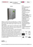
L' SPC07-IP è un regolatore di carica per applicazioni fotovoltaiche, in grado di
gestire la ricarica di batterie al piombo ermetiche/acido libero a 12Vdc, e due
carichi in corrente continua di 7A max con undici diverse configurazioni di gestione.
La rilevazione del crepuscolare è effettuata da pannello. L' algoritmo di ricarica è di
tipo PWM a Mosfet con tensione compensata in temperatura: tramite un sensore
NTC esterno (opzionale) o quello interno al circuito, che a sua volta provvede anche
ad una protezione di sovra-temperatura. L’ SPC07-IP è già provvisto di diodo di
blocco a bassa caduta che evita la scarica di batteria attraverso i moduli fotovoltaici,
al tempo stesso un controllo di Low Battery salvaguarda la batteria da scariche
profonde dovute al consumo del carico. Un led bicolore indica gli eventuali stati di
errore (rosso) e presenza di corrente di pannello (verde), due gialli l’attivazione di
ogni singolo carico.Si possono alimentare fino a due carichi 12V DC. Ciascun carico
può assorbire una corrente massima di 7 A, ma la somma della corrente assorbita
dai due carichi contemporaneamente non deve eccedere i 7 A. Il circuito è
realizzato in un compatto box con protezione IP56 gia dotato di pressa-cavi che
facilitano la connessione al pannello e alla batteria. Il regolatore è equipaggiato con
una morsettiera per cavi fino a 2,5mmq per collegamento batteria e pannello,
mentre il collegamento dei sensori più essere effettuato con cavi di sezione
massima 1,5mmq.
Connettore sensori
- Sensore di temperatura NTC esterno
- Sensore di presenza ad infrarossi
- Interruttore di abilitazione da remoto
Switch di
configurazione
Caratteristiche tecniche:
Per batterie al piombo ermetiche 12V
Max corrente di ricarica 7A
Max corrente totale sui carichi 7A
Controllo a microcontrollore
Dispositivi Mosfet
Ricarica PWM
Due carichi configurabili
Diodo di blocco integrato
Ricarica compensata in temperatura
con sensore integrato o remoto
Controllo batteria scarica
Indicatori Led
Contenitore compatto IP56
Semplicità di cablaggio
Versione
Software 2.5
Rev 2.5
Utilizzatori
Indicazioni dei Led
Un lampeggio rosso: batteria scarica
Due lampeggi rossi: sovra-tempemperatura
Verde: presenza corrente di pannello
I due led gialli indicano stato delle uscite
LoadA e LoadB
Procedura di installazione:
Il regolatore va installato in modo da non essere esposto ai raggi diretti del sole per evitarne il surriscaldamento, evitare
contatti con acqua e ambienti altamente umidi. Nell’installazione si raccomanda la massima attenzione nel rispetto delle
polarità e nell’ evitare cortocircuiti; sono distruttivi ed annullano la garanzia. Si consiglia di collegare i cavi batteria
solo dopo aver connesso tutti gli altri; non introdurre un ulteriore diodo di blocco: ciò vanifica la rilevazione del
crepuscolare. Posizionare la batteria nel luogo scelto, avendo cura di collegare adeguatamente i cavi e di minimizzare la
distanza dal regolatore di carica, il sensore di temperatura NTC esterno ( opzionale ) risulta consigliato in caso di
marcate differenze in temperatura tra regolare e banco batterie. Collegare all’apposito connettore il sensore di
temperatura NTC esterno e se richiesto dalla configurazione scelta collegare anche il sensore infrarossi (PX01) o
l’interruttore per l’abilitazione da remoto. All’accensione il led deve effettuare un lampeggio verde ed uno rosso ad
indicare una corretta accensione.
Per testare se l’installazione del regolatore è stata eseguita correttamente è necessario verificare che al crepuscolo si
accende il carico secondo configurazione impostata con gli Switchs (vedi pagina successiva). Per simulare il crepuscolo
consigliamo di coprire accuratamente il pannello PV con un cartone abbastanza spesso; potrebbe essere necessario
coprire anche la superficie posteriore del pannello PV. E’ stato riscontrato che collegando al regolatore SPC07-IP alcuni
modelli di pannelli fotovoltaici questo non riesce a rilevare la notte. Se ci si trova in tali condizioni contattare il centro
assistenza Western CO.
This document is the property of WESTERN CO. s.n.c.. All rights are reserved.
Reproduction and use of information contained within this document is
forbidden without the written consent of WESTERN CO. s.n.c..
1 di 1
04-04-2012
Rev 1.5
MANUALE UTENTE SPC07-IP
Configurazioni:
In tutte le configurazioni i seguenti processi sono garantiti:
La regolazione della tensione di carica della batteria, compensata in temperatura, dalla NTC esterna o interna.
La disattivazione del carico al raggiungimento della soglia di Low-Battery (un lampeggio rosso del Led), impostabile
a 11V (dip switch 6 ON) o 12 V (dip switch 6 OFF).
L’inibizione del sistema al raggiungimento della soglia di sovratemperatura (due lampeggi rossi del Led).
L’uscita da una condizione di batteria scarica è permessa solo di giorno.
Switchs
1
ON
1
ON
Descrizione
Caricabatteria standard *:
Schema collegamento carico
Carichi A e B sempre attivi.
+LoadA
-LoadA
Crepuscolare completo con uscite complementari *:
Carico A attivo solo di giorno.
Carico B attivo solo di notte.
+LoadB
-LoadB
SPC07-IP
1
ON
Carico remoto *:
Load A comandato dal contatto sull’ingresso Sens; chiuso verso gnd carico A attivo.
Load B sempre attivo.
Sens
OPEN
CLOSE
Gnd
Sens
+LoadA
-LoadA
OPEN
LoadA
+LoadB
-LoadB
LoadB
SPC07-IP
1
ON
Crepuscolare con sensore IR *:
Load A attivo di notte (crepuscolo rilevato dal pannello) per un tempo di 5 minuti ogni volta
che il sensore IR rileva il passaggio di una persona.
Load B attivo solo di notte.
BLU
+LoadA
-LoadA
IR Sensor
PX01
LoadA
5 min
Gnd
Sens
VERDE/GREEN
ROSSO/RED
12V Aux Max 100mA
+LoadB
-LoadB
5 min
LoadB
SPC07-IP
1
ON
Lampada accesa per tutta la notte *:
Carico attivato di notte, dal crepuscolo (rilevato dal pannello) fino all’alba.
Load B gestisce il risparmio energetico della lampada (Vedi *diagramma temporale)
LoadA
LoadB
BLU
+LoadA
-LoadA
IR Sensor
PX01
timer
2 min
Gnd
Sens
VERDE/GREEN
ROSSO/RED
12V Aux Max 100mA
+LoadB
-LoadB
2 min
SPC07-IP
Lampada alla massima luminosità/Lamp to max Brightness
Lampada in risparmio di energia, metà luminosità/Lamp in energy save, half
brightness
Lampada spenta/Lamp off
1
ON
ON
Crepuscolare con timer 6h *:
Carico attivato di notte, dal crepuscolo (rilevato dal pannello) per 6 ore.
Load B gestisce il risparmio energetico della lampada (Vedi *diagramma temporale)
1
LAMP
12 LED
DIMMER
GND
12V
Si può escludere il risparmio energetico non connettendo
il segnale dimmer. In questo modo la lampada rimarrà
accesa per tutto il tempo del timer alla massima
luminosità:
Crepuscolare con timer 8h *:
Load attivato di notte, dal crepuscolo (rilevato dal pannello) per 8 ore.
Load B gestisce il risparmio energetico della lampada (Vedi *diagramma temporale)
1
ON
Gnd
Sens
+LoadA
-LoadA
Crepuscolare con timer 8h ritardo 1h *:
Load attivato di notte un’ora dopo il crepuscolo (rilevato dal pannello) per 8 ore.
Load B gestisce il risparmio energetico della lampada (Vedi *diagramma temporale)
1
ON
Crepuscolare con timer 10h *:
Load attivato di notte, dal crepuscolo (rilevato dal pannello) per 10 ore.
Load B gestisce il risparmio energetico della lampada (Vedi *diagramma temporale)
+LoadB
-LoadB
LAMP
12 LED
DIMMER
GND
12V
SPC07-IP
*diagramma temporale
LoadA
LoadB
timer
2 min
2 min
Lampada alla massima luminosità/Lamp to max Brightness
Lampada in risparmio di energia, metà luminosità/Lamp in energy save, half
brightness
Lampada spenta/Lamp off
1
ON
Carichi lampeggianti al 50% ( 0,5s A acceso e B spento, 0,5s A spento e B acceso). Dal
crepuscolo (rilevato dal pannello) e per tutto il periodo di buio, si dimezza la potenza erogata
ai carichi.
1
ON
Lampeggiatore stradale alternato 50% *:
Semaforo/
Semaphore
+LoadA
-LoadA
Lampeggiatore stradale alternato flash *:
Carichi lampeggianti alternati con un flash di 20ms per ogni secondo. Dal crepuscolo (rilevato
dal pannello) e per tutto il periodo di buio, è ridotta la potenza erogata ai carichi.
+LoadB
-LoadB
SPC07-IP
* ATTENZIONE : Le configurazioni in tabella sono valide per regolatori con versione software 2.5 in poi (vedi immagine nella pag. precedente per
individuare la versione dell’SPC07-IP in Vostro possesso). Per documentazione su versioni antecedenti alla 2.5, rivolgersi al centro assistenza
Western CO, o fare riferimento all’etichetta sul retro del coperchio del regolatore.
This document is the property of WESTERN CO. s.n.c.. All rights are reserved.
Reproduction and use of information contained within this document is
forbidden without the written consent of WESTERN CO. s.n.c..
2 di 2
04-04-2012
Rev 1.5
MANUALE UTENTE SPC07-IP
Connessione ricarica
Temerature sensor
+
Opzionale, collegare solo se la batteria è
connessa a più di 3M dal regolatore
Gnd
Text
Gnd
Sens
+LoadA
-LoadA
+Pan
-Pan
AuxIR
+Batt
-Batt
+LoadB
-LoadB
-
+
-
12V
SPC07-IP
Dopo aver collegato la batteria e il pannello come schema a
lato, verificare che, quando il pannello è esposto alla luce del
sole, si accende verde il led di segnalazione, ad indicare che il
pannello fotovoltaico stà fornendo corrente alla batteria.
Descrizione morsetti:
+Pan / -Pan
Ingresso pannello fotovoltaico
+Batt / -Batt
Ingresso batteria
+LoadA / -LoadA Uscita carico A
+LoadB / -LoadB Uscita carico B
Text
Ingresso sonda temperature
Sens
Ingresso comando IR / carico remoto
AuxIR
uscita ausiliaria 12V Max 100mA
alimentazione sensore IR
Caratteristiche Elettriche:
CARATTERISTICHE
SIM
CONDIZIONE
MIN
Alimentazione Batteria Pb; Tensione di lavoro
Corrente di lavoro
VDD 12V
IDD no carico, no pannelli, VDD=13V
IDLB no carico, no pannello, batteria scarica VDD=12V
no carico, no pannelli, batteria scarica VDD=10V
Tensione pannelli
VPAN
Corrente Pannelli
IPAN T=25°C
Tensione di soglia batteria scarica
VLB Tensione presente per almeno 5sec. 30% di scarica
Tensione presente per almeno 5sec. 70% di scarica
Tensione di soglia fine stato di batteria scarica
VELB Temperatura 25°C
Corrente sul carico
VLD Alimentazione continua
Corrente di picco sul carico
VPL max. time 120ms.; Tcase=25°C
Tensione di fine carica
VECH Temperatura Batteria 25°C ±2°C
Compensazione tensione in Temperatura
VTadj TBATT>=-8°C<=60°C
Tens. soglia su pan per attivazione crepuscolare VTD
Tens. soglia su pan per disattivaz. crepuscolare VTL
Temperatura ambiente di lavoro
Sezione conduttori di potenza
TA
-
TIP
5
12
6
6.3
4,5
5
5
5,2
0
17,2
0
7
<11,9 <12
<10,9 <11
>13,7 >13,8
0
6
13,8 14,1
-20
<3,2 <3,4
>6,5 >6,7
MAX
UNIT
15
V
6,5
mA
5,5
mA
5,4
mA
22
V
A
<12,1
V
<11,1
V
>13,9
V
7
A
70
A
14,4
V
mV/°C
<3,6
V
>6,9
V
-10
-
2,5
60
-
°C
mm2
-
300
-
g
Peso
Dimensioni meccaniche
59
88
128
PG9
PG9
PG9
25
PG9
WESTERN CO. snc
Via Pasubio 1
Recapito:
63037 San Benedetto del Tronto (AP)
tel 0735 751248 fax 0735 751254
e-mail: [email protected]
web: www.western.it
This document is the property of WESTERN CO. s.n.c.. All rights are reserved.
Reproduction and use of information contained within this document is
forbidden without the written consent of WESTERN CO. s.n.c..
3 di 3
SPC07IP Technical Manual
04-04-2012
Rev 1.5
Photovoltaic regulator up to 120W /12V power modules
General Description:
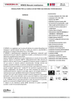
SPC07-P is a charge regulator for 12Vdc PV applications. It is able to manage
the recharge of Pb batteries and two different DC loads of max 7A total current,
with eleven different configurations. “Light sensor” detection is made by the
module.
The recharge algorithm is PWM - Mosfet with voltage compensated in
temperature: through an external NTC sensor (optional) or through the sensor
inside the circuit which supply also a protection against over-temperature.
SPC07-P includes also a blocking diode to avoid the discharge of battery
through the PV modules; at the same time a Low-Battery control save the
battery from deep discharges caused by the load consumption.
A bi-coloured LED shows eventual status of error (red colour) and presence of
panel current (green colour), two yellow LEDS show the activation of each load.
SPC07-P can simultaneously power two independent 12V DC loads with total
current limited to max 7Amp, if only one load is used the maximum current of
7A can be supplied to this one.
The circuit is inside a IP56 compact box which has already got chocks to have
an easy connection to PV module and battery.
The regulator is equipped with a connection board with cables up to 2,5mmq for
battery and panel, while the connection of sensors can be made using cables of
1,5mmq max section.
Sensors connector
- External NTC temperature sensor
- Infra-red sensor
- Switch for remote mode
Configuration
switch
Technical Features:
12V sealed Pb batteries
Max recharge current: 7A
Max total current on loads:
7A
Microcontroller design
Mosfet devices
PWM system charge
No. 02 selectable loads
Integrated blocking diode
Recharge compensated in
temperature with either
integrated or remote
sensor
Low battery control
LED indicators
Compact box IP56
Easy wiring
Version
Software 2.5
Rev 2.5
Loads
LEDs indications
One red lighting: low battery
Two red lightings: over-tempemperature
Green: presence of panel current
Yellow leds for load state LoadA and
LoadB
Installation procedure:
Avoid direct exposure to sunrays (caution: over-heating), avoid water and humid environments.
PAY ATTENTION TO POLARITIES AND AVOID SHORT-CIRCUITS; they are destructive and cancel warranty.
Connect the battery cables only after having connected all the others; do not insert a further blocking diode: you would
annul the “light sensor” detection. Put the battery in the chosen place, connecting in the proper way the cables and
reducing the distance from the charge regulator more that you can.
We advise the external NTC temperature sensor ( optional ) in case of big differences in temperature between regulator
and batteries. Connect to the proper connector the external NTC temperature sensor and, if requested by the chosen
configuration, connect also either the infrared sensor (PX01) or the switch for remote habilitation. On starting the LED
must effect a green and red lightning to indicate a correct power on.
To test if the installation of the regulator has been made in the right way it is necessary to verify that at sunset the load
switches on according to the configuration that has been set by the Switches (ser the following page).
To simulate SUNSET we advise to cover carefully the PV module using a quite thick cardboard; it could be necessary to
cover even the rear side of the PV module. We saw that if you connect to the regulator SPC07IP some kind of PV
modules the regulator is not able to detect the night. If you are in such conditions, please contact Western Co. Service
Center.
This document is the property of WESTERN CO. s.n.c.. All rights are reserved.
Reproduction and use of information contained within this document is
forbidden without the written consent of WESTERN CO. s.n.c..
1 di 3
SPC07IP Technical Manual
04-04-2012
Rev 1.5
Configurations:
In all configurations the following processes are guaranteed:
The regulation of the battery’s charge voltage, compensated in temperature, by external or internal NTC.
Load deactivation at reaching Low-Battery threshold (a red ligthning), selectable to 11V (dip switch 6 ON) or 12 V
(dip switch 6 OFF).
System inhibition at reaching Overtemperature threshold (two red ligthnings of the LED).
It is possible to exit from a low battery condition only during daylight.
Switchs
1
ON
ON
1
Description
Standard battery charger*:
Scheme of load connection
Loads A and B always on.
+LoadA
-LoadA
Complete “light sensor” with complementary outputs*:
Load A ON only during day.
Load B ON only during night.
+LoadB
-LoadB
SPC07-IP
ON
1
Remote load *:
The load is controlled by the contact on Sens input; closed to gnd => load A ON, opened =>
load A OFF. Load B always ON.
Sens
OPEN
CLOSE
Gnd
Sens
+LoadA
-LoadA
OPEN
LoadA
+LoadB
-LoadB
LoadB
SPC07-IP
ON
1
Light sensor with IR *:
Load A ON during night (“light sensor” by the panel) for 5 minutes every time the IR sensor
notices the passage of a person.
Load B ON only during night.
BLU
+LoadA
-LoadA
IR Sensor
PX01
LoadA
5 min
Gnd
Sens
VERDE/GREEN
ROSSO/RED
12V Aux Max 100mA
+LoadB
-LoadB
5 min
LoadB
SPC07-IP
ON
1
Lamp ON for all night long*:
Load activated during night, from sunset (detected by the PV module) until sunset.
LOAD B manages the lamp energy saving LoadA
BLU
2 min
+LoadA
-LoadA
IR Sensor
PX01
timer
LoadB
Gnd
Sens
VERDE/GREEN
ROSSO/RED
12V Aux Max 100mA
+LoadB
-LoadB
2 min
SPC07-IP
Lamp to max Brightness
Lamp in energy save, half brightness
LAMP
12 LED
Lamp off
ON
ON
ON
ON
1
Light sensor with timer 6h *:
Load ON during night, from sunset (revealed by the module) for 6 hours.
Load B manages the lamp energy saving (see * temporal diagram)
1
DIMMER
GND
12V
You can exclude the Energy saving not connecting the
dimmer signal. In this way the lamp will remain ON for all
the time of the timer at its maximum luminosity.
Light sensor with timer 8h *:
Gnd
Sens
Load ON during night, from sunset (revealed by the module) for 8 hours.
Load B manages the lamp energy saving (see * temporal diagram)
1
+LoadA
-LoadA
Light sensor with timer 8h delay 1h *8
+LoadB
-LoadB
Load ON during night, one hour after sunset (revealed by the module) for 3 hours.
Load B manages the lamp energy saving (see * temporal diagram)
1
Light sensor with timer 10h *:
SPC07-IP
Load ON during night, from sunset (revealed by the module) for 10 hours.
Load B manages the lamp energy saving (see * temporal diagram)
LAMP
12 LED
DIMMER
GND
12V
*(see temporal diagram)
LoadA
timer
LoadB
2 min
2 min
Lamp to max Brightness
Lamp in energy save, half brightness
Lamp off
ON
ON
1
Road flashing indicator - alternated 50% *:
Lightning loads at 50% ( 0,5s A on and B off, 0,5s A off and B on). From twilight (“light sensor”
by the panel) and for the whole period of darkness, the power supplied to loads is reduced to
a half.
1
Road flashing indicator - alternated flash *:
Alternating lighting loads with a flash of 20ms for each second. From twilight (“light sensor”
by the panel)and for the whole period of darkness, the power supplied to loads is reduced.
Semaforo/
Semaphore
+LoadA
-LoadA
+LoadB
-LoadB
SPC07-IP
* WARNING
: The configurations in the table are valid for regulators with software versions from 2.5 onwards (see
image in the previous page to understand the version of your SPC07IP). To have technical documentation concerning
previous versions, call Western Co. service center.
This document is the property of WESTERN CO. s.n.c.. All rights are reserved.
Reproduction and use of information contained within this document is
forbidden without the written consent of WESTERN CO. s.n.c..
2 di 3
SPC07IP Technical Manual
Recharge connection
Temperature sensor
+
connect only if battery distance is
grater then 3 meter.
Gnd
Text
Gnd
Sens
+LoadA
-LoadA
+Pan
-Pan
AuxIR
+Batt
-Batt
+LoadB
-LoadB
-
+
-
12V
SPC07-IP
04-04-2012
Rev 1.5
After having connected battery and module as you can see in
the scheme on the left side, verify that the signaling green LED
in ON when the PV module is exposed to sunlight; this shows
that the PV module is supplying current to the battery.
Terminals description:
+Pan / -Pan
PV module input
+Batt / -Batt
Battery input
+LoadA / -LoadA Load A output
+LoadB / -LoadB Load B output
Text
Temperature sensor input
Sens
Input of IR command / remote load
AuxIR
Auxiliary output - 12V Max 100mA
power supplying IR sensor
Electric Features:
FEATURES
SYM CONDITION
Power supply Pb Battery ; Working voltage
Working current
VDD 12V
IDD no load, no panels, VDD=13V
IDLB no load, no panel, discharged battery VDD=12V
no load, no panels, discharged battery VDD=10V
VPAN
IPAN T=25°C
VLB Voltage present for at least 5sec. 30% of discharge
Voltage present for at least 5sec. 70% of discharge
VELB Temperature 25°C
VLD Continuous power supply
VPL max. time 120ms.; Tcase=25°C
VECH Battery temperature 25°C ±2°C
VTadj TBATT>=-8°C<=60°C
VTD
VTL
Panels voltage
Panels current
Low-battery voltage threshold
Voltage threshold end low battery
Total current load
Peak current load
End recharge voltage
Temperature coefficent for recharge voltage
Volt treshold on pannel for twilight ON
Volt treshold on pannel for twilight OFF
Working environment temperature
Section of power conductors
MIN
TA
-
TIP
5
12
6
6.3
4,5
5
5
5,2
0
17,2
0
7
<11,9 <12
<10,9 <11
>13,7 >13,8
0
6
13,8 14,1
-20
<3,2 <3,4
>6,5 >6,7
MAX
UNIT
15
6,5
5,5
5,4
22
<12,1
<11,1
>13,9
7
70
14,4
<3,6
>6,9
V
mA
mA
mA
V
A
V
V
V
A
A
V
mV/°C
V
V
-10
-
2,5
60
-
°C
2
mm
-
300
-
g
Weight
Mechanic dimensions:
59
88
128
PG9
PG9
PG9
25
PG9
WESTERN CO. snc
Via Pasubio 1
Address:
63039 San Benedetto del Tronto (AP) - Italy
Tel. +39 0735 751248 Fax +39 0735 751254
e-mail: [email protected]
web: www.western.it
This document is the property of WESTERN CO. s.n.c.. All rights are reserved.
Reproduction and use of information contained within this document is
forbidden without the written consent of WESTERN CO. s.n.c..
3 di 3