1
5
6
Conexión de la alimentación de PoE
Conecte la alimentación PoE de 48 V a los
bornes 1 (+) y 2 (-). Los bornes están puenteados dentro del módulo. Los puentes se
hallan entre los bornes 1 y 3, así como entre los bornes 2 y 4.
7
Asignación de la interfaz POE-RJ45
Pin
1
2
3
4
5
6
7
8
Asignación
RX+ / 48 V CC
RX- / 48 V CC
TX+ / 0 V
n. c.
n. c.
TX- / 0 V
n. c.
n. c.
Descripción
Datos/PoE +
Datos/PoE +
Datos/PoE Datos/PoE-
Français
DE
EN
FR
IT
ES
Art.-Nr. 2832904
Einbauanweisung für den Elektroinstallateur
Installation notes for electrical personnel
Instructions d’installation pour l’électricien
Istruzioni di installazione per l’elettricista
Instrucciones de montaje para el instalador eléctrico
1
2
Modulo di interfaccia Power over Ethernet (PSE) per l'alimentazione Endspan
Avvertenze sulla sicurezza e sui pericoli
Enchufar la alimentación de PoE
El conector macho de alimentación de PoE
se halla en la parte inferior del módulo de
interfaz. Al enchufarlo observe la codificación del conector macho.
Indicaciones de diagnóstico y estado
Un LED verde por puerto Id. PoE
AUTOMATION
FL IF 2PSE-F
Nel maneggiare elementi a rischio di scariche elettrostatiche, osservare
le necessarie misure di sicurezza (EN 61340-5-1 e EN 61340-5-2,
nonché IEC 61340-5-1 e IEC 61340-5-2)!
Il modulo è concepito esclusivamente per l'esercizio con il Modular
Managed Switch. Il collegamento a terra del modulo avviene con il collegamento sulla stazione di testa o sul modulo di espansione.
Per ulteriori informazioni tecniche consultare il manuale utente per
FL SWITCH MM HS all'indirizzo www.download.phoenixcontact.it.
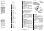
1 Guide
4 Porte Ethernet PoE
2 Linguette di bloccaggio
5 LED per riconoscimento PoE
3 Cartellino di siglatura
6 Connessione alimentazione PoE
7 Slot per stazione di testa/espansione
3
7
1
6
Módulo de interfaz Power Over Ethernet (PSE) para alimentación de Endspan
5
Indicaciones y advertencias de seguridad
DE
EN
FR
IT
ES
¡Observe las medidas preventivas necesarias al manipular elementos
expuestos a peligro de descarga electrostática (EN 61340-5-1 y
EN 61340-5-2 así como IEC 61340-5-1 y IEC 61340-5-2)!
El módulo ha sido concebido para ser usado únicamente con el sistema
modular de switches. La toma de tierra del módulo se produce al montarlo sobre la estación principal o sobre el módulo de ampliación.
Encontrará más información técnica en el manual del FL SWITCH MM HS en
www.download.phoenixcontact.es.
1 Placas guía
4 Puertos Ethernet PoE
2 Anclajes de encastre
5 LEDs para identificación de PoE
3 Casilla de inscripción
6 Conexión de alimentación de PoE
7 Slot para estación principal o ampliación
A. WARNING - EXPLOSION HAZARD - DO NOT DISCONNECT EQUIPMENT UNLESS
POWER HAS BEEN SWITCHED OFF OR THE AREA IS KNOWN TO BE NONHAZADOUS:
B. These devices are intended to be installed within an enclosure rated at least IP54.
C.
1. Phoenix Contact GmbH & Co. KG
2. 2832904, FL IF 2PSE-F
3. 48 V dc, 10 mA, Wire Range(AWG): 28-16
4. Ambient temperature range: -20°C < Tamp < +55°C
5. Date code or serial number referencing date of manufacture: see device or package
6. Cl. I, Zn. 2, AEx nC IIC T4 / Ex nC IIC T4 X, Cl. I, Div. 2, Grp. A-D
7. Temp. Code - T4
D. Provisions shall be made to prevent the rated voltage from being exceeded by transient
disturbances of more than 40%.
E. Wire Range (AWG): 28-16
Technische Änderungen vorbehalten!
Technical modifications reserved!
Sous réserve de modifications techniques !
Con riserva di modifiche tecniche!
¡Reservado el derecho a las modificaciones técnicas!
© PHOENIX CONTACT 09/2007
MNR 9029415 - 02
724502
2
4
Power-over-Ethernet-Interface-Modul (PSE) zur Endspan-Energieversorgung
Sicherheits- und Warnhinweise
Deutsch
Conexión de los conectores RJ45
Enchufe el conector macho RJ45 al conector hembra hasta que encaje, observando
sus correspondientes codificaciones.
Desmontaje de los conectores RJ45
Presione la pestaña de encaje en dirección
al conector macho y retire seguidamente el
conector.
Observer les mesures de précaution nécessaires lors du maniement
des composants sensibles aux décharges électrostatiques
(EN 61340-5-1 et EN 61340-5-2 ainsi que CEI 61340-5-1 et
CEI 61340-5-2).
Le module est uniquement conçu pour fonctionner avec un système
modulaire de switches. La mise à la terre du module se fait par encliquetage sur la tête de station ou sur le module d'extension.
Pour de plus amples informations techniques, voir le manuel d'utilisation du
FL SWITCH MM HS sous www.download.phoenixcontact.fr.
1 Guides
4 Ports Ethernet PoE
2 Languette d'encliquetage
5 DEL de reconnaissance PoE
3 Champ de repérage
6 Raccordement alimentation PoE
7 Emplacement pour tête de station/module d'extension
Beachten Sie die notwendigen Vorsichtsmaßnahmen bei der
Handhabung elektrostatisch gefährdeter Bauelemente (EN 61340-5-1
und EN 61340-5-2)!
Das Modul ist ausschließlich zum Betrieb mit dem Modular Managed
Switch System vorgesehen. Die Erdung des Moduls erfolgt mit dem
Aufstecken auf die Kopfstation oder auf das Erweiterungsmodul.
Weiterführende technische Informationen finden Sie im Handbuch zum
FL SWITCH MM HS unter www.download.phoenixcontact.de.
1 Führungsstege
4 Ethernet-PoE-Ports
2 Rastlaschen
5 LEDs für PoE-Erkennung
3 Beschriftungsfeld
6 Anschluss PoE-Versorgung
7 Steckplatz für Kopfstation/Erweiterung
Power-over-Ethernet interface module (PSE) for endspan power supply
Safety and warning instructions
English
4
Liberación de los módulos de interfaz
Afloje el tornillo de fijación.
Desmontaje de los módulos de interfaz
Presione el anclaje (A) y tire con cuidado
del módulo para sacarlo (B).
Italiano
3
Español
2
Montaje
Conecte los módulos de interfaz sobre los
slots de los módulos base. Al hacerlo, las
placas guía de la parte superior de los módulos deben introducirse con cuidado y sin
torcerlas en las ranuras guía del módulo
base. Deslice ahora los módulos de interfaz perpendicularmente en dirección al
módulo base, hasta que el conector macho
y la sujeción hayan encastrado.
Fijación de los módulos de interfaz
Fije el módulo de interfaz con el tornillo que
está en la parte de abajo, a la derecha.
Consignes de sécurité et avertissements
English
1
PHOENIX CONTACT GmbH & Co. KG
32823 Blomberg, Germany
Phone
+49-(0)5235-3-00
Fax
+49-(0)5235-3-41200
www.phoenixcontact.com
Module interface Power over Ethernet (PSE) pour alimentation endspan
Español
Observe the necessary safety precautions when handling components
that are vulnerable to electrostatics (EN 61340-5-1 and EN 61340-5-2,
as well as IEC 61340-5-1 and IEC 61340-5-2)!
The module is intended exclusively for use with the Modular Managed
Switch System. The module is grounded by attaching it to the head station or the extension module.
Further technical information can be found in the manual of the
FL SWITCH MM HS at www.download.phoenixcontact.com.
1 Guide bars
4 Ethernet PoE ports
2 Latches
5 LEDs for PoE recognition
3 Labeling field
6 PoE supply connector
7 Slot for head station/extension
Deutsch
1
2
2
1
1
2
1
2
3
3
4
4
2
1
A
1
5
B
2
1
2
3
4
1
2
8
n. c.
Pin 8
n. c.
Pin 7
TX- / 0 V
Pin 6
n. c.
Pin 5
n. c.
Pin 4
TX+ / 0 V
Pin 3
RX- / +48 VDC Pin 2
RX+ / +48 VDC Pin 1
724502
Lösen der Interface-Module
Lösen Sie die Befestigungsschraube.
Entfernen der Interface-Module
Drücken Sie die Rastlasche (A) und ziehen
Sie das Modul vorsichtig ab (B).
3
Stecken der PoE-Versorgung
Der Stecker der PoE-Versorgung befindet
sich an der Unterseite des InterfaceModuls. Beachten Sie beim Stecken die
Codierung des Steckers.
2
4
RJ45
Français
Installation
Insert the interface modules onto the slots
of the basic modules. The guide bars on the
upper side of the interface modules must be
inserted into the guide slots on the basic
module without jamming it in any way. Now
push the interface modules vertically in the
direction of the basic module, until the connector and the latch have clicked into place.
Securing the interface modules
Secure the interface module with the screw
on its bottom right.
1
Loosening the interface modules
Loosen the mounting screw.
Removing the interface modules
Press the latch (A) and carefully remove the
module (B).
3
Connecting the RJ45 connectors
Push the RJ45 male connector into the female connector until it is engaged, paying
attention to the encoding.
Removing the RJ45 connectors
Push the latch toward the connector and
then remove the connector.
5
Diagnose- und Status-Anzeigen
Grüne LED je Port
PoE-Erkennung
PoE supply connector
The connector for the PoE supply is located
at the bottom of the interface module. Pay
attention to the encoding on the connector
when plugging it in.
Anschließen der PoE-Versorgung
Schließen Sie die 48-V-PoE-Versorgung
an die Klemmen 1 (+) und 2 (-) an. Die
Klemmen sind im Modul gebrückt. Die
Brücken befinden sich zwischen Klemme 1
und 3 sowie zwischen Klemme 2 und 4.
6
Connecting the PoE supply
Connect the 48 V PoE supply to terminal
1 (+) and 2 (-). The terminals are bridged
within the module. The jumpers are located
between terminal 1 and 3, and between
terminal 2 and 4.
7
Belegung der RJ45-POE-Schnittstelle
7
Assignment of the RJ45 POE interface
Pin
1
2
3
4
5
6
7
8
Belegung
RX+ / 48 V DC
RX- / 48 V DC
TX+ / 0 V
n. c.
n. c.
TX- / 0 V
n. c.
n. c.
Beschreibung
Daten/PoE +
Daten/PoE +
Daten/PoE Daten/PoE-
2
4
Pin
1
2
3
4
5
6
7
8
Assignment
RX+ / 48 V DC
RX- / 48 V DC
TX+ / 0 V
n. c.
n. c.
TX- / 0 V
n. c.
n. c.
Description
Data/PoE +
Data/PoE +
Data/PoE Data/PoE -
Italiano
Montage
Insérer les modules interface sur les emplacements des modules de base. Les guides situés sur la partie supérieure des
modules interface doivent être insérés
avec soin et sans bloquer dans les rainures
du module de base. Pousser ensuite les
modules interface perpendiculairement
vers le module de base jusqu'à ce que le
connecteur et la barrette de retenue s'encliquettent.
Fixation des modules interface
Fixer le module interface à l'aide de la vis
située en bas à droite.
1
Desserrage des modules interface
Dévisser la vis de fixation.
Retrait des modules interface
Appuyer sur la languette d'encliquetage (A)
et retirer précautionneusement le module
(B).
3
Raccordement des connecteurs RJ45
Enficher le connecteur RJ45 dans le connecteur femelle en respectant le codage,
jusqu'à encliquetage.
Retrait des connecteurs RJ45
Appuyer sur l'ergot d'encliquetage en direction du connecteur (A) et retirer ensuite
le connecteur.
5
Diagnostics and status indicators
Green LED for each port PoE recognition
6
48 V DC
7
1
Anschluss der RJ45-Stecker
Stecken Sie den RJ45-Stecker unter
Beachtung der Codierung in die Buchse
bis er einrastet.
Entfernen der RJ45-Stecker
Drücken Sie die Rastnase in Richtung des
Steckers und ziehen Sie dann den Stecker
ab.
5
6
English
Montage
Stecken Sie die Interface-Module auf die
Steckplätze der Grundmodule. Dabei müssen die Führungsstege auf der Oberseite
der Interface-Module vorsichtig und ohne
zu Verkanten in die Führungsnuten am
Grundmodul gesteckt werden. Schieben
Sie nun die Interface-Module senkrecht in
Richtung des Grundmoduls, bis der Stekker und die Haltespange eingerastet sind.
Sichern der Interface-Module
Sichern Sie das Interface-Modul mit der
Schraube unten rechts am InterfaceModul.
Enfichage de l'alimentation PoE
Le connecteur de l'alimentation PoE se situe sur la face inférieure du module interface. Respecter le codage lors de l'enfichage
du connecteur.
2
4
Montaggio
Inserire i moduli di interfaccia negli slot dei
moduli di base. Innestare con cautela le
guide sul lato superiore dei moduli di interfaccia nelle scanalature principali del modulo di base, facendo attenzione a non
stortarle. Spingere quindi i moduli di interfaccia perpendicolarmente in direzione del
modulo di base, fino a quando il connettore
maschio e il dispositivo di fissaggio non si
incastrano.
Fissaggio dei moduli di interfaccia
Fissare il modulo di interfaccia mediante la
vite in basso a destra posta sul medesimo.
Allentamento dei moduli di interfaccia
Svitare le viti di fissaggio.
Rimozione dei moduli di interfaccia
Premere la linguetta di bloccaggio (A) ed
estrarre delicatamente il modulo (B).
Collegamento dei connettori RJ45
Tenendo conto della codifica, inserire il
connettore RJ45 nel connettore femmina
finché non si incastra.
Rimozione dei connettori maschio RJ45
Spingere la linguetta di incastro in direzione del connettore e successivamente rimuovere il connettore.
5
Voyants de diagnostic et d'état
DEL verte pour chaque port
Reconnaissance PoE
Connessione dell'alimentazione PoE
Il connettore dell'alimentazione PoE si trova sul lato inferiore del modulo di interfaccia. Per la connessione, tenere in
considerazione la codifica del connettore.
LED di diagnosi e di stato
Un LED verde per porta
Riconoscimento PoE
6
Raccordement de l'alimentation PoE
Raccorder l'alimentation PoE 48 V aux bornes 1 (+) et 2 (-). Les bornes sont strappées dans le module. Les straps se
trouvent entre les bornes 1 et 3 ainsi
qu'entre les bornes 2 et 4.
6
Collegamento dell'alimentazione PoE
Collegare l'alimentazione PoE di 48 V ai
morsetti 1 (+) e 2 (-). I moduli sono ponticellati nel modulo. I ponticelli si trovano tra il
morsetto 1 e 3 nonché tra il morsetto 2 e 4.
7
Affectation de l'interface POE RJ45
7
Assegnamento dell'interfaccia POE
RJ45
Broche
1
2
3
4
5
6
7
8
Affectation
Description
RX+ / 48 V DC
RX- / 48 V DC
TX+ / 0 V
n. c.
n. c.
TX- / 0 V
n. c.
n. c.
Données/PoE+
Données/PoE+
Données/PoEDonnées/PoE-
Pin
1
2
3
4
5
6
7
8
Assegnamento
RX+ / 48 V DC
RX- / 48 V DC
TX+ / 0 V
n. c.
n. c.
TX- / 0 V
n. c.
n. c.
Descrizione
Dati/PoE +
Dati/PoE +
Dati/PoE Dati/PoE -