1
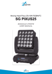
Matrix Panel 25x10W RGBW/FC SG PIXI5 MANUALE UTENTE USER MANUAL Rev. 01-06/15 INDICE: 1. INTRODUZIONE p. 3 2. ISTRUZIONI DI SICUREZZA p. 4 3. APERTURA CONFEZIONE E CONTROLLO p. 6 4. INSTALLAZIONE ED ACCENSIONE p. 7 5. ISTRUZIONI PER L'USO p. 9 6. ACCOPPIANENTO p. 13 7. MANUTENZIONE p. 15 8. SPECIFICHE TECNICHE p. 15 INDEX: 1. INTRODUCTION p. 16 2. SAFETY INSTRUCTIONS p. 17 3. OPENING AND CONTROL p. 19 4. INSTALLATION AND SWITCH ON p. 20 5. SETUP p. 22 6. COMBINATION p. 26 7. MAINTENANCE p. 28 8. TECHNICAL SPECIFICATIONS p. 28 2 1. INTRODUZIONE Grazie per avere scelto un nostro prodotto! Vi preghiamo di fare riferimento alle istruzioni e alle avvertenze contenute nel presente manuale per l’utilizzo del dispositivo e di conservarlo per future consultazioni. Il presente manuale contiene informazioni riguardanti l’installazione e l’utilizzo del dispositivo. Le informazioni contenute in questo documento sono state attentamente redatte e controllate. Tuttavia non è assunta alcuna responsabilità per eventuali inesattezze. Tutti i diritti sono riservati e questo documento non può essere copiato, fotocopiato, riprodotto o per intero o in parte senza previo consenso scritto della PROEL. PROEL si riserva il diritto di apportare senza preavviso cambiamenti e modifiche estetiche, funzionali o di design a ciascun proprio prodotto. PROEL non assume alcuna responsabilità sull’uso o sull’applicazione dei prodotti qui descritti. Il simbolo del cassonetto barrato, riportato sul prodotto o sulla documentazione, indica che il prodotto non deve essere smaltito con altri rifiuti domestici al termine del ciclo di vita. Per evitare eventuali danni all’ambiente si invita l’utente a separare questo prodotto da altri tipi di rifiuti e di riciclarlo in maniera responsabile per favorire il riutilizzo sostenibile delle risorse materiali. Gli utenti domestici sono invitati a contattare il rivenditore presso il quale è stato acquistato il prodotto o l’ufficio locale preposto per tutte le informazioni relative alla raccolta differenziata e al riciclaggio per questo tipo di prodotto. Gli utenti aziendali sono invitati a contattare il proprio fornitore e verificare i termini e le condizioni del contratto di acquisto. Questo prodotto non deve essere smaltito unitamente ad altri rifiuti commerciali. Il simbolo del lampo con freccia in un triangolo equilatero intende avvertire l'utilizzatore della presenza di "tensioni elettriche pericolose" non isolate all'interno dell'involucro del prodotto, che possono avere una intensità sufficiente a costituire rischio di scossa elettrica alle persone. Il punto esclamativo in un triangolo equilatero intende avvertire l'utilizzatore della presenza di importanti istruzioni per l'utilizzo e la manutenzione nella documentazione che accompagna il prodotto. Il simbolo della F indica che è consentito il montaggio dell’apparecchio su superfici normalmente infiammabili. Il prodotto a cui questo manuale si riferisce è conforme alle Direttive Europee di cui sono oggetto relative alla sicurezza delle apparecchiature alimentate in Bassa Tensione (LVD) ed alla compatibilità elettromagnetica (EMC) 3 2. ISTRUZIONI DI SICUREZZA Attenzione! Questo prodotto non è adatto ad un uso domestico. Leggere il presente manuale prima di installare e dare corrente all’apparecchiatura, seguire le precauzioni di sicurezza elencate di seguito ed osservare tutti gli avvertimenti indicati nel presente manuale e stampati sull’apparecchiatura. Si prega di contattare un distributore PROEL per ricevere assistenza riguardo qualsiasi dubbio su come attivare l’apparecchiatura in modo sicuro. Rivolgersi ad un tecnico qualificato per qualsiasi operazione di manutenzione non descritta nel presente manuale. Non modificare l’apparecchiatura e non installare accessori e kit di aggiornamento che non siano quelli originali PROEL. Le persone coinvolte nell’installazione e nella manutenzione del dispositivo devono: - Essere qualificate - Seguire le istruzioni del presente manuale nei teatri, nelle sale, nei luoghi in cui si svolgono gli eventi, ecc. VERIFICHE PRIMA DELL'INSTALLAZIONE Assicurarsi che tutte le parti per il fissaggio del prodotto siano in buone condizioni. Assicurarsi che il punto di ancoraggio sia stabile prima di posizionare il prodotto. Il cavo di sicurezza deve essere debitamente agganciato al dispositivo e fissato alla struttura di sostegno in modo che, in caso di cedimento del sistema di supporto primario, si abbia la minore caduta possibile del dispositivo. Se il cavo di sicurezza si usura, deve essere sostituito con un ricambio originale. DISTANZA MINIMA DEGLI OGGETTI ILLUMINATI Il proiettore deve essere posizionato in modo tale che gli oggetti investiti dal fascio di luce siano ad almeno 1 metro dalle lenti del proiettore. DISTANZA MINIMA DA MATERIALI INFIAMMABILI Il prodotto deve essere posizionato in modo tale che qualsiasi materiale infiammabile sia ad almeno 0,50 metri da qualsiasi punto della superficie del dispositivo. Non porre mai filtri o altri materiali sopra le lenti o sull’asse ottico. SUPERFICI DI MONTAGGIO Adatto per il montaggio su superfici con caratteristiche ignifughe normali e/o infiammabili. TEMPERATURE DI RIFERIMENTO Il range di temperatura ambiente d'utilizzo del dispositivo varia tra +5°C (min) e +40°C (max), al di fuori di tale intervallo l'apparecchio non deve essere utilizzato. La temperatura massima dell’alloggiamento Tb=80°C non deve mai essere superata. Non ostruire le ventole di scarico, garantire uno spazio libero di almeno 0,5 metri attorno ai fori di aerazione. 4 CLASSE DI PROTEZIONE IP20 Il dispositivo è protetto contro la penetrazione di corpi solidi di dimensioni superiori a 12 mm (0.47”) di diametro (prima cifra 2), ma non contro la caduta di gocce d’acqua, pioggia, schizzi o getti d’acqua (seconda cifra 0). Usare solo in ambienti asciutti. Usare solo all’interno. Non esporre l’apparecchiatura a pioggia o ad umidità. PROTEZIONE CONTRO LE SCOSSE ELETTRICHE Il dispositivo deve essere collegato ad un sistema di alimentazione dotato di un’efficiente messa a terra. Inoltre, si consiglia di proteggere le linee di alimentazione del prodotto dai contatti indiretti e/o da cortocircuiti verso massa utilizzando interruttori differenziali opportunamente dimensionati. COLLEGAMENTO ALLA RETE DI ALIMENTAZIONE Il collegamento alla rete elettrica deve essere effettuato da un installatore elettrotecnico qualificato. Assicurarsi che la frequenza di rete e la tensione corrispondano a quelle per le quali l'apparecchio è progettato, come indicato nella targhetta dei dati elettrici. Tale targhetta indica anche la potenza assorbita a cui è necessario fare riferimento per valutare il numero massimo di dispositivi da collegare alla linea elettrica, al fine di evitare sovraccarichi. Se il cavo di alimentazione esterno di questa apparecchiatura da illuminazione è danneggiato, deve essere sostituito con un cavo speciale, disponibile esclusivamente presso i rivenditori PROEL. Non attivare mai l’apparecchiatura con lenti e/o coperture mancanti o danneggiate. In caso di non utilizzo, si consiglia di scollegare il proiettore dalla rete elettrica . MANUTENZIONE Prima di iniziare qualsiasi operazione di manutenzione o pulire il prodotto, togliere la tensione dalla rete di alimentazione e scollegare il cavo dal dispositivo. Dopo lo spegnimento non rimuovere alcuna parte del dispositivo per almeno 35 minuti onde evitare il rischio di bruciature. Le lenti, se danneggiate, devono essere sostituite con ricambi originali. AVVERTENZE ATTENZIONE. Non guardare direttamente la fonte luminosa. Non guardare il fascio di luce con lenti, occhiali, specchi o strumenti ottici similari che potrebbero modificare la convergenza di luce, arrecando gravi danni a persone e/o cose. ATTENZIONE! PERICOLO PER GLI OCCHI! Non guardare direttamente la fonte di luce 5 3. APERTURA DELLA CONFEZIONE E CONTROLLO Aprire con cura la confezione, verificare il contenuto e assicurarsi che tutte le parti siano presenti e siano in buone condizioni. Nel caso in cui alcune parti non siano presenti o siano danneggiate, contattare immediatamente il proprio fornitore e conservare l’imballaggio per la verifica. ATTENZIONE! Se l'apparecchio è stato esposto a drastici sbalzi di temperatura, lasciare spenta l'unità finché non raggiunge la temperatura ambiente.La presenza di condensa potrebbe danneggiare il prodotto se acceso. Controllare che la scatola contenga i seguenti articoli: N° 1 SG PIXI5 N° 1 Cavo di alimentazione N° 1 Manuale Utente VISTA ANTERIORE 1 – Lenti 1 VISTA POSTERIORE 1 – Display e pulsantiera 2 – 3-pin DMX IN/OUT 3 – Power IN/OUT 3 2 1 6 4. - INSTALLAZIONE ED ACCENSIONE 4.1 - INSTALLAZIONE PRODOTTO - Non scuotere l'apparecchio. Evitare l'utilizzo di forza eccessiva durante le operazioni di installazione o fissaggio dell'unità. - L'unità può essere installata SINGOLARMENTE a parete, a soffitto o su truss.Per la sospensione a soffitto o su truss non è possibile utilizzare le staffe incluse se si prevede di realizzare una matrice di pannelli, in tal caso la prima riga della matrice deve essere sospesa tramite una apposita barra (venduta separatamente). La staffa inclusa non è infatti progettata per sospendere una colonna, ma solo un singolo elemento. Per l’ancoraggio su una parete o una colonna di truss invece, se si prevede di realizzare una matrice di pannelli, ogni singolo pannello deve essere ancorato tramite l’apposita staffa corta inclusa. ANCORAGGIO SU COLONNA DITRUSS SOSPENSIONE SU TRUSS OK NO OK ATTENZIONE! E'OBBLIGATORIO il montaggio della fune di sicurezza (PLH200 venduta separatamente) nel caso in cui il prodotto sia appeso a parete, a soffitto o su truss. 7 NO 4.2 - COLLEGAMENTO ALLA LINEA DI ALIMENTAZIONE Il dispositivo deve essere collegato ad un sistema di alimentazione dotato di un’efficiente messa a terra. Inoltre, si consiglia di proteggere le linee di alimentazione dei prodotti dai contatti indiretti e/o da cortocircuiti verso massa utilizzando interruttori differenziali opportunamente dimensionati. Il collegamento alla rete elettrica deve essere effettuato da un installatore elettrotecnico qualificato. Assicurarsi che la frequenza di rete e la tensione corrispondano a quelle per le quali il dispositivo è progettato, come indicato nella targhetta dei dati elettrici. . 4.3 - COLLEGAMENTO ALLA CATENA DMX Utilizzare un cavo conforme alle specifiche EIA RS-485: bipolare intrecciato, schermato, 120Ohm di impedenza caratteristica e bassa capacità (PROEL DMXD – DMXD1). Non utilizzare cavo microfonico o altro cavo con caratteristiche diverse da quelle specificate. Le terminazioni devono essere effettuate con connettorimaschio/femmina tipo XLR a 3 pin. In caso di catene DMX superiori a 10 pezzi, si consiglia l’utilizzo di uno splitter DMX (PLSPDX venduto separatamente) 8 5. - ISTRUZIONI PER L'UTILIZZO 5.1 - MAPPA DEL MENU' DMX ADDRESS DMX Modalità DMX Modalità Slave ONE Modalità singola SOUND Modalità musicale M 4*4 Matrice 4*4 vedere i dettagli di seguito (1) M 2*2 Matrice 2*2 vedere i dettagli di seguito (2) SL-01 … SL-16 Funzionamento Slave con matrice, vedere i dettagli di seguito (1, 2) CHANNEL MODE 4CH – 6CH – 8CH – 10CH – 100CH Modalità canali PROGRAM MODE 01 … 20 – AUTO Modalità automatiche PROGRAM SPEED 00 … 31 Velocità modalità automatiche SOUND MODE 00 … 04 Modalità musicali SOUND SENSE 00 … 99 Sensibilità modalità musicale DMX FAIL CLEAR – KEEP Funzionamento in caso di mancanza DMX. CLAR: spegne l’apparecchio KEEP: mantiene l’ultima configurazione. ID NUMBER OFF – 000 … 061 Indirizzi ID, vedere i dettagli di seguito (3) LOAD DEFAULT YES – NO Ricarica i parametri di fabbrica MASTER SIGNAL ON – OFF Attiva la trasmissione del segnale del master in modalità Master/Slave DISPLAY BACK ON – OFF Attiva lo spegnimento del display dopo alcuni secondi. ON: il display si spegne dopo alcuni secondi OFF: il display rimane sempre acceso TEMPERATURE ON – OFF Visualizzazione temperatura sul display RED DIMMER 000 – 255 Impostazione massima intensità rosso GREEN DIMMER 000 – 255 Impostazione massima intensità verde BLUE DIMMER 000 – 255 Impostazione massima intensità blu WHITE DIMMER 000 – 255 Impostazione massima intensità bianco MASTER DIMMER 000 – 255 Impostazione massima intensità master dimmer CLEAR MENU DATA YES – NO Resetta tutti i parametri impostati SELECT COLOR 01 … 51 Selezione manuale di colori preimpostati RED Test led rossi GREEN Test led verdi BLUE Test led blu WHITE Test led bianchi ALL Test led RGBW STROBE SPEED 00 … 20 Velocità strobo M 2*2 FONT A…Z/a…z/0…9 Vedere dettagli di seguito (2) M 4*4 FONT A…Z/a…z/0…9 Vedere dettagli di seguito (1) LED-1 … LED-25 R–G–B–W Regolazione intensità RGBW per singolo led SETTING TEST LED MEU Indirizzo DMX: 001 – 512 SLAVE RUN MODE SET 000 – 512 MENU OPTION 9 SYS SYSTEM SYSTEM ERROR Elenco eventuali errori di sistema DMX MONITOR Non attivo LED HOURS Tempo di funzionamento led FIX HOURS Tempo di funzionamento apparecchio ADM Riservato VER Versione Hardware e Software (1) M 4*4: è possibile creare una matrice 4*4 in cui poter espandere gli effetti preimpostati in modalità automatica. I 16 pannelli dovranno essere configurati come di seguito SL-04 SL-03 SL-02 M 4*4 SL-08 SL-07 SL-06 SL-05 VISTA POSTERIORE SL-12 SL-11 SL-10 SL-09 SL-16 SL-15 SL-14 SL-13 (2) M 2*2: è possibile creare una matrice 2*2 in cui poter espandere gli effetti preimpostati in modalità automatica. I 4 pannelli dovranno essere configurati come di seguito SL-02 M 2*2 VISTA POSTERIORE SL-04 SL-03 (3) INDIRIZZI ID: è possibile impostare differenti indirizzi ID per poter pilotare separatamente anche macchine aventi stesso indirizzo DMX. È possibile assegnare fino a 61 differenti indirizzi ID 5.2 – MODALITA' MASTER/SLAVE In questa modalità possono essere collegate più unità insieme come un'unica catena e funzionare in modo sincronizzato. Utilizzare un cavo DMX per collegare insieme tutte le unità dal connettore DMX OUT a DMX IN. Definire la prima unità della catena come Master (MASTER SIGNAL=ON), tutte le altre unità devono essere impostate in modalità SLAVE. Far funzionare l’unità Master in modalità Automatica (AUTO) o Musicale (SOUND) per far funzionare l’intero sistema. L'intera catena di unità Slave si comporterà come l'unità Master. 10 5.3 – MODALITA' DMX MODALITA’ 1: 4 canali DMX Canale DMX 1 2 3 4 Valore 000 – 255 000 – 255 000 – 255 000 – 255 Funzione Rosso Verde Blu Bianco MODALITA’ 2: 6 canali DMX Canale DMX 1 2 3 4 5 6 Valore 000 – 255 000 – 008 009 – 255 000 – 255 000 – 255 000 – 255 000 – 255 Funzione Dimmer Nessuna funzione Strobo da min a max Rosso Verde Blu Bianco MODALITA’ 3: 8 canali DMX Canale DMX 1 2 3 4 5 6 7 8 Valore 000 – 255 000 – 008 009 – 255 000 – 255 000 – 255 000 – 255 000 – 255 000 – 255 000 – 255 Funzione Dimmer (non attivo sui canali 7 e 8) Nessuna funzione Strobo da min a max (da non utilizzare sui canali 7 e 8) Rosso Verde Blu Bianco Macro colori 1 Macro colori 2 MODALITA’ 4: 10 canali DMX Canale DMX 1 2 3 4 5 6 7 Valore 000 – 255 000 – 008 009 – 255 000 – 255 000 – 255 000 – 255 000 – 255 000 – 007 008 – 010 011 – 020 021 – 030 031 – 040 041 – 050 051 – 060 061 – 070 071 – 080 081 – 090 091 – 100 101 – 110 111 – 120 121 – 130 131 – 140 141 – 150 151 – 160 161 – 170 171 – 180 Funzione Dimmer (non attivo sul canale 7) Nessuna funzione Strobo da min a max (da non utilizzare sul canale 7) Rosso Verde Blu Bianco Nessuna funzione Macro 1 Macro 2 Macro 3 Macro 4 Macro 5 Macro 6 Macro 7 Macro 8 Macro 9 Macro 10 Macro 11 Macro 12 (random) Macro 13 Macro 14 Macro 15 Macro 16 Macro 17 Macro 18 11 181 – 190 191 – 255 000 – 255 000 – 007 008 – 014 015 – 021 022 – 028 029 – 035 036 – 042 043 – 049 050 – 056 057 – 063 064 – 070 071 – 077 078 – 084 085 – 091 092 – 098 099 – 105 106 – 112 113 – 119 120 – 126 127 – 133 134 – 140 141 – 147 148 – 154 155 – 161 162 – 168 169 – 175 176 – 182 183 – 189 190 – 195 196 – 201 202 – 207 208 – 213 214 – 219 220 – 225 226 – 231 232 – 237 238 – 243 244 – 249 250 – 255 000 – 255 8 9 10 Macro 19 Macro 20 Velocità macro (all’aumentare della velocità diminuisce il sincronismo tra le macro) Nessuna funzione Lettera “A” Lettera “B” Lettera “C” Lettera “D” Lettera “E” Lettera “F” Lettera “G” Lettera “H” Lettera “I” Lettera “J” Lettera “K” Lettera “L” Lettera “M” Lettera “N” Lettera “O” Lettera “P” Lettera “Q” Lettera “R” Lettera “S” Lettera “T” Lettera “U” Lettera “V” Lettera “W” Lettera “X” Lettera “Y” Lettera “Z” Numero “1” Numero “2” Numero “3” Numero “4” Numero “5” Numero “6” Numero “7” Numero “8” Numero “9” Numero “0” Nessuna funzione Indirizzi ID (vedere dettagli di seguito) Indirizzi ID Indirizzo DMX 000 – 009 010 – 019 020 – 029 030 – 039 040 – 049 050 – 059 060 – 069 070 – 079 080 – 089 090 – 099 100 – 109 110 – 119 120 – 129 130 – 139 140 – 149 Indirizzo ID 1 2 3 4 5 6 7 8 9 10 11 12 13 14 Indirizzo DMX 150 – 159 160 – 169 170 – 179 180 – 189 190 – 199 200 – 209 210 211 212 213 214 215 216 217 218 219 Indirizzo ID 15 16 17 18 19 20 21 22 23 24 25 26 27 28 29 30 Indirizzo DMX 220 221 222 223 224 225 226 227 228 229 230 231 232 233 234 235 12 Indirizzo ID 31 32 33 34 35 36 37 38 39 40 41 42 43 44 45 46 Indirizzo DMX 236 237 238 239 240 241 242 243 244 245 246 247 248 249 250 251 – 255 Indirizzo ID 47 48 49 50 51 52 53 54 55 56 57 58 59 60 61 Nessuna funzione MODALITA’ 5: 100 canali DMX Canale DMX 1–2–3-4 5–6–7–8 … 93 – 94 – 95 – 96 97 – 98 – 99 – 100 Valore 000 – 255 000 – 255 … 000 – 255 000 – 255 Funzione R1 – G1 – B1 – W1 R2 – G2 – B2 – W2 … R24 – G24 – B24 – W24 R25 – G25 – B25 – W25 6. – ACCOPPIAMENTO 1. Accostare 2 pezzi sullo stesso piano 2. Allineare i fori 13 3. Premere l’attacco rapido a molla e ruotarlo di 90°. Serrare successivamente il dado a vite 4. Accostare eventuali altri pannelli 14 7. - MANUTENZIONE Per garantire ottime prestazioni, l’apparecchio deve essere pulito frequentemente. Scollegare l’apparecchio della corrente e lasciarlo raffreddare per almeno 35 minuti onde evitare il rischio di bruciature. Utilizzare un aspirapolvere o compressore e una spazzola morbida o un panno per lenti per rimuovere la polvere depositata. Le lenti, come qualsiasi altra parte eventualmente danneggiata, devono essere sostituite con ricambi originali. 8. - SPECIFICHE TECNICHE Alimentazione: 100-240V, 50/60HZ LED: 25x10W, RGBW/FC Potenza assorbita: 280W Modalità operative: Auto, Sound active, Master/slave, DMX512 Regolazione elettronica della luminosità 0-100% DMX: 4 – 6 – 8 – 10 – 100 canali Display digitale per impostazione indirizzo e funzioni Ingresso e uscita alimentazione per il rilancio Dimensioni (L x A x P): mm. 399x399x113 Peso: kg 6,8 113 399 399 15 1. - INTRODUCTION Thank You for choosing one of Our products! Please refer to the instructions and warnings contained in this user manual, please retain it for future reference. This manual contains information about the installation and use of the device. The information contained in this publication has been carefully prepared and checked. However it is not assumed any responsibility for any inaccuracies. All rights are reserved and this document can not be copied, photocopied, reproduced in whole or in part without previous written permission of PROEL. PROEL reserves the right to make, without notice, any aesthetical, functional or design changes or modifications in everyone of its products. PROEL doesn't assume any responsibility for the use or application of the products here described. The crossed bin symbol, shown on the product or on accompanying documents, indicates that the product should not be disposed with other household waste at the end of the lifecycle. To avoid any damage to the environment, the user is encouraged to separate this product from other kinds of wastes and recycle it responsibly to promote the sustainable reuse of material resources. Home users are encouraged to contact the retailer where they purchased this product or their local government office for details on separate collection and recycling this type of product. Business users are encouraged to contact their supplier and check the terms and conditions of the purchase contract. This product should not be mixed with other commercial waste. The lightning symbol with arrow in an equilateral triangle intends to alert the user to the presence of not insulated "dangerous voltages" within the product's enclosure that may be of sufficient magnitude to constitute a risk of electric shock to persons. The exclamation point symbol within an equilateral triangle intends to alert the user to the presence of important instructions for use and maintenance on the accompanying documents of the product. The “F” inside an equilateral reversed triangle means that the product is suitable for mounting on normally flammable surfaces. The product to which this manual refers comply with the European Directives pursuant to the safety of electrical equipment supplied at low voltage (LVD) and to the Electromagnetic Compatibility (EMC) 16 2. - SAFETY INSTRUCTIONS Caution! This product is not suitable for household illumination. Please read this manual before installing and applying power to the equipment, follow the safety precautions listed below and observe all warnings in this manual and printed on. Please contact a PROEL distributor for assistance with any questions about how to activate the equipment safely. Contact a qualified technician for any maintenance work not described in this manual. Do not modify the fixture or install accessories and upgrade kits that are not the Proel original ones. People involved in the installation and maintenance of the device must: - Be qualified - Follow the instructions of this manual in the theaters, in the halls, in the places where the events take place, etc. CHECKS BEFORE INSTALLATION Make sure all the parts for fixing the product are in good condition. Make sure that the anchor point is stable before positioning the product. The safety cable must be properly attached to the device and fixed to the supporting structure so that, in case of failure of the primary supporting system, it has the lowest possible fall of the device. If the safety cable wear, must be replaced with an original spare. MINIMUM DISTANCE OF ILLUMINATED OBJECTS The projector must be positioned so that the objects hit by the beam of light are at least 1 meter from the lens of the projector. MINIMUM DISTANCE FROM FLAMMABLE MATERIALS The product must be positioned so that any flammable material is at least 0.50 meters from any point of the surface of the device. Never place filters or other materials over the lens or on the optical axis. MOUNTING SURFACES The device is suitable for mounting on normally flammable surfaces. REFERENCE TEMPERATURE The ambient temperature range of use of the device varies between + 5 ° C (min) and + 40 ° C (max), outside of that range the device should not be used. The maximum temperature of the housing Tb = 80 ° C must never be exceeded. Do not block the exhaust fans, ensuring a minimum clearance of 0.5 meters around the ventilation holes. 17 IP20 PROTECTION RATING The device is protected against the penetration of solid bodies larger than 12 mm (0,47 ") in diameter (first digit 2), but not against dripping water, rain, splashes or jets of water (second digit 0). Use only in dry areas. Inside use only. Do not expose the equipment to rain or moisture. PROTECTION AGAIN ELECTRIC SHOCK The device must be connected to a power supply system with efficient earthing. Moreover, it is recommended to protect power supply lines of the product from indirect contact and / or shorting to earth by using appropriately sized anti electrical shock switch. CONNECTION TO THE MAINS The electrical connection must be carried out by a qualified electrician. Ensure that the mains frequency and voltage correspond to those for which the equipment is designed, as shown in the electrical data label. This label also shows the power consumption that is necessary to refer to evaluate the maximum number of devices to be connected to the electricity line, in order to avoid power overloading. If the external power cord of this light is damaged, it must be replaced with a special cord exclusively available from Your PROEL dealer. Never operate the equipment with lenses and / or covers missing or damaged. In case of non-use, it is recommended to unplug the projector from the mains. MAINTENANCE Before starting any maintenance or cleaning the product, disconnect the power from the mains and disconnect the power cable from the device. After switching off, do not remove any part of the device for at least 35 minutes to avoid the risk of burns. The lenses, if damaged, must be replaced with original spare parts. WARNING CAUTION. Do not look directly at the light source. Do not look at the beam with lenses, glasses, mirrors or similar optical instruments that could change the convergence of light, causing serious damage to people and / or things. WARNING! DANGER FOR THE EYES! Do not look directly at the light source 18 3. - OPENING AND CONTROL Carefully open the package, check the content and make sure that all the parts are present and are in good condition. In cases where some parts are not present or are damaged, immediately contact Your supplier and retain the packaging for verification. WARNING! If the product has been exposed to drastic temperature changes, let the unit turned off until it reaches room temperature because the presence of condensation can damage the product if it is turned on. Verify that the box contains the following items: N° 1 SG PIXI25 N° 1 Power cord N° 1 User Manual FRONT VIEW 1 – Lenses 1 REAR VIEW 1 – Display + keypad 2 – 3-pin DMX IN/OUT 3 – Power IN/OUT 3 2 1 19 4. - INSTALLATION AND SWITCH ON 4.1 - PRODUCT INSTALLATION - Do not shake the device. Avoid the use of too much force during installation or unit fixing. - Each unit must be installed singly on a wall, on a ceiling or on a truss. In case of a ceiling suspension or truss suspension it is not possible to use the included brackets, if you plan to create a matrix of panels, in this case the first row of the matrix must be suspended with a specific metal bar (sold separately). The included bracket is not designed to suspend a column, but only a single panel. In case of connection on a truss column or on a wall, if you plan to create a matrix of panels, each panel must be connected with the short bracket included. CONNECTION ON A TRUSS COLUMN SUSPENSION ON A TRUSS OK NO OK WARNING! IT'S REQUIRED the mounting of the safety rope (PLH200 sold separately) in the case where the product is hung on a wall, ceiling or on a truss. Except when the device is placed in the floor, the safety cable is always required. 20 NO 4.2 - CONNECTION TO THE MAINS The device must be connected to a power supply system with a proper earth system. Moreover, it is recommended to protect power supply lines of the products from indirect contact and / or shorting to earth by using appropriately sized anti electrical shock switch. The electrical connection must be carried out by a qualified electrician. Ensure that the mains frequency and voltage correspond to those for which the device is designed, as shown in the electrical data label. 4.3 - CONNECTION TO THE DMX CHAIN Use a cable conforming to specifications EIA RS-485: pole twisted, shielded, 120Ohm characteristic impedance and low capacity(PROEL DMXD – DMXD1). Do not use microphone cable or other cable with different characteristics than those specified. Terminations must be made with male / female XLR 3-pin connectors. In case of chains with more than 10 pcs, it is suggested to use a DMX splitter (PLSPDX sold separately). 21 5. - SETUP 5.1 – MENU DMX ADDRESS DMX DMX mode Slave mode ONE Single mode SOUND Sound mode M 4*4 Matrix 4*4 see the details as following (1) M 2*2 Matrix 2*2 see the details as following (2) SL-01 … SL-16 Slave mode with matrix function, see the details as following(1, 2) CHANNEL MODE 4CH – 6CH – 8CH – 10CH – 100CH Channels mode PROGRAM MODE 01 … 20 – AUTO Auto mode PROGRAM SPEED 00 … 31 Auto mode speed SOUND MODE 00 … 04 Sound mode SOUND SENSE 00 … 99 Microphone sensitivity DMX FAIL CLEAR – KEEP Working mode without DMX. CLAR: fixture off KEEP: last configuration. ID NUMBER OFF – 000 … 061 ID addresses, see the details as following (3) LOAD DEFAULT YES – NO Factory settings MASTER SIGNAL ON – OFF Activates the Master signal transmission in Master / Slave mode DISPLAY BACK ON – OFF Activates the display switch OFF after few seconds. ON: the display switch OFF after few seconds OFF: the display stays always ON TEMPERATURE ON – OFF Temperature visualization on the display RED DIMMER 000 – 255 Red max intensity adjustment GREEN DIMMER 000 – 255 Green max intensity adjustment BLUE DIMMER 000 – 255 Blue max intensity adjustment WHITE DIMMER 000 – 255 White max intensity adjustment MASTER DIMMER 000 – 255 Master dimmer max intensity adjustment CLEAR MENU DATA YES – NO Reset all the parameters SELECT COLOR 01 … 51 Manual selection on pre-installed colors RED Red LEDs test GREEN Green LEDs test BLUE Blue LEDs test WHITE White LEDs test ALL RGBW LEDs test STROBE SPEED 00 … 20 Strobe speed M 2*2 FONT A…Z/a…z/0…9 See the details as following (2) M 4*4 FONT A…Z/a…z/0…9 See the details as following (1) LED-1 … LED-25 R–G–B–W RGBW intensity adjustment for each single led SETTING TEST LED MEU DMX address: 001 – 512 SLAVE RUN MODE SET 000 – 512 MENU OPTION 22 SYS SYSTEM SYSTEM ERROR List of system errors DMX MONITOR Not active LED HOURS LEDs total working time FIX HOURS Fixture total working timt ADM Reserved VER Hardware & Software version (1) M 4*4: it is possible to create a 4*4 matrix, where it is possible to expand the preinstalled effects in AUTO mode. The configuration of the panels is indicated as following: SL-04 SL-03 SL-02 M 4*4 SL-08 SL-07 SL-06 SL-05 REAR VIEW SL-12 SL-11 SL-10 SL-09 SL-16 SL-15 SL-14 SL-13 (2) M 2*2: it is possible to create a 2*2 matrix, where it is possible to expand the preinstalled effects in AUTO mode. The configuration of the panels is indicated as following SL-02 M 2*2 REAR VIEW SL-04 SL-03 (3) ID ADDRESSES: it is possible to set different ID addresses in order to control separately the panels that have the same DMX address. It is possible to assign until to 61 different ID addresses. 5.2 – MASTER/SLAVE MODE In this mode, more units can be linked together as a single chain and work in a synchronized way. Use a DMX cable to link together all the units from the connector DMX OUT to DMX IN. Define the first unit of the chain as MASTER (MASTER SIGNAL=ON), all other units must be set in SLAVE mode. Operate the Master unit in Automatic mode (AUTO) or Sound Mode (SOUND) to operate the entire system. The entire chain of Slave unit will act as the Master unit. 23 5.3 – DMX MODE MODE 1: 4 DMX channels DMX channel 1 2 3 4 Value 000 – 255 000 – 255 000 – 255 000 – 255 Function Red Green Blue White MODE 2: 6 DMX channels DMX channel 1 2 3 4 5 6 Value 000 – 255 000 – 008 009 – 255 000 – 255 000 – 255 000 – 255 000 – 255 Function Dimmer No function Strobe from min to max Red Green Blue White MODE 3: 8 DMX channels DMX channel 1 2 3 4 5 6 7 8 Value 000 – 255 000 – 008 009 – 255 000 – 255 000 – 255 000 – 255 000 – 255 000 – 255 000 – 255 Function Dimmer (not active on the channels 7 and 8) No function Strobe from min to max (not be used on the channels 7 and 8) Red Green Blue White Color macros 1 Color macros 2 MODE 4: 10 DMX channels DMX channel 1 2 3 4 5 6 7 Value 000 – 255 000 – 008 009 – 255 000 – 255 000 – 255 000 – 255 000 – 255 000 – 007 008 – 010 011 – 020 021 – 030 031 – 040 041 – 050 051 – 060 061 – 070 071 – 080 081 – 090 091 – 100 101 – 110 111 – 120 121 – 130 131 – 140 141 – 150 151 – 160 161 – 170 Function Dimmer (not active on the channel 7) No function Strobe from min to max (not be used on the channels 7) Red Green Blue White No function Macro 1 Macro 2 Macro 3 Macro 4 Macro 5 Macro 6 Macro 7 Macro 8 Macro 9 Macro 10 Macro 11 Macro 12 (random) Macro 13 Macro 14 Macro 15 Macro 16 Macro 17 24 171 – 180 181 – 190 191 – 255 000 – 255 000 – 007 008 – 014 015 – 021 022 – 028 029 – 035 036 – 042 043 – 049 050 – 056 057 – 063 064 – 070 071 – 077 078 – 084 085 – 091 092 – 098 099 – 105 106 – 112 113 – 119 120 – 126 127 – 133 134 – 140 141 – 147 148 – 154 155 – 161 162 – 168 169 – 175 176 – 182 183 – 189 190 – 195 196 – 201 202 – 207 208 – 213 214 – 219 220 – 225 226 – 231 232 – 237 238 – 243 244 – 249 250 – 255 000 – 255 8 9 10 Macro 18 Macro 19 Macro 20 Macro speed (if the speed increases, the synchronism between the macro decreases) No function Letter “A” Letter “B” Letter “C” Letter “D” Letter “E” Letter “F” Letter “G” Letter “H” Letter “I” Letter “J” Letter “K” Letter “L” Letter “M” Letter “N” Letter “O” Letter “P” Letter “Q” Letter “R” Letter “S” Letter “T” Letter “U” Letter “V” Letter “W” Letter “X” Letter “Y” Letter “Z” Number “1” Number “2” Number “3” Number “4” Number “5” Number “6” Number “7” Number “8” Number “9” Number “0” No function ID addresses (see the details as following) ID addresses DMX address 000 – 009 010 – 019 020 – 029 030 – 039 040 – 049 050 – 059 060 – 069 070 – 079 080 – 089 090 – 099 100 – 109 110 – 119 120 – 129 130 – 139 140 – 149 ID address 1 2 3 4 5 6 7 8 9 10 11 12 13 14 DMX address 150 – 159 160 – 169 170 – 179 180 – 189 190 – 199 200 – 209 210 211 212 213 214 215 216 217 218 219 ID address 15 16 17 18 19 20 21 22 23 24 25 26 27 28 29 30 DMX address 220 221 222 223 224 225 226 227 228 229 230 231 232 233 234 235 25 ID address 31 32 33 34 35 36 37 38 39 40 41 42 43 44 45 46 DMX address 236 237 238 239 240 241 242 243 244 245 246 247 248 249 250 251 – 255 ID address 47 48 49 50 51 52 53 54 55 56 57 58 59 60 61 No function MODE 5: 100 DMX channels DMX channnel 1–2–3-4 5–6–7–8 … 93 – 94 – 95 – 96 97 – 98 – 99 – 100 Value 000 – 255 000 – 255 … 000 – 255 000 – 255 Function R1 – G1 – B1 – W1 R2 – G2 – B2 – W2 … R24 – G24 – B24 – W24 R25 – G25 – B25 – W25 6. – COMBINATION 1. Put 2 pcs on the same plane 2. Merge and match the hole location 26 3. Press the quick lock, then rotate 90 degrees. Then tighten the screw nut 4. Put other pcs at the same way 27 7. - MAINTENANCE To ensure optimal performance, the unit must be frequently cleaned. Unplug the device from the mains and let it cool for at least 35 minutes to avoid the risk of burns. Use a vacuum cleaner or an air compressor and a soft brush or a lens cloth to remove the dust deposited. The lenses, like any other damaged part, must be replaced with original spare parts. 8. - TECHNICAL SPECIFICATIONS Power Supply: 100-240V, 50/60HZ LED: 25x10W – RGBW/FC Power conumption: 280W Operation Mode: Auto, Sound active, Master/slave, DMX512 Electronic Dimming 0-100% DMX: 4 - 6 - 8 - 10 - 100 Channels Digital display for address and function setting Power input and power output for link Dimensions (L x H x D): mm. 399x399x13 Weight: kg 6,8 113 399 399 28 29 30 31 Proel S.p.A. Via alla Ruenia 37/43 64027 Sant'Omero (TE) ITALY Tel. +39 0861 81241 Fax. +39 0861 887862 Mail: [email protected] Web: www.proel.com