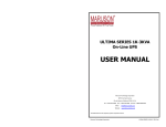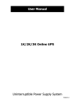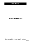
1
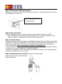
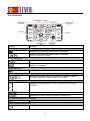
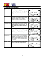
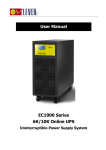
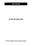
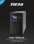
User Manual EC1000 Series 1K/2K/3K Online UPS Uninterruptible Power Supply System Table of Contents 1. Important Safety Warning ................................................................................... 2 1-1. Transportation ........................................................................................................................... 2 1-2. Preparation ................................................................................................................................ 2 1-3. Installation ................................................................................................................................ 2 1-4. Operation .................................................................................................................................. 2 1-5. Maintenance, service and faults................................................................................................ 3 2. Installation and setup .......................................................................................... 3 2-1. Rear panel view ........................................................................................................................ 3 2-2. Setup the UPS ........................................................................................................................... 5 3. Operations ............................................................................................................ 7 3-1. Button operation ....................................................................................................................... 7 3-2. LCD Panel ................................................................................................................................ 8 3-3. Audible Alarm........................................................................................................................... 9 3-4. LCD display wordings index .................................................................................................... 9 3-5. UPS Setting............................................................................................................................. 10 3-6. Operating Mode Description .................................................................................................. 13 3-7. Faults Reference Code ............................................................................................................ 14 3-8. Warning indicator ................................................................................................................... 14 4. Troubleshooting.................................................................................................. 15 5. Storage and Maintenance ................................................................................... 16 6. Specifications ..................................................................................................... 17 1 1. Important Safety Warning Please comply with all warnings and operating instructions in this manual strictly. Save this manual properly and read carefully the following instructions before installing the unit. Do not operate this unit before reading through all safety information and operating instructions carefully 1-1. Transportation Please transport the UPS system only in the original package to protect against shock and impact. 1-2. Preparation Condensation may occur if the UPS system is moved directly from cold to warm environment. The UPS system must be absolutely dry before being installed. Please allow at least two hours for the UPS system to acclimate the environment. Do not install the UPS system near water or in moist environments. Do not install the UPS system where it would be exposed to direct sunlight or near heater. Do not block ventilation holes in the UPS housing. 1-3. Installation Do not connect appliances or devices which would overload the UPS system (e.g. laser printers) to the UPS output sockets. Place cables in such a way that no one can step on or trip over them. Do not connect domestic appliances such as hair dryers to UPS output sockets. The UPS can be operated by any individuals with no previous experience. Connect the UPS system only to an earthed shockproof outlet which must be easily accessible and close to the UPS system. Please use only VDE-tested, CE-marked mains cable (e.g. the mains cable of your computer) to connect the UPS system to the building wiring outlet (shockproof outlet). Please use only VDE-tested, CE-marked power cables to connect the loads to the UPS system. When installing the equipment, it should ensure that the sum of the leakage current of the UPS and the connected devices does not exceed 3.5mA. 1-4. Operation Do not disconnect the mains cable on the UPS system or the building wiring outlet (shockproof socket outlet) during operations since this would cancel the protective earthing of the UPS system and of all connected loads. The UPS system features its own, internal current source (batteries). The UPS output sockets or output terminals block may be electrically live even if the UPS system is not connected to the building wiring outlet. In order to fully disconnect the UPS system, first press the OFF/Enter button to disconnect the mains. Prevent no fluids or other foreign objects from inside of the UPS system. 2 1-5. Maintenance, service and faults The UPS system operates with hazardous voltages. Repairs may be carried out only by qualified maintenance personnel. Caution - risk of electric shock. Even after the unit is disconnected from the mains (building wiring outlet), components inside the UPS system are still connected to the battery and electrically live and dangerous. Before carrying out any kind of service and/or maintenance, disconnect the batteries and verify that no current is present and no hazardous voltage exists in the terminals of high capability capacitor such as BUS-capacitors. Only persons are adequately familiar with batteries and with the required precautionary measures may replace batteries and supervise operations. Unauthorized persons must be kept well away from the batteries. Caution - risk of electric shock. The battery circuit is not isolated from the input voltage. Hazardous voltages may occur between the battery terminals and the ground. Before touching, please verify that no voltage is present! Batteries may cause electric shock and have a high short-circuit current. Please take the precautionary measures specified below and any other measures necessary when working with batteries: -remove wristwatches, rings and other metal objects -use only tools with insulated grips and handles. When changing batteries, install the same number and same type of batteries. Do not attempt to dispose of batteries by burning them. This could cause battery explosion. Do not open or destroy batteries. Escaping electrolyte can cause injury to the skin and eyes. It may be toxic. Please replace the fuse only with the same type and amperage in order to avoid fire hazards. Do not dismantle the UPS system. 2. Installation and setup NOTE: Before installation, please inspect the unit. Be sure that nothing inside the package is damaged. Please keep the original package in a safe place for future use. NOTE: There are two different types of online UPS: standard and long-run models. Please refer to the following model table. Model 1K 2K 3K Type Model 1K-SC 2K-SC 3K-SC Standard 2-1. Rear panel view 1K(L) TOWER 3 Type Long-run IEC Type Schuko Type India Type Africa Type NEMA Type Africa Type NEMA Type AU Type 2K(L) TOWER IEC Type Schuko Type India Type Schuko Type India Type AU Type 3K(L) TOWER IEC Type 1. 2. 3. 4. 5. 6. 7. Africa Type Programmable outlets: connect to non-critical loads. Output receptacles: connect to mission-critical loads. AC input Input circuit breaker Network/Fax/Modem surge protection Emergency power off function connector (EPO) USB communication port 8. RS-232 communication port 9. SNMP intelligent slot 10. External battery connection (only available for L model) 11. Output terminal 12. Output circuit breaker 13. Input terminal 4 NEMA Type AU Type 2-2. Setup the UPS Step 1: UPS input connection Plug the UPS into a two-pole, three-wire, grounded receptacle only. Avoid using extension cords. For 200/208/220/230/240VAC models: The power cord is supplied in the UPS package. For 100/110/115/120/127VAC models: The power cord is attached to the UPS. The input plug is a NEMA 5-15P for 1K, 1K-SC models, NEMA 5-20P for 2K and 2K-SC models. Note: For Low voltage models: Check if the site wiring fault indicator lights up in LCD panel. It will be illuminated when the UPS is plugged into an improperly wired utility power outlet (Refer to Troubleshooting section). Please also install a circuit breaker (40A) between the mains and AC input in 3K model for safety operation. Step 2: UPS output connection For socket-type outputs, there two kinds of outputs: programmable outlets and general outlets. Please connect non-critical devices to the programmable outlets and critical devices to the general outlets. During power failure, you may extend the backup time to critical devices by setting shorter backup time for non-critical devices. For terminal-type input or outputs, please follow below steps for the wiring configuration: a) Remove the small cover of the terminal block b) Suggest using AWG14 or 2.1mm2 power cords. Suggest using AWG12-10 or 3.3mm2-5.3mm2 power cords for NEMA type. c) Upon completion of the wiring configuration, please check whether the wires are securely affixed. d) Put the small cover back to the rear panel. Step 3: Communication connection Communication port: USB port RS-232 port Intelligent slot To allow for unattended UPS shutdown/start-up and status monitoring, connect the communication cable one end to the USB/RS-232 port and the other to the communication port of your PC. With the monitoring software installed, you can schedule UPS shutdown/start-up and monitor UPS status through PC. The UPS is equipped with intelligent slot perfect for either SNMP or AS400 card. When installing either SNMP or AS400 card in the UPS, it will provide advanced communication and monitoring options. PS. USB port and RS-232 port can’t work at the same time. Step 4: Network connection Network/Fax/Phone surge port Connect a single modem/phone/fax line into surge-protected “IN” outlet on the back panel of the UPS unit. Connect from “OUT” outlet to the equipment with another modem/fax/phone line cable. 5 Step 5: Disable and enable EPO function Keep the pin 1 and pin 2 closed for UPS normal operation. To activate EPO function, cut the wire between pin 1 and pin 2. It’s in closed status for UPS normal operation. Step 6: Turn on the UPS Press the ON/Mute button on the front panel for two seconds to power on the UPS. Note: The battery charges fully during the first five hours of normal operation. Do not expect full battery run capability during this initial charge period. Step 7: Install software For optimal computer system protection, install UPS monitoring software to fully configure UPS shutdown. You may insert provided CD into CD-ROM to install the monitoring software. If not, please follow steps below to download and install monitoring software from the internet: 1. Go to the website http://www.power-software-download.com 2. Click ViewPower software icon and then choose your required OS to download the software. 3. Follow the on-screen instructions to install the software. 4. When your computer restarts, the monitoring software will appear as an orange plug icon located in the system tray, near the clock. Step 8: External battery connection (for long-run models only) Follow the right chart to make external battery connection. 6 3. Operations 3-1. Button operation Button Function Turn on the UPS: Press and hold ON/Mute button for at least 2 seconds to turn on the UPS. Mute the alarm: When the UPS is on battery mode, press and hold this button for at least 5 seconds to disable or enable the alarm system. But it’s not applied to the situations when warnings or errors ON/Mute Button occur. Up key: Press this button to display previous selection in UPS setting mode. Switch to UPS self-test mode: Press and hold ON/Mute button for 5 seconds to enter UPS self-testing while in AC mode, ECO mode, or converter mode. Turn off the UPS: Press and hold this button at least 2 seconds to turn off the UPS. UPS will be in standby mode under power normal or transfer to Bypass mode if the Bypass enable setting by pressing this OFF/Enter Button button. Confirm selection key: Press this button to confirm selection in UPS setting mode. Switch LCD message: Press this button to change the LCD message for input voltage, input frequency, battery voltage, output voltage and output frequency. It will return back to default display when pausing for 10 seconds. Select Button Setting mode: Press and hold this button for 5 seconds to enter UPS setting mode when UPS is in standby mode or bypass mode. Down key: Press this button to display next selection in UPS setting mode. Switch to bypass mode: When the main power is normal, press ON/Mute + Select ON/Mute and Select buttons simultaneously for 5 seconds. Then UPS Button will enter to bypass mode. This action will be ineffective when the input voltage is out of acceptable range. 7 3-2. LCD Panel Display Function Remaining backup time information Indicates the remaining backup time in pie chart. Indicates the remaining backup time in numbers. H: hours, M: minute, S: second Fault information Indicates that the warning and fault occurs. Indicates the warning and fault codes, and the codes are listed in details in 3-5 section. Mute operation Indicates that the UPS alarm is disabled. Output & Battery voltage information Indicates the output voltage, frequency or battery voltage. Vac: output voltage, Vdc: battery voltage, Hz: frequency Load information Indicates the load level by 0-25%, 26-50%, 51-75%, and 76-100%. Indicates overload. Indicates the load or the UPS output is short circuit. Programmable outlets information Indicates that programmable management outlets are working. Mode operation information Indicates the UPS connects to the mains. 8 Indicates the battery is working. Indicates the bypass circuit is working. Indicates the ECO mode is enabled. Indicates the Inverter circuit is working. Indicates the output is working. Battery information Indicates the Battery level by 0-25%, 26-50%, 51-75%, and 76-100%. Indicates the battery is fault. Indicates low battery level and low battery voltage. Input & Battery voltage information Indicates the input voltage or frequency or battery voltage. Vac: Input voltage, Vdc: battery voltage, Hz: input frequency 3-3. Audible Alarm Battery Mode Low Battery Overload Fault Bypass Mode Sounding every 4 seconds Sounding every second Sounding twice every second Continuously sounding Sounding every 10 seconds 3-4. LCD display wordings index Abbreviation Display content Meaning ENA Enable DIS Disable ESC Escape HLS High loss LLS Low loss BAT Battery CF Converter EP EPO TP Temperature CH Charger 9 FU Bypass frequency unstable EE EEPROM error 3-5. UPS Setting There are three parameters to set up the UPS. Parameter 1 Parameter 1: It’s for program alternatives. There are 10 programs to set up. Refer to below table. Parameter 2 and parameter 3 are the setting options or values for each program. Parameter 2 Parameter 3 01: Output voltage setting Interface Setting Parameter 3: Output voltage For 200/208/220/230/240 VAC models, you may choose the following output voltage: 200: presents output voltage is 200Vac 208: presents output voltage is 208Vac 220: presents output voltage is 220Vac 230: presents output voltage is 230Vac (Default) 240: presents output voltage is 240Vac For 100/110/150/120/127 VAC models, you may choose the following output voltage: 100: presents output voltage is 100Vac 110: presents output voltage is 110Vac 115: presents output voltage is 115Vac 120: presents output voltage is 120Vac (Default) 127: presents output voltage is 127Vac 02: Frequency Converter enable/disable Interface Setting Parameter 2 & 3: Enable or disable converter mode. You may choose the following two options: CF ENA: converter mode enable CF DIS: converter mode disable (Default) 10 03: Output frequency setting Interface Setting Parameter 2 & 3: Output frequency setting. You may set the initial frequency on battery mode: BAT 50: presents output frequency is 50Hz BAT 60: presents output frequency is 60Hz If converter mode is enabled, you may choose the following output frequency: CF 50: presents output frequency is 50Hz CF 60: presents output frequency is 60Hz 04: ECO enable/disable Interface Setting Parameter 3: Enable or disable ECO function. You may choose the following two options: ENA: ECO mode enable DIS: ECO mode disable (Default) 05: ECO voltage range setting Interface Setting Parameter 2 & 3: Set the acceptable high voltage point and low voltage point for ECO mode by pressing Down key or Up key. HLS: High loss voltage in ECO mode in parameter 2. For 200/208/220/230/240 VAC models, the setting range in parameter 3 is from +7V to +24V of the nominal voltage. (Default: +12V) For 100/110/115/120/127 VAC models, the setting range in parameter 3 is from +3V to +12V of the nominal voltage. (Default: +6V) LLS: Low loss voltage in ECO mode in parameter 2. For 200/208/220/230/240 VAC models, the setting range in parameter 3 is from -7V to -24V of the nominal voltage. (Default: -12V) For 100/110/115/120/127 VAC models, the setting voltage in parameter 3 is from -3V to -12V of the nominal voltage. (Default: -6V) 06: Bypass enable/disable when UPS is off Interface Setting Parameter 3: Enable or disable Bypass function. You may choose the following two options: ENA: Bypass enable DIS: Bypass disable (Default) 11 07: Bypass voltage range setting Interface Setting Parameter 2 & 3: Set the acceptable high voltage point and acceptable low voltage point for Bypass mode by pressing the Down key or Up key. HLS: Bypass high voltage point For 200/208/220/230/240 VAC models: 230-264: setting the high voltage point in parameter 3 from 230Vac to 264Vac. (Default: 264Vac) For 100/110/115/120/127 VAC models: 120-140: setting the high voltage point in parameter 3 from 120Vac to 140Vac(Default: 132Vac) LLS: Bypass low voltage point For 200/208/220/230/240 VAC models: 170-220: setting the low voltage point in parameter 3 from 170Vac to 220Vac (Default: 170Vac) For 100/110/115/120/127 VAC models: 85-115: setting the low voltage point in parameter 3 from 85Vac to 115Vac. (Default: 85Vac) 08: Programmable outlets enable/disable Interface Setting Parameter 3: Enable or disable programmable outlets. ENA: Programmable outlets enable DIS: Programmable outlets disable (Default) 09: Programmable outlets setting Interface Setting Parameter 3: Set up backup time limits for programmable outlets. 0-999: setting the backup time limits in minutes from 0-999 for programmable outlets which connect to non-critical devices on battery mode. (Default: 999) 10: Autonomy limitation setting Interface Setting Parameter 3: Set up backup time on battery mode for general outlets. 0-999: setting the backup time in minutes from 0-999 for general outlets on battery mode. 0: When setting as “0”, the backup time will be only 10 seconds. 999: When setting as “999”, the backup time setting will be disabled. (Default) 00: Exit setting 12 3-6. Operating Mode Description Operating mode Description LCD display Online mode When the input voltage is within acceptable range, UPS will provide pure and stable AC power to output. The UPS will also charge the battery at online mode. ECO mode Energy saving mode: When the input voltage is within voltage regulation range, UPS will bypass voltage to output for energy saving. Frequency Converter mode When input frequency is within 40 Hz to 70 Hz, the UPS can be set at a constant output frequency, 50 Hz or 60 Hz. The UPS will still charge battery under this mode. Battery mode When the input voltage is beyond the acceptable range or power failure and alarm is sounding every 4 second, UPS will backup power from battery. Bypass mode When input voltage is within acceptable range but UPS is overload, UPS will enter bypass mode or bypass mode can be set by front panel. Alarm is sounding every 10 second. Standby mode UPS is powered off and no output supply power, but still can charge batteries. 13 3-7. Faults Reference Code Fault event Fault code Bus start fail 01 Bus over 02 Bus under 03 Bus unbalance 04 Bus fault 05 Inverter soft start fail 11 Inverter voltage high 12 3-8. Warning indicator Warning Icon x x x x x x x Fault event Inverter voltage Low Inverter output short Battery voltage too high Battery voltage too low Over temperature Over load Icon (flashing) Fault code 13 14 27 28 41 43 Icon x x Alarm Low Battery Sounding every second Overload Sounding twice every second Battery is not connected Sounding every second Sounding every second Over Charge Sounding every second Site wiring fault EPO enable Sounding every second Over temperature Sounding every second Charger failure Sounding every second Battery fault Sounding every second Out of bypass voltage range Sounding every second Bypass frequency unstable Sounding every second EEPROM error Sounding every second NOTE: “Site Wiring Fault” function can be enabled/disabled via software. Please check software manual for the details. 14 4. Troubleshooting If the UPS system does not operate correctly, please solve the problem by using the table below. Symptom Possible cause Remedy No indication and alarm even The AC input power is not Check if input power cord though the mains is normal. connected well. firmly connected to the mains. The AC input is connected to Plug AC input power cord the UPS output. to AC input correctly. The icon and the warning code flashing on LCD display and alarm is sounding every second. EPO function is activated. Set the circuit in closed position to disable EPO function. Line and neutral conductors of Rotate mains power socket The icon and flashing UPS input are reversed. by 180° and then connect on LCD display and alarm is to UPS system. sounding every second. The external or internal Check if all batteries are The icon and battery is incorrectly connected well. flashing on LCD display and connected. alarm is sounding every second. Fault code is shown as 27 and Battery voltage is too high or the charger is fault. the icon is lighting on LCD display and alarm is continuously sounding. Fault code is shown as 28 and Battery voltage is too low or the charger is fault. the icon is lighting on LCD display and alarm is continuously sounding. UPS is overload The icon and is flashing on LCD display and UPS is overloaded. Devices alarm is sounding twice every connected to the UPS are fed second. directly by the electrical network via the Bypass. After repetitive overloads, the UPS is locked in the Bypass mode. Connected devices are fed directly by the mains. Fault code is shown as 43 and The UPS shut down automatically because of The icon is lighting overload at the UPS output. on LCD display and alarm is continuously sounding. 15 Contact your dealer. Contact your dealer. Remove excess loads from UPS output. Remove excess loads from UPS output. Remove excess loads from UPS output first. Then shut down the UPS and restart it. Remove excess loads from UPS output and restart it. Symptom Possible cause Fault code is shown as 14 and The UPS shut down the icon is lighting on automatically because short circuit occurs on the UPS LCD display and alarm is output. continuously sounding. Remedy Check output wiring and if connected devices are in short circuit status. Fault code is shown as 01, 02, 03, 04, 05, 11, 12, 13 and 41 on LCD display and alarm is continuously sounding. A UPS internal fault has Contact your dealer occurred. There are two possible results: 1. The load is still supplied, but directly from AC power via bypass. 2. The load is no longer supplied by power. Battery backup time is shorter Batteries are not fully charged Charge the batteries for at than nominal value least 5 hours and then check capacity. If the problem still persists, consult your dealer. Batteries defect Contact your dealer to replace the battery. Fault code is shown as 05 on A UPS internal fault has Consult your dealer. If the LCD display. At the same time, occurred and BUS is short UPS power is on again alarm is continuously circuit before repair, the DC/DC sounding and output is cut off mosfet will damage. 5. Storage and Maintenance Operation The UPS system contains no user-serviceable parts. If the battery service life (3~5 years at 25°C ambient temperature) has been exceeded, the batteries must be replaced. In this case, please contact your dealer. Be sure to deliver the spent battery to a recycling facility or ship it to your dealer in the replacement battery packing material. Storage Before storing, charge the UPS 5 hours. Store the UPS covered and upright in a cool, dry location. During storage, recharge the battery in accordance with the following table: Storage Temperature Recharge Frequency Charging Duration -25°C - 40°C Every 3 months 1-2 hours 40°C - 45°C Every 2 months 1-2 hours 16 6. Specifications CAPACITY* INPUT Low Line Transfer Voltage Range Low Line Comeback High Line Transfer High Line Comeback Frequency Range Phase Power Factor OUTPUT Output voltage AC Voltage Regulation Frequency Range (Synchronized Range) Frequency Range (Batt. Mode) 1000 VA / 800 W 2000 VA / 1600 W 3000 VA / 2400 W 160VAC/140VAC/120VAC/110VAC ± 5 % or 80VAC/70VAC/60VAC/55VAC ± 5 % ( based on load percentage 100% - 80 % / 80 % - 70 % / 70 - 60 % / 60 % - 0) 168 VAC ± 5 % or 84 VAC ± 5 % 300 VAC ± 5 % or 150 VAC ± 5 % 290 VAC ± 5 % or 145 VAC ± 5 % 40Hz ~ 70 Hz Single phase with ground ≧ 0.99 @ Nominal voltage (full load) 200/208/220/230/240VAC or 100/110/115/120/127 VAC ± 1% (Batt. Mode) 47 ~ 53 Hz or 57 ~ 63 Hz 50 Hz ± 0.25 Hz or 60Hz ± 0.3 Hz 100%~110%: audible warning 110%-130%: UPS shuts down in 30 seconds at battery mode or transfers to bypass Overload mode when the utility is normal. >130%: UPS shuts down immediately at battery mode or transfer to bypass mode when the utility is normal. Current Crest Ratio 3:1 ≦ 2 % THD (Linear Load) Harmonic Distortion ≦ 4 % THD (Non-linear Load) Zero Transfer AC Mode to Batt. Mode Time Inverter to Bypass 4 ms (Typical) Waveform (Batt. Mode) Pure Sinewave EFFICIENCY AC Mode ~ 87% ~ 90% Battery Mode ~ 83% ~ 87% BATTERY Battery Type 12 V / 7 AH 12 V / 7 AH 12 V / 9 AH Numbers 3 6 6 Standard Recharge Time 4 hours recover to 90% capacity (Typical) Model Charging Current 1.0 A(max.) Charging Voltage 41.0 VDC ± 1% 82.1 VDC ±1% Battery Type & Depending on the capacity of external batteries Long-run Numbers Model Charging Current 4.0 A or 8.0 A(max.) Charging Voltage 41.0 VDC ± 1% 82.1 VDC ±1% PHYSICAL Dimension, D X W X H 397 X 145 X 220 (mm) 421 X 190 X 318 (mm) Net Weight (kgs) 13 7 26 13 28 13 ENVIRONMENT Operation Humidity 20-90 % RH @ 0- 40°C (non-condensing) Noise Level Less than 50dBA @ 1 Meter MANAGEMENT Smart RS-232 or USB Supports Windows® 2000/2003/XP/Vista/2008/7, Linux, Unix and MAC Optional SNMP Power management from SNMP manager and web browser * Derate capacity to 60% of capacity in Frequency converter mode and to 80% when the output voltage is adjusted to 100VAC, 200VAC or 208VAC. ** Product specifications are subject to change without further notice. 17 Manuale utente Serie EC1000 1K/2K/3K UPS Online Sistema UPS (Uninterruptible Power Supply) Indice 1. Avviso importante per la sicurezza .................................................................... 20 1-1. Trasporto ......................................................................................................... 20 1-2. Preparazione .................................................................................................... 20 1-3. Installazione ..................................................................................................... 20 1-4. Funzionamento................................................................................................. 20 1-5. Manutenzione, assistenza e guasti ..................................................................... 21 2. Installazione e setup .......................................................................................... 21 2-1. Vista pannello posteriore ................................................................................... 21 2-2. Setup dell'UPS .................................................................................................. 23 3. Funzionamento ................................................................................................... 25 3-1. Funzioni del pulsante ........................................................................................ 25 3-2. Pannello LCD .................................................................................................... 25 3-3. Allarme sonoro ................................................................................................. 27 3-4. Sigle display LCD .............................................................................................. 27 3-5. Impostazione UPS ............................................................................................ 28 3-6. Descrizione modalità operativa .......................................................................... 31 3-7. Codici di riferimento guasti ................................................................................ 32 3-8. Indicatore avviso .............................................................................................. 32 4. Risoluzione dei problemi .................................................................................... 33 5. Stoccaggio e manutenzione ............................................................................... 34 6. Specifiche ........................................................................................................... 36 19 1. Avviso importante per la sicurezza Vi preghiamo di rispettare completamente tutti gli avvisi e le istruzioni operative di questo manuale. Conservare correttamente questo manuale e leggere attentamente le istruzioni seguenti prima di installare l'unità. Non utilizzare questa unità prima di aver letto attentamente tutte le informazioni operative e di sicurezza 1-1. Trasporto Vi preghiamo di trasportare il sistema UPS solo nell'imballo originale per proteggerlo da colpi ed urti. 1-2. Preparazione Se il sistema UPS viene spostato direttamente da un ambiente freddo ad uno caldo si può creare della condensa. Il sistema UPS deve assolutamente essere asciutto prima di essere installato. Attendere almeno due ore per consentire l'acclimatazione del sistema UPS nel nuovo ambiente. Non installare il sistema UPS vicino all'acqua o in ambienti umidi. Non installare il sistema UPS dove sarebbe esposto a luce solare diretta o vicino ad un calorifero. Non bloccare i fori di ventilazione nell'alloggiamento dell'UPS. 1-3. Installazione Non collegare apparecchiature o dispositivi che sovraccaricherebbero il sistema UPS (ad esempio stampanti laser) alle prese di output dell'UPS. Posizionare i cavi in modo che nessuno possa calpestarli o inciampare su di essi. Non collegare apparecchiature domestiche come asciugacapelli alle prese di output dell'UPS. L'UPS può essere utilizzato da qualsiasi persona anche priva di esperienza. Collegare il sistema UPS solo ad una presa con messa a terra e munita di protezione da scosse, che deve essere facilmente accessibile e vicina al sistema UPS. Usare solo cavi di rete testati VDE e marchiati CE (ad esempio i cavi di rete del vostro computer) per collegare il sistema UPS alla presa di rete dell'edificio (presa munita di protezione da scosse). Usare solo cavi elettrici testati VDE e marcati CE per collegare i carichi al sistema UPS. Quando si installa l'apparecchiatura, la somma della corrente di dispersione dell'UPS e dei dispositivi connessi non deve superare 3,5mA. 1-4. Funzionamento Non scollegare il cavo di rete sul sistema UPS o la presa elettrica dell'edificio (presa munita di protezione da scosse) durante l'utilizzo in quanto questo annullerebbe la messa a terra protettiva del sistema UPS e di tutti i carichi connessi. Il sistema UPS è munito di una fonte di corrente elettrica interna (batterie). Le prese o le morsettiere di output dell'UPS possono essere sotto tensione anche se il sistema UPS non è collegato alla presa elettrica dell'edificio. Per scollegare completamente il sistema UPS, per prima cosa premere il pulsante OFF/Enter per scollegare la rete. 20 Evitare che fluidi ed altri corpi estranei entrino all'interno del sistema UPS. 1-5. Manutenzione, assistenza e guasti Il sistema UPS funziona con tensioni pericolose. Le riparazioni possono essere effettuate solo da personale di manutenzione qualificato. Attenzione - rischio di scossa elettrica. Anche quando l'unità è scollegata dalla rete elettrica (presa di rete dell'edificio), i componenti all'interno del sistema UPS sono ancora collegati alla batteria, sono sotto tensione e sono quindi pericolosi. Prima di effettuare qualsiasi tipo di servizio e/o manutenzione, scollegare le batterie e verificare che non sia presente corrente e tensione pericolosa nei terminali dei condensatori ad alta capacità come i condensatori BUS. Solo persone che hanno un'adeguata familiarità con le batterie e con le misure precauzionali necessarie possono sostituire le batterie e supervisionare le operazioni. Le persone non autorizzate non devono avvicinarsi alle batterie. Attenzione - rischio di scossa elettrica. Il circuito della batteria non è isolato dalla tensione di ingresso. Si possono verificare tensioni pericolose tra i terminali della batteria e la terra. Prima di intervenire, verificare che non siano presenti tensioni! Le batterie possono causare scosse elettriche ed avere un'elevata corrente di cortocircuito. Vi preghiamo di prendere le misure precauzionali specificate sotto e qualsiasi altra misura necessaria quando si lavora con le batterie: -rimuovere orologi da polso, anelli ed altri oggetti metallici -usare solo utensili con impugnature isolate. Quando si sostituiscono le batterie, installare lo stesso numero e tipo di batterie. Non tentare di smaltire le batterie bruciandole. Questo potrebbe causare l'esplosione della batteria. Non aprire o distruggere le batterie. La fuoriuscita di elettrolito può causare lesione alla pelle ed agli occhi. Può essere tossico. Quando si sostituisce un fusibile, usarne uno dello stesso tipo e con lo stesso amperaggio, per evitare pericoli di incendio. Non smantellare il sistema UPS. 2. Installazione e setup NOTA: Prima dell'installazione, ispezionare l'unità. Accertarsi che non risulti danneggiato nulla all'interno dell'imballaggio. Conservare l'imballaggio originale in un luogo sicuro per uso futuro. NOTA: Esistono due tipi diversi di UPS online: standard ed a lunga autonomia. Fare riferimento alla seguente tabella dei modelli. Modello 1K 2K 3K Tipo Standard 2-1. Vista pannello posteriore 1K(L) TOWER 21 Modello 1K-SC 2K-SC 3K-SC Tipo Lunga autonomia Tipo IEC Tipo Schuko Tipo India Tipo Africa Tipo NEMA Tipo Africa Tipo NEMA Tipo AU 2K(L) TOWER Tipo IEC Tipo Schuko Tipo India Tipo Schuko Tipo India Tipo AU 3K(L) TOWER Tipo IEC 1. 2. 3. 4. 5. 6. 7. Tipo Africa Tipo NEMA Prese programmabili: connessione a carichi non critici. Prese di output: connessione a carichi critici. Ingresso AC Interruttore circuito input Protezione sovratensione rete/fax/modem Connettore funzione spegnimento di emergenza (EPO) Porta comunicazione USB 8. Porta comunicazione RS-232 9. Slot intelligente SNMP 10. Connessione batteria esterna (disponibile solo per modello L) 11. Terminale di output 12. Interruttore circuito output 13. Terminale input 22 Tipo AU 2-2. Setup dell'UPS Passaggio 1: Connessione input UPS Collegare l'UPS solo ad una presa a due poli, tre fili, con messa a terra. Evitare di usare prolunghe. Per modelli 200/208/220/230/240VAC: Il cavo elettrico è fornito nell'imballaggio dell'UPS. Per modelli 100/110/115/120/127VAC: Il cavo elettrico è collegato all'UPS. La presa di input è di tipo NEMA 5-15P per i modelli 1K, 1K-SC, di tipo NEMA 5-20P per i modelli 2K e 2K-SC. Nota: Per modelli a bassa tensione: Verificare se nel pannello LCD si accende l'indicatore di guasto del cablaggio. Si illumina quando l'UPS è collegato in una presa di rete con cablaggio errato (Fare riferimento alla sezione Risoluzione dei problemi). Installare anche un interruttore (40A) tra la rete e l'input AC nel modello 3K per un utilizzo sicuro. Passaggio 2: Connessione output UPS Esistono due tipi di prese di output: programmabili e standard. Collegare i dispositivi non critici alle prese programmabili e i dispositivi critici alle prese standard. In caso di mancanza di energia elettrica, è possibile estendere i tempi di backup per i dispositivi critici impostando un tempo di backup più breve per i dispositivi non critici. Per i terminali di input o output, seguire i passi seguenti per la configurazione del cablaggio: a) Rimuovere il coperchietto della morsettiera b) Suggeriamo l'utilizzo di cavi elettrici AWG14 o da 2,1 mm2. Suggeriamo l'utilizzo di cavi elettrici AWG12-10 o da 3,3 mm2-5.3mm2 per il tipo NEMA. c) Dopo aver completato la configurazione del cablaggio, verificare se i cavi sono fissati in modo sicuro. d) Rimettere il coperchietto sul pannello posteriore. Passaggio 3: Connessione comunicazione Porta di comunicazione: Porta USB Porta RS-232 Slot intelligente Per consentire l'arresto/avvio automatico ed il monitoraggio dello stato dell'UPS, collegare il cavo di comunicazione da una parte alla porta USB/RS-232 e dell'altra alla porta di comunicazione del proprio PC. Con il software di monitoraggio installato, è possibile programmare l'arresto/avvio dell'UPS e monitorare lo stato dell'UPS tramite PC. L'UPS è munito di slot intelligente, perfetto per scheda SNMP o AS400. Quando si installa la scheda SNMP o AS400 nell'UPS, questa fornisce opzioni avanzate di comunicazione e monitoraggio. PS. La porta USB e la porta RS-232 non possono funzionare contemporaneamente. Passaggio 4: Connessione alla rete Porta sovratensione rete/fax/telefono Collegare un'unica linea modem/telefono/fax nella presa protetta contro sovratensioni “IN” sul 23 pannello posteriore dell'unità UPS. Effettuare il collegamento dalla presa “OUT” all'apparecchiatura con un altro cavo di linea modem/fax/telefono. Passaggio 5: Disabilitazione ed abilitazione della funzione EPO Tenere il pin 1 ed il pin 2 chiusi per il funzionamento standard dell'UPS. Per attivare la funzione EPO, tagliare il filo tra il pin 1 ed il pin 2. È in stato chiuso per il funzionamento normale dell'UPS. Passaggio 6: Accendere l'UPS Premere il pulsante ON/Mute sul pannello frontale per due secondi per accendere l'UPS. Nota: La batteria si carica completamente nel corso delle prime cinque ore di funzionamento normale. Non aspettarsi una capacità operativa di batteria completamente carica durante questo periodo iniziale di carica. Passaggio 7: Installazione del software Per una protezione ottimale, installare il software di monitoraggio dell'UPS per configurare completamente l'arresto dell'UPS. Inserire il CD in dotazione nell'unità CD-ROM per installare il software di monitoraggio. Altrimenti, seguire i passi seguenti per scaricare da internet ed installare il software di monitoraggio: 1. Andare al sito http://www.power-software-download.com 2. Cliccare sull'icona del software ViewPower e quindi scegliere il sistema operativo per scaricare il software. 3. Seguire le istruzioni sullo schermo per installare il software. 4. Quando il computer si riavvia, il software di monitoraggio apparirà come icona arancione nella barra di sistema, vicino all'orologio. Passaggio 8: Connessione batteria esterna (solo per modelli a lunga autonomia) Seguire la figura a destra per effettuare la connessione della batteria esterna. 24 3. Funzionamento 3-1. Funzioni del pulsante Pulsante Funzione Accende l'UPS: Premere il pulsante ON/Mute per almeno 2 secondi per accendere l'UPS. Disattiva l'allarme: Quando l'UPS è in modalità batteria, tenere premuto per almeno 5 secondi per disabilitare o abilitare il sistema di allarme. Questo non vale per situazioni in cui si verificano avvisi o errori. Pulsante ON/Mute Tasto Up: Premere questo pulsante per visualizzare la selezione precedente nella modalità impostazione UPS. Passare alla modalità auto test UPS: Tenere premuto il pulsante ON/Mute per 5 secondi per entrare nell'auto-test UPS durante la modalità AC, ECO, o convertitore. Spegne l'UPS: Tenere premuto questo pulsante almeno 2 secondi per spegnere l'UPS. Premendo questo pulsante l'UPS andrà in modalità standby sotto alimentazione normale o passerà alla modalità Bypass Pulsante OFF/Enter se abilitata. Tasto conferma selezione: Premere questo pulsante per confermare la selezione in modalità impostazione UPS. Cambia il messaggio LCD: Premere questo pulsante per visualizzare i diversi messaggi su display LCD: tensione di input, frequenza di input, tensione batteria, tensione di output e frequenza di output. Ritornerà alla visualizzazione di default in caso di pausa per 10 secondi. Pulsante Modalità impostazione: Tenere premuto questo pulsante per 5 Seleziona secondi per entrare in modalità impostazione UPS quando l'UPS è in modalità standby o bypass. Tasto Down: Premere questo pulsante per visualizzare la selezione successiva in modalità impostazione UPS. Passa alla modalità bypass: Quando l'alimentazione di rete è Pulsante normale, premere contemporaneamente i pulsanti ON/Mute e Select ON/Mute + Select per 5 secondi. L'UPS entrerà in modalità bypass. Questa azione non avrà effetto quando la tensione di input è fuori dal range accettabile. 3-2. Pannello LCD 25 Display Funzione Informazione tempo backup rimanente Indica il tempo di backup rimanente in formato grafico. Indica il tempo di backup rimanente in formato numerico. H: ore, M: minuti, S: secondi Informazioni guasto Indica che si è verificato un avviso ed un guasto. Indica i codici di avviso e di guasto, che sono elencati in dettaglio nella sezione 3-5. Funzionamento in Mute Indica che l'allarme UPS è disabilitato. Informazione tensione output & batteria Indica la tensione di output, la frequenza di output o la tensione della batteria. Vac: tensione di output, Vdc: tensione della batteria, Hz: frequenza Informazione carico Indica il livello del carico: 0-25%, 26-50%, 51-75%, 76-100%. Indica sovraccarico. Indica che il carico o l'output dell'UPS è in cortocircuito. Informazioni sulle prese programmabili Indica che le prese programmabili stanno funzionando. Informazioni modalità operativa Indica che l'UPS è collegato alla rete. Indica che la batteria sta funzionando. Indica che il circuito di bypass sta funzionando. Indica che la modalità ECO è abilitata. Indica che il circuito dell'Inverter sta funzionando. Indica che l'output sta funzionando. Informazioni sulla batteria Indica il livello della batteria: 0-25%, 26-50%, 51-75%, 76-100%. Indica un guasto della batteria. 26 Indica un livello della batteria basso ed una tensione della batteria bassa. Informazione tensione input e batteria Indica la tensione o frequenza di ingresso o la tensione della batteria. Vac: Tensione di input, Vdc: tensione batteria, Hz: frequenza di input 3-3. Allarme sonoro Modalità batteria Low Battery Suona ogni 4 secondi Suona ogni secondo Overload Suona due volte al secondo Guasto Modalità bypass Suona in modo continuo Suona ogni 10 secondi 3-4. Sigle display LCD Sigla Contenuto display Significato ENA Abilita DIS Disabilita ESC Uscita HLS Perdita elevata LLS Perdita bassa BAT Batteria CF Convertitore EP EPO TP Temperatura CH Caricatore FU Frequenza Bypass instabile EE Errore EEPROM 27 3-5. Impostazione UPS Per l'impostazione dell'UPS sono a disposizione tre parametri. Parametro 1 Parametro 1: Relativo alla scelta del programma. È possibile impostare 10 programmi. Fare riferimento alla tabella sotto. Il parametro 2 ed il parametro 3 impostano le opzioni ed i valori per ogni programma. Parametro 2 Parametro 3 01: Impostazione tensione di output Interfaccia Impostazione Parametro 3: Tensione di output Per i modelli 200/208/220/230/240 VAC, è possibile scegliere la seguente tensione di output: 200: tensione di output di 200Vac 208: tensione di output di 208Vac 220: tensione di output di 220Vac 230: tensione di output di 230Vac (Default) 240: tensione di output di 240Vac Per i modelli 100/110/150/120/127 VAC, è possibile scegliere la seguente tensione di output: 100: tensione di output di 100Vac 110: tensione di output di 110Vac 115: tensione di output di 115Vac 120: tensione di output di 120Vac (Default) 127: tensione di output di 127Vac 02: Abilita/disabilita convertitore frequenza Interfaccia Impostazione Parametro 2 & 3: Abilita o disabilita la modalità convertitore. È possibile scegliere le seguenti due opzioni: CF ENA: abilita modalità convertitore CF DIS: disabilita modalità convertitore (Default) 28 03: Impostazione frequenza di output Interfaccia Impostazione Parametro 2 & 3: Impostazione frequenza di output. È possibile impostare la frequenza iniziale in modalità batteria: BAT 50: frequenza di output 50Hz BAT 60: frequenza di output 60Hz Se la modalità convertitore è abilitata, è possibile scegliere la seguente frequenza di output: CF 50: frequenza di output 50Hz CF 60: frequenza di output 60Hz 04: Abilita/disabilita ECO Interfaccia Impostazione Parametro 3: Abilita o disabilita la funzione ECO. È possibile scegliere le seguenti due opzioni: ENA: Abilita modalità ECO DIS: Disabilita modalità ECO (Default) 05: Impostazione range tensione ECO Interfaccia Impostazione Parametro 2 & 3: Imposta il punto di tensione alto e basso accettabile per la modalità ECO premendo il tasto Down o Up. HLS: Perdita tensione alta in modalità ECO nel parametro 2. Per i modelli 200/208/220/230/240 VAC, il range di impostazione nel parametro 3 è da +7V a +24V della tensione nominale. (Default: +12V) Per i modelli 100/110/115/120/127 VAC, il range di impostazione nel parametro 3 è da +3V a +12V della tensione nominale. (Default: +6V) LLS: Perdita tensione bassa in modalità ECO nel parametro 2. Per i modelli 200/208/220/230/240 VAC, il range di impostazione nel parametro 3 è da -7V a -24V della tensione nominale. (Default: -12V) Per i modelli 100/110/115/120/127 VAC, il range di tensione nel parametro 3 è da -3V a -12V della tensione nominale. (Default: -6V) 29 06: Abilita/disabilita bypass quando l'UPS è spento Interfaccia Impostazione Parametro 3: Abilita o disabilita la funzione Bypass. È possibile scegliere le seguenti due opzioni: ENA: Abilita Bypass DIS: Disabilita Bypass (Default) 07: Impostazione range tensione Bypass Interfaccia Impostazione Parametro 2 & 3: Imposta il punto di tensione alto e basso accettabile per la modalità Bypass premendo il tasto Down o Up. HLS: Punto tensione alto Bypass Per modelli 200/208/220/230/240 VAC: 230-264: impostazione il punto di tensione alto nel parametro 3 da 230Vac a 264Vac. (Default: 264Vac) Per modelli 100/110/115/120/127 VAC: 120-140: impostazione il punto di tensione alto nel parametro 3 da 120Vac a 140Vac(Default: 132Vac) LLS: Punto tensione basso Bypass Per modelli 200/208/220/230/240 VAC: 170-220: impostazione il punto di tensione basso nel parametro 3 da 170Vac a 220Vac (Default: 170Vac) Per modelli 100/110/115/120/127 VAC: 85-115: impostazione il punto di tensione basso nel parametro 3 da 85Vac a 115Vac (Default: Default: 85Vac) 08: Abilita/disabilita prese programmabili Interfaccia Impostazione Parametro 3: Abilita o disabilita le prese programmabili. ENA: Abilita prese programmabili DIS: Disabilita le prese programmabili (Default) 09: Impostazione prese programmabili Interfaccia Impostazione Parametro 3: Imposta limiti tempo backup per prese programmabili. 0-999: impostazione limiti tempo backup in minuti da 0-999 per prese programmabili che connettono dispositivi non critici in modalità batteria. (Default: 999) 30 10: Impostazione limitazione autonomia Interfaccia Impostazione Parametro 3: Impostazione tempo backup in modalità batteria per prese standard. 0-999: impostazione del tempo di backup da 0 a 999 minuti per prese standard in modalità batteria. 0: Quando è impostato a “0”, il tempo di backup sarà solo 10 secondi. 999: Quando è impostato a “999”, l'impostazione del tempo di backup sarà disabilitata. (Default) 00: Esci dalle impostazioni 3-6. Descrizione modalità operativa Modalità Descrizione operativa Modalità online Quando la tensione di input è all'interno di un range accettabile, l'UPS fornirà alimentazione AC pura e stabile all'output. L'UPS inoltre caricherà la batteria in modalità online. Modalità ECO Modalità risparmio energetico: Quando la tensione di input è all'interno del range di regolazione della tensione, l'UPS bypasserà la tensione all'output per risparmiare energia. Modalità convertitore frequenza Quando la frequenza di input è tra 40 Hz e 70 Hz, l'UPS può essere impostato ad una frequenza di output costante, 50 Hz o 60 Hz. In questo modalità, l'UPS caricherà comunque la batteria. Modalità batteria Quanto la tensione di input è oltre il range accettabile o in caso di mancanza di alimentazione (l'allarme suona ogni 4 secondi), l'UPS fornirà alimentazione di backup dalla batteria. Modalità Bypass Quando la tensione di input è all'interno del range accettabile, ma l'UPS è sovraccarico, l'UPS entrerà in modalità bypass oppure la modalità bypass può essere impostata dal pannello frontale. L'allarme suona ogni 10 secondi. 31 Display LCD Modalità standby L'UPS si spegne e non fornisce alimentazione in output, ma può ancora caricare le batterie. 3-7. Codici di riferimento guasti Evento guasto Codice guasto Icona Evento guasto Guasto avvio Bus 01 x Tensione inverter bassa Bus sopra 02 x Output inverter in corto Tensione batteria troppo alta Bus sotto 03 x Tensione batteria troppo bassa Bus sbilanciato 04 x Bus guasto 05 x Temperatura eccessiva Guasto soft start inverter 11 x Sovraccarico Tensione Inverter alta 12 x Codice guasto Icona 13 x 14 27 28 41 x 43 3-8. Indicatore avviso Avviso Icona (lampeggiante) Allarme Batteria scarica Suona ogni secondo Sovraccarico Suona due volte al secondo Batteria non connessa Suona ogni secondo Suona ogni secondo Sovraccarico Suona ogni secondo Guasto cablaggio sito Abilita EPO Suona ogni secondo Temperatura eccessiva Suona ogni secondo Guasto caricatore Suona ogni secondo Guasto batteria Suona ogni secondo Range tensione fuori bypass Suona ogni secondo Frequenza Bypass instabile Suona ogni secondo Errore EEPROM Suona ogni secondo NOTA: La funzione “Site Wiring Fault” può essere abilitata/disabilitata tramite software. Per maggiori informazioni consultare il manuale del software. 32 4. Risoluzione dei problemi Se il sistema UPS non funziona correttamente, risolvere il problema usando la tabella seguente. Sintomo Possibile causa Rimedio Nessuna indicazione ed allarme L'alimentazione AC in Verificare che il cavo elettrico anche se la rete è normale. ingresso non è collegata in ingresso sia collegato correttamente. saldamente alla rete. L'input AC è collegato Collegare correttamente il all'output UPS. cavo di alimentazione AC in ingresso all'input AC. La funzione EPO è attivata. Impostare il circuito in L'icona ed il codice avviso posizione chiusa per lampeggiano sul display LCD disabilitare la funzione e l'allarme suona ogni secondo. EPO. I conduttori linea e neutro Ruotare la presa di Le icone e lampeggiano dell'input UPS sono alimentazione di rete di sul display LCD e l'allarme suona invertiti. 180° e quindi collegare al una volta al secondo. sistema UPS. La batteria esterna o Verificare se le batterie Le icone e interna è connessa in sono connesse lampeggiano sul display LCD e modo non corretto. correttamente. l'allarme suona una volta al secondo. Il codice guasto visualizzato è 27 e l'icona lampeggia sul display LCD e l'allarme suona in modo continuo. Il codice guasto visualizzato è 28 e l'icona lampeggia sul display LCD e l'allarme suona in modo continuo. L'icona e lampeggiano sul display LCD e l'allarme suona due volte al secondo. La tensione della batteria è Contattare troppo elevata o il rivenditore. caricatore è guasto. il proprio La tensione della batteria è Contattare troppo bassa o il caricatore rivenditore. è guasto. il proprio L'UPS è sovraccarico L'UPS è sovraccarico. I dispositivi connessi all'UPS sono alimentati direttamente dalla rete elettrica tramite Bypass. Dopo sovraccarichi ripetuti, l'UPS si blocca in modalità Bypass. I dispositivi connessi sono alimentati direttamente dalla rete. 33 Rimuovere eccesso dell'UPS. Rimuovere eccesso dell'UPS. i carichi in dall'output i carichi in dall'output Per prima cosa rimuovere i carichi in eccesso dall'output dell'UPS. Quindi spegnere e riaccendere l'UPS. Sintomo Il codice guasto visualizzato è 43 e l'icona lampeggia sul display LCD e l'allarme suona in modo continuo. Il codice guasto visualizzato è 14 e l'icona lampeggia sul display LCD e l'allarme suona in modo continuo. Il codice guasto mostrato è 01, 02, 03, 04, 05, 11, 12, 13 e 41 sul display LCD e l'allarme suona in modo continuo. Possibile causa L'UPS si è spento automaticamente a causa del sovraccarico presso l'output dell'UPS. Rimedio Rimuovere i carichi in eccesso dall'output dell'UPS e riavviarlo. L'UPS si è spento automaticamente a causa di un cortocircuito presso l'output dell'UPS. Controllare il cablaggio in output e se i dispositivi connessi sono in stato di cortocircuito. Si è verificato un guasto interno dell'UPS. Ci sono due possibili risultati: 1. Il carico viene ancora fornito, ma direttamente dall'alimentazione AC tramite bypass. 2. Il carico non viene più fornito dall'alimentazione. Il tempo di backup della batteria è Le batterie non sono inferiore al valore nominale completamente cariche Il codice guasti mostrato sul display LCD è 05. Allo stesso tempo, l'allarme suona in modo continuo e l'output è disabilitato Contattare rivenditore il proprio Caricare le batterie per almeno 5 ore e quindi verificare la capacità. Se il problema persiste, consultare il proprio rivenditore. Difetto delle batterie Contattare il proprio rivenditore per sostituire la batteria. Si è verificato un guasto Contattare il proprio interno dell'UPS ed il BUS è rivenditore. Se in cortocircuito l'alimentazione UPS è nuovamente attiva prima della riparazione, il mosfet DC/DC subirà un danno. 5. Stoccaggio e manutenzione Funzionamento Il sistema UPS non contiene parti che possono essere riparate dall'utente. Se la vita di servizio della batteria (da 3 a 5 anni ad una temperatura ambiente di 25°C) è stata superata, le batterie devono essere sostituite. In questo caso, contattare il proprio rivenditore. Portare la batteria scarica ad un centro per il riciclo o inviarla al proprio rivenditore nel materiale di imballaggio della batteria sostitutiva. 34 Stoccaggio Prima dello stoccaggio, caricare l'UPS per 5 ore. Stoccare l'UPS coperto ed in posizione eretta in un luogo fresco e secco. Durante lo stoccaggio, ricaricare la batteria secondo la seguente tabella: Temperatura di stoccaggio Frequenza di ricarica Durata della ricarica -25°C - 40°C Ogni 3 mesi 1-2 ore 40°C - 45°C Ogni 2 mesi 1-2 ore 35 6. Specifiche CAPACITÀ* INPUT 1000 VA / 800 W 2000 VA / 1600 W 3000 VA / 2400 W Trasferimento linea 160VAC/140VAC/120VAC/110VAC ± 5 % o 80VAC/70VAC/60VAC/55VAC ± 5 % bassa (basato su una percentuale di carico 100% - 80 % / 80 % - 70 % / 70 - 60 % / 60 % - 0) Range Ritorno linea bassa 168 VAC ± 5 % o 84 VAC ± 5 % tensione Trasferimento linea alta 300 VAC ± 5 % o 150 VAC ± 5 % Ritorno linea alta 290 VAC ± 5 % o 145 VAC ± 5 % Gamma di frequenza 40Hz ~ 70 Hz Fase Fase singola con terra ≧ 0,99 a Tensione nominale (carico completo) Fattore potenza OUTPUT Tensione di output 200/208/220/230/240VAC o 100/110/115/120/127 VAC Regolazione tensione AC ± 1% (Modalità batteria) Gamma di frequenza 47 ~ 53 Hz o 57 ~ 63 Hz (Range sincronizzato) Range frequenza (Modalità batteria) Overload Fattore di cresta della corrente Distorsione armonica Da modalità AC a Tempo di modalità batteria trasferi-mento Da inverter a bypass Forma d'onda (Modalità batteria) EFFICIENZA Modalità AC Modalità batteria BATTERIA Tipo di batteria Numeri Modello Tempo di ricarica standard Corrente di carica Tensione di carica Tipo e numero di Modello a batterie lunga Corrente di carica autono-mia Tensione di carica CARATTERISTICHE FISICHE Dimensione, P X L X A Peso netto (kg) AMBIENTE Umidità operativa Livello rumore GESTIONE Smart RS-232 o USB SNMP opzionale 50 Hz ± 0.25 Hz o 60Hz ± 0.3 Hz 100%~110%: avviso acustico 110%-130%: L'UPS si spegne in 30 secondi in modalità batteria o passa alla modalità bypass quando la rete è normale. >130%: L'UPS si spegne immediatamente in modalità batteria o passa alla modalità bypass quando la rete è normale. 3:1 ≦ 2 % THD (Carico lineare) ≦ 4 % THD (Carico non lineare) Zero 4 ms (Tipico) Onda sinusoidale pura ~ 87% ~ 83% ~ 90% ~ 87% 12 V / 7 AH 12 V / 7 AH 12 V / 9 AH 3 6 6 4 ore per il ripristino del 90% della capacità (Tipico) 1,0 A(max.) 41,0 VDC ± 1% 82,1 VDC ±1% A seconda della capacità delle batterie esterne 41,0 VDC ± 1% 397 X 145 X 220 (mm) 13 7 4,0 A o 8,0 A(max.) 82,1 VDC ±1% 26 421 X 190 X 318 (mm) 13 28 13 20-90 % UR a 0- 40°C (non-condensante) Inferiore a 50dBA a 1 metro Supporta Windows® 2000/2003/XP/Vista/2008/7, Linux, Unix e MAC Gestione alimentazione da SNMP manager e browser web * Capacità di declassamento al 60% della capacità in modalità Convertitore frequenza ed a 80% quando la tensione di output è regolata a 100VAC, 200VAC o 208VAC. ** Le specifiche del prodotto sono soggette a modifiche senza preavviso. 36 37020 Arbizzano (VR) – Italy Tel. +39 045 6020162 Fax. +39 045 6020147 Email: [email protected] Website: www.lever.it Revision History Rev. Date Description Cod. N° 00 28 March 2014 First Issues 0200276500 37 reserves the right to modify the specifications given without notice. Via Del Lavoro, 17 The company LEVER SRL EC1000 Series 1-3kVA User Manual rev.1- Specifications subject to change without prior notice. Power solutions since 1973