1
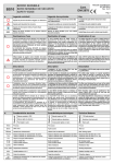
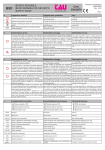
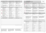
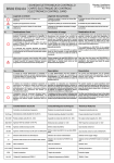
g.1.1
g.1.2
g.2
g.2.1
g.2.2
g.2.3
h.
Manutenzioni
Il bordo sensibile BS10 non necessita di
manutenzioni particolari, è consigliabile tuttavia
effettuare un controllo periodico (ogni 6 mesi).
Di ogni verifica deve essere mantenuta la
registrazione (vedi registro di manutenzione nel
manuale utente)
E' buona norma asportare eventuali sostanze
estranee effettuando una pulizia con aspiratori.
Apportare modifiche al sistema e/o alla sua
configurazione non concordate con il fabbricante
posso causare situazioni pericolose.
Qualsiasi intervento di manutenzione o taratura del
dispositivo dovrà essere effettuata da installatori
qualificati.
Verificare la presenza e la buona leggibilità della
marcatura d’identificazione del prodotto.
Information for the end user
BS10
Maintenance
Maintenance
Le bord sensible BS10 ne nécessite de aucune
maintenance particulière, mais un contrôle
périodique (tous les 6 mois)
e s t
recommandé.
Chaque contrôle doit être enregistré (voir le cahier de
maintenance dans le manuel de l'usager).
Il est bon d'emporter substances étrangères en
nettoyant avec aspirateurs.
Toutes modifications du dispositif peuvent provoquer
des situations dangereuses.
Les interventions de maintenance et tarage du
dispositif doivent être exécutées par des installateurs
qualifiés.
Vérifiez la présence et la lisibilité du marquage
d'identification du produit.
BS10 safety edge does not need special
maintenance, yet a periodic check (every 6 months)
is recommended.
Each check must be registered (see maintenance
register in the user manual).
It is recommended to remove any extraneous
substances cleaning with exhausters.
Any device modification can cause dangerous
situations.
Any intervention of maintenance and calibration of
the device must be realized by qualified fitters.
Check for presence and legibility of the marking of
product identification
Dépannage
Troubleshooting
Problema riscontrato:
Problème rencontré:
Problem found:
Bordo Sensibile non interviene
le bord sensible n'intervient pas
The safety edge does not intervene
Possibili cause:
Causes possibles:
Possible causes:
Guasto collegamenti
Liens défectueux
faulty links
Interventi da effettuare:
Opérations à réaliser:
Operation to be performed:
Porre l’automazione in «funzionamento manuale» e
rivolgersi all’assistenza
Placez l'automation en mode "manuel" et appelez
le support technique
Place the automation in "manual mode" and call for
service
Problema riscontrato:
Problème rencontré:
Problem found:
Bordo Sensibile interviene in ritardo
le bord sensible intervient en rétard
The safety edge intervenes late
Risoluzione dei problemi
Possibili cause:
Causes possibles:
Possible causes:
Tensionamento cavo acciaio insufficiente
Tension du câble en acier insuffisant
Low steel cable tension
Interventi da effettuare:
Opérations à réaliser:
Operation to be performed:
Rivolgersi all’assistenza
Appelez le support technique
Call for service
Problema riscontrato:
Problème rencontré:
Problem found:
Automatismo bloccato in posizione «aperta»
Automatisme bloqué en position “ouvert”
Automatic locked in “open” position
Possibili cause:
Causes possibles:
Bordo sensibile in allarme. Guasto sul
collegamento o perdita taratura
Bord de sécurité en état d'alarme. Problèmes de
connexions
Interventi da effettuare:
Opérations à réaliser:
Verificare che non vi siano oggetti che pongano il
bordo in «allarme» e rivolgersi all’assistenza
Vérifiez s'il y a des objets qui mettent le bord en
“alarm” et contactez le support technique
Registro delle manutenzioni
Cahier de maintenance
a.
MBS
b.
c.
Possible causes:
BORDO SENSIBILE
BORD SENSIBLE DE SECURITE
SAFETY EDGE
Cert.
EN12978
Manuale di Installazione
IST MDI BS10
Rev. 14-00
Pag.1
Legenda e simboli
Légende des symboles
Key
Segnala le parti del manuale da leggere con attenzione
Il signale les parties du manuel qui doivent être
lues soigneusement
It indicates the parts of the manual to be read
carefully;
Segnala parti riguardanti la sicurezza
Il signale les parties qui concernent la sécurité;
It indicates the parts related to safety;
Segnala le informazioni dirette all' utente finale
(utilizzatore)
Il signale les informations adressées à l'usager
final (utilisateur)
It indicates the information aimed to the final user
(consumer)
Misura del Bordo Sensibile che si desidera ottenere
(calotte comprese)
Mesure du Bord Sensible qu’on veut obtenir
(couvercle compris)
Safety Edge size you wish to obtain (cap included)
Destinazione d’uso
Destination d’usage
Destination of use
Il bordo sensibile BS10 viene utilizzato come dispositivo
di sicurezza su impianti di automazione per cancelli a
scorrimento orizzontale e ad anta, a protezione di rischi
di schiacciamento ed intrappolamento. La deformazione
della gomma provoca l'intervento del bordo sensibile
lungo tutta la sua altezza.
La conformità alla normativa EN12978 del sistema
formato dal bordo sensibile BS10 ed elettronica BS02E02/04 o similare, è subordinata al Test di Controllo da
parte della centrale di comando.
Le bord sensible BS10 est utilisé comme un
dispositif de sécurité dans des systèmes
d'automatisation pour portails coulissantes et à
battente, contre les risques de concassage et de
piégeage. La déformation du caoutchouc
provoque l'intervention du bord sensible sur toute
sa hauteur.
Conforme à la norme EN12978 dans un système
formé par le bord sensible BS10 et l’électronique
BS02-E02/04 ou similaire, est soumis à des tests
de contrôle de l'unité de commande.
The safety edge BS10 is used as a safety device for
automation sistems for sliding and swinging gates,
as protection against risks of crushing and trapping.
The deformation of the rubber causes the
intervention of the safety edge along its entire height.
Compliance to EN12978 rules of the system formed
by the edge sensitive BS10 and electronics BS02E02/04 or similar, it is subject to the Control Testing
by the control unit.
Utilizzi diversi da quanto sopra descritto del bordo
sensibile BS10 o installazione non eseguita in conformità
a quanto descritto nel seguente manuale possono
pregiudicare il corretto funzionamento del dispositivo.
Utilisations du bord sensible BS10 différentes de
ce qui a été ci-dessus décrit ou installations pas
exécutées en conformité avec ce qui est décrit
dans ce manuel peuvent compromettre le correct
fonctionnement du dispositif.
Uses of BS10 safety edge which are different from
what above mentioned or installations which are not
realized according to what described in this manual
can compromise the right working of the device.
Descrizione
Description
Description
L' installazione del bordo sensibile BS10 dovrà essere
eseguita da installatori qualificati.
L'installation du bord sensible BS10 doit être
exécutée par installateurs qualifiés.
The installation of BS10 safety edge must be realized
by qualified fitters.
Il bordo sensibile non necessita di particolari operazioni
di riarmo/riavvio da eseguire in seguito ad un'allarme del
dispositivo, in quanto il ripristino avviene
automaticamente. Per i guasti in cui permane l'allarme
del dispositivo, fare riferimento alla tabella g.2
"risoluzione dei problemi".
Le bord sensible ne nécessite pas d'opérations
spéciales de réinitialisation/remise à exécuter en
réponse à un alarme dans le dispositif, parce que
la récupération s'effectue automatiquement. Pour
les défauts qui maintient le dispositif en alarme,
reportez-vous au tableau g.2 «dépannage».
The safety edge requires no special operations
reset/ restart to execute in response to an alarm
device, as recovery takes place automatically. For
faults which keeps the device alarm, please refer to
the table g.2 "troubleshooting".
L'installatore deve far conoscere all'utente finale i
dispositivi di sicurezza e le loro caratteristiche ed istruirlo
in modo tale che le aree che danno accesso ai dispositivi
del sistema vengano mantenute libere da ostacoli.
L'installateur doit faire connaître à l’utilisateur final
les dispositifs de sécurité et leurs caractéristiques
et lui informer que les zones qui donnent accès au
système soyent maintenus libres de tout obstacle.
The fitter must introduce the end user to the safety
devices and their characteristics and inform him so
that the areas that give access to the system devices
must be kept free of obstacles.
ll bordo sensibile BS10 va posizionato in sede verticale
avendo cura di montare la scheda con i microswitches
nella parte superiore.
Le bord BS10 doit être placé à la verticale, en
prenant soin de monter la carte avec les micros
dans la partie supérieure.
BS10 Sensitive edge must be positioned in the
vertical, taking care to mount the card with the
microswitches in the upper part.
Il bordo sensibile BS10 è formato da un' estruso in
gomma con dopocorsa elastico di ammortamento urto e
da un profilo in alluminio che fissato alla colonna o al
cancello funge da supporto all' estruso.
Il funzionamento del dispositivo è garantito da 2
microswitches. Entrambi lavorano su deformazione della
costa comprensiva delle calotte morbide poste alle
estremità e come sicurezza nel caso in cui il cavo di
acciaio dovesse perdere tensione.
Le bord BS10 est formé par un caoutchouc
extrudé avec après-course d'amortissement de
choc élastique et par un profilé en aluminium qui
est fixé à la colonne ou à la grille et qui agit comme
un support. Le fonctionnement du dispositif est
garanti par 2 micro-interrupteurs. Les deux
travaillent sur la déformation de la barre y compris
les capuchons souples aux extrémités et comme
sécurité dans le cas où le câble d'acier perd sa
tension.
The safety edge BS10 is composed by an extruded
rubber with elastic after-run of amortization and an
aluminum profile that is fixed to the column or to the
gate and it acts as a support. The operation of the
device is guaranteed by 2 microswitches. Both work
on deformation of the edge including soft caps at the
ends if the steel cable lose tension.
Caratteristiche tecniche
Caractéristiques techniques
Technical features
Materials
g.1
Informations pour l’usager final
Matériels
Informazioni per l’utente finale
Safety edge in alarm. Failure connecting
Operation to be performed:
Verify if there are objects that place the edge in
"alarm" Call for service
Maintenance register
d.
Materiali
g.
TIMBRO DEL RIVENDITORE / TAMPON DU VENDEUR / DEALER STAMP
Estruso morbido in TPE
Estruso rigido in alluminio
Parti rigide in nylon
Pag.6
Extrudé rigide en aluminium
Composants rigides en nylon
TPE soft extruded
Aluminium hard extruded
Nylon parts
18mm
Precorsa
Pré-course
Pre-run
24mm
Oltre corsa
Aprés-course
After-run
12m/min
Velocità max di rilevamento
Vitesse max de relévement
Max. bearing speed
>0.15 s
>2 s
Tempo di risposta con avanzamento 12 m/min
Tempo di risposta con avanzamento a 0.6 m/min
Temps de réponse avec avancement à 12 m/min
Temps de réponse avec avancement à 0,6 m/min
Response time with feed 12 m / min
Response time with feed 0.6 m / min
<2s
Tempo di recupero deformazione
Temps de recouvrement
Distorsion recovery time
J1 NC
J1 R
Uscita contatto NC
Uscita contatto resistivo
Sortie contact NC
Sortie contact résistif
NC Contact output
Resistive Contact output
8,2 KΩ
Valore resistenza
Valeur résistance
Resistance value
Température d’exercise
Working temperature
-10°C / +60°C Temperatura d’esercizio
PiZero s.r.l. Via Luciano Cacace, 16 Martellago (VE) Italia - Tel. +39 041 5030772- Fax. +39 041 0997576 - www.pizero.it
Extrudé souple en TPE
93%
Umidità relativa a 40° C
Humidité relative à 40° C
Relative humidity at 40° C
IP54
Grado di protezione
Degré de protection
Protection degree
Categoria di appartenenza con elettronica di controllo
BS02-E02/04 o similari
Catégorie d'appartenance avec électronique de
contrôle BS02-E02/e04 ou similaires
Category of belonging with electronic control
BS02-E02/E04 or similar
2/3
EN954-1
Montaggio Bordo Sensibile
Montage du Bord Sensible
Safety Edge installation
L’installazione del Bordo Sensibile BS10 dovrà essere
eseguito da installatori qualificati
ATTENZIONE: Apportare modifiche al sistema e/o alla
sua configurazione non autorizzate dal fabbricante
possono causare situazioni pericolose.
L’installation du Bord Sensible BS10 doit être
exécutée par installateurs qualifiée
ATTENTION: Apporter des modifications au
système et/ou à sa configuration pas autorisés
par le fabricant peut causer des situations
dangereuses.
The installation of BS10 Dafety Edge must be
realized by qualified fitters
WARNING: Make changes to the system and/ or its
configuration not authorized by the manufacturer
may cause dangerous situations.
Fissaggio della costa
Fixage de la barre
Fixing of the safety edge
e.1.1
Per modificare l’altezza del bordo sensibile vedere le
istruzioni riportate al punto " f ".
Se non sono necessarie modifiche rimuovere la linguetta
passacavo trasparente (DIS.3 part.2)
Pour changer la hauteur du bord sensible suivre
les instructions données dans " f ".
Si aucune modification n'est necessaire,retirez
l'onglet transparent (DIS.3 part.2)
To change the height of the edge sensitive follow
the instructions given in " f ".
If no changes are necessary remove the
transparent tab (DIS.3 part.2)
e.1.2
Fissare le CLIP (DIS.1 part.1) alla colonna o al cancello Fixer le CLIP (DIS.1 part.1) à la colonne ou à la
facendo riferimento alle quote riportare nella TAB 1 (H1.1 grille en se référant à la TAB 1 (H1.1 / H 1,2 / H 1,3)
/ H 1.2 / H 1.3)
Fix the CLIP (DIS.1 part.1) to the column or to the
gate by reference to the shares back in TAB 1
(H1.1 / H 1.2 / H 1.3)
e.1.2
Inserire la costa nelle CLIP e fissarla alla colonna o al
cancello con i fori predisposti (DIS.1 part.2), vedi TAB 1
(H 2.1 / H 2.2)
Fit the edge to the CLIP in the column or in the gate
and secure with holes (DIS.1 part.2), see TAB 1 (H
2.1 / H 2.2)
e.1
e.2
e.3
e.4
MBS
Misura Bordo Sensibile
Dimension du Bord Sensible
Safety edge size
TAB. 1
Entrez la barre dans les CLIPS et fixez-la par les
trous à la colonne ou à la grille (DIS.1 part.2), voir
TAB 1 (H 2.1 / H 2.2)
f.3
Collegamento
Connexion
Connection
- Montato il Bordo Sensibile alla colonna o al cancello
eseguire i collegamenti della costa secondo lo schema
allegato (DIS.2 part.1)
- Il jumper J1 seleziona il tipo di contatto che si vuole
utilizzare sui morsetti di collegamento:
J1 NC = Contatto NC (DIS.2 part.2)
J1 R = Contatto resistivo 8,2 KΩ (DIS.2 part.3)
- Une fois assemblé le bord à la colonne ou à la
grille, effectuer les liens du bord selon le schéma
ci-joint (DIS.2 part.1).
- Le jumper J1 sélectionne le type de contact que
vous souhaitez utiliser avec les bornes de
raccordement:
J1 NC= Contact NC (DIS.2 part.2)
J1 R = Contact résistif 8.2KΩ (DIS.2 part.3)
- Once you have fix the safety edge to the coloumn or
to the gate, make connections to the edge, according
to the attached diagram (DIS.2 part.1)
- The jumper J1 selects the type of contact that you
want to use the connection terminals:
J1 NC= NC contact (DIS.2 part.2)
J1 R = Contact resistance 8,2KΩ (DIS.2 part.3)
Tensionatura cavo e taratura
Tension du câble et tarage
Cable tension and calibration
La costa viene già fornita con una pretensionatura del
cavo. E’ tuttavia possibile eseguire una ulteriore
regolazione della costa agendo sulla VITE (DIS.3 part.1)
posta sul braccio del supporto superiore della costa.
Ruotando in senso orario si aumenterà la sensibilità della
costa (+)
Ruotando in senso antiorario si diminuirà la sensibilità
della costa (-).
Il funzionamento ottimale del dispositivo si ottiene con
l'intervento elettrico dello stesso con una deformazione
al centro del bordo sensibile pari a circa 20 mm (DIS.4)
La barre est déjà fournie avec le câble
prétensioné. Cependant il est possible effectuer
un ajustement de la barre en tournant la VIS
(DIS.3 part.1) placée sur le bras de la partie
supérieure de la barre.
En tournant vers la droite la sensibilité de la barre
va augmenter (+)
Tournant vers la gauche la sensibilité de la barre
va diminuer (-)
Le fonctionnement optimal du dispositif est réalisé
à l'intervention électrique de la même avec une
déformation au centre de la barre égale à environ
20 mm (DIS.4)
The safety edge is already provided with the
pretensioned cable. However, you can make further
adjustment by turning the SCREW (DIS.3 part .1) on
the arm of the upper support of the edge.
Turning clockwise will increase the sensitivity the
coast (+)
Turning counterclockwise will decrease the
sensitivity the coast (-)
Optimum operation of the device is achieved with the
electrical intervention with a deformation at the
center of the safety edge equal to about 20 mm
(DIS.4)
Encastrement des capuchons
Positioning of the cap
- Pour encastrer le capuchon souple, le placer en
face de la plaque de support, en prenant soin de
faire glisser les extrémités libres dans leur sièges
(DIS.5 part.1) et les deux crochets latérals de
blocage à l'intérieur des fentes disposées (DIS.5
part.2). Appliquez une légère pression pour qu'il y
ait un déclic pour indiquer le positionnement
correct du capuchon.
Fixez le capuchon avec la vis fournie (DIS.5
part.3).
- Pour retirer le capuchon agir en sens inverse:
enlever la vis (DIS.5 part.3), relâchez le capuchon
en insérant un outil à l'intérieur des fentes en
poussant les crochets vers l'intérieur.
- To insert the soft cap, place it in front of the support
plate, taking care to slide the flaps in their seats
(DIS.5 part.1) and the two lateral locking hooks
inside of slits arranged (DIS.5 part.2). Apply light
pressure so that there is a click to indicate the correct
placement of the same. Secure the cover with the
screw provided (DIS.5 part.3).
- To remove the cover please act in reverse: remove
the screw (DIS.5 part.3), release the cap by inserting
a tool inside the slits pushing the hooks inward.
Nota
Note
Note
Allo scopo di migliorare lo scarico di eventuali sedimenti
che potrebbero formarsi all’interno della calotta inferiore
è consigliabile praticare un foro come indicato nel DIS.5
(part.4).
Afin d'améliorer l'évacuation de tout sédiment In order to improve the discharge of any sediment
pouvant se former à l'intérieur du capuchon that may find inside the bottom cap, it is advisable to
inférieur il est conseillé de percer un trou comme il drill a hole as shown in DIS.5 ( part.4).
est indiqué ci-après en DIS.5 (part.4).
Quote fissaggio Bordo Sensibile
Niveaux de fixation du Bord Sensible
H 1.1
H 1.2
Riassemblare il supporto superiore nel profilo in
alluminio ( DIS. 9 part .2)
Remonter le support supérieur sur le profilé
d'aluminium (DIS.9 part.2)
Reassemble the upper support in the aluminum
profile (DIS.9 part .2)
Riassemblare il cavetto di acciaio attraverso:
- Cavidotto ricavato nel bordo in gomma
( DIS. 10 part.1)
- Braccio mobile ( DIS. 10 part.2)
- Camma
( DIS. 10 part.3)
Solo una volta compiuta questa operazione si dovrà
sfilare la linguetta passacavo (DIS. 11 art.1)
Remonter le câble en acier à travers:
- Conduit logé dans le bord en caoutchouc
(DIS. 10 part.1)
- Bras réglable (DIS. 10 part.2)
- Came
(DIS. 10 part.3)
Ce n'est qu'une fois accomplie cette tâche, vous
devrez retirer l’onglett (DIS. 11 part.1)
Reassemble the steel cable through:
- Cable conduit housed in the rubber edge
(DIS.10 part.1)
- Adjustable jib (DIS. 10 part.2)
- Cam
(DIS. 10 part.3)
Only once accomplished this task you will have to
remove the transparent tab (DIS. 11 part.1)
- Precaricare la camma (DIS. 11 part.2) e bloccarla
con il fermo di rotazione dato in dotazione
( DIS. 11 part.3)
- Inserire il morsetto del cavo ( DIS. 11 part.4) e
bloccarlo
- Précharger la came (DIS. 11 part.2) et la bloquer
par l’arrêt de rotation fourni (DIS. 11 part.3)
- Insérez le serre-câble (DIS.11 part.4) et le
verrouiller
- Preload the cam (DIS. 11 part.2) and secure
with the supplied rotation latch (DIS.11 part. 3)
- Insert the cable clamp (DIS. 11 part.4) and lock
- Retirer l’arrêt de rotation (DIS. 11 part.3)
- Remove the rotation latch (DIS. 11 part.3)
- Procéder à la «Connexion» de la barre
selon "e.2" Pag.2
- Procéder à la «Tension du cable et tarage»
selon "e.3" Pag.2
- Procéder à l’ «Encastrement des capuchons»
selon "e.4» Pag.2
- Proceed to the "Connection" of the edget in
according to "e.2" Pag.2
- Proceed to «Cable tension and calibration» in
according to"e.3" Pag.2
- Proceed to "Positioning of the cap" in
according to "e.4" Pag.2
- Rimuovere il fermo di rotazione ( DIS. 11 part.3)
- Procedi al «Collegamento» della costa come
al p.to "e.2" Pag.2
- Procedi alla «Tensionatura cavo e taratura» come
al p.to "e.3" Pag.2
- Procedi alla "Inserimento delle calotte» come
al p.to "e.4" Pag.2
DIS. 9
DIS. 8
DIS. 10
PART.2
PART.1
PART.3
DIS. 11
Safety Edge fastening figures
PART.1
Altezza foro fiss. SUPPORTI (mm)
Hauteur trou fixation SUPPORTS (mm)
Height of the fixing hole for SUPPORTS (mm)
H 1.3
H 2.1
PART.4
H 2.2
PART.1
978
1.500 mm
1300
1.700 mm
1500
1478
1678
22
1000
1800
2.500 mm
1250
2300
2478
3.000 mm
1500
2800
2978
4.000 mm
2000
3800
3978
2.000 mm
Safety Edge installation
Slide the rubber in the aluminum profile
(DIS. 8 part.1).
When you have finished the rubber edge should
spill over 20mm compared to the aluminum profile
(DIS. 9 part.1)
PART.1
500
1.000 mm
Montage du Bord Sensible
Faites glisser le caoutchouc dans l’aluminium
(DIS. 8 part.1).
Lorsque vous avez terminé le bord en caoutchouc
devrait déborder sur 20mm par rapport au profil
d'aluminium (DIS.9 part.1)
PART.2
Inserimento delle calotte
- Per inserire la calotta morbida, posizionarla
frontalmente alla piastra di supporto, avendo cura di fare
scorrere le alette terminali nelle proprie sedi di
contenimento (DIS.5 part.1) e i due ganci laterali di
bloccaggio all’interno delle feritoie predisposte (DIS.5
part.2). Applicare una leggera pressione affinchè vi sia
uno scatto ad indicare il corretto collocamento della
stessa.
Fissare la calotta con la vite in dotazione (DIS.5 part.3).
- Per rimuovere la calotta agire in maniera inversa:
togliere la vite di testa (DIS.5 part.3), sganciare la calotta
inserendo un utensile all’interno delle feritorie spingendo
i ganci verso l’interno.
Altezza foro fiss. CLIP (mm)
Hauteur trou fixation CLIP(mm)
Height of the fixing hole for CLIP (mm)
Montaggio del bordo sensibile
Improfilare l'estruso in gomma nel profilo di alluminio
( DIS. 8 part.1).
Ad operazione conclusa il bordo in gomma dovrebbe
debordare di 20mm rispetto al profilo in alluminio
(
DIS. 9 part.1)
20mm
e.
1978
200
PART.2
Pag.2
PRECARICA
PRECHARGE
PART.3
Pag.5
DIS. 1
f.
DIS. 3
f.1
+
PART.2
PART.2
PART.1
PART.1
f.2
Modificare altezza bordo sensibile Changer la hauteur du bord sensible Change the safety edge size
Démontage du Bord Sensible
Retirez le serre-câble (DIS. 6 part.1)
Remove the cable clamp (DIS.6 part.1)
Non rimuovere la linguetta passacavo trasparente.
Ne pas retirer l'onglet transparent.
Do not remove the transparent tab .
Sfilare il cavetto di acciaio dal supporto superiore e
dalla gomma , fino al supporto inferiore della costa
( DIS. 7 part.1)
Débranchez le câble d'acier à partir du support
supérieur, longt le caoutchouc jusqu'au support
inférieur (DIS. 7 part.1)
Remove the steel cable from the top bracket and the
rubber until the lower support
(DIS. 7 part.1)
Togliere il supporto superiore dal profilo in alluminio
( DIS. 7 part.2)
Enlever le support supérieur du profil d'aluminium
(DIS. 7 part.2)
Remove the upper support from the aluminum profile
( DIS. 7 part.2)
Sfilare completamente l'estruso in gomma dal profilo
di alluminio ( DIS. 7 part.3)
Retirer completement le caoutchouc de l'aluminium
(DIS. 7 part.3)
Withdraw the rubber from aluminum bar
(DIS. 7 part.3)
Modifica altezza
Modification de la longueur
Size changing
Tagliare l’estruso in alluminio ed il profilo in gomma
della stessa misura per ottenere l’altezza desiderata.
Il bordo in gomma deve risultare 40mm più lungo del
profilo in alluminio.
Couper l'aluminium et le caoutchouc de la même
taille pour obtenir la hauteur souhaitée.
Le bord en caoutchouc doit être de 40 mm plus long
que le profilé en aluminium.
Cut the extruded aluminum and the rubber in the
same size to get the desired height.
The rubber edge should be 40mm longer than the
aluminum profile.
ES. - Pour obtenir un bord à
ES. - To get a edge of
ES. - Per ottenere una costa da
MBS = 1800 mm
Estruso in gomma = MBS mm - 245 mm = 1555 mm
Profilo in alluminio = MBS mm - 285 mm = 1515 mm
PART.1
Safety Edge disassembly
Smontaggio del bordo sensibile
Rimuovere il morsetto del cavo ( DIS. 6 part.1)
MBS = 1800 mm
MBS = 1800 mm
Extrudés caoutchouc = MBS mm - 245 mm = 1555mm Extruded Rubber = MBS mm - 245 mm = 1555 mm
Profilé aluminium
= MBS mm - 285 mm = 1515 mm Aluminum profile = MBS mm - 285 mm = 1515 mm
DIS. 4
DIS. 6
DIS. 7
PART.2
PART.1
<
20 mm
DIS. 5
PART.2
PART.1
PART.3
PART.1
DIS. 2
PART.1
PART.2
PART.2
J1=NC
PART.1
PART.3
J1=8.2KΩ
INGRESSO CAVI
ENTREE CABLES
CABLE ENTRY
PART.3
PART.4 Ø5mm
Pag.3
Pag.4