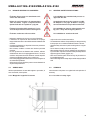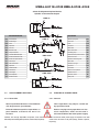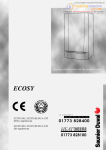
1
C O N D I T I O N I N G
11.09
MUI01110E2001-01
06.14
Sostituisce/Remplace
Catalogo/Bruchure
HWAL-A 0118÷0120
HWA-A 0125÷0142
AIRCOOLED LIQUID CHILLERS AND HEAT
PUMPS WITH AXIAL FANS, ROTARY/
SCROLL COMPRESSORS AND PUMP
SECTION FROM 25 kW TO 42 kW
Serie/Series
REFRIGERATORI D'ACQUA E POMPE
DI CALORE ARIA/ACQUA CON
VENTILATORI ASSIALI, COMPRESSORI
ROTATIVI/SCROLL E GRUPPO DI
POMPAGGIO DA 25 kW A 42 kW
Emissione/Edition
MANUALE UTENTE-INSTALLATORE
INSTALLATION AND OPERATION MANUAL
A I R
A45
HWAL-A 0118÷0120 HWA-A 0125÷0142
0.
ELENCO DOCUMENTI ALLEGATI
Elenco documentazione fornita a corredo della macchina facente
parte integrante del presente manuale.
2
0.
LIST OF ATTACHMENTS
List of documents supplied with the unit and forming an integral part
of this manual.
- Quaderno tecnico
- Technical book
- Manuale microprocessore
- Microprocessor manual
- Certificato di garanzia
- Certificate of guarantee
HWAL-A 01185÷0120 HWA-A 0125÷0142
INDICE
CONTENTS
Argomento
Subject
0
ELENCO DOCUMENTI ALLEGATI
0
LIST OF ATTACHMENTS
1
PREMESSA
1
INTRODUCTION
1.1
1.2
1.3
Informazioni generali
Allegati
Avvertenze
1.1
1.2
1.3
General information
Attachments
Warnings
2
DESCRIZIONE DELLA MACCHINA
2
UNIT DESCRIPTION
2.1
2.1.1
2.2
2.3
2.4
Identificazione
Identificazione della macchina
Destinazione d'uso
Controindicazioni
Descrizione generale
2.1
2.1.1
2.2
2.3
2.4
Identification
Identification
Intended use
Contraindications
General description
3
SICUREZZA
3
SAFETY
3.1
3.2
3.3
3.3.1
3.3.2
3.4
3.5
3.5.1
3.5.2
Definizioni
Regole generali di sicurezza
Simbologia
Mappa dei segnali di sicurezza
Segnali di sicurezza
Dispositivi di emergenza e di sicurezza
Descrizione del rischio residuo
Rischio residuo in prossimità della macchina
Misure da adottare in caso di fuoriuscita di gas frigorigeno
Operazioni con rimozione dei pannelli
3.1
3.2
3.3
3.3.1
3.3.2
3.4
3.5
3.5.1
3.5.2
3.5.3
Definition
General safety regulations
Symbols
Location of safety signs
Safety signs
Emergency and safety devices
Description of residue risks
Residue risks near the unit
Measures to take in case of leaking refrigerant gas
Operations with the panels removed
ISPEZIONE, TRASPORTO
4
INSPECTION AND TRANSPORT
Ispezione
Stoccaggio
Sollevamento e trasporto
Disimballo
4.1
4.2
4.3
4.4
Inspection
Storage
Lifting and transport
Unpacking
5
INSTALLAZIONE
5
INSTALLATION
5.1
5.2
5.2.1
Scelta del luogo di installazione
Collegamento idraulico
Generalità
5.1
5.2
5.2.1
Choosing the installation site
Water connections
General
3.5.3
4
4.1
4.2
4.3
4.4
3
HWAL-A 0118÷0120 HWA-A 0125÷0142
5.2.2
5.3
5.3.1
5.3.2
Evaporatore
Collegamenti elettrici
Generalità
Consensi esterni
5.2.2
5.3
5.3.1
5.3.2
Evaporator
Electrical connections
General
External signals
6
AVVIAMENTO
6
START UP
6.1
6.2
6.3
6.3.1
6.3.2
6.1
6.2
6.3
6.3.1
6.3.2
6.4
Controlli preliminari all'avviamento
Messa in funzione
Verifiche durante il funzionamento
Generalità
Sbrinamento
(Solo unità pompa di calore)
Arresto del gruppo
6.4
Preliminary controls
Start up
Checks during unit operation
General
Defrosting
(Only heat pump units)
Stopping the unit
7
FUNZIONAMENTO
7
OPERATION
7.1
7.2
Generalità
Fermata stagionale
7.1
7.2
General
Seasonal shut down
8
RICERCA GUASTI
8
TROUBLE SHOOTING
9
MANUTENZIONE E CONTROLLI PERIODICI
9
ROUTINE MAINTENANCE AND CONTROLS
9.1
9.1.1
9.1.2
9.2
9.3
Avvertenze
Generalità
Controlli mensili
Controlli quadrimestrali
Riparazioni del circuito frigo
Rabbocchi di refrigerante
9.1
9.1.1
9.1.2
9.2
9.3
Warnings
General
Monthly controls
Four-monthly controls
Repairing the refrigerant circuit
Topping up the refrigerant liquid
10
DISMISSIONE E SMALTIMENTO
10
SHUT DOWN AND DISPOSAL
4
HWAL-A 01185÷0120 HWA-A 0125÷0142
1.
PREMESSA
1.
INTRODUCTION
1.1
INFORMAZIONI GENERALI
1.1
GENERAL INFORMATION
Questo manuale contiene le norme di installazione, uso e manutenzione dei refrigeratori HWAL-A - HWA-A, evidenziandone rischi e
pericoli connessi. Esso è stato espressamente studiato e sviluppato
per permettere al personale preposto un utilizzo facile e in sicurezza
dei refrigeratori d'acqua HWAL-A - HWA-A. Leggere attentamente
e completamente tutte le informazioni in esso riportate. Prestare
particolare attenzione alle norme evidenziate con
This manual contains the installation, use and maintenance instructions for the HWAL-A - HWA-A chillers, and highlights all connected
risks and perils. It has been expressly prepared and written to allow
authorised users to use the HWAL-A - HWA-A water chillers in complete safety and with the greatest of ease. Please read the whole
of this manual with care, paying special attention to the sections
marked with
in quanto se non osservate possono causare danno alle persone,
all'ambiente e/o alla macchina stessa.
La società declina ogni responsabilità per qualsiasi uso improprio
della macchina, per modifiche alla stessa non autorizzate o per la
non osservanza delle norme riportate sul manuale. Il manuale deve
essere conservato in luogo sicuro e messo a disposizione del personale addetto alla conduzione ed alla manutenzione del refrigeratore.
as non-compliance may cause harm to people, deteriorate the
environment and/or damage the unit.
The company declines all responsibility for any improper use of
the unit, unauthorised modifications or non-compliance with the
instructions contained in this manual.
Please keep this manual in a safe place and make it available to
chiller operators and maintenance men.
1.2
1.2
ALLEGATI
Fanno parte integrale del presente manuale i documenti evidenziati
a pag. 2.
The documents shown on page 2 form an integral part of this manual.
1.3
1.3
ATTACHMENTS
WARNINGS
AVVERTENZE
Le unità HWAL-A - HWA-A sono state progettate e costruite per garantire nel tempo grande affidabilità di esercizio e massima sicurezza;
per questo e grazie alle scelte progettuali e realizzative, la società
può garantire la totale conformità agli standard di sicurezza CE.
Ulteriore garanzia è assicurata dai collaudi cui la macchina è stata
sottoposta in fabbrica.
All'utente resta quindi soltanto l'impegno di un uso proprio e di una
manutenzione preventiva conforme alle indicazioni contenute in
questo manuale.
Ogni intervento, di qualsiasi natura, sulla
macchina deve essere preceduto da una
attenta lettura del presente manuale in tutte
le sue parti.
The HWAL-A - HWA-A units have been designed and built to ensure
long-term operating reliability and maximum safety; for this reason
and thanks to the company's design and construction policy, the
company is able to guarantee that this product totally complies with
EC safety standards.
A further guarantee of this is provided by the factory tests carried
out on the unit.
The user, therefore, must only ensure the unit is properly used and that
maintenance operations are carried out according to the indications
contained in this manual.
The unit should not be touched until the
whole of this manual has been carefully read.
5
HWAL-A 0118÷0120 HWA-A 0125÷0142
Il manuale di installazione, uso e manutenzione deve essere sempre a disposizione
degli addetti, i quali, prima di ogni operazione
sulla macchina, devono obbligatoriamente
leggerlo.
Per ogni ulteriore informazione e chiarimento
MAXA. si rende disponibile al seguente indirizzo:
Via Gettuglio Mansoldo (Loc. La Macia)
37040 Arcole - Verona - Italy
Tel. +39 - 045.76.36.585
Fax +39 - 045.76.36.551
6
This installation, use and maintenance manual must always be kept within easy reach
of authorised staff who are obliged to read
it before carrying out any operations on the
unit.
For any further information or explanations please contact MAXA.
at the following address:
Via Gettuglio Mansoldo (Loc. La Macia)
37040 Arcole - Verona - Italy
Tel. +39 - 045.76.36.585
Fax +39 - 045.76.36.551
HWAL-A 01185÷0120 HWA-A 0125÷0142
2
DESCRIZIONE DELLA MACCHINA
2
UNIT DESCRIPTION
Questo capitolo ha lo scopo di fornire una descrizione generale delle
caratteristiche principali della macchina nel suo insieme, unitamente
a quella dei principali componenti, standard e opzionali.
This chapter contains a general description of the main unit HWAL-Characteristics, together with those of its principal standard and
optional components.
2.1
2.1
IDENTIFICAZIONE
IDENTIFICATION
2.1.1 Identificazione della macchina
2.1.1 Unit identification
La macchina si identifica tramite le targhette poste sul telaio e sul
quadro elettrico. Le targhette riportano i seguenti dati:
The unit can be identified throug the plats attached on the frame and
in the electrical box. This label contains the following information:
-
-
Ragione sociale del costruttore
Indirizzo del costruttore
Designazione della serie e del tipo di unità
Numero di matricola
Anno di costruzione
Tipo e quantità di refrigerante
Massima pressione ammissibile
Taratura dei pressostati
Simbolo della certificazione CE
Caratteristiche elettriche
Identificazione schema elettrico
Manufacturer's name
Manufacturer's address
Description of the series and type of unit
Series number
Year of construction
Type and quantity of refrigerant liquid
Max. Allowable pressure
Pressure switch set point
EC certification symbol
Electrical characteristics
Wiring diagram identification
7
HWAL-A 0118÷0120 HWA-A 0125÷0142
2.2
DESTINAZIONE D'USO
I HWAL-A - HWA-A sono refrigeratori con condensazione ad aria
destinati a raffreddare acqua (eventualmente addizionata con glicole
etilenico inibito) che circola in un anello chiuso. Le unità a pompa
di calore possono, a seconda del ciclo di funzionamento scelto,
raffreddare o riscaldare l'acqua dell'anello.
Il caldo, o il freddo, così prodotto può essere utilizzato per impianti
di climatizzazione o per processi industriali.
2.2
The HWAL-A - HWA-A series of air condensation chillers have been
designed to cool water (possibly containing inhibited ethylene glycol)
circulating in a closed circuit. The heat pump units can cool or heat the
water in the closed circuit depending on which operating cycle is chosen.
The heat or cold produced can be used for air-conditioning systems
or industrial processes.
2.3
2.3
Do not use inflammable products near the
unit.
Do not use substances that can form explosive mixtures near the unit.
Non impiegare in prossimità della macchina sostanze in grado di formare miscele
esplosive.
Do not use the unit in conditions that could
be harmful for the environment (see point
3.5 on page 13).
Non impiegare la macchina dove sussistono
problemi di impatto ambientale (vedi punto
3.5 pag. 13).
2.4
GENERAL DESCRIPTION
DESCRIZIONE GENERALE
Tutte le strutture sono realizzate in peraluman. La struttura è autoportante ed i pannelli sono facilmente rimovibili in modo da permettere
l'accesso all'interno della unità per le operazioni di manutenzione
e riparazione.
3
SICUREZZA
3.1
DEFINIZIONI
In questo documento verranno utilizzate le seguenti definizioni:
- Zone pericolose: qualsiasi zona all'interno e/o in prossimità della
macchina in cui la presenza di una persona esposta costituisca
un rischio per la sicurezza e la salute di detta persona.
- Persona esposta: qualsiasi persona che si trovi internamente
o in parte in una zona pericolosa.
- Operatore/Manutentore: la o le persone incaricate di far funzionare, regolare, eseguire la manutenzione, riparare, movimentare
la macchina.
8
CONTRAINDICATIONS
CONTROINDICAZIONI
Non impiegare in prossimità della macchina
prodotti infiammabili.
2.4
INTENDED USE
All the unit structures are made from peraluman. The structure is
free standing and the panels are easy to remove in order to allow
access to the inside of the unit for maintenance and repair operations.
3
SAFETY
3.1
DEFINITION
This document uses the following definitions:
- Dangerous areas: any area inside and/or near to the unit in
which the presence of a person would give rise to a risk for that
person's health.
- Exposed person: anyone who is wholly or partly inside a
dangerous area.
- Operator/Maintenance man: person or persons authorised
to operate, adjust, service, repair or move the unit.
HWAL-A 01185÷0120 HWA-A 0125÷0142
3.2
REGOLE GENERALI DI SICUREZZA
3.2
GENERAL SAFETY REGULATIONS
È vietato alle persone non autorizzate avvicinarsi alla macchina.
It is forbidden for unauthorised persons to
approach the unit.
Prima di ogni intervento di manutenzione
sulla macchina, seguire scrupolosamente
quanto indicato nel capitolo 9 a pag. 30.
Scrupulously observe the contents of HWAL-Chapter 9 on page 30 before carrying
out each maintenance operation on the unit.
È vietata la rimozione delle protezioni e l'esclusione dei dispositivi di sicurezza e di emergenza.
It is forbidden to remove safety guards and
by-pass safety and emergency devices.
È vietato stazionare sulla macchina.
It is forbidden to stand on the unit.
- Impiegare la macchina solo per l'uso a cui essa è destinata.
- Il costruttore non risponde dei danni derivanti da un impiego
improprio della macchina o da modifiche tecniche effettuate sulla
macchina.
- Controllare regolarmente se i dispositivi di sicurezza presentano
un funzionamento corretto.
- Non smontare, modificare o mettere fuori funzione parti della
macchina.
- Per tutti gli interventi da effettuare sulla macchina, utilizzare
esclusivamente attrezzi ed equipaggiamenti idonei e in buone
condizioni. Gli operatori dovranno indossare i normali dispositivi
di protezione individuali (guanti, casco, occhiali, ecc.).
- I lavori sull'equipaggiamento elettrico devono essere eseguiti solo
da un elettricista qualificato.
- Gli interventi sul circuito frigorifero possono essere effettuati solo
da personale specializzato.
3.3
SIMBOLOGIA
- Only use the unit to do what it was built for.
- The manufacturer declines all responsibility for damage deriving
from improper use or technical modifications made to the unit.
- Check the safety devices are in perfect working order on a regular
basis.
- Do not dismount, modify or disconnect unit parts.
- When working on the unit, only use suitable tools and equipment
in good condition. Operators must wear normal personal protection
equipment (gloves, helmet, goggles, etc.).
- Work on the electrical system of the unit may only be carried out
by a qualified electrician.
- Work on the refrigerant circuit may only be carried out by specialised
staff.
3.3
SYMBOLS
Verificare periodicamente lo stato delle targhette e provvedere, in
caso di necessità, al loro ripristino.
Check the state of the plates on a regular basis and repair them if
necessary.
3.3.1 Mappa dei segnali di sicurezza
3.3.1 Location of safety signs
9
HWAL-A 0118÷0120 HWA-A 0125÷0142
3.3.2 Segnali di sicurezza
3.3.2 Safety signs
1
INGRESSO ACQUA REFRIGERATA
CHILLED WATER INLET
KALTWASSEREINTRITT
ENTRÉE EAU GLACÉE
2
USCITA ACQUA REFRIGERATA
CHILLED WATER OUTLET
KALTWASSERAUSTRITT
SORTIE EAU GLACÉE
3
SFIATO ARIA
AIR PURGE
ENTLÜFTUNGSVENTIL
PURGE AIR
4
5
RUBINETTO DI CARICO
PLANT JWARGE SHUT OFF VALVE
ANLAGE DRUCK MIT ABSPERRVENTIL
ROBINET DE JWARGE INSTALLATION
6
8
- PRESENZA DI ORGANI IN MOVIMENTO
- PRESENCE OF MOVING OBJECTS
- ANWESENHEIT VON GEGENSTÄNDEN
IN BEWEGUNG
- PRESENCE DES ORGANS EN MOUVEMENT
RUBINETTO DI SCARICO
PLANT DISJWARGE SHUT OFF VALVE
ANLAGE ABFLUSS MIT ABSPERRVENTIL
ROBINET DE DÉJWARGE INSTALLATION
10
7
HWAL-A 01185÷0120 HWA-A 0125÷0142
3.4
DISPOSITIVI DI EMERGENZA
E DI SICUREZZA
3.4
Un dispositivo di emergenza che tolga tensione dalla macchina deve essere previsto
all'esterno della stessa a cura di chi installa
la macchina.
3.5
DESCRIZIONE DEL RISCHIO RESIDUO
La descrizione del rischio residuo prende in considerazione i seguenti elementi:
- a quale tipologia di pericoli è soggetto chi opera nell'ambito della
macchina;
- la descrizione dei principali pericoli;
- chi può essere esposto a tali pericoli;
- quali sono le principali misure di sicurezza adottate per ridurre il
rischio di infortuni.
Le indicazioni per la prevenzione degli infortuni di seguito riportate,
con riferimento alle relative aree a rischio residuo, devono essere
integrate con tutte le indicazioni generali del presente capitolo e con
le norme di prevenzione infortuni vigenti nel paese di destinazione
dell'impianto.
EMERGENCY AND SAFETY DEVICES
An emergency external circuit breaker must
be fitted by the unit installer to disconnect
the unit from the power supply.
3.5
DESCRIPTION OF RESIDUE RISKS
The description of residue risks includes the following elements:
- the kind of danger the people working on the unit are subjected
to;
- description of the main dangers;
- who is exposed to such dangers;
- the main safety methods used to reduce the risk of injury.
The following accident prevention instructions, with reference to the
relative areas concerned by residue risks, must be integrated with all
the general indications contained in the present chapter and with the
accident prevention regulations in force in the country of installation.
3.5.1 Residue risks near the unit
3.5.1 Rischio residuo in prossimità della macchina
- Folgorazione, se non vengono effettuati correttamente l'allacciamento elettrico e la messa a terra della macchina.
- Tagli o escoriazioni per la presenza di superfici taglienti.
- Aspirazione e successiva dispersione in ambiente delle sostanze
presenti sul luogo dell'installazione.
- Proiezione di eventuali oggetti che possano cadere sulle pale dei
ventilatori.
- Fuoriuscita di acqua (in caso di anomalia).
- Formazione di acqua di condensa e di ghiaccio nella zona antistante la macchina durante il funzionamento in riscaldamento
delle macchine a pompa di calore.
- Alterazione del microclima (durante il funzionamento).
- Emissione di rumore (durante il funzionamento).
- Fuoriuscita di olii (per anomalia).
- Fuoriuscita del frigorigeno (per anomalia).
N.B. Il frigorigeno è una sostanza ad effetto serra. Si tratta di vapori
più pesanti dell'aria e che possono provocare soffocamento
riducendo l'ossigeno disponibile per la respirazione. Una
rapida evaporazione del liquido può causare congelamento.
- Electrocution if the unit is not properly corrected to the mains
power supply and earth circuit.
- Cuts or abrasions caused by sharp surfaces.
- Extraction and subsequent dispersion in the environment of
substances present in the installation site.
- Ejection of objects falling on the fan blades.
- Leaking water (in case of malfunction).
- Formation of condensation and ice in front of the unit while the
unit heat pumps are working.
- Alteration of the micro climate (during operation).
- Noise (during operation).
- Leaking oil (in case of malfunction).
- Leaking refrigerant liquid (in case of malfunction).
N.B. Refrigerant liquid is a substance which causes a greenhouse
effect. Its vapours are heavier than air and can cause
suffocation by reducing the amount of oxygen available for
breathing. Rapid evaporation of the liquid can cause freezing
to occur.
11
HWAL-A 0118÷0120 HWA-A 0125÷0142
3.5.2 Misure da adottare in caso di fuoriuscita
di gas frigorigeno
3.5.2 Measures to take in case of leaking
refrigerant gas
- Tipo di prodotto:
R410A
- Product type:
R410A
- Misure di pronto soccorso:
Informazione generale:
non somministrare alcunchè a persone svenute.
Inalazione:
portare all'aria aperta. Ricorrere all'ossigeno o alla respirazione artificiale se necessario. Non somministrare adrenalina o
sostanze similari.
Contatto con gli occhi:
sciacquare accuratamente ed abbondantemente con acqua per
almeno 15 minuti e rivolgersi ad un medico.
Contatto con la pelle:
Lavare subito abbondantemente con acqua. Togliersi immediatamente tutti gli indumenti contaminati.
- First aid measures:
General information:
Do not give anything to people who have fainted.
Inhalation:
take the person out into the open air. Use oxygen or artificial
respiration if necessary. Do not give adrenaline or similar substances.
Contact with eyes:
carefully rinse with abundant water for at least 15 minutes and
see a doctor.
Contact with the skin:
Wash with abundant water and remove all contaminated clothing
immediately.
- Misure in caso di fuoriuscita accidentale:
Precauzioni individuali:
evacuare il personale in aree di sicurezza. Prevedere una
ventilazione adeguata. Usare mezzi di protezione personali.
Precauzioni ambientali:
intercettare l'emissione.
Metodi di pulizia:
impiegare prodotti assorbenti.
- Measures to take in case of accidental leaking:
Personal precautions:
evacuate all staff to safety areas. Make sure the area is suitably
ventilated. Use personal protection equipment.
Environmental precautions:
to intercept the emission.
Cleaning methods:
to employ absorbent products.
3.5.3 Operazioni con rimozione dei pannelli
3.5.3 Operations with the panels removed
Alcune delle operazioni e/o verifiche di seguito descritte richiedono
la rimozione dei pannelli del refrigeratore per accedere all'interno
dello stesso.
Some of the following operations and/or controls require the panels
of the unit to be removed in order to access the inside of the unit.
Prima di rimuovere qualsiasi pannello perimetrale, eccezion fatta per quello che
protegge il quadro elettrico, è obbligatorio
togliere tensione.
Si fa presente che all'interno dell'unità, anche a macchina ferma
possono esserci superfici calde (tubazioni, compressore, ecc.), o
fredde (compressore, separatore d'aspirazione, ecc.), taglienti (alette
batterie) o corpi in movimento (ventilatori).
Pertanto tali operazioni devono essere effettuate solo da personale qualificato che
indossi indumenti di sicurezza.
12
Before removing an outer panel, except for
the one protecting the electrical panel, the
unit must be disconnected from the mains
power supply.
Please note that some surfaces inside the unit may be hot (piping,
compressor, etc.), cold (compressor, suction separator, etc.), sharp
(coil fins) or moving (fans) even when the unit is not working.
These operations may only be carried out
by qualified staff wearing safety clothing.
HWAL-A 01185÷0120 HWA-A 0125÷0142
Verifiche di funzionamento possono richiedere il funzionamento (totale
o parziale dell'unità) con un pannello aperto. In tal caso il pannello
va rimosso a macchina ferma.
Queste verifiche sono particolarmente pericolose e sono pertanto riservate a personale
altamente qualificato.
Operating checks may require the unit to work (totally or partially)
while a panel is open. In this case the panel should be removed
when the unit is not working.
These checks are particularly dangerous and
may only be carried out by highly qualified
staff.
Operare come segue:
Proceed as follows:
- Togliere tensione tramite il sezionatore generale.
- Aprire il quadro elettrico e disattivare, togliendo i relativi fusibili,
gli organi di cui non è necessario il funzionamento per la verifica
che si deve effettuare.
- Richiudere il quadro elettrico.
- Rimuovere il pannello interessato.
- Avviare l'unità.
- Effettuare le verifiche richieste con la massima cautela e con
l'utilizzo di protezioni individuali.
- Completate le verifiche, arrestare l'unità e rimettere al suo posto
il pannello precedentemente tolto.
- Togliere tensione e rimettere al loro posto gli eventuali fusibili
precedentemente tolti.
- Richiudere il quadro elettrico.
- Turn off mains power with the main power switch.
- Open the electrical panel and remove the relative fuses to disconnect the components that do not need to be working in order
to carry out the relative check.
- Close the electrical panel.
- Remove the panel in question.
- Start the unit.
- Carry out the relative check with the greatest of care and using
personal protection equipment.
- After completing the check, stop the unit and put the panel back
in place.
- Turn off mains power and put back any fuses that were previously
removed.
- Close the electrical panel.
13
HWAL-A 0118÷0120 HWA-A 0125÷0142
4.
ISPEZIONE, TRASPORTO
4.
INSPECTION AND TRANSPORT
4.1
ISPEZIONE
4.1
INSPECTION
All'atto del ricevimento dell'unità, verificarne l'integrità. Poiché la macchina è stata accuratamente controllata prima di lasciare la fabbrica,
eventuali danni sono da imputare al trasportatore. Si raccomanda
perciò di annotarli sul Foglio di Consegna prima di controfirmarlo.
Avvisare tempestivamente la società o l'Agente sull'entità del danno
riportato dall'unità.
Il Cliente deve sempre compilare un rapporto scritto che riguarda
ogni eventuale danno subito dalla macchina.
Check the condition of the unit on receipt. As the unit was carefully
checked before leaving the factory, any claims for damages should
be addressed to the forwarder. Any damage should therefore be
indicated on the Delivery Note before signing it.
Please inform the company or the Agent of the nature of the damage
to the unit immediately.
The Customer must always write a report describing any damage
caused to the unit.
4.2
4.2
STOCCAGGIO
STORAGE
La temperatura dell'ambiente in cui vengono immagazzinate le unità
deve essere compresa tra -20 e +50°C.
The temperature in the area where the units are stored must range
between -20 and +50°C.
4.3
4.3
SOLLEVAMENTO E TRASPORTO
Durante lo scarico ed il posizionamento dell'unità, prestare molta
attenzione alle manovre che non devono in alcun modo essere
brusche e/o violente. Non utilizzare come punti di sollevamento le
tubature o altri componenti della macchina.
When unloading and positioning the unit, take great care not to make
sudden and/or violent manoeuvres. Do not lift the unit by its piping
or any other components.
The unit should only be moved as shown in the plate attached to it.
Attenzione!
In tutte le operazioni di sollevamento assicurarsi di aver ancorato saldamente l'unità
per evitare ribaltamenti o cadute accidentali.
4.4
DISIMBALLO
L'imballo va tolto solo quando l'unità è giunta sul posto di installazione
e non dovrà più essere movimentata.
Rimuovere con cura l'imballo della macchina, evitando di danneggiare la stessa.
Poiché i materiali che costituiscono l'imballo sono di natura diversa
(legno, nylon, polistirolo, cartone, ecc.), si consiglia di conservarli separatamente e di consegnarli alle ditte specializzate nello smaltimento
e nel riciclaggio degli stessi allo scopo di salvaguardare l'ambiente.
14
LIFTING AND TRANSPORT
Attention!
Make sure the unit is securely anchored
before lifting it in order to prevent it from
accidentally overturning or falling.
4.4
UNPACKING
Only unpack the unit when it has reached the installation site and
no longer needs to be moved.
Remove the packing material with care, making sure not to damage
the unit.
Given that various kinds of packing materials are used (wood, nylon,
polystyrene, cardboard, etc.), they should be separated and delivered
to specialised disposal and recycling companies for environmental
reasons.
HWAL-A 01185÷0120 HWA-A 0125÷0142
5
INSTALLAZIONE
5
INSTALLATION
5.1
SCELTA DEL LUOGO DI INSTALLAZIONE
5.1
CHOOSING THE INSTALLATION SITE
Nella scelta del luogo di installazione si dovrà tenere conto di:
- Peso dell'unità:
La soletta di appoggio dell'unità deve essere
perfettamente orizzontale ed in grado di sopportare il peso in funzionamento dell'unità.
È opportuno costruire una soletta di supporto di dimensioni proporzionate all'unità. Ciò si rende in particolar modo necessario
quando l'unità deve essere posta su terreno instabile (giardini,
terreni di riporto, ecc.).
La soletta deve:
- appoggiare su opportune fondamenta, avere un'altezza, rispetto
al terreno circostante, di circa 10-15 cm;
- essere orizzontale ed in grado di sopportare circa il 200% del
peso di esercizio della macchina.
- Spazi:
È necessario verificare che gli spazi di rispetto riportati sul foglio dimensionale dell'unità
siano lasciati liberi.
Ridurre lo spazio richiesto può significare difficoltà o impossibilità
di effettuare le operazioni di manutenzione e/o malfunzionamento
dell'unità a causa di riduzione della portata d'aria che investe la
batteria condensante o di ricircolo della stessa.
Si fa presente che non sono ammessi ostacoli quali tettucci, pensiline o coperture in
genere al di sopra della macchina.
When choosing the installation site the following points should be
considered:
- The weight of the unit:
The supporting surface under the unit must
be perfectly horizontal and able to withstand
its operating weight.
A supporting surface with an appropriate area should be built. This
is particularly important if the unit is installed on unstable ground
(gardens, embankments, etc.).
The supporting surface must:
- lie on suitable foundations and be about 10-15 cm higher than
the surrounding ground;
- be horizontal and able to withstand about 200% of the weight
of the unit in operation.
- Spaces:
Make sure that sufficient free space, as indicated on the scale drawing, is left around
the unit.
Less space will make it difficult or impossible to carry out maintenance operations and/or lead to faults in the unit due to the
reduction in the air flow on the condenser coil or its recirculation.
Please note that obstacles such as canopies, shelters or coverings in general are
not permitted.
Si tenga presente che le unità a pompa di calore danno luogo a
formazione di ghiaccio e condensa. Si dovrà pertanto provvedere a drenare l'acqua di condensa e sbrinamento, raccolta dalla
vaschetta raccogli condensa, per evitare che il pavimento diventi
sdrucciolevole.
Tutta la zona di rispetto dovrà essere interdetta, fatta eccezione per gli operatori e
manutentori addetti alla macchina.
Please note that the heat pump units cause ice and condensation.
This water, collected by the drain pan, must therefore be drained
to prevent the floor from becoming slippery.
- Rumore:
Durante il suo funzionamento, l'unità genera del rumore; evitare
pertanto l'installazione in ambienti riverberanti. L'unità dovrà essere posizionata con il lato batteria rivolto nella direzione in cui la
rumorosità è meno critica.
- Venti predominanti:
Il vento può alterare le condizioni di funzionamento; per minimizzarne
gli effetti si consiglia di posizionare l'unità con il lato lungo parallelo alla
direzione dei venti predominanti.
- Vibrazioni:
I supporti antivibranti forniti di serie, permettono di eliminare
eventuali vibrazioni prodotte dalla macchina.
- Noise:
The unit generates noise while it's working; do not install it in
reverberating rooms. The unit must be positioned with the coil
side facing the direction where noise is less critical.
- Prevailing winds:
Wind may alter operating conditions; to minimise its effects the
unit should be positioned with the long side parallel to the direction
of prevailing winds.
- Vibrations:
The shock absorbers, standard, allow to avoid possible vibrations
of the unit.
People may not enter the unit area unless
they are authorised operators and maintenance personnel.
15
HWAL-A 0118÷0120 HWA-A 0125÷0142
5.2
COLLEGAMENTO IDRAULICO
5.2
WATER CONNECTIONS
5.2.1 Generalità
5.2.1 General
Per la realizzazione del circuito idraulico dell'acqua refrigerata è
buona norma seguire attentamente le indicazioni sotto riportate oltre
che la normativa vigente.
Please carefully carry out the following instructions and observe
current law when installing the chilled water circuit.
Attenzione!
Le tubazioni idrauliche devono essere opportunamente staffate per non gravare con
il loro peso sul refrigeratore.
Attention!
The water pipes must be suitably supported
with brackets in order not to weigh on the
chiller.
- Raccordare le tubazioni al refrigeratore tramite giunti flessibili al
fine di evitare la trasmissione delle vibrazioni e compensare le
dilatazioni termiche.
- Connect the pipes to the chiller with flexible joints in order to
prevent the transmission of vibrations and to compensate thermal
expansion.
- Installare sulle tubazioni i seguenti componenti:
- valvole di intercettazione (saracinesche) per isolare l'unità dal
circuito idraulico;
- indicatori di temperatura e pressione per la normale manutenzione e controllo del gruppo;
- pozzetti sulle tubazioni d'ingresso ed uscita per i rilievi di temperatura, qualora non fossero presenti indicatori di temperatura;
- filtro metallico (tubazione in ingresso) a rete con maglia non
superiore ad 1mm, per proteggere lo scambiatore da scorie o
impurità presenti nelle tubazioni;
- valvola di taratura per la regolazione della portata acqua
- valvole di sfiato, da collocare nelle parti più elevate del circuito
idraulico, per permettere lo sfogo dell'aria;
- eventuale vaso di espansione supplementare, dimensionato in funzione della
quantità d'acqua contenuta nell'impianto
e delle escursioni termiche prevedibili.
- valvole di carico automatico per il mantenimento della
pressione del sistema e per compensare le dilatazioni
termiche del fluido.
- Install the following components on the pipes:
- shut-off valve (moisters) for shutting off the water mains;
- temperature and pressure gauges for routine maintenance and
inspection purposes;
- check points on the inlet and outlet pipes for measuring temperatures if temperature indicators are not fitted;
- metal filter (inlet pipe) with a maximum mesh aperture of 1 mm
to protect the exanger from waste or impurities in the pipes;
- waterflow control valve
16
- relief valves, fitted in the uppermost parts of the water circuit,
for expelling air;
- eventual supplementary expansion tank of a suitable size for the quantity of water contained in
the system and the expected temperature range.
- an automatic inlet valve for maintaining the pressure of the
system and compensating the thermal expansion of the fluid.
HWAL-A 01185÷0120 HWA-A 0125÷0142
5.2.2 Evaporatore
È di importanza fondamentale che l'ingresso
dell'acqua avvenga in corrispondenza della
connessione contrassegnata con la targhetta
"ENTRATA ACQUA".
Per gli attacchi idraulici vengono utilizzate connessioni filettate
maschio (fare riferimento ai disegni dimensionali, così come per la
posizione degli attacchi).
È di fondamentale importanza realizzare il
circuito idraulico in modo tale che venga
garantita la costanza della portata d'acqua
allo scambiatore in qualsiasi condizione di
funzionamento.
5.2.2 Evaporator
It is vitally important that the water enters
the unit from the connection point marked
with the "WATER INLET" plate.
Threaded male unions (please refer to the scale drawings which
also show the position of the unions).
It is vitally important to connect the water
circuit so that the flow of water to the exanger is always constant under all operating
conditions.
Una valvola di sicurezza sul circuito idraulico
fornita di serie, permetterà, in caso di anomalie gravi nell'impianto (ad es. incendio),
di scaricare il sistema evitando possibili
scoppi. Collegare sempre lo scarico ad una
tubazione di diametro non inferiore a quello
dell'apertura della valvola e convogliarlo in
zone nelle quali il getto non possa recare
danno alle persone.
A safety valve, serially supplied, on the water
circuit. In case of serious system faults (e.g.
fire) this will allow the system to be drained
in order to prevent the risk of explosions.
Always connect the drain to a pipe with a diameter not less than that of the valve opening
and install the outlet in an area where the jet
cannot cause harm to people.
Attenzione!
Durante le operazioni di allacciamento idraulico non operare mai con fiamme libere in
prossimità o all'interno dell'unità.
Attention!
While connecting the water circuit, never
work with naked flames near to or inside
the unit.
17
HWAL-A 0118÷0120 HWA-A 0125÷0142
Schema di collegamento impianto idraulico
Hydraulic circuit connection diagram
HWAL-A
VSI
ST
ST1
VE
SFA
MN
EW
CAR
ST2
SC
RI
ANT
CV
FTR
PD
SFA
MP
DENOMINAZIONE
ANT
Giunti antivibranti
CV
Valvola di ritegno
CAR
Carico
EW
Evaporatore
FTR
MN
Filtro a rete
Pompa di circolazione
PD
Pressostato differenziale acqua
RI
Valvola di intercettazione a sfera
RIC
Valvola carico acqua automatico
SC
Scarico acqua
SFA
Sfiato aria automatico
EW
Evaporatore
ST
Serbatoio inerziale
ST1
Sonda di lavoro
ST2
Sonda antigelo
VE
Vaso d'espansione
VSI
Valvola di sicurezza
VSI
HWA-A
SFA
VE
SFA
MP
ANT
Vibration-proof joints
ANT
Gate valve
CV
Load
CAR
Evaporator
EW
Messh filter
FTR
Water manometer
MN
Circulating pump
MP
Differential water pressure switch
PD
Ball shut-off valve
RI
ST1
RI
CV
FTR
RI
PD
RI
ST
EW
SFA
Manometro acqua
MP
DESIGNATION
RI
ANT
MN
ST2
RI
RI
ANT
RIC
HWA-A/SP
VE
VSI
MP
ST1
ST
SFA
MN
PD
EW
ANT SFA
RI
CV
ST2
RI
ANT
HWA-A/SD
VE
SFA
MP
FTR
Automatic water filling valve
RIC
Water drain
SC
Automatic air purge
SFA
Evaporator
EW
Inertial tank
ST
Sensor for unit operation
ST1
Antifreeze sensor
ST2
Expansion vessel
VE
Safety valve
VSI
VSI
ST1
MN
RI
ANT
CV
FTR
PD
EW
SFA
ST2
ANT
5.3
COLLEGAMENTI ELETTRICI
5.3.1 Generalità
5.3
RI
ELECTRICAL CONNECTIONS
5.3.1 General
Queste operazioni devono essere effettuate
solo da personale specializzato.
These operations may only be carried out
by specialised staff.
Prima di effettuare qualsiasi operazione su
parti elettriche assicurarsi che non vi sia
tensione.
Before carrying out any operations on electrical components, make sure the unit is
disconnected from the mains power supply.
Verificare che l'energia disponibile corrisponda ai dati nominali
dell'unità riportati sulla targhetta (tensione, numero di fasi, frequenza).
18
Make sure that the mains power supply corresponds to the rated
values of the unit shown on the plate (voltage, number of phases,
frequency).
HWAL-A 01185÷0120 HWA-A 0125÷0142
I collegamenti elettrici devono essere effettuati seguendo attentamente le istruzioni riportate sul quaderno tecnico allegato all'unità.
Il collegamento a terra è obbligatorio per legge. Si deve perciò
provvedere al collegamento del cavo di terra con la barra di terra
situata nel quadro elettrico e contrassegnata con PE.
L'alimentazione del circuito ausiliario è derivata dalla linea di potenza
tramite un trasformatore situato nel quadro elettrico.
La sezione del cavo e le protezioni di linea
devono essere conformi a quanto indicato
nello schema elettrico e nell'apposita scheda
allegata all'unità.
Rispettare la sequenza delle fasi, viceversa la macchina non potrà
funzionare.
La tensione di alimentazione non deve subire variazioni superiori a
±5% e lo squilibrio tra le fasi deve essere sempre inferiore al 2%.
Electrical connections must be made carefully following the instructions shown on the catalogue attached to the unit.
The earth connection is obligatory by law. The earth cable must
be connected to the earth bar located in the electrical panel and
marked with PE.
Auxiliary circuit power is supplied by the power line by means of a
transformer located in the electrical panel.
The cross-section of the cable and the line
protections must comply with the indications
shown on the wiring diagram and in the relative sheet attached to the unit.
Observe the phase sequence, otherwise the unit will not work.
Input voltage must not exceed variations of over ±5% and phase
unbalance must always be less than 2%.
Il funzionamento deve avvenire entro i valori
sopra citati, pena la decadenza immediata
della garanzia.
Unit operation must always take place within
the above values as otherwise the guarantee
will immediately become null and void.
Una eventuale pompa supplementare deve
essere avviata prima della partenza del
refrigeratore e fermata dopo l'arresto di
quest'ultimo (ritardo minimo consigliato:
40 secondi).
A possible additional pump must be started
up before starting up the chiller while it must
be stopped after the chiller has stopped
(minimum recommended delay: 40 seconds).
5.3.2 Consensi esterni
5.3.2 External signals
Qualora si desideri effettuare un ON-OFF remoto dell'unità è
necessario collegare il consenso esterno ai contatti indicati sullo
schema elettrico.
Per il collegamento elettrico al contatto ON-OFF remoto e
funzionamento CHILLER-POMPA DI CALORE remoto, non installare
i cavi di comando all'interno delle canaline usate per i cavi di potenza;
nel caso non fosse possibile, utilizzare un cavo schermato.
If a remote ON-OFF command is required, connect the external
enable to the contacts shown on the wiring diagram.
For the electrical connection to the remote On-off contact and remote
Chiller heat pump operation, do not install drive cables inside the
ducts used for power cables; if it is not possible, a shielded cable
must be used.
Quando si effettuano i collegamenti descritto
nel paragrafo 5.3.2 attenersi scrupolosamente a quanto riportato nello schema elettrico
e nei kit di istruzione. I cavi di collegamento
devono avere sezione minima di 1,5 mm².
When making the connections described
in paragraph 5.3.2, carefully follow the indications shown in the wiring diagram and
instructions kit. The connecting cables must
have a minimum cross-section of 1,5 mm².
19
HWAL-A 0118÷0120 HWA-A 0125÷0142
6
AVVIAMENTO
6
START UP
6.1
CONTROLLI PRELIMINARI
ALL'AVVIAMENTO
6.1
PRELIMINARY CONTROLS
-Verificare che i collegamenti elettrici siano stati eseguiti correttamente
e che siano stati serrati tutti i morsetti.
-Make sure that the electrical connections have been made correctly
and that all the terminals have been well tightened.
-Verificare che la tensione sui morsetti L1, L2, L3, sia quella riportata
sulla targa dell'unità (tolleranza ammessa) ±5% controllabile con
un tester. Se avvengono frequenti variazioni di tensione, si prega
di contattare l'ufficio tecnico di sede per la scelta di opportune
protezioni.
-Use a tester to make sure that the voltage on terminals L1, L2, L3, is
equal to that shown on the rating plate (permitted tolerance ±5%).
If voltage is subject to frequent variations, please contact technical
main office in order to decide on suitable protection devices.
-Controllare, eventualmente tramite l'ausilio di un cercafughe, che
non vi siano perdite di fluido refrigerante.
-Use a leak tester, if necessary to make sure there are no leaks of
refrigerant liquid.
-Verificare che le resistenze del carter (se presenti) siano correttamente alimentate.
-Check that the heating elements of the sump (if fitted) are correctly
powered.
L'inserimento delle resistenze deve essere
fatto almeno 12 ore prima dell'avviamento,
ed avviene automaticamente alla chiusura
del sezionatore generale (posizione I).
The heating elements must be turned on
at least 12 hours before start up; this takes
place automatically when the main power
switch is closed (position I).
Per controllare se le resistenze funzionano correttamente, verificare
che la parte inferiore del compressore sia ad una temperatura di
10÷15°C superiore a quella ambiente.
To check if the heating elements work correctly, make sure that
the lower part of the compressor is 10÷15°C higher than room
temperature.
- Verificare il corretto collegamento del circuito idraulico (devono
essere rispettate le indicazioni sulle targhette a bordo macchina).
- Check the water circuit is correctly connected (the indications on
the unit rating plate must be observed).
- Assicurarsi che il circuito idraulico sia stato preventivamente
pulito: si consiglia di effettuare un lavaggio del circuito idraulico
bypassando l'unità e quindi di verificare lo stato di pulizia del filtro
dell'impianto.
- Make sure that the water circuit has been cleaned beforehand:
the water circuit should be washed, bypassing the unit, and then
the system filter checked for dirt.
- Le macchine vengono spedite con sfiati e drenaggi aperti. Apposite targhette indicano le loro posizioni. Essi vanno chiusi all'atto
dell'installazione quando si riempie il circuito idraulico.
- The units are despatched with the relief valves and drains open.
Special plates show where they are located. They must be closed
during installation before the water circuit is filled.
- Verificare che l'impianto idraulico sia stato sfiatato, eliminando
ogni eventuale residuo d'aria; l'operazione va eseguita caricando
gradualmente e aprendo i dispositivi di sfiato disposti dall'installatore
nella parte superiore dell'impianto (a tale proposito consultare la
sezione 5.2).
- Make sure the water circuit has been well vented to eliminate any
air residues; this operation is carried out by gradually loading and
opening the relief valves fitted to the uppermost part of the unit by
the installer (please consult section 5.2 for further information).
20
HWAL-A 01185÷0120 HWA-A 0125÷0142
- Qualora si utilizzi acqua glicolata si può spostare il set point
antigelo, il valore deve essere pari al valore della temperatura di
congelamento del fluido più 6K.»
Attenzione!
Prima di procedere alla messa in funzione
dell'unità, assicurarsi che tutti i pannelli di
chiusura siano al loro posto e siano stati ben
fissati con le apposite viti.
- In case water with glycol is used, the anti-freezing set point can
be moved, the value must be equal to the value of the freezing
temperature of the fluid plus 6K.»
Attention!
Before starting up the unit, make sure that
all the external panels are in place and fixed
with screws.
21
HWAL-A 0118÷0120 HWA-A 0125÷0142
6.2
MESSA IN FUNZIONE
Selezionare tramite ponte elettrico tra i morsetti 17 e 00 il ciclo
di funzionamento. Ponte aperto "Raffreddamento". Ponte chiuso
"Riscaldamento".
N.B.: questa operazione è richiesta solo per le unità
in versione a pompa di calore.
Attenzione!
La commutazione del ciclo di funzionamento
dovrebbe essere effettuata stagionalmente.
Frequenti passaggi dal funzionamento estivo
a quello invernale e viceversa sono sconsigliati poiché possono provocare il cattivo
funzionamento dei compressori con il loro
conseguente danneggiamento.
Avviare la macchina ed osservare che si verifichi quanto segue (le
indicazioni tra parentesi si riferiscono ad unità a pompa di calore
avviate in ciclo di riscaldamento).
Dapprima si avvia la pompa e, se la temperatura dell'acqua di ritorno
dall'impianto è sufficientemente alta (bassa), dopo circa 2½ minuti si
avvieranno automaticamente i ventilatori, e dopo circa 40 secondi,
il compressore.
Al diminuire (aumentare) della temperatura dell'acqua di ritorno
dall'impianto avverrà l'arresto del compressore.
Assieme al compressore si arresteranno anche i ventilatori mentre
resterà in funzione la pompa di circolazione acqua.
Al risalire (riabbassarsi) della temperatura dell'acqua di ritorno dall'impianto si riavvierà il compressore e vengono avviati tutti i ventilatori.
Se la macchina non si avvia, consultare il capitolo 9, parte prima.
Si raccomanda di non togliere tensione all'unità durante i periodi di arresto. La tensione va
tolta solo per pause prolungate (ad esempio
per fermate stagionali). Per lo spegnimento
temporaneo dell'unità, seguire attentamente
le istruzioni riportate nel paragrafo 7.
22
6.2
START UP
Select the functioning cycle by electrical bypass between clamps
17 and 00. Open bypass "cooling"; closed bypass "heating".
N.B.: this operation is only required for the versions
with heat pump.
Attention!
The operating cycle should be anged on a
seasonal basis. Frequent changes between
summer and winter modes should be avoided
as they can cause the compressors to work
badly and consequently damage them.
Start the unit and make sure the following happens (indications
between brackets refer to units with heat pumps working in the
heating cycle mode).
First start the pump and, if the temperature of the returning water
from the playt is high (low) enough, the fans will start up automatically
after about 2½ minute, after about 40 sec. later the compressor.
When the temperature of the water returning from the unit decreases
(increases), the compressor will stop.
The fans will stop together with the compressor while the water
circulation pump will remain operating.
When the temperature of the water returning from the unit increases
(decreases) the compressor will start up as well as all the fans.
If the unit doesn't start, please consult chapter 9, part one.
The power supply must not be switched off
while the unit is stopped. Power should only
be switched off for prolonged pauses (e.g.
seasonal shut downs). To shut down the unit
for short periods, please carefully follow the
instructions shown in paragraph 7.
HWAL-A 01185÷0120 HWA-A 0125÷0142
6.3
VERIFICHE DURANTE IL FUNZIONAMENTO
6.3
CHECKS DURING UNIT OPERATION
6.3.1 Generalità
6.3.1 General
- Controllare che la macchina non generi rumori anomali o vibrazioni
eccessive.
- Check the unit for strange sounds or excessive vibrations.
- Controllare che la sequenza precedentemente descritta si ripeta
regolarmente, lasciando in funzione il compressore per almeno 10
minuti (se così non fosse si dovrà aumentare l'inerzia dell'impianto).
- Check that the above sequence is repeated regularly, leaving the
compressor working for at least 10 minutes (if this is not the case,
unit inertia must be increased).
- Dopo alcuni minuti dall'avviamento del compressore, durante il
ciclo di funzionamento estivo, assicurarsi che la temperatura di
condensazione sia di 18±4K superiore alla temperatura dell'aria
in ingresso al condensatore e che la temperatura di evaporazione sia di circa 5K inferiore alla temperatura dell'acqua in uscita
dall'evaporatore (a seconda della grandezza del refrigeratore, del
gas refrigerante usato e della temperatura ambiente).
- Verificare che la temperatura del surriscaldamento del fluido
frigorigeno sia compresa tra 5 e 7K. Per fare ciò, rilevare la temperatura da un termometro a contatto posto sul tubo di aspirazione
del compressore e quella indicata sulla scala di un manometro
connesso anch'esso in aspirazione: la loro differenza fornisce il
valore del surriscaldamento.
- Verificare che la temperatura del sottoraffreddamento del fluido
frigorigeno sia compresa tra 4 e 8K. Per fare ciò, rilevare la temperatura da un termometro a contatto posto sul tubo di uscita dal
condensatore e quella indicata sulla scala di un manometro connesso
anch'esso sulla presa del liquido all'uscita del condensatore: la loro
differenza fornisce il valore di sottoraffreddamento.
- Verificare, durante il funzionamento, l'assorbimento elettrico
della pompa dell'acqua deve corrispondere a quanto indicato nel
quaderno tecnico. In caso contrario significa che la pompa non
sta lavorando in curva.
- A few minutes after the compressor start during the summer
operating cycle, make sure the condensation temperature is 18 ±
4K higher than the temperature of the air entering the condenser
(depending on the size of the chiller, the kind of refrigerant gas
used and the room temperature) and that the evaporating temperature is about 5K less than the temperature of the water leaving
the evaporator.
- Make sure that the overheating temperature of the refrigerant lies
between 5 and 7K. Do this by measuring the temperature with a
contact thermometer placed on the suction pipe of the compressor
and that indicated on a pressure gauge connected to the suction
line as well: the difference between the two gives the values of
overheating.
- Make sure that the subcooling temperature of the refrigerant fluid
lies between 4 and 8K. Do this by measuring the temperature with a
contact thermometer placed on the suction pipe of the compressor
and that indicated on a pressure gauge connected to the suction
line as well: the difference between the two gives the values of
subcooling.
- Verify, during the operation, the electrical absorption of the water
pump: it must correspond to the data indicated on the catalogue.
In contrary case it means that the pump is not working in curve.
23
HWAL-A 0118÷0120 HWA-A 0125÷0142
6.3.2
Sbrinamento
(Solo unità a pompa di calore)
6.3.2 Defrosting
(Only heat pump units)
Durante il funzionamento in ciclo invernale (pompa di calore), la batteria lavora come evaporatore, raffreddando e deumidificando l'aria
esterna. A seconda delle condizioni termoigronometriche dell'aria
esterna, si avrà la formazione di condensa o di brina.
La brina accumulata sulla batteria ostruisce il passaggio dell'aria, riducendo
la portata della stessa e conseguentemente la resa termica.
Le unità a pompa di calore sono provviste di organi di controllo che
provvedono allo sbrinamento automatico della batteria qualora ve ne
fosse la necessità. Tale controllo prevede una sonda di pressione,
la quale, quando la pressione rilevata eguaglia o è inferiore al punto
di taratura, attiva il consenso allo sbrinamento, che avrà luogo solo
se c'è stato un intervallo di tempo minimo dall'ultimo sbrinamento.
During operation in the winter cycle (heat pump), the coil works
as an evaporator, cooling and dehumidifying the external air.
Depending on the temperature and moisture of the external air,
condensation or frost will form.
The frost accumulated on the coil obstructs the air inlet thereby
reducing air flow and the heat transfer rate.
The heat pump units are fitted with control devices that automatically defrost the coil whenever necessary.
This control device features a pressure probe, when the pressure
is equal to or lower than the set-point, activates the defrost cycle
function which will take place only if a certain time has elapsed
since the last defrosting process.
Lo sbrinamento avviene nel modo seguente:
- diminuisce la velocità dei ventilatori;
- tramite la valvola a 4 vie viene invertito il ciclo di funzionamento e
facendo così funzionare la batteria alettata come condensatore. Il
calore di condensazione provoca lo scioglimento della brina che
si riversa nella vaschetta raccogli condensa.
Quando viene raggiunta la pressione impostata di fine sbrinamento,
la valvola a 4 vie viene nuovamente invertita, ripristinando il ciclo di
funzionamento invernale.
Lo sbrinamento dura mediamente da 1 a 3 minuti e viene comunque
interrotto dopo 3 minuti anche se non è stato raggiunto il valore di
set-point della pressione di fine sbrinamento.
Defrosting takes place as follows:
- decrease fans speed;
- the operating cycle is inverted with the 4-way valve, thereby
making the finned coil work like a condenser. The condensation
heat causes the frost to melt and drain to the drain pan.
When the end-of-cycle pressure is reached, the 4-way valve is inverted
once more and the winter operating cycle continues.
Defrosting lasts from about 1 to a maximum of 3 minutes when it
is interrupted even if the end-of-cycle pressure set-point has not
been reached.
6.4
6.4
ARRESTO DEL GRUPPO
La fermata del gruppo avviene premendo il tasto "OFF" posto sulla
maschera del microprocessore.
Attenzione!
Per la fermata del gruppo non togliere tensione con l'interruttore generale poiché,
così facendo, non verrebbero alimentate le
resistenze del carter, con pregiudizio per
l'integrità del compressore alla ripartenza.
24
STOPPING THE UNIT
Stop the unit by pressing the "OFF" key placed on the microprocessor front.
Attention!
Do not stop the unit by turning off the main
power switch as this would also disconnect
the heating elements of the sump which
would affect compressor operation after
start up.
HWAL-A 01185÷0120 HWA-A 0125÷0142
7
FUNZIONAMENTO
7
OPERATION
7.1
GENERALITÀ
7.1
GENERAL
La macchina va avviata ed arrestata tramite il pulsante ON/OFF
posto sulla mascherina del microprocessore.
Compressori e ventilatori si avvieranno e si fermeranno automaticamente in funzione della temperatura dell'acqua di ritorno dall'impianto
mentre la pompa di circolazione resterà in funzionamento continuo.
Se qualcosa di anomalo dovesse avvenire la macchina andrà in blocco
totale o parziale dando una segnalazione di allarme e visualizzando
sul display del microprocessore quale delle sicurezze ha bloccato
il funzionamento.
Prima di ripristinare il funzionamento dell'unità si dovrà accertare ed
eliminare la causa che ha generato il blocco.
Per ripristinare alcune sicurezze è necessario, oltre al normale
ripristino da tastiera; intervenire sull'organo di sicurezza riarmandolo.
Start and stop the unit with the ON/OFF button located on the
microprocessor cover.
The compressors and fans will automatically start and stop depending
on the temperature of the water returning from the unit while the
circulation pump will remain working continuously.
If a fault should occur, the unit will totally or partially block and will
give an alarm signal; the microprocessor display will indicate which
safety device was activated.
Before resetting the unit, the reasons for the block must be identified
and eliminated.
Some safety devices must be reset both physically and from the
keyboard.
Tali operazioni devono essere effettuate da
personale specializzato.
È VIETATO MANOMETTERE LE SICUREZZE.
7.2
These operations must be carried out by
specialised staff.
IT IS FORBIDDEN TO TAMPER WITH SAFETY
DEVICES.
FERMATA STAGIONALE
Qualora si preveda una lunga fermata dell'impianto e si voglia di
conseguenza togliere tensione alla macchina, ci si dovrà accertare
quale è la minima temperatura a cui può essere soggetta la macchina.
Se questa è inferiore al punto di congelamento del fluido contenuto
negli scambiatori, questi dovranno essere drenati. Inoltre per drenare
ulteriormente l'acqua residua, utilizzare l'apposita valvolina di scarico
acqua, posta sul tubo ingresso acqua evaporatore.
7.2
SEASONAL SHUT DOWN
If the unit is planned to be shut down for a long time and the unit is
required to be disconnected from the mains supply, the minimum
temperature to which the unit may be subjected must be identified.
It this is lower than the freezing point of the fluid contained in the
exchangers, these must be drained. Furthermore, in order to further
drain the outstanding water, use the suitable little discharge valve,
placed on the pipe of the wather inlet to the evaporator.
25
HWAL-A 0118÷0120 HWA-A 0125÷0142
8
RICERCA GUASTI
PROBLEMA
I.
IL GRUPPO NON PARTE
II.
NON PARTE UN COMPRESSORE
POSSIBILI CAUSE
Manca il consenso del pressostato differenziale
C'è un errato collegamento oppure sono aperti i contatti
Il compressore è difettoso
Mancano i consensi esterni
1.
2.
3.
4.
Sfiatare il circuito idraulico;verificare il funzionamento delle pompe,controllare l'apertura dei rubinetti.
Controllare la sequenza delle fasi, controllare il voltaggio e chiudere i contatti.
Vedere il punto II.
Verificare il funzionamento delle pompe di circolazione acqua , del pressostato differenziale, sfiatare
l'impianto. Verificare ulteriori consensi esterni.
5.
6.
7.
8.
9.
Manca il consenso della sonda di lavoro
Manca il consenso dell'antigelo (+)
Manca il consenso di un dispositivo di sicurezza (+)
È attivo il timer antiriciclo
Intervengono i relè termici dei ventilatori (+)
5.
6.
7.
8.
9.
Impianto in temperatura, mancanza di richiesta. Controllare la taratura ed il funzionamento.
Verificare taratura e funzionamento.
Vedere punto IV o V.
Attendere circa 5 minuti.
Vedere punto VI.
1. Il compressore è bruciato
2. Il circuito di potenza è aperto
3. La protezione del motore è aperta (+)
4. Il teleruttore del compressore è diseccitato
III.
PARTENZE ED ARRESTI
RIPETUTI DEL COMPRESSORE
1.
2.
3.
4.
5.
IV.
NON PARTE IL COMPRESSORE PERCHÉ
INTERVIENE IL PRESSOSTATO DI
MASSIMA (+)
V.
NON PARTE UN COMPRESSORE PERCHÉ
INTERVIENE IL PRESSOSTATO DI
MINIMA (+)
Il compressore è difettoso
Il pressostato di minima interviene (+)
Il teleruttore del compressore è difettoso
Sono errati i valori di taratura del set-point
Manca refrigerante
1. Sostituirlo.
2. Chiudere l'automatico del compressore dopo avere ricercato la causa di intervento della
protezione.
3. Il compressore ha lavorato in condizioni critiche oppure la carica di refrigerante è scarsa.
Verificare le condizioni di lavoro e vedere il punto VII.
4. Ispezionare la tensione ai capi della bobina del compressore e la continuità della bobina.
Sostituire se difettosa.
1.
2.
3.
4.
Ispezionarlo ed eventualmente sostituirlo.
Vedere punto V.
Controllare ed eventualmente sostituire.
1. Il pressostato non funziona
2. C'è un'eccessiva carica di refrigerante
3. C'è presenza di gas incondensabili nel circuito frigorifero
4. Il filtro del refrigerante è intasato
5. Sono intasati i filtri metallici (se presenti) del condensatore. La
portata d'aria è troppo bassa *
6. I ventilatori del condensatore non funzionano *
7. Presenza di aria nel circuito idraulico **
8. La pompa di circolazione è difettosa **
1.
2.
3.
4.
5.
6.
7.
8.
Controllare e sostituirlo.
Rimuovere l'eccesso di refrigerante dall'impianto.
Scaricare il circuito, produrre il vuoto, quindi procedere ad una nuova carica.
Controllare e sostituirlo.
Pulire i filtri con aria compressa o con acqua.
Vedere punto VI.
Sfogare il circuito idraulico.
Controllare la pompa ed eventualmente procedere alla sostituzione.
1. Il pressostato non funziona
2. La macchina è completamente scarica
3. La valvola di espansione termostatica non funziona
correttamente
4. Il filtro del refrigerante è intasato
5. Sono intasati i filtri metallici dell'evaporatore. La portata d'aria è
troppo bassa **
6. I ventilatori dell'evaporatore non funzionano **
7. C'è presenza di brina sulla batteria evaporante **
8. La pompa di circolazione dell'acqua è difettosa *
1. Controllare e sostituirlo.
2. Vedere punto VII.
3. Controllare, pulire ed eventualmente sostituirla.
(+) L'intervento delle sicurezze è evidenziato dal microprocessore
(vedere manuale allegato).
* Funzionamento solo in raffreddamento.
** Funzionamento solo in riscaldamento
26
INTERVENTO CONSIGLIATO
1.
2.
3.
4.
Modificarli facendo riferimento ai dati riportati sulla programmazione del microprocessore.
5. Vedere punto VII.
4. Controllare e sostituirlo.
5. Pulire i filtri con aria compressa o con acqua.
6. Vedere punto VI.
7. Vedere punto XIII.
8. Controllare la pompa ed eventualmente procedere alla sostituzione.
HWAL-A 01185÷0120 HWA-A 0125÷0142
8
RICERCA GUASTI
PROBLEMA
POSSIBILI CAUSE
VI.
NON PARTONO I
VENTILATORI
1.
2.
3.
4.
VII.
MANCA
REFRIGERANTE
1. C'è una perdita nel circuito frigorifero
1. Dopo aver messo in pressione il circuito a circa 10 bar, controllarlo con un cercafughe.
Riparare, fare il vuoto e caricarlo di refrigerante.
VIII.
IL TUBO DEL
LIQUIDO È CALDO
1. C'è una insufficiente carica di refrigerante
1. Vedere il punto precedente (VII).
IX.
IL TUBO DEL
LIQUIDO È BRINATO
1. Il filtro del liquido è intasato
1. Sostituire la cartuccia del filtro o il filtro stesso (a seconda dei modelli).
X.
IL GRUPPO
CONTINUA A
FUNZIONARE SENZA MAI
ARRESTARSI
1.
2.
3.
4.
Manca gas refrigerante
Il compressore non dà la resa frigorifera prevista
C'è un eccessivo carico termico
La taratura del termostato di funzionamento è errata oppure
esso è rotto
5. Il filtro del liquido è intasato
1.
2.
3.
4.
XI.
1. La carica di refrigerante è scarsa
2. C'è presenza di umidità nel circuito frigorifero
1. Vedere punto VII.
2. Svuotare il circuito frigorifero, essiccarlo, sostituire il filtro rifare la carica
XII.
È BRINATO IL TUBO
DI ASPIRAZIONE DEL
COMPRESSORE
1. La valvola di espanisone termostatica non funziona
in maniera corretta
2. La carica di refrigerante è scarsa
3. Il filtro sulla linea del liquido è intasato
4. La pompa di circolazione dell'acqua è difettosa *
1. Controllare, pulire ed eventualmente sostituirla.
XIII.
NON VIENE MAI ATTUATO
IL CICLO DI SBRINAMENTO
1. È diseccitata la valvola di inversione a 4 vie **
2. Il valore di taratura del termostato di sbrinamento è
errato oppure la sonda è difettosa **
1. Devono essere controllate l'alimentazione e le bobine delle valvole. Eventualmente la
valvola di inversione va sostituita.
2. Modificare il valore di taratura o, eventualmente, sostituire la sonda.
XIV.
IL SISTEMA
PRODUCE RUMORI
ANOMALI
1.
2.
3.
4.
1.
2.
3.
4.
IL GRUPPO FUNZIONA
IN MANIERA
REGOLARE MA HA UNA RESA
INSUFFICIENTE
Il teleruttore dei ventilatori è diseccitato
Intervengono i relè termici dei ventilatori (+)
Le connessioni sono errate
Il motore del ventilatore è difettoso
INTERVENTO CONSIGLIATO
Il compressore è rumoroso
La valvola termostatica è rumorosa
Ci sono vibrazioni nelle tubature
I pannelli vibrano
1. Ispezionare la tensione ai capi della bobina del teleruttore e la continuità della bobina.
Sostituire se difettosa.
2. Ispezionare l'isolamento tra gli avvolgimenti e tra gli stessi e la massa.
3. Verificare e serrarle.
4. Verificare ed eventualmente sostituirlo.
Vedere il punto VII.
Ispezionare, sostituirlo o revisionarlo.
Ridurre il carico termico.
Verificare la taratura del termostato ed eventualmente procedere alla sostituzione dello
stesso.
5. Sostituirlo.
2. Vedere punto VII.
3. Pulirlo o sostituirlo.
4. Ispezionare la pompa e sostituirla, se necessario.
Contorllare e, se necessario, sostituirlo.
Controllare e aggiungere refrigerante.
Staffare i tubi.
Regolare in maniera corretta i fissaggi.
(+) L'intervento delle sicurezze è evidenziato dal microprocessore
(vedere manuale allegato).
* Funzionamento solo in raffreddamento.
** Funzionamento solo in riscaldamento
27
HWAL-A 0118÷0120 HWA-A 0125÷0142
8
TROUBLE SHOOTING
PROBLEM
I.
THE UNIT
DOESN'T START
II.
A COMPRESSOR
DOESN'T START
POSSIBLE REASONS
1.
2.
3.
4.
5.
6.
7.
8.
9.
No differential pressure switch agreement
The connections are faulty or the contacts are open
The compressor's faulty
The external enables have not been given
The work probe enable has not been given
The antifreeze enable has not been given (+)
A safety device enable has not been given (+)
The anti-recirculation timer is active
The fan thermal cut-outs trip (+)
1. The compressor has blown
2. The power circuit is open
3. The motor protection is open (+)
4. The compressor contactor is disabled
III.
THE
COMPRESSOR
STARTS AND
STOPS
REPEATEDLY
1.
2.
3.
4.
IV.
THE COMPRESSOR
DOESN'T START
BECAUSE THE
HIGH PRESSURE
SWITCH HAS CUT
IN (+)
1.
2.
3.
4.
5.
V.
A COMPRESSOR
DOESN'T START
BECAUSE THE
LOW PRESSURE
SWITCH HAS CUT
IN (+)
The compressor's faulty
The low pressure switch has cut in (+)
The compressor contactor is faulty
The set-point values are incorrectly set
Give off idraulic circuit, verify the right running of pumps and if valves are open
Check the phase sequence, check the voltage and close the contacts.
See point II.
Check the water circulation pump and the differential water pressure switch, and vent the
circuit. Check further external enables.
5.
6.
7.
8.
9.
System on temperature, no cooling demand. Check adjustment and operation.
Check adjustment and operation.
See points IV or V.
Wait for about 5 minutes.
See point VI.
1. Replace.
2. Close the compressor circuit breaker after identifying the reason why it
cut in.
3. The compressor was working in critical conditions or there isn't enough
refrigerant. Check the work conditions and see point VII.
4. Check the voltage at the ends of the contactor coil and the continuity of the coil.Replace
if faulty.
1.
2.
3.
4.
5.
Check and replace if necessary.
See point V.
Check and replace if necessary.
Modify them by referring to the information shown on the microprocessor programme.
See point VII.
The pressure switch doesn't work
There's too much refrigerant liquid
There's non condensable gas in the refrigerant circuit
The refrigerant filter is clogged
The metal filters of the condenser (if fitted) are clogged.
The air flow is too low *
6. The condenser fans do not work *
7. There's air in the water circuit **
8. The circulation pump is faulty **
1.
2.
3.
4.
5.
Check and replace.
Remove the excess refrigerant liquid from the system.
Drain the circuit, pressurise and recharge the unit
Check and replace.
Clean the filters with compressed air or water.
1.
2.
3.
4.
5.
1.
2.
3.
4.
5.
5. There's not enough refrigerant liquid
The pressure switch doesn't work
The unit is completely empty
The thermostatic expansion valve doesn't work properly
The refrigerant filter is clogged
The metal filters of the evaporator (if fitted) are
clogged. The air flow is too low **
6. The evaporator fans do not work **
7. The evaporating coil is covered with frost **
8. The water circulation pump is faulty *
(+) The microprocessor indicates when the safety devices cut in
(see attached manual).
* Operation only during cooling cycle.
** Operation only during heating cycle.
28
RECOMMENDED ACTION
1.
2.
3.
4.
6. See point VI.
7. Vent the water circuit.
8. Check the pump and replace if necessary.
Check and replace.
See point VII.
Check, clean and replace if necessary.
Check and replace.
Clean the filters with compressed air or water.
6. See point VI.
7. See point XIII.
8. Check the pump and replace if necessary
HWAL-A 01185÷0120 HWA-A 0125÷0142
8
TROUBLE SHOOTING
PROBLEM
POSSIBLE REASONS
1. Fan contactor is not energised
VI.
THE FANS DON'T START
2. The fan thermal cut-outs trip (+)
3. The connections are faulty
4. The fan motor is faulty
RECOMMENDED ACTION
1. Check the voltage at the ends of the contactor coil and the continuity
of the coil. Replace if faulty.
2. Inspect the insulation between the windings and between the windings and the earth.
3. Check and tighten.
4. Check and replace if necessary.
VII.
LACK OF
REFRIGERANT LIQUID
1. There's a leak in the refrigerant circuit
1. After pressurising the circuit at about 10 bar, check with a leak tester.
Repair, depressurise and fill with refrigerant liquid.
VIII.
THE FLUID PIPE
IS HOT
1. There's not enough refrigerant liquid in the circuit
1. See previous point (VII).
1. The fluid filter is clogged
IX.
THE FLUID PIPE IS COVERED WITH FROST
1. Replace the filter cartridge or the filter (depending on the model).
X.
THE UNIT CONTINUES
TO WORK WITHOUT
STOPPING
1.
2.
3.
4.
5.
1.
2.
3.
4.
5.
XI.
THE UNIT WORKS
REGULARLY BUT HAS
AN INSUFFICIENT
OUTPUT
1. There isn't enough refrigerant liquid
2. Moisture in the refrigerant circuit
1. See point VII.
2. Empty the cooling circuit, dry it, replace the filter - do the charge again
XII.
THE COMPRESSOR SUCTION LINE IS COVERED
WITH FROST
1.
2.
3.
4.
1.
2.
3.
4.
XIII.
THE DEFROSTING
CYCLE IS NEVER
ACTUATED
1. The 4-way inversion valve is not energised**
2. The defrosting thermostat set-point is incorrect or the
probe is faulty **
1. Check valve coils. Replace the inversion valve if necessary.
2. Change the set-point or replace the probe if necessary.
XIV.
ABNORMAL NOISE IN
THE SYSTEM
1.
2.
3.
4.
1.
2.
3.
4.
Lack of refrigerant gas
Compressor not performing as expected
The heat load is excessive
The thermostat is badly adjusted or broken
The liquid filter is clogged
The thermostatic expansion valve doesn't work properly
There isn't enough refrigerant liquid
The filter on the liquid line is clogged
The water circulation pump is faulty *
The compressor is noisy
The thermostatic valve is noisy
There are vibrations in the piping
The panels vibrate
See point VII.
Inspect and replace or overhaul.
Reduce the heat load.
Check the thermostat set-point and replace the thermostat if necessary.
Replace.
Check, clean and replace if necessary.
See point VII.
Clean or replace.
Inspect the pump and replace it if necessary.
Check and replace if necessary.
Check and add refrigerant liquid.
Fix the pipes with brackets.
Install correctly.
(+) The microprocessor indicates when the safety devices cut in
(see attached manual).
* Operation only during cooling cycle.
** Operation only during heating cycle.
29
HWAL-A 0118÷0120 HWA-A 0125÷0142
9
MANUTENZIONE E CONTROLLI
PERIODICI
9
AVVERTENZE
WARNINGS
Prima di effettuare qualsiasi intervento sull'unità o di accedere a parti interne, assicurarsi
di aver tolto tensione alla macchina.
Before carrying out any work on the unit or
accessing internal parts, make sure the unit is
disconnected form the mains power supply.
Given the compressor delivery pipe high
temperature, special attention should be
paid when working near pipe and wait for
the pipe to cool.
Poiché la tubazione di mandata del compressore ha temperature elevate, si raccomanda
di prestar particolare attenzione quando si
opera nelle vicinanze di essa.
When working near the finned coils, pay
special attention to the aluminium fins as
these are particularly sharp.
Se si deve operare in prossimità delle batterie alettate, prestar particolare attenzione
alle alette in alluminio in quanto esse sono
particolarmente taglienti.
After maintenance operations have been
completed, the unit should always be closed
with the relative panels which should be fixed
with the relative screws.
Una volta effettuate le operazioni di manutenzione, si raccomanda di richiudere sempre
l'unità tramite le apposite pannellature, che
vanno fissate con le viti di serraggio.
Please remember that all the operations
described in this chapter MUST ONLY BE
CARRIED OUT BY QUALIFIED STAFF WEARING PERSONAL SAFETY EQUIPMENT.
Si tenga presente che tutte le operazioni
descritte in questo capitolo DEVONO ESSERE ESEGUITE SOLO DA PERSONALE
QUALIFICATO CON USO DI PROTEZIONI
INDIVIDUALI.
9.1
9.1
ROUTINE MAINTENANCE AND
CONTROLS
GENERAL
GENERALITÀ
È buona norma eseguire controlli periodici all'unità, al fine di verificarne
il corretto funzionamento. Di seguito vengono descritti i controlli da
eseguire mensilmente e ogni 4 mesi. Inoltre, nel caso si prevedano
lunghi periodi di inattività della macchina, e se le temperature ambiente sono inferiori al punto di congelamento del fluido utilizzato,
va scaricato il fluido dalle tubazioni e dagli scambiatori di calore.
The unit should be controlled periodically to make sure it works
correctly. The controls that should be made on a monthly and
four-monthly basis are described below. Furthermore, if the unit is not
expected to be used for a long period, and if the room temperatures
are lower than the fluid freezing point, the fluid should be drained
from the piping and the heat exchangers.
9.1.1 Monthly controls
9.1.1 Controlli mensili
- Verificare il serraggio dei morsetti sia all'interno del quadro elettrico
che nella morsettiera dei compressori.
- Controllare i contatti mobili e fissi dei teleruttori, sostituendoli in
caso di deterioramento.
- Controllare che il compressore non perda olio.
- Controllare che il circuito idraulico non perda acqua.
- Spurgare l'impianto idraulico.
- Verificare che il pressostato differenziale acqua funzioni in maniera
30
- Make sure the terminals in the electrical panel and in the compressor
terminal board are well tightened.
- Check the fixed and mobile contacts of the contactors and replace
them if they are worn.
- Make sure no oil is leaking from the compressor.
- Make sure that no water is leaking from the water circuit.
- Drain the water circuit.
- Make sure the differential water presure switch works correctly.
HWAL-A 01185÷0120 HWA-A 0125÷0142
corretta.
- Controllare i riscaldatori del carter dei compressori.
- Pulire i filtri metallici nelle tubazioni idrauliche.
- Pulire la batteria alettata (ed i relativi filtri metallici, se presenti),
utilizzando un getto d'aria compressa operando in senso inverso
rispetto al flusso dell'aria. Nel caso i filtri siano particolarmente
intasati, operare utilizzando un getto d'acqua.
- Verificare che le emissioni sonore della macchina siano regolari.
- Check the heating elements in the compressor sump.
- Clean the metal filters in the water pipes.
- Clean the finned coil (and the relative metal filters, if present), by
directing a jet of compressed air in the opposite direction from that
of the air flow. If the filters are very clogged, use a jet of water
instead.
- Check that the unit doesn't make any unusual noises.
9.1.2 Four-monthly controls
9.1.2 Controlli quadrimestrali
- Procedere alla verifica dello stato di fissaggio, di bilanciamento e di
condizioni generali delle ventole.
- Make sure the fans are fixed, balanced and in good condition.
9.2
9.2
These repairs may only be made by specialised staff using the normal techniques
for chillers that make use of halogen fluids
as refrigerants.
Vanno effettuate solo da personale specializzato, utilizzando le normali tecniche tipiche
degli impianti di refrigerazione che impiegano
fluidi alogeni quali frigorigeni.
9.3
9.3
REPAIRING THE REFRIGERANT CIRCUIT
RIPARAZIONI DEL CIRCUITO FRIGO
TOPPING UP THE REFRIGERANT
RABBOCCHI DI REFRIGERANTE
Vanno effettuati solo dopo aver individuato e riparato i punti di fuga.
Per le unità caricate con R410A è consentito
effettuare non più di due rabbocchi. Qualora
fosse necessario un ulteriore rabbocco si
dovrà svuotare completamente il circuito
frigorifero ed effettuare la ricarica con refrigerante vergine.
This operation should only be carried out after identifying and
repairing the leak.
For units using R410A or no more than two top
ups are allowed. If another top up is required
the refrigerant circuit must be completely
emptied and then filled with new refrigerant.
10 SHUT DOWN AND DISPOSAL
10 DISMISSIONE E SMALTIMENTO
Quando la macchina va rimossa o sostituita perché è giunta al termine
della durata prevista, essa va conferita agli appositi centri di raccolta.
In assenza di centri specializzati, operare come segue:
- il refrigerante va raccolto facendo attenzione a non disperderlo
nell'ambiente, quindi va inviato nei centri di raccolta autorizzati.
- anche l'olio di lubrificazione va recuperato ed inviato nei centri di
raccolta autorizzati per lo smaltimento.
- smontare i vari componenti e la struttura suddividendo i vari materiali
in modo tale da favorire una raccolta differenziata di essi (tenere
presente che rame e alluminio sono presenti in quantità).
Tutto ciò serve a favorire il recupero e quindi lo smaltimento dei vari
materiali in modo tale da non recare danni all'ambiente
When the unit is removed or replaced because it has reached the
end of its life, it must be taken to special collection centres.
If no specialised centres are available, proceed as follows:
- collect the refrigerant taking care not to disperse it into the environment and then send it to authorised collection centres.
- the lubricating oil must also be collected and sent to authorised
collection centres for disposal.
- Dismount the various components and the structure and sort the
various materials into separate groups for disposal (please bear
in mind that considerable quantities of copper and aluminium are
contained in the unit).
The above allows the various materials to be recovered and disposed
of in order to avoid environmental damages.
31
A I R
C O N D I T I O N I N G
Via Gettuglio Mansoldo (Loc. La Macia)
37040 Arcole
Verona - Italy
Tel. +39 - 045.76.36.585 r.a.
Fax +39 - 045.76.36.551 r.a.
www.maxa.it
e-mail: [email protected]
I dati riportati nella presente documentazione sono solamente
indicativi. Il costruttore si riserva la facoltà di apportare in qualsiasi
momento tutte le modifiche ritenute necessarie.
The data indicated in this manual is purely indicative. The manufacturer reserves the right to modify the data whenever it is
considered necessary.