1
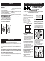
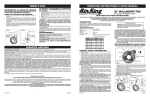
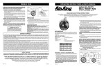
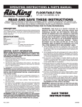
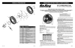
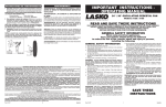
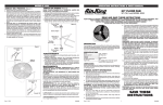
OPERATING INSTRUCTIONS & PARTS MANUAL
MODELO 9020
ATENCIÓN: EL CABLE DE APOYO SECUNDARIO
SUMINISTRADO DEBE UTILIZARSE CUANDO
QUIERA QUE EL VENTILADOR SEA MONTADO POR
LO ALTO, PARA MAYOR SEGURIDAD.
ADVERTENCIA: EL USO DEL CABLE DE SOPORTE SECUNDARIO NO
GARANTIZA LA PROTECCIÓN CONTRA LESIONES PERSONALES; EL
MONTAJE TANTO DEL CIRCULADOR COMO DEL CABLE PODRÍA FALLAR SI SE LO SOMETE A ABUSOS, NEGLIGENCIA O INSTALACIÓN NO
APROPIADA.
20" (50.8 cm) MODEL 9020
OPERACIÓN
CABLE DE APOYO SECUNDARIO
1.Conecte el cable y seleccione la velocidad de funcionamiento deseada
con el cordón accionador.
2. ADVERTENCIA: Este ventilador debe ser usa do solmente en unambiente
limpio y seco. Si producto esta montado de alguna otra manera espec´ifica
que indica la hoja de instrucción, purdiera anularse y no tener valor la garantia del fabricante
1. Entrelazar el cabo del Cable alrededor de los Alambres de Diámetro
Grande tanto por la Parte Delantera como por la Parte Trasera de la
Defensa del Ventilator (Figura 4)
2. Fijar la Mordaza del Cable de manera que la "U" del lado del cabo del
bucle quede con cabo de 1 a 2 pulgadas aproximadamente. Apretar las
Tuercas de la Mordaza. Hay que asegurarse de que ninguna parte del
Cable estorbe a la Paleta. (Figura 4)
3. Enroscar el otra cabo del Cable alrededor de una viga o armazón segura
de la edificación, o de otro soporte cercano al Ventilador. (Figura 5)
Recoger todo lo del cable que quede sobrando.
MANTENIMIENTO
ADVERTENCIA: DESCONECTE SIEMPRE EL CORDÓN ANTES DE INTENTAR REALIZAR CUALQUIER FUNCIÓN DE SERVICIO.
LIMPIEZA: Use un trapo y una solución de jabón suave, tal como detergente
líquido para lavar trastes.
ADVERTENCIA: No use gasolina, bencina, diluyente de pintura ni limpiadores fuertes en aerosol, ya que éstos dañarán el ventilador.
ALMACENAMIENTO: Cuando no lo utilice, mantenga el aparato en un
lugar limpio y seco.
ADVERTENCIA: UTILIZAR SÓLO LOS ELEMENTOS
METÁLICOS DE MONTAJE QUE SE RECOMIENDAN PARA
ESTE VENTILADOR.
4. Fijar la Mordaza de Cable restante como se indica en la parte 2. Hay
que recortar el exceso de cabo de manera que sólo queden de 1 a 2
pulgadas después de la Mordaza.
5. Revisar el Ensamblado para cerciorarse de que la Paleta esté libre de
toda obstrucción.
Figura 4
20" WALLMOUNT FAN
EL MOTOR HA SIDO PERMANENTEMENTE LUBRICADO.
READ AND SAVE THESE INSTRUCTIONS
READ CAREFULLY BEFORE ATTEMPTING TO ASSEMBLE, INSTALL, OPERATE OR MAINTAIN THE PRODUCT DESCRIBED. PROTECT YOURSELF AND OTHERS BY OBSERVING ALL SAFETY INFORMATION. FAILURE TO COMPLY WITH
INSTRUCTIONS COULD RESULT IN PERSONAL INJURY AND/OR PROPERTY DAMAGE!
RETAIN INSTRUCTIONS FOR FUTURE REFERENCE.
DESCRIPTION
C ommercial S tyle fan
The Air King® 20" (50.8 cm) wallmount fan features 3-speed pull
cord operation and a 3-paddle fan blade. This fan has a permanently
lubricated motor with a 9 ft. (2.74 m) 18/3 cord set and is constructed
of sturdy, powder coated steel.
WARNING : This fan should be us ed only in a
clean, dry environment. Mounting of this produc t
in any way other than s pec ified in the ins truction
sheet will null and void the manufacturers warranty.
SPECIFICATIONS
Motor ....................................... 120V, 50/60 Hz
Blade diameter........................ 20" (50.8 cm)
Speeds..................................... 3
Control..................................... Pull Cord
Air flow distribution................. 360°
Approvals................................. ETL Listed. Close mesh fan guard
................................................. meets OSHA requirements.
Figura 5
Alambres Grandes
de la Defense
Cable de
Soporte
Secundario
MODEL 9020
MED
LOW
5010
2.36
1041
1.46
167
55
3735
1.76
776
1.02
115
48
SPEEDHIGH
CFM M3/s RPM Amps Watts dB A
7510
3.54
1560
1.78
207
62
WARNING: BECAUSE OF SIZE AND WEIGHT OF THIS FAN, MAKE
SURE ALL PARTS ARE COMPLETELY ASSEMBLED ACCORDING
TO INSTRUCTIONS. FAILURE TO DO SO COULD RESULT IN FAN
COMING APART DURING OPERATION AND/OR PERSONAL INJURY.
WALL/CEILING BRACKET INSTALLATION
NOTE: ALWAYS INSTALL THE BRACKET TO A MINIMUM OF 2 X 4 STUDDING.
1. Lay Fan Head on flat surface, so the front side is facing down.
Loosely attach one Grill Knob and one Rubber Spacer to the Head
Assembly. Attach the other Grill Knob and Rubber Spacer to the
Head Assembly and FIRMLY tighten. Return to the first Grill Knob
and FIRMLY tighten. (Figure 1)
Yoke
Grill Knob
GENERAL SAFETY INFORMATION
Algunos estados y provincias no permiten limitaciones sobre la duración de una garantía implícita, o sobre la exclusión o limitación
de los daños incidentales o por consecuencia, por lo tanto dichas exclusiones o limitaciones podrían no aplicarse en su caso.  Esta
garantía le otorga a usted derechos legales específicos.  Usted también podría tener otros derechos que varían de estado en estado y de
provincia en provincia.
Se requiere prueba de compra antes que se acepte un reclamo bajo garantía.
Rev. A 7/12
4
2084805
Rev. A 7/12
Rubber Spacer
Rubber Spacer
Figure 1
2. Locate the wall or ceiling stud nearest to the desired Fan location.
Following the proper mounting diagram, attach the Bracket to
the stud using three (3) 5/16" diameter x 2" long Lag Screws (Not
Supplied) or appropriately sized Bolts and Nuts if attaching to "I"
beams.
Wall Mount Assembly(Figure 2)
Ceiling Mount Assembly(Figure 3)
3. Insert Bolt through Yoke, Bracket, Pivot Hole, Flatwasher, and into
Locknut. (Figure 2) or (Figure 3)
4. While holding Fan in the desired position, firmly tighten the 7/16"
Bolt.
Figure 2 (Wall Mount Assembly)
Nut
Flatwasher
Pivot
Hole
Bracket
Wall
GARANTÍA LIMITADA
QUÉ CUBRE ESTA GARANTÍAS:  Este producto está garantizado contra defectos de mano de obra y/o materiales.
CUÁNTO DURA ESTA GARANTÍA:  Esta garantía se extiende únicamente al comprador original del producto y dura un (1) año a partir de la fecha
original de compra o hasta que el comprador original del producto venda o transfiera el producto, cualesquiera de ambas que ocurriera en primer lugar.
QUÉ HARÁ AIR KING:  Durante el período de garantía, Air King, a opción propia, reparará o reemplazará cualquier parte o partes que demuestren
ser defectuosas o reemplazará el producto completo por el mismo modelo u otro comparable.
QUÉ NO CUBRE ESTA GARANTÍA:  Esta garantía no tiene validez si el producto fue dañado o falló debido a un accidente, manipulación u
operación inadecuadas, daño en el envío, abuso, mal uso, reparaciones no autorizadas hechas o el intento de hacerlas. Esta garantía no cubre los
costos de envío para la devolución de productos a Air King para su reparación o reemplazo.  Air King abonará los cargos de envío de devolución a
Air King con posterioridad a las reparaciones o el reemplazo bajo garantía.
CUALESQUIERA Y TODAS LAS GARANTÍAS, EXPLÍCITAS O IMPLÍCITAS (INCLUYENDO, SIN LIMITACIÓN, CUALESQUIERA GARANTÍA IMPLÍCITA
DE COMERCIABILIDAD), DURAN UN AÑO A PARTIR DE LA FECHA ORIGINAL DE COMPRA O HASTA QUE EL COMPRADOR ORIGINAL DEL
PRODUCTO VENDA O TRANSFIERA EL PRODUCTO, CUALESQUIERA DE AMBAS QUE OCURRIERA EN PRIMER LUGAR Y EN NINGÚN CASO
LA RESPONSABILIDAD DE AIR KING BAJO CUALQUIER GARANTÍA EXPLÍCITA O IMPLÍCITA INCLUIRÁ (I) DAÑOS INCIDENTALES O POR
CONSECUENCIA POR CUALQUIER CAUSA QUE FUERE, O (II) REEMPLAZO O REPARACIÓN DE CUALESQUIERA FUSIBLES HOGAREÑOS,
CORTA-CIRCUITOS O TOMACORRIENTES.  INDEPENDIENTEMENTE DE CUALQUIER DECLARACIÓN CONTRARIA, EN NINGÚN CASO LA
RESPONSABILIDAD DE AIR KING BAJO CUALQUIER GARANTÍA EXPLÍCITA O IMPLÍCITA PODRÁ EXCEDER EL PRECIO DE COMPRA DEL
PRODUCTO Y DICHA RESPONSABILIDAD TERMINARÁ AL VENCIMIENTO DEL PERÍODO DE GARANTÍA.
Grill Knob
1. Make certain that the power source conforms to the electrical
requirements of the fan.
2. The power cord is equipped with a three-prong grounded plug that
must be inserted into a matching receptacle. Under no circumstances
must the grounding prong be cut off the plug. Where a two-prong
wall receptacle is encountered, it must be replaced with a properly
grounded three-prong receptacle installed in accordance with the
National Electrical Code (NEC) and all applicable local codes and
ordinances. This work must be done only by a qualified electrician,
using copper wire only.
WARNING: USE OF A THREE-PRONG TO TWO-PRONG ADAPTER
IS NOT RECOMMENDED. IMPROPER CONNECTION MAY CREATE
THE RISK OF ELECTROCUTION. USE OF SUCH ADAPTERS IS NOT
PERMITTED IN CANADA.
3. Where possible, avoid the use of extension cords. If they must be
used, minimize the risk of overheating by ensuring that they are UL
listed and of the proper gage and length. Never use a single extension cord to operate more than one fan.
4. Do not insert fingers or foreign objects into the fan. Do not block or
tamper with the fan in any manner while it is in operation. Do not
touch the fan while in operation or just after it has been turned off,
as some parts may be hot enough to cause injury.
5. Unplug power cord before installing or servicing the fan.
WARNING: DO NOT DEPEND UPON THE ON-OFF SWITCH AS THE
SOLE MEANS OF DISCONNECTING POWER WHEN INSTALLING OR
SERVICING THE FAN. ALWAYS UNPLUG THE POWER CORD.
6. This fan is intended for general use ONLY. It must NOT be used in
potentially dangerous locations such as flammable, explosive, chemicalladen or wet atmospheres.
WARNING: TO REDUCE THE RISK OF FIRE OR ELECTRIC SHOCK, DO
NOT USE THIS FAN WITH ANY SOLID STATE SPEED CONTROL DEVICE.
7. DO NOT use fan in a window. Rain may create an electrical hazard.
8. Completely reassemble fan, according to instructions before
reconnecting to power supply.
Figure 3 (Ceiling Mount Assembly)
Ceiling Stud
Nut
Bracket
Pivot
Hole
Bolt
Bolt
Flatwasher
Yoke
Yoke
Fan Head
1
Fan Head
2084805
MANUAL DE INSTRUCCIONES DE OPERACIÓN Y PARTES
MODEL 9020
OPERATION
CAUTION: THE SECONDARY SUPPORT CABLE
PROVIDED SHOULD BE USED ANYTIME THE
CIRCULATOR IS MOUNTED OVERHEAD FOR
ADDITION SAFETY.
2. WARNING: This fan should be used only in a clean, dry environment. Mounting of this product in any way other then specified in
the instruction sheet will null and void the manufacturers warranty.
SECONDARY SUPPORT CABLE
20" (50.8 cm) MODELO 9020
MAINTENANCE
1. Loop one end of Cable around the Large Diameter Wires of both the
Front and Rear Circulator Guard. (Figure 4)
2. Attach a Cable Clamp with the "U" on the tail side of the loop leaving
a tail approximately 1 to 2 inches. Tighten Clamp Nuts. Make sure no
part of the Cable interferes with the Blade. (Figure 4)
3. Wrap the other end of the Cable around a secure building joist, truss,
or other support near the Fan. (Figure 5) Take up excess slack in the
Cable.
WARNING: ALWAYS UNPLUG THE CORD BEFORE SERVICING.
CLEANING: Use a soft cloth and a mild soap solution such as liquid
dish washing detergent.
CAUTION: Do not use gasoline, benzine, thinner, harsh cleaners, etc.
which will damage the fan.
Dry all parts with a soft cloth completely before reconnecting to power
supply.
STORAGE: When not in use, keep unit in a clean dry place.
MOTOR IS PERMANENTLY LUBRICATED.
CAUTION: USE ONLY THE MOUNTING HARDWARE
WHICH IS RECOMMENDED FOR USE ON THIS FAN.
4. Attach the remaining Cable Clamp as indicated in Step 2. The excess
tail should be trimmed to extend 1 to 2 inches past the Clamp.
5. Check the Assembly to assure the Blade is free of all obstructions.
CAUTION: USE OF THE SECONDARY SUPPORT CABLE DOES NOT
GUARANTEE PROTECTION AGAINST INJURY OF PERSONS, MOUNTING OF BOTH THE CIRCULATOR AND CABLE COULD FAIL IF SUBJECTED TO ABUSE, NEGLECT OR IMPROPER INSTALLATION.
Figure 4
El VENTILADOR DE MONTAJE
EN PARED DE 20" (50.8 cm)
1. Plug in cord and select desired operating speed with pull cord.
LEA Y GUARDE ESTAS INSTRUCCIONES
LÉALAS CUIDADOSAMENTE ANTES DE INTENTAR ARMAR, INSTALAR, OPERAR O DAR MANTENIMIENTO AL PRODUCTO DESCRITO. PROTÉJASE A SÍ MISMO Y A LOS DEMÁS OBSERVANDO TODA LA INFORMACIÓN SOBRE SEGURIDAD. ¡NO SEGUIR LAS INSTRUCCIONES PODRÍA
RESULTAR EN LESIONES PERSONALES Y/O DAÑOS A LA PROPIEDAD!
GUARDE LAS INSTRUCCIONES PARA REFERENCIAS FUTURAS.
DESCRIPCIÓN
ADVERTENCIA
: E ste ventilador debe ser usa
do solamente en un ambiente limpio y seco. S i
produc to esta montado de alguna otra manera
espec´ifica que indica la hoja de instrucción, purdiera
anularse y no tener valor la garantia del fabricante.
ESPECIFICACIONES
ADVERTENCIA: DEBIDO AL TAMANO Y PESO DE ESTE VENTILADOR,
ASEGURESE DE QUE TODAS LAS PIEZAS ESTAN COMPLETAMENTE
MONTADAS DE ACUERDO CON LAS INSTRUCCIONES. UN FALLO PODRIA
CAUSAR LA DESUNION DE LAS PIEZAS DURANTE SU FUNCIONAMIENTO
Y/O DANOS PERSONALES.
Motor.................................................... 120V, 50/60Hz
Tarmano De Paletas............................ 20" (50.8 cm)
Velocidades......................................... 3
Control................................................. Conjuntor rotatorio
Distribución del lujo de aire................ 360°
Aprobaciones................ Catalogación ETL. El protector de malla cerrada
del ventilador satisface las normas OSHA.
Figure 5
MODELO Large
Guard Wires
Ventilador E s tilo Comercial
El ventilador montaje en pared Air King® 20" (50.8 cm) ofrece una operación
de accionado por un cordón de 3 velocidades y 3 paletas de ventilador.
Este ventilador dispone de un motor de lubricación permanente con un
cordón18/3 de 2.74 cm (9 pies) y está construido con acero pulverizado
muy resistente.
VELOC.ALTA
CFM M3/s RPM Amps Watts dB A
Secondary
Support
Cable
7510
3.54
1560
1.78
207
62
INSTALACIÓN DE MÉNSULA EN PAREDES / TECHOS
NOTA: SIEMPRE INSTALE LA MÉNSULA EN MONTANTES DE 2X4 COMO
MÍNIMO.
1. Ponga la Cabeza del Ventilador sobre una superficie plana de modo que
el frente esté hacia abajo. Coloque en forma aflojada una Perilla de la
Rejilla y un Espaciador de Caucho en el Conjunto de la Cabeza. Coloque
la otra Perilla de la Rejilla y el Espaciador de Caucho en el Conjunto
de la Cabeza y apriete FIRMEMENTE. Vuelva a la primera Perilla de la
Rejilla y apriete FIRMEMENTE. (Figura 1)
9020
MEDIA
BAJA
5010
2.36
1041
1.46
167
55
3735
1.76
776
1.02
115
48
Horqueta
Perilla de
la Rejilla
INFORMACIÓN GENERAL SOBRE SEGURIDAD
Rev. A 7/12
2
2084805
Rev. A 7/12
Perilla de
la Rejilla
Espaciador
de Caucho
Espaciador
de Caucho
Figura 1
2. Localice el montante de pared o techo más cercano a la ubicación deseada para el Ventilador. Siguiendo el diagrama de montaje apropiado,
una la Ménsula al montante, usando tres (3) Tornillos de Retraso de 5/16"
de diámetro x 2" de longitud (no proporcionados) o Pernos y Tuercas
de tamaño apropiado si se lo monta a vigas "I".
Conjunto de Montaje en la Pared(Figura 2)
Conjunto de Montaje en el Techo(Figura 3)
3. Inserte el Perno a través de la Horqueta, Soporte, Orificio de Giro,
Arandela Plana, y dentro de la Tuerca. (Figura 2) o (Figura 3)
4. Mientras sostiene el Ventilador en la posición deseada, apriete firmemente
el perno de 7/16".
Figura 2
(Conjunto de Montaje en la Pared)
Tuerca
Soporte
Arandela
Plana
Orificio
de Giro
Montante
de Pared
LIMITED WARRANTY
WHAT THIS WARRANTY COVERS:  This product is warranted against defects in workmanship and/or materials.
HOW LONG THIS WARRANTY LASTS:  This warranty extends only to the original purchaser of the product and lasts for one (1) year from the date
of original purchase or until the original purchaser of the product sells or transfers the product, whichever first occurs.
WHAT AIR KING WILL DO:  During the warranty period, Air King will, at its sole option, repair or replace any part or parts that prove to be defective
or replace the whole product with the same or comparable model.
WHAT THIS WARRANTY DOES NOT COVER:  This warranty does not apply if the product was damaged or failed because of accident, improper
handling or operation, shipping damage, abuse, misuse, unauthorized repairs made or attempted. This warranty does not cover shipping costs for
the return of products to Air King for repair or replacement.  Air King will pay return shipping charges from Air King following warranty repairs or
replacement.
ANY AND ALL WARRANTIES, EXPRESSED OR IMPLIED (INCLUDING, WITHOUT LIMITATION, ANY IMPLIED WARRANTY OF MERCHANTABILITY),
LAST ONE YEAR FROM THE DATE OF ORIGINAL PURCHASE OR UNTIL THE ORIGINAL PURCHASER OF THE PRODUCT SELLS OR TRANSFERS
THE PRODUCT, WHICHEVER FIRST OCCURS AND IN NO EVENT SHALL AIR KING'S LIABILITY UNDER ANY EXPRESS OR IMPLIED WARRANTY
INCLUDE (I) INCIDENTAL OR CONSEQUENTIAL DAMAGES FROM ANY CAUSE WHATSOEVER, OR (II) REPLACMENT OR REPAIR OF ANY
HOUSE FUSES, CIRCUIT BREAKERS OR RECEPTACLES.  NOTWITHSTANDING ANYTHING TO THE CONTRARY, IN NO EVENT SHALL AIR
KING'S LIABILITY UNDER ANY EXPRESS OR IMPLIED WARRANTY EXCEED THE PURCHASE PRICE OF THE PRODUCT AND ANY SUCH
LIABILITY SHALL TERMINATE UPON THE EXPIRATION OF THE WARRANTY PERIOD.
Some states and provinces do not allow limitations on how long an implied warranty lasts, or the exclusion or limitation of incidental or consequential
damages, so these exclusions or limitations may not apply to you.  This warranty gives you specific legal rights. You may also have other rights
which vary from state to state and province to province.
Proof of purchase is required before a warranty claim will be accepted.
1. Cerciórese de que la fuente de electricidad se adapte a los requerimientos
eléctricos del ventilador.
2. El cordón eléctrico está equipado con una clavija a tierra de tres espigas
que tiene que ser enchufada a un receptáculo del mismo diseño. Bajo
ninguna circunstancia deberá cortarse la espiga a tierra de la clavija. De
existir un receptáculo de pared de dos espigas, deberá reemplazarse
por uno de tres espigas debidamente puesto a tierra e instalado de conformidad con el Código Nacional de Electricidad y todos los códigos y
ordenanzas locales aplicables. El trabajo deberá hacerlo un electricista
calificado, utilizando exclusivamente alambre de cobre.
ADVERTENCIA: NO SE RECOMIENDA EL USO DE UN ADAPTADOR DE
TRES A DOS ESPIGAS. LA CONEXIÓN INDEBIDA PODRÍA CREAR EL
RIESGO DE SER ELECTROCUTADO. EL USO DE TALES ADAPTADORES
NO ESTÁ PERMITIDO EN CANADÁ.
3. Siempre que sea posible, evite el uso de extensiones eléctricas. Si tienen
que usarse, minimice el riesgo de sobrecalentamiento asegurándose de
que sean de catalogación UL y del calibre y la longitud adecuadas. Nunca
use una sola extensión para operar más de un ventilador.
4. No introduzca los dedos ni objetos extraños en el ventilador. No obstruya
ni manipule indebidamente el ventilador mientras esté en operación.
No toque el ventilador mientras esté en operación ni inmediatamente
después de haberlo apagado, ya que ciertas partes podrían estar lo
suficientemente calientes como para causar una lesión.
5. Desenchufe el cordón eléctrico antes de instalar o dar servicio al ventilador.
ADVERTENCIA: NO DEPENDA DEL INTERRUPTOR DE ENCENDIDO Y
APAGADO COMO EL ÚNICO MEDIO PARA INTERRUMPIR LA ALIMENTACIÓN ELÉCTRICA CUANDO INSTALE O DÉ SERVICIO AL VENTILADOR.
SIEMPRE DESENCHUFE EL CORDÓN ELÉCTRICO.
6. Este ventilador es para uso general EXCLUSIVAMENTE. NO deberá usarse en localidades potencialmente peligrosas tales como atmósferas
inflamables, explosivas, cargadas de gases o húmedas.
ADVERTENCIA: PARA REDUCIR EL RIESGO DE INCENDIOS O DESCARGAS
ELÉCTRICAS, NO USE ESTE VENTILADOR CON NINGÚN DISPOSITIVO
DE CONTROL DE VELOCIDAD DE ESTADO SÓLIDO.
7. NO utilice el ventilador en una ventana, ya que la lluvia podría crear un
peligro eléctrico.
8. Vuelva a armar completamente el ventilador, de acuerdo con las instrucciones, antes de volver a conectarlo a la alimentación eléctrica.
(Conjunto de Montaje en la Pared)
Montante de
Techo
Tuerca
Soporte
Orificio
de Giro
Perno
Horqueta
Cabeza
de
Ventilador
3
Figura 3
Perno
Cabeza
de
Ventilador
Arandela
Plana
Horqueta
2084805