1
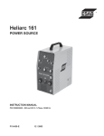
ARISTODRIVE 4-30 & 4-48HD
WIRE FEEDER
INSTRUCTION MANUAL
ESAB ITEM NO. 0558003275, AristoDrive 4-48
ESAB ITEM NO. 0558003276, AristoDrive 4-30
Revision B
0558003750
10 / 2003
BE SURE THIS INFORMATION REACHES THE OPERATOR
These INSTRUCTIONS are for experienced operators. If you are not fully familiar with
the principles of operation and safe practices for arc welding and cutting equipment,
we urge you to read our booklet, "Precautions and Safe Practices for Arc Welding,
Cutting, and Gouging," Form 52-529. Do NOT permit untrained persons to install,
operate, or maintain this equipment. Do NOT attempt to install or operate this
equipment until you have read and fully understand these instructions. If you do not
fully understand these instructions, contact your supplier for further information. Be
sure to read the Safety Precautions before installing or operating this equipment.
USER RESPONSIBILITY
This equipment will perform in conformity with the description thereof contained in this manual and
accompanying labels and/or inserts when installed, operated, maintained and repaired in accordance
with the instructions provided. This equipment must be checked periodically. Malfunctioning or
poorly maintained equipment should not be used. Parts that are broken, missing, worn, distorted
or contaminated should be replaced immediately. Should such repair or replacement become
necessary, the manufacturer recommends that a telephone or written request for service advice
be made to the Authorized Distributor from whom it was purchased.
This equipment or any of its parts should not be altered without the prior written approval of the
manufacturer. The user of this equipment shall have the sole responsibility for any malfunction
which results from improper use, faulty maintenance, damage, improper repair or alteration by
anyone other than the manufacturer or a service facility designated by the manufacturer.
Copies of this manual can be obtained by any of the following;
Contacting your local ESAB supplier.
Downloading a copy from the ESAB web site at
www.esabna.com
Sending a written request to
ESAB WELDING & CUTTING PRODUCTS
ATTN: LITERATURE DEPT.
411 S EBENEZER ROAD
FLORENCE SC 29501
2
TABLE OF CONTENTS
SECTION
PARAGRAPH
TITLE
PAGE
1
DESCRIPTION ...................................................................................................................... 11
2
INSTALLATION ..................................................................................................................... 19
3
OPERATION ......................................................................................................................... 23
4
TROUBLESHOOTING .......................................................................................................... 25
Schematic ............................................................................................................. 26
Wiring Diagram ..................................................................................................... 27
5
REPLACEMENT PARTS .......................................................................................................29
AristoDrive 4-30 .................................................................................................... 30
AristoDrive 4-48 .................................................................................................... 39
3
TABLE OF CONTENTS
4
SAFETY PRECAUTIONS
WARNING: These Safety Precautions are for
your protection. They summarize precautionary information from the references listed in
Additional Safety Information section. Before performing
any installation or operating procedures, be sure to read and
follow the safety precautions listed below as well as all other
manuals, material safety data sheets, labels, etc. Failure to
observe Safety Precautions can result in injury or death.
5. Do not use equipment beyond its ratings. For example,
overloaded welding cable can overheat and create a fire
hazard.
6. After completing operations, inspect the work area to
make certain there are no hot sparks or hot metal which
could cause a later fire. Use fire watchers when necessary.
7. For additional information, refer to NFPA Standard 51B,
"Fire Prevention in Use of Cutting and Welding Processes", available from the National Fire Protection Association, Batterymarch Park, Quincy, MA 02269.
PROTECT YOURSELF AND OTHERS -Some welding, cutting, and gouging
processes are noisy and require ear
protection. The arc, like the sun, emits
ultraviolet (UV) and other radiation and
can injure skin and eyes. Hot metal can cause burns.
Training in the proper use of the processes and equipment is essential to prevent accidents. Therefore:
ELECTRICAL SHOCK -- Contact with live
electrical parts and ground can cause
severe injury or death. DO NOT use AC
welding current in damp areas, if movement is confined, or if there is danger of
falling.
1. Always wear safety glasses with side shields in any work
area, even if welding helmets, face shields, and goggles
are also required.
2. Use a face shield fitted with the correct filter and cover
plates to protect your eyes, face, neck, and ears from
sparks and rays of the arc when operating or observing
operations. Warn bystanders not to watch the arc and not
to expose themselves to the rays of the electric-arc or hot
metal.
3. Wear flameproof gauntlet type gloves, heavy long-sleeve
shirt, cuffless trousers, high-topped shoes, and a welding helmet or cap for hair protection, to protect against
arc rays and hot sparks or hot metal. A flameproof apron
may also be desirable as protection against radiated
heat and sparks.
4. Hot sparks or metal can lodge in rolled up sleeves,
trouser cuffs, or pockets. Sleeves and collars should be
kept buttoned, and open pockets eliminated from the
front of clothing
5. Protect other personnel from arc rays and hot sparks with
a suitable non-flammable partition or curtains.
6. Use goggles over safety glasses when chipping slag or
grinding. Chipped slag may be hot and can fly far.
Bystanders should also wear goggles over
safety glasses.
1. Be sure the power source frame (chassis) is connected
to the ground system of the input power.
2. Connect the workpiece to a good electrical ground.
3. Connect the work cable to the workpiece. A poor or
missing connection can expose you or others to a fatal
shock.
4. Use well-maintained equipment. Replace worn or damaged cables.
5. Keep everything dry, including clothing, work area, cables,
torch/electrode holder, and power source.
6. Make sure that all parts of your body are insulated from
work and from ground.
7. Do not stand directly on metal or the earth while working
in tight quarters or a damp area; stand on dry boards or
an insulating platform and wear rubber-soled shoes.
8. Put on dry, hole-free gloves before turning on the power.
9. Turn off the power before removing your gloves.
10. Refer to ANSI/ASC Standard Z49.1 (listed on next page)
for specific grounding recommendations. Do not mistake
the work lead for a ground cable.
ELECTRIC AND MAGNETIC FIELDS —
May be dangerous. Electric current flowing through any conductor causes localized Electric and Magnetic Fields
(EMF). Welding and cutting current creates EMF around welding cables and
welding machines. Therefore:
FIRES AND EXPLOSIONS -- Heat from
flames and arcs can start fires. Hot slag
or sparks can also cause fires and explosions. Therefore:
1. Remove all combustible materials well away from the
work area or cover the materials with a protective nonflammable covering. Combustible materials include wood,
cloth, sawdust, liquid and gas fuels, solvents, paints and
coatings, paper, etc.
2. Hot sparks or hot metal can fall through cracks or
crevices in floors or wall openings and cause a hidden
smoldering fire or fires on the floor below. Make certain
that such openings are protected from hot sparks and
metal.“
3. Do not weld, cut or perform other hot work until the
workpiece has been completely cleaned so that there are
no substances on the workpiece which might produce
flammable or toxic vapors. Do not do hot work on closed
containers. They may explode.
4. Have fire extinguishing equipment handy for instant use,
such as a garden hose, water pail, sand bucket, or
portable fire extinguisher. Be sure you are trained in its
use.
1. Welders having pacemakers should consult their physician before welding. EMF may interfere with some pacemakers.
2. Exposure to EMF may have other health effects which are
unknown.
3. Welders should use the following procedures to minimize
exposure to EMF:
A. Route the electrode and work cables together. Secure
them with tape when possible.
B. Never coil the torch or work cable around your body.
C. Do not place your body between the torch and work
cables. Route cables on the same side of your body.
D. Connect the work cable to the workpiece as close as
possible to the area being welded.
E. Keep welding power source and cables as far away
from your body as possible.
5
SAFETY PRECAUTIONS
EQUIPMENT MAINTENANCE -- Faulty or
improperly maintained equipment can
cause injury or death. Therefore:
FUMES AND GASES -- Fumes and
gases, can cause discomfort or harm,
particularly in confined spaces. Do
not breathe fumes and gases. Shielding gases can cause asphyxiation.
Therefore:
1. Always have qualified personnel perform the installation,
troubleshooting, and maintenance work. Do not perform
any electrical work unless you are qualified to perform
such work.
2. Before performing any maintenance work inside a power
source, disconnect the power source from the incoming
electrical power.
3. Maintain cables, grounding wire, connections, power
cord, and power supply in safe working order. Do not
operate any equipment in faulty condition.
4. Do not abuse any equipment or accessories. Keep
equipment away from heat sources such as furnaces,
wet conditions such as water puddles, oil or grease,
corrosive atmospheres and inclement weather.
5. Keep all safety devices and cabinet covers in position
and in good repair.
6. Use equipment only for its intended purpose. Do not
modify it in any manner.
1. Always provide adequate ventilation in the work area by
natural or mechanical means. Do not weld, cut, or gouge
on materials such as galvanized steel, stainless steel,
copper, zinc, lead, beryllium, or cadmium unless positive
mechanical ventilation is provided. Do not breathe fumes
from these materials.
2. Do not operate near degreasing and spraying operations. The heat or arc rays can react with chlorinated
hydrocarbon vapors to form phosgene, a highly toxic
gas, and other irritant gases.
3. If you develop momentary eye, nose, or throat irritation
while operating, this is an indication that ventilation is not
adequate. Stop work and take necessary steps to improve ventilation in the work area. Do not continue to
operate if physical discomfort persists.
4. Refer to ANSI/ASC Standard Z49.1 (see listing below)
for specific ventilation recommendations.
5. WARNING: This product, when used for welding or
cutting, produces fumes or gases which
contain chemicals known to the State of
California to cause birth defects and, in
some cases, cancer. (California Health &
Safety Code §25249.5 et seq.)
ADDITIONAL SAFETY INFORMATION -- For
more information on safe practices for electric arc welding and cutting equipment, ask
your supplier for a copy of "Precautions and
Safe Practices for Arc Welding, Cutting and
Gouging", Form 52-529.
The following publications, which are available from the
American Welding Society, 550 N.W. LeJuene Road, Miami, FL 33126, are recommended to you:
1. ANSI/ASC Z49.1 - "Safety in Welding and Cutting"
2. AWS C5.1 - "Recommended Practices for Plasma Arc
Welding"
3. AWS C5.2 - "Recommended Practices for Plasma Arc
Cutting"
4. AWS C5.3 - "Recommended Practices for Air Carbon Arc
Gouging and Cutting"
5. AWS C5.5 - "Recommended Practices for Gas Tungsten
Arc Welding“
6. AWS C5.6 - "Recommended Practices for Gas Metal Arc
Welding"“
7. AWS SP - "Safe Practices" - Reprint, Welding Handbook.
8. ANSI/AWS F4.1, "Recommended Safe Practices for
Welding and Cutting of Containers That Have Held
Hazardous Substances."
CYLINDER HANDLING -- Cylinders, if
mishandled, can rupture and violently
release gas. Sudden rupture of cylinder, valve, or relief device can injure or
kill. Therefore:
1. Use the proper gas for the process and use the proper
pressure reducing regulator designed to operate from
the compressed gas cylinder. Do not use adaptors.
Maintain hoses and fittings in good condition. Follow
manufacturer's operating instructions for mounting regulator to a compressed gas cylinder.
2. Always secure cylinders in an upright position by chain or
strap to suitable hand trucks, undercarriages, benches,
walls, post, or racks. Never secure cylinders to work
tables or fixtures where they may become part of an
electrical circuit.
3. When not in use, keep cylinder valves closed. Have valve
protection cap in place if regulator is not connected.
Secure and move cylinders by using suitable hand trucks.
Avoid rough handling of cylinders.
4. Locate cylinders away from heat, sparks, and flames.
Never strike an arc on a cylinder.
5. For additional information, refer to CGA Standard P-1,
"Precautions for Safe Handling of Compressed Gases in
Cylinders", which is available from Compressed Gas
Association, 1235 Jefferson Davis Highway, Arlington,
VA 22202.
MEANING OF SYMBOLS - As used throughout this manual: Means Attention! Be Alert!
Your safety is involved.
Means immediate hazards which, if
not avoided, will result in immediate,
serious personal injury or loss of life.
Means potential hazards which could
result in personal injury or loss of life.
Means hazards which could result in
minor personal injury.
6
PRECAUCION DE SEGURIDAD
el calor causado por cable sobrecarga en los cables de soldar
pueden ocasionar un fuego.
6. Después de termirar la operación del equipo, inspeccione el área
de trabajo para cerciorarse de que las chispas o metal caliente
ocasionen un fuego más tarde. Tenga personal asignado para
vigilar si es necesario.
7. Para información adicional , haga referencia a la publicación
NFPA Standard 51B, "Fire Prevention in Use of Cutting and
Welding Processes", disponible a través de la National Fire
Protection Association, Batterymarch Park, Quincy, MA 02269.
ADVERTENCIA: Estas Precauciones de
Seguridad son para su protección. Ellas hacen
resumen de información proveniente de las referencias listadas en
la sección "Información Adicional Sobre La Seguridad". Antes de
hacer cualquier instalación o procedimiento de operación , asegúrese
de leer y seguir las precauciones de seguridad listadas a continuación
así como también todo manual, hoja de datos de seguridad del
material, calcomanias, etc. El no observar las Precauciones de
Seguridad puede resultar en daño a la persona o muerte.
PROTEJASE USTED Y A LOS DEMAS-Algunos procesos de soldadura, corte y
ranurado son ruidosos y requiren protección
para los oídos. El arco, como el sol , emite
rayos ultravioleta (UV) y otras radiaciones
que pueden dañar la piel y los ojos. El metal caliente causa
quemaduras. EL entrenamiento en el uso propio de los equipos
y sus procesos es esencial para prevenir accidentes. Por lo
tanto:
CHOQUE
1. Asegúrese de que el chasis de la fuente de poder esté conectado
1. Utilice gafas de seguridad con protección a los lados siempre
2.
3.
4.
5.
6.
a tierra através del sistema de electricidad primario.
2. Conecte la pieza de trabajo a un buen sistema de tierra física.
3. Conecte el cable de retorno a la pieza de trabajo. Cables y
conductores expuestos o con malas conexiones pueden exponer
al operador u otras personas a un choque eléctrico fatal.
4. Use el equipo solamente si está en buenas condiciones.
Reemplaze cables rotos, dañados o con conductores expuestos.
5. Mantenga todo seco, incluyendo su ropa, el área de trabajo, los
cables, antorchas, pinza del electrodo, y la fuente de poder.
6. Asegúrese que todas las partes de su cuerpo están insuladas
de ambos, la pieza de trabajo y tierra.
7. No se pare directamente sobre metal o tierra mientras trabaja en
lugares estrechos o áreas húmedas; trabaje sobre un pedazo de
madera seco o una plataforma insulada y use zapatos con suela
de goma.
8. Use guantes secos y sin agujeros antes de energizar el equipo.
9. Apage el equipo antes de quitarse sus guantes.
10. Use como referencia la publicación ANSI/ASC Standard Z49.1
(listado en la próxima página) para recomendaciones específicas
de como conectar el equipo a tierra. No confunda el cable de
soldar a la pieza de trabajo con el cable a tierra.
que esté en el área de trabajo, aún cuando esté usando careta
de soldar, protector para su cara u otro tipo de protección.
Use una careta que tenga el filtro correcto y lente para proteger
sus ojos, cara, cuello, y oídos de las chispas y rayos del arco
cuando se esté operando y observando las operaciones. Alerte
a todas las personas cercanas de no mirar el arco y no exponerse
a los rayos del arco eléctrico o el metal fundido.
Use guantes de cuero a prueba de fuego, camisa pesada de
mangas largas, pantalón de ruedo liso, zapato alto al tobillo, y
careta de soldar con capucha para el pelo, para proteger el
cuerpo de los rayos y chispas calientes provenientes del metal
fundido. En ocaciones un delantal a prueba de fuego es
necesario para protegerse del calor radiado y las chispas.
Chispas y partículas de metal caliente puede alojarse en las
mangas enrolladas de la camisa , el ruedo del pantalón o los
bolsillos. Mangas y cuellos deberán mantenerse abotonados,
bolsillos al frente de la camisa deberán ser cerrados o eliminados.
Proteja a otras personas de los rayos del arco y chispas calientes
con una cortina adecuada no-flamable como división.
Use careta protectora además de sus gafas de seguridad cuando
esté removiendo escoria o puliendo. La escoria puede estar
caliente y desprenderse con velocidad. Personas cercanas
deberán usar gafas de seguridad y careta protectora.
CAMPOS ELECTRICOS Y MAGNETICOS - Son peligrosos.
La corriente eléctrica fluye através de
cualquier conductor causando a nivel local Campos Eléctricos y Magnéticos
(EMF). Las corrientes en el área de corte
y soldadura, crean EMF alrrededor de los
cables de soldar y las maquinas. Por lo
tanto:
1. Soldadores u Operadores que use marca-
FUEGO Y EXPLOSIONES -- El calor de
las flamas y el arco pueden ocacionar
fuegos. Escoria caliente y las chispas
pueden causar fuegos y explosiones.
Por lo tanto:
1. Remueva todo material combustible lejos del área de trabajo o
2.
3.
4.
5.
cubra los materiales con una cobija a prueba de fuego. Materiales
combustibles incluyen madera, ropa, líquidos y gases flamables,
solventes, pinturas, papel, etc.
Chispas y partículas de metal pueden introducirse en las grietas
y agujeros de pisos y paredes causando fuegos escondidos en
otros niveles o espacios. Asegúrese de que toda grieta y agujero
esté cubierto para proteger lugares adyacentes contra fuegos.
No corte, suelde o haga cualquier otro trabajo relacionado hasta
que la pieza de trabajo esté totalmente limpia y libre de
substancias que puedan producir gases inflamables o vapores
tóxicos. No trabaje dentro o fuera de contenedores o tanques
cerrados. Estos pueden explotar si contienen vapores inflamables.
Tenga siempre a la mano equipo extintor de fuego para uso
instantáneo, como por ejemplo una manguera con agua, cubeta
con agua, cubeta con arena, o extintor portátil. Asegúrese que
usted esta entrenado para su uso.
No use el equipo fuera de su rango de operación. Por ejemplo,
ELECTRICO -- El contacto con las partes
eléctricas energizadas y tierra puede
causar daño severo o muerte. NO use
soldadura de corriente alterna (AC) en
áreas húmedas, de movimiento confinado
en lugares estrechos o si hay
posibilidad de caer al suelo.
pasos para el corazón
deberán consultar a su médico antes
de soldar. El Campo
Electromagnético (EMF) puede interferir
con algunos marca-pasos.
2. Exponerse a campos electromagnéticos (EMF) puede causar
otros efectos de salud aún desconocidos.
3. Los soldadores deberán usar los siguientes procedimientos para
minimizar exponerse al EMF:
A. Mantenga el electrodo y el cable a la pieza de trabajo juntos,
hasta llegar a la pieza que usted quiere soldar. Asegúrelos uno
junto al otro con cinta adhesiva cuando sea posible.
B. Nunca envuelva los cables de soldar alrededor de su cuerpo.
C. Nunca ubique su cuerpo entre la antorcha y el cable, a la pieza
de trabajo. Mantega los cables a un sólo lado de su cuerpo.
D. Conecte el cable de trabajo a la pieza de trabajo lo más
cercano posible al área de la soldadura.
E. Mantenga la fuente de poder y los cables de soldar lo más lejos
posible de su cuerpo.
7
HUMO Y GASES -- El humo y los gases,
pueden causar malestar o daño,
particularmente en espacios sin
ventilación. No inhale el humo o gases.
El gas de protección puede causar falta
de oxígeno.
Por lo tanto:
1. Siempre provea ventilación adecuada en el área de
trabajo por medio natural o mecánico. No solde, corte, o
ranure materiales con hierro galvanizado, acero inoxidable,
cobre, zinc, plomo, berílio, o cadmio a menos que provea
ventilación mecánica positiva . No respire los gases
producidos por estos materiales.
2. No opere cerca de lugares donde se aplique substancias
químicas en aerosol. El calor de los rayos del arco pueden
reaccionar con los vapores de hidrocarburo clorinado para
formar un fosfógeno, o gas tóxico, y otros irritant es.
3. Si momentáneamente desarrolla inrritación de ojos, nariz
o garganta mientras est á operando, es indicación de que
la ventilación no es apropiada. Pare de trabajar y tome
las medidas necesarias para mejorar la ventilación en
el área de trabajo. No continúe operando si el malestar
físico persiste.
4. Haga referencia a la publicación ANSI/ASC Standard
Z49.1 (Vea la lista a continuación) para recomendaciones
específicas en la ventilación.
5. ADVERTENCIA-- Este producto cuando se utiliza para
soldaduras o cortes, produce humos
o gases, los cuales contienen
químicos conocidos por el Estado
de California de causar defectos en
el nacimiento, o en algunos casos,
Cancer. (California Health & Safety
Code §25249.5 et seq.)
MANEJO DE CILINDROS-- Los
cilindros, si no son manejados
correctamente, pueden romperse y
liberar violentamente gases. Rotura
repentina del cilindro, válvula, o
válvula de escape puede causar daño
o muerte. Por lo tanto:
1. Utilize el gas apropiado para el proceso y utilize un
regulador diseñado para operar y reducir la presión del
cilindro de gas . No utilice adaptadores. Mantenga las
mangueras y las conexiones en buenas condiciones.
Observe las instrucciones de operación del manufacturero
para montar el regulador en el cilindro de gas comprimido.
2. Asegure siempre los cilindros en posición vertical y
amárrelos con una correa o cadena adecuada
para
asegurar el cilindro al carro, transportes, tablilleros, paredes,
postes, o armazón. Nunca asegure los cilindros a la mesa
de trabajo o las piezas que son parte del circuito de
soldadura . Este puede ser parte del circuito elélectrico.
3. Cuando el cilindro no está en uso, mantenga la válvula del
cilindro cerrada. Ponga el capote de protección sobre la
válvula si el regulador no está conectado. Asegure y
mueva los cilindros utilizando un carro o transporte
adecuado. Evite el manejo brusco de los
8
MANTENIMIENTO DEL EQUIPO -- Equipo
defectuoso o mal mantenido puede causar
daño o muerte. Por lo tanto:
1. Siempre tenga personal cualificado para efectuar l
a
instalación, diagnóstico, y mantenimiento
del
equipo. No ejecute ningún trabajo eléctrico a menos
que usted esté cualificado para hacer el trabajo.
2. Antes de dar mantenimiento en el interior de la
fuente de poder, desconecte la fuente de poder del
suministro de electricidad primaria.
3. Mantenga los cables, cable a tierra, conexciones, cable
primario, y cualquier otra fuente de poder en buen
estado operacional. No opere ningún equipo en
malas condiciones.
4. No abuse del equipo y sus accesorios. Mantenga el
equipo lejos de cosas que generen calor como
hornos, también lugares húmedos como charcos de
agua , aceite o grasa, atmósferas corrosivas y las
inclemencias del tiempo.
5. Mantenga todos los artículos de seguridad y coverturas
del equipo en su posición y en buenas condiciones.
6. Use el equipo sólo para el propósito que fue diseñado.
No modifique el equipo en ninguna manera.
INFORMACION ADICIONAL DE SEGURIDAD -Para más información sobre las prácticas de
seguridad de los equipos de arco eléctrico para
soldar y cortar, pregunte a su suplidor por una
copia de "Precautions and Safe Practices for Arc
Welding, Cutting and Gouging-Form 52-529.
Las siguientes publicaciones, disponibles através de la
American Welding Society, 550 N.W. LeJuene Road, Miami,
FL 33126, son recomendadas para usted:
1. ANSI/ASC Z49.1 - "Safety in Welding and Cutting"
2. AWS C5.1 - "Recommended Practices for Plasma Arc
Welding"
3. AWS C5.2 - "Recommended Practices for Plasma Arc
Cutting"
4. AWS C5.3 - "Recommended Practices for Air Carbon Arc
Gouging and Cutting"
5. AWS C5.5 - "Recommended Practices for Gas Tungsten
Arc Welding“
6. AWS C5.6 - "Recommended Practices for Gas Metal Arc
Welding"“
7. AWS SP - "Safe Practices" - Reprint, Welding Handbook.
8. ANSI/AWS F4.1, "Recommended Safe Practices for Welding and Cutting of Containers That Have Held Hazardous
Substances."
SIGNIFICADO DE LOS SIMBOLOS -Según usted avanza en la lectura de
este folleto: Los Símbolos Significan
¡Atención! ¡Esté Alerta! Se trata de su
seguridad.
Significa riesgo inmediato que, de no ser
evadido, puede resultar inmediatamente
en serio daño personal o la muerte.
Significa el riesgo de un peligro potencial
que puede resultar en serio daño personal o la muerte.
Significa el posible riesgo que puede
resultar en menores daños a la persona.
PRÉCAUTIONS DE SÉCURITÉ
a. Éloigner suffisamment tous les matériaux combustibles
du secteur où l’on exécute des soudures ou des coupes
à l’arc, à moins de les recouvrir complètement d’une
bâche non-inflammable. Ce type de matériaux comprend
notamment le bois, les vêtements, la sciure, l’essence, le
kérosène, les peintures, les solvants, le gaz naturel,
l’acétylène, le propane et autres substances combustibles semblables.
b. Les étincelles ou les projections de métal incandescent
peuvent tomber dans des fissures du plancher ou dans
des ouvertures des murs et y déclencher une ignition
lente cachée. Veiller à protéger ces ouvertures des
étincelles et des projections de métal.
c. N’exécutez pas de soudures, de coupes, d’opérations de
gougeage ou autres travaux à chaud à la surface de
barils, bidons, réservoirs ou autres contenants usagés,
avant de les avoir nettoyés de toute trace de substance
susceptible de produire des vapeurs inflammables ou
toxiques.
d. En vue d’assurer la prévention des incendies, il convient
de disposer d’un matériel d’extinction prêt à servir
immédiatement, tel qu’un tuyau d’arrosage, un seau à
eau, un seau de sable ou un extincteur portatif.
e. Une fois le travail à l’arc terminé, inspectez le secteur de
façon à vous assurer qu’aucune étincelle ou projection de
métal incandescent ne risque de provoquer ultérieurement
un feu.
3. CHOC ÉLECTRIQUE-- Le gougeage à l’arc et à l’arc au
plasma exige l’emploi de tensions à vide relativement
importantes; or, celles-ci risquent de causer des
dommages corporels graves et même mortels en cas
d’utilisation inadéquate. La gravité du choc électrique
reçu dépend du chemin suivi par le courant à travers le
corps humain et de son intensité.
a. Ne laissez jamais de surfaces métalliques sous tension
venir au contact direct de la peau ou de vêtements
humides. Veillez à porter des gants bien secs.
b. Si vous devez effectuer un travail sur une surface
métallique ou dans un secteur humide, veillez à assu-rer
votre isolation corporelle en portant des gants secs et des
chaussures à semelles de caoutchouc et en vous tenant
sur une planche ou une plate-forme sèche.
c. Mettez toujours à la terre le poste de soudage/coupage
en le reliant par un câble à une bonne prise de terre.
d. N’utilisez jamais de câbles usés ou endommagés. Ne
surchargez jamais le câble. Utilisez toujours un
équipement correctement entretenu.
e. Mettez l’équipement hors tension lorsqu’il n’est pas en
service. une mise à la masse accidentelle peut en effet
provoquer une surchauffe de l’équipement et un danger
d’incendie. Ne pas enrouler ou passer le câble autour
d’une partie quelconque du corps.
f. Vérifiez si le câble de masse est bien relié à la pièce en un
point aussi proche que possible de la zone de travail. Le
branchement des câbles de masse à l’ossature du
bâtiment ou en un point éloigné de la zone de travail
augmente en effet le risque de passage d’un courant de
sortie par des chaînes de
AVERTISSEMENT: Ces règles de sécurité ont pour objet
d’ assurer votre protection. Veillez à lire et à observer les
précautions énoncées ci-dessous avant de monter l’
équipement ou de commercer à l’utiliser. Tout défaut
d’observation de ces précautions risque d’entraîner des
blessures graves ou mortelles.
1.
PROTECTION INDIVIDUELLE-- Les brûlures de la
peau et des yeux dues au rayonnement de l’arc
électrique ou du métal incandescent, lors du soudage
au plasma ou à l’électrode ou lors du gougeage à
l’arc, peuvent s’avérer plus graves que celles résultant
d’une exposition prolongée au soleil. Aussi convient-il
d’observer les précautions suivantes:
a. Portez un écran facial adéquat muni des plaques
protectrices et des verres filtrants appropriés afin de
vous protéger les yeux, le visage, le cou et les oreilles
des étincelles et du rayonnement de l’arc électrique
lorsque vous effectuez des soudures ou des coupes
ou lorsque vous en observez l’exécution.
AVERTISSEZ les personnes se trouvant à proximité de
façon à ce qu’elles ne regardent pas l’arc et à ce
qu’elles ne s’exposent pas à son rayonnement, ni à
celui du métal incandescent.
b. Portez des gants ignifugés à crispins, une tunique
épaisse à manches longues, des pantalons sans
rebord, des chaussures à embout d’acier et un casque
de soudage ou une calotte de protection, afin d’éviter
d’exposer la peau au rayonnement de l’arc électrique
ou du métal incandescent. ll est également souhaitable
d’utiliser un tablier ininflammable de façon à se protéger
des étincelles et du rayonnement thermique.
c. Les étincelles ou les projections de métal incandescent
risquent de se loger dans des manches retroussées,
des bords relevés de pantalons ou dans des poches.
Aussi convient-il de garder boutonnés le col et les
manches et de porter des vêtements sans poches à
l’avant.
d. Protégez des étincelles et du rayonnement de l’arc
électrique les autres personnes travaillant à proximité
à l’aide d’un écran ininflammable adéquat.
e. Ne jamais omettre de porter des lunettes de sécurité
lorsque vous vous trouvez dans un secteur où l’on
effectue des opérations de soudage ou de coupage à
l’arc. Utilisez des lunettes de sécurité à écrans ou
verres latéraux pour piquer ou meûler le laitier. Les
piquetures incandescentes de laitier peuvent être
projetées à des distances considérables. Les
personnes se trouvant à proximité doivent également
porter des lunettes de protection.
f. Le gougeage à l’arc et le soudage à l’arc au plasma
produisent un niveau de bruit extrêmement élevé (de
100 à 114 dB) et exigent par conséquent l’emploi de
dispositifs appropriés de protection auditive.
2 PRÉVENTION DES INCENDES-- Les projections de
laitier incandescent ou d’étincelles peuvent provoquer
de graves incendies au contact de matériaux combustibles solides, liquides ou gazeux. Aussi faut-il
observer les précautions suivantes:
9
PRÉCAUTIONS DE SÉCURITÉ
AVERTISSEMENT: Ces règles de sécurité ont pour objet
d’ assurer votre protection. Veillez à lire et à observer les
précautions énoncées ci-dessous avant de monter l’
équipement ou de commercer à l’utiliser. Tout défaut
d’observation de ces précautions risque d’entraîner des
blessures graves ou mortelles.
1.
PROTECTION INDIVIDUELLE-- Les brûlures de la
peau et des yeux dues au rayonnement de l’arc
électrique ou du métal incandescent, lors du soudage
au plasma ou à l’électrode ou lors du gougeage à
l’arc, peuvent s’avérer plus graves que celles résultant
d’une exposition prolongée au soleil. Aussi convient-il
d’observer les précautions suivantes:
a. Portez un écran facial adéquat muni des plaques
protectrices et des verres filtrants appropriés afin de
vous protéger les yeux, le visage, le cou et les oreilles
des étincelles et du rayonnement de l’arc électrique
lorsque vous effectuez des soudures ou des coupes
ou lorsque vous en observez l’exécution.
AVERTISSEZ les personnes se trouvant à proximité de
façon à ce qu’elles ne regardent pas l’arc et à ce
qu’elles ne s’exposent pas à son rayonnement, ni à
celui du métal incandescent.
b. Portez des gants ignifugés à crispins, une tunique
épaisse à manches longues, des pantalons sans
rebord, des chaussures à embout d’acier et un casque
de soudage ou une calotte de protection, afin d’éviter
d’exposer la peau au rayonnement de l’arc électrique
ou du métal incandescent. ll est également souhaitable
d’utiliser un tablier ininflammable de façon à se protéger
des étincelles et du rayonnement thermique.
c. Les étincelles ou les projections de métal incandescent
risquent de se loger dans des manches retroussées,
des bords relevés de pantalons ou dans des poches.
Aussi convient-il de garder boutonnés le col et les
manches et de porter des vêtements sans poches à
l’avant.
d. Protégez des étincelles et du rayonnement de l’arc
électrique les autres personnes travaillant à proximité
à l’aide d’un écran ininflammable adéquat.
e. Ne jamais omettre de porter des lunettes de sécurité
lorsque vous vous trouvez dans un secteur où l’on
effectue des opérations de soudage ou de coupage à
l’arc. Utilisez des lunettes de sécurité à écrans ou
verres latéraux pour piquer ou meûler le laitier. Les
piquetures incandescentes de laitier peuvent être
projetées à des distances considérables. Les
personnes se trouvant à proximité doivent également
porter des lunettes de protection.
f. Le gougeage à l’arc et le soudage à l’arc au plasma
produisent un niveau de bruit extrêmement élevé (de
100 à 114 dB) et exigent par conséquent l’emploi de
dispositifs appropriés de protection auditive.
2 PRÉVENTION DES INCENDES-- Les projections de
laitier incandescent ou d’étincelles peuvent provoquer
de graves incendies au contact de matériaux combustibles solides, liquides ou gazeux. Aussi faut-il
observer les précautions suivantes:
10
a. Éloigner suffisamment tous les matériaux combustibles
du secteur où l’on exécute des soudures ou des coupes
à l’arc, à moins de les recouvrir complètement d’une
bâche non-inflammable. Ce type de matériaux comprend
notamment le bois, les vêtements, la sciure, l’essence, le
kérosène, les peintures, les solvants, le gaz naturel,
l’acétylène, le propane et autres substances combustibles semblables.
b. Les étincelles ou les projections de métal incandescent
peuvent tomber dans des fissures du plancher ou dans
des ouvertures des murs et y déclencher une ignition
lente cachée. Veiller à protéger ces ouvertures des
étincelles et des projections de métal.
c. N’exécutez pas de soudures, de coupes, d’opérations de
gougeage ou autres travaux à chaud à la surface de
barils, bidons, réservoirs ou autres contenants usagés,
avant de les avoir nettoyés de toute trace de substance
susceptible de produire des vapeurs inflammables ou
toxiques.
d. En vue d’assurer la prévention des incendies, il convient
de disposer d’un matériel d’extinction prêt à servir
immédiatement, tel qu’un tuyau d’arrosage, un seau à
eau, un seau de sable ou un extincteur portatif.
e. Une fois le travail à l’arc terminé, inspectez le secteur de
façon à vous assurer qu’aucune étincelle ou projection de
métal incandescent ne risque de provoquer ultérieurement
un feu.
3. CHOC ÉLECTRIQUE-- Le gougeage à l’arc et à l’arc au
plasma exige l’emploi de tensions à vide relativement
importantes; or, celles-ci risquent de causer des
dommages corporels graves et même mortels en cas
d’utilisation inadéquate. La gravité du choc électrique
reçu dépend du chemin suivi par le courant à travers le
corps humain et de son intensité.
a. Ne laissez jamais de surfaces métalliques sous tension
venir au contact direct de la peau ou de vêtements
humides. Veillez à porter des gants bien secs.
b. Si vous devez effectuer un travail sur une surface
métallique ou dans un secteur humide, veillez à assu-rer
votre isolation corporelle en portant des gants secs et des
chaussures à semelles de caoutchouc et en vous tenant
sur une planche ou une plate-forme sèche.
c. Mettez toujours à la terre le poste de soudage/coupage
en le reliant par un câble à une bonne prise de terre.
d. N’utilisez jamais de câbles usés ou endommagés. Ne
surchargez jamais le câble. Utilisez toujours un
équipement correctement entretenu.
e. Mettez l’équipement hors tension lorsqu’il n’est pas en
service. une mise à la masse accidentelle peut en effet
provoquer une surchauffe de l’équipement et un danger
d’incendie. Ne pas enrouler ou passer le câble autour
d’une partie quelconque du corps.
f. Vérifiez si le câble de masse est bien relié à la pièce en un
point aussi proche que possible de la zone de travail. Le
branchement des câbles de masse à l’ossature du
bâtiment ou en un point éloigné de la zone de travail
augmente en effet le risque de passage d’un courant de
sortie par des chaînes de
SECTION 1
DESCRIPTION
AristoDrive 4TM-Wire Feeders
■
■
■
■
■
■
■
■
■
■
■
■
■
■
Modular MMC panel for easy function and
feature upgradability (MMC=Man/Machine
Communications) .
Use with AristoPower-460 Power Source
Heavy duty compact wire feed motor.
Quick release 4-roll drive assembly; no readjustment of pressure required when rethreading
wire.
Quick release “No Tools” feed roll system.
Driven upper and lower feed rolls for positive
feed force and maximum wire grip.
Presettable arc voltage and wire speed
All control circuits incorporated on one solidstate printed circuit board, mounted for easy
access and removal.
Slow run-in button sets the wire feed speed to
1/2 the preset until the arc is struck for
smoother arc starting.
Jog button for wire inching without energizing
the power source contactor.
Anti-stick wire burnback control for precise
adjustment of amount of wire burnback after
wire feed stops, to eliminate freezing of wire in
weld pool.
Low voltage circuit (12V) for gun trigger switch,
to assure operator safety.
NAS (#4 Tweco) gun adapter factory installed.
“Sure Start” wire conditioning to eliminate wire
balling and ensure good arc starting
AristoDrive 4-30
AristoDrive 4-48
Specifications:
AristoDrive 4-30
AristoDrive 4-48
Wire Feed Range:
Speed Range ........ 30-999 in/min (.8 - 25 m/min)
Wire Sizes:
Hard (V-Groove) ...... .023 - 1/16 in.(.6-1.6mm)
Cored (Knurled) ....... .035 - 5/64 in.(.9-2.0mm)
Soft (U-Groove) ....... .035 - 1/16 in.(.9-1.6mm)
Input power ................................................ 42 Vac / 60hz.
Drive Roll Diameter ................................................. 30mm
Dimensions:
Length ....................................... 22.5 in.(572mm)
Width ......................................... 10.5 in.(268mm)
Height ....................................... 16.5 in.(419mm)
Weight. ....................................... 45-lbs.(20.5Kg)
Wire Feed Range:
Speed Range ..... 30-800 in/min (.8 - 20.5 m/min)
Wire Sizes:
Hard (V-Groove) .... .035 - 1/16 in.(.9 - 1.6mm)
Tubular (Knurled) .. .035 - 1/8 in. (.9 - 3.2mm)
Soft (U-Groove) ..... .045 - 3/32 in.(.9 - 2.4mm)
Input Power ................................................ 42 Vac / 60hz.
Drive Roll Diameter ................................................. 48mm
Dimensions:
Length .......................................... 23 in.(584mm)
Width ......................................... 14.5 in.(368mm)
Height ....................................... 16.5 in.(419mm)
Weight ............................................ 53 lbs.(24Kg)
11
SECTION 1
DESCRIPTION
MMA-6 MMC (Man/Machine Communications)
Easy to set weld parameters for MIG, MIG Pulse, Stick or Gouging.
Choose synergic weld parameters from of 107 possibilities. Set
the wire feed speed and weld!
Internal Memory stores up to 10 different weld parameter setups. Recall parameters with a simple push of a button.
Programmable soft keys allow direct access to flexible functions,
such as hot start, crater fill, 2/4 stroke trigger, wire inch, gas purge,
etc.
Large display gives real time voltage, current, and wire feed speed
read-outs.
Preset inductance, gas pre & post flow, inch or metric units, auto
weld schedule select, arc force, burnback and more. Update and
change weld data using optional ESAT software for maximum
flexibility.
Options & Accessories
AristoDrive 4
Hanging Bail .................................................... 0558003047
Handle Kit ....................................................... 0558002356
Wheel Kit ................................................................... 34324
Swivel Post ................................................................ 36172
Marathon Pack Inlet Guide ............................. 0558002519
Requires ............................................................... 899F50
Counterbalance Mini-Boom ............................ 0458705881
Reel Assembly .......................................................... 34323
Spool Cover .................................................... 0558003047
Control Cable, 6.5ft.(2m) ................................. 0456527880
Control Cable, 260ft. (8m) ............................... 0456527881
Control Cable, 52ft. (16m) ............................... 0456527882
Control Cable, 82ft. (25m) ............................... 0456527883
Control Cable, 114ft. (35m) ............................. 0456527884
Hanging bail
Marathon Pack
Inlet Guide
Handle
Trigger Leads, ESAB Style
Control Cable
Trigger Lead, GunMaster 250 ......................... 0558001815
Trigger Lead, GunMaster 400 ............................... 2075216
12
SECTION 1
DESCRIPTION
1.0
SAFETY
Before the AristoDrive 4-30 or 4-48 wire feeder is put into operation, the safety
section at the front of this manual should be read completely. This will help
avoid possible injury due to misuse or improper installation.
The definitions relating to the:
safety notations are described at the end of the Safety Section in the front of this
manual — read them and their specific text references carefully.
1.1
DESCRIPTION AND SPECIFICATIONS
The AristoDrive 4-30 & 4-48 are heavy duty 4 roll drive 42 vac wire feeders
with the ability to meet immediate and long term welding requirements of any
weld shop. It's "Modular Design" technology permits simplicity and flexibility
without unnecessary configuration and installation complexity. The innovative
and "easy to use" MA-6 AristoDrive control panel (MMC or Man/Machine Communications) simplifies the functionality and features selection of the welding
system. The drive stand gears are totally enclosed for safety, dependable and
reliable operation.
The AristoDrive 4-48 wire feeder will handle the most demanding welding applications using short arc, spray and pulsed spray arc Mig (GMAW, GMAW-P
& MCAW) welding or cored wire (FCAW ) welding using the AristoPower 460
power source.
A. FEATURES:
• Modular MMC (Man/Machine Communications) panel for easy function
and feature selection
• Heavy duty compact wire feed motor
• AristoDrive 4-48 has a heavy duty drive stand and large 48 mm drive rolls
• AristoDrive 4-30 has a heavy duty drive stand with 30mm rolls.
• Quick release 4-roll drive assembly; no readjustment of pressure required
when rethreading wire.
• Quick change “No Tools” feed roll system
•
Driven upper and lower drive rolls for positive feed force and maximum
wire grip.
• All control circuits incorporated on one solid-state printed circuit board,
mounted for easy access and removal.
•
Gas purge switch for shield gas flowrate preset.
•
Slow run-in panel button sets the wire feed speed at 1/2 the preset until
the arc is struck for smoother arc starting.
• Jog panel button for wire inching without energizing power source contactor.
• 4-stroke, Hot Start and Craterfill panel buttons for easy feature selection.
• Low voltage circuit (12v) for gun trigger switch, to assure operator safety.
•
NAS (#4 Tweco) gun adapter
• All cable and hose connections are quickly detachable.
13
SECTION 1
DESCRIPTION
B. Specifications AristoDrive 4-30 & AristoDrive 4-48
(See page 10)
C. Modular MMC System
Introduction
The interchangeable control panels (MMC) are available in 4 different models
depending on the needs of the welding operator and the welding application.
The panels are designed for easily removal and replacement. The following
describes the functions and capability of each MMC panel.
MA-6 MMC MIG/STICK PANEL
The MA-6 MMC panel is a simple, intuitive yet feature rich control panel that
will meet the weld requirements of most Mig, Stick and Arc Gouging applications. The flow chart below summarizes the features available.
14
SECTION 1
DESCRIPTION
D. Front Panel Components
1. MA-6 MIG/STICK/GOUGING MMC PANEL
2. Power On/Off Switch
Controls the 42 vac power from the AristoPower 460 power source.
A two prong “twist to lock” receptacle used to connect the Mig gun
trigger circuit to the wire feeder.
3. NAS (#4 Tweco) Power Pin Mig gun connection
E. Rear Panel:
1. Control Cable Receptacle
Receptacle that accepts the 19 pin control interconnect cable between
the wire feeder and power source.
2. Shield Gas Connection
Connect the shielding gas hose from the regulator/flowmeter to this
fitting.
3. Circuit Breaker
Prevents damage to the Main control PC board caused by excessive
line current.
4. Power Connection Block
Insulated connection point for the welding cables from the secondary
side of the welding power source.
1.2
RECOMMENDED EQUIPMENT AND ACCESSORIES
A. Control Cable Assembly:
For connection of the AristoDrive 4-48 to ESAB power sources with a
12-pin receptacle, the following control cable assemblies are available:
6-foot (2 m)
- 0456 527 880
25-foot (8 m)
- 0456 527 881
50-foot (16 m) - 0456 527 882
80-foot (25 m) - 0456 527 883
C. Mig Welding Guns:
Gun Master 250 Gas Cooled
Gun Master 400 Gas Cooled
D. Mig Gun Adapters
Only Tweco #4 is supported
E. Feed Rolls and Outlet Guides:
The appropriate feed roll, outlet guide and center guide is required for
optimum wire feeding. See Table 2-1 & 2-2.
F.
Shielding Gas Regulator/Flowmeter:
R-33 FM 580 (Argon) - P/N 21557
R-33 FM 360 (CO2) - P/N 21558
R-5007 Argon/Helium/Nitrogen - P/N 998124
R-5008 CO2 - P/N 998125.
G. Gas Hoses:
Argon/Helium, Nitrogen - P/N 40V77 (12-1/2 ft.) or P/N 34V38 (25 ft.)
Heavy Duty - P/N 19416 (12-1/2 ft.)* or P/N 19415 (25 ft.)*
*
Must be used for CO 2 and can also be used for Argon/Helium/Nitrogen.
15
SECTION 1
DESCRIPTION
SPOOL/REEL
SPINDLE POST
MODULAR MMI
(MAN/MACHINE INTERFACE)
PANEL
WIRE FEED
SPEED AND
VOLTAGE*
HEAVY DUTY
30mm ROLL
ENCLOSED
DRIVE STAND
MIG TORCH
CONNECTOR
RECEPTACLE
POWER "ON/OFF"
SWITCH
MIG TORCH
TRIGGER
RECEPTACLE
REMOTE
RECEPTACLE
Figure 1-1. AristoDrive 4-30 Wire Feeder
SPOOL/REEL
SPINDLE POST
MODULAR MMI
(MAN/MACHINE INTERFACE)
PANEL
WIRE FEED
SPEED AND
VOLTAGE*
HEAVY DUTY
48mm ROLL
DRIVE STAND
MIG TORCH
CONNECTOR
RECEPTACLE
POWER "ON/OFF"
SWITCH
MIG TORCH
TRIGGER
RECEPTACLE
REMOTE
RECEPTACLE
Figure 1-2. AristoDrive 4-48 Wire Feeder
16
SECTION 1
DESCRIPTION
H. OPTIONAL ACCESSORIES
1. Lifting Bracket - Hanging Bail (P/N 0558003047):
Mounts at the top of the wire feeder spool support. Enables you to
mount the wire feeder overhead on a boom or trolley system.
2. Reel Assembly (P/N 34323):
Reel slips over spindle to allow use of coiled wire.
3. Swivel Post (P/N 36172):
Installs on power sources such as ESAB 353cv, 453cv MultiPower
460 and 460 Pulse, or 653cvcc and allows the wire feeder to swivel
freely.
4. Swivel Post w/Mounting Bracket (P/N 34075):
Attaches to inverter cart (P/N 31700) or other flat mounting surface
and allows the feeder to swivel freely
5. Handle Kit (P/N 0558002356)
Includes handle with rubber grip and mounting hardware.
NOTE
The Counterbalance Mini-Boom cannot be
used with 14" spools ofr 65 lb. coils.
6. Wheel Kit (P/N 34324))
Makes it easy to roll wire feeder around job site Cart includes base,
front swivel caster wheels, rear caster wheels and mounting hardware.
7. Spool Enclousure Kit (AristoDrive 4-30 Only P/N 0558002357)
Cover and enclosure provides protection for a 12" spool of wire
against dust and dirt.
8. Counterbalance Mini-Boom (P/N 0458705881)
Mounts to the power source swivel post and reduces wire feeding
problems caused by sharp bends in the gun liner and cables by
keeping the gun cable off the floor. Includes boom and mounting
hardware. (requires Swivel Post - P/N 36172)
9. Marathon Pack Inlet Guide for AristoDrive 4-30 (P/N
0558002354)
Allows the secure connection of a Marathon Pack conduit/liner to
the rear panel of the AristoDrive wire feeder.
Requires Quick Disconnect Adaptor Kit (QAC) ......... P/N 899F50
10. Marathon Pack Inlet Guide for AristoDrive 4-48 (P/N 0558002519)
Allows the secure connection of a Marathon Pack conduit/liner to
the rear panel of the AristoDrive wire feeder.
Requires Quick Disconnect Adaptor Kit (QAC) P/N 899F50
11. Heavy Duty Pressure Spring (P/N - 0558002142)
Recommended for the 4-48 Drivestands using solid wires of 1/16"
diameter and greater.
17
SECTION 1
DESCRIPTION
18
SECTION 2
INSTALLATION
PRESSURE
ADJUSTMENT
PRESSURE ROLL
BOGEY
CENTER GUIDE
UPPER ROLL
LOCKING KNOB
RETAINING KNOB
CENTER
GUIDE
GUN LOCKING
KNOB
INLET GUIDE
LOCKING KNOB
OUTLET
GUIDE
OUTLET GUIDE
LOCKING KNOB
INLET GUIDE
GEAR PIN
AXLE
LOWER ROLL
RETAINING NUTS
Figure 2-1 AristoDrive 4-30 Drive Stand
UPPER ROLL
RETAINING KNOB
PRESSURE
ADJUSTMENT
CENTER GUIDE
LOCKING KNOB
PRESSURE ROLL
ARMS
INLET
GUIDE
FEED ROLL
SHAFT
LOWER ROLL
RETAINING KNOB
Figure 2-2 AristoDrive 4-48 Drive Stand
19
SECTION 2
INSTALLATION
Table 2-1 - AristoDrive 4-30 Feed Roll Table
Table 2-2 - AristoDrive 4-48 Feed Roll Table
Wire Size
inch
Wire Size
Part
mm
Number
Solid Wire V Groove (4 req'd.)
.023
0558002235
.6mm
.030
.8mm
0558002236
.035/.040
.9/1.0mm
0558002237
.045
1.2mm
0558002238
.052
0558002239
1.4mm
1/16" (.062)
0558002240
1.6mm
Cored Wire Serrated (4 req'd.)
.035
058002227
1.0mm
.045
058002228
1.2mm
.052
058002229
1.4mm
1/16" (.062)
1.6mm
058002230
5/64 (.078)
2.0mm
058002231
3/32 (.093)
058002232
2.4mm
.109
058002233
2.8mm
.125
058002234
3.2mm
Aluminum U Grooved (4 req'd.)
.030
055800243
.8mm
.035/.040
055800244
.9/1.0mm
3/64 (.047)
1.2mm
055800245
1/16" (.062)
1.6mm
055800247
3/32 (.093)
055800248
2.4mm
Inlet Guide (1 req'd.)
All
0558002347
3.5mm
HD Brass
0558002517
3.5mm
Center Guides (1 req'd.)
.023-.045 Steel
0558002223
1.5mm
.052-.062 Steel
0558002224
2.0mm
5/64 (.078) Steel
0558002225
2.5mm
.093-.125 Steel
3.5mm
0558002226
.023-.045 Aluminum
1.5mm
0558002307
.047-.062 Aluminum
0558002308
2.0mm
3/32 (.093) Aluminum
0558002310
3.5mm
Outlet Guides (1 req'd.)
.023-.045 Steel
0558002215
1.5mm
.052-.062 Steel
0558002216
2.0mm
5/64 (.078) Steel
0558002217
3.0 mm
.093-.125 Steel
0558002218
3.5mm
.023-.045 Aluminum
1.5mm
0558002219
.047-.062 Aluminum
2.0mm
0558002220
3/32 (.093) Aluminum
0558002222
3.0mm
Wire Size
inch
Wire Size
Part
mm
Number
Solid Wire V Groove (4 req'd.)
0459052001
.023-.030
0.8-0.9
0458655001
0459052003
.035/.040-.045
0.9/1.0-1.2
0458655003
0459052013
.052-1/16
1.4-1.6
0458655013
Cored Wire Serrated (4 req'd.)
.035-.045
0.9-1.2
0558002352
.045-.052
1.2-1.4
37319
1/16-5/64
1.6-2.0
37320
Aluminum U Grooved (4 req'd.)
.035-3/64
0.9-1.2
36860
3/64-1/16
1.2-1.6
36861
Inlet Guide (1 req'd.)
All
3mm
0455049001
Center Guides (1 req'd.)
Steel
2mm
0455072001
Steel
3mm
0455072002
Aluminum
2mm
0456615001
Outlet Guides (1 req'd.)
Steel
1.5mm
0458690880
Steel
2mm
0458690881
Steel
3mm
0458690882
Aluminum
2mm
0458690883
20
SECTION 2
INSTALLATION
2.0
INSTALLATION
After checking to be sure you have all required components and accessories, proceed as follows:
A. HOSE AND ELECTRICAL CONNECTIONS
1. Connect shielding gas supply hose to the rear panel of the feeder.
2. Connect the 19-pin control cable between the AristoDrive rear panel
and power source wire feeder connection.
3. Connect suitably sized power cable between the power source and
the power block at the rear base of the feeder.
B. CENTER AND OUTLET GUIDES
1. Choose the correct type and size center and outlet guide for the
type of drive stand on the feeder. See Figure 2-1 or 2-2 and Table
2-1 or 2-2.
2. Insert the center guide into the drive stand center support between
the front and rear drive axles. Tighten the locking knob to secure in
place.
3. Insert the outlet guide tapered end first into the front of the Mig gun
adapter and secure with locking knob.
C. MIG GUN CONNECTIONS
Gun Master 250 and 400
1. Connect Mig Gun to feed roll accessory drive by loosening the
locking knob on the drive roll accessory gun adapter and insert the
gun power pin into the gun adaptor then tighten locking knob.
2. Connect the gun trigger twist lock plug into the mating receptacle
on the front panel of the AristoDrive feeder and lock by twisting 1/4
turn.
D. INSTALLING 4-30 FEED ROLL
Lower Feed Rolls
1. Release the tension lever on the pressure roll bogey and flip up to
access the drive rolls
2. Remove the lower feed roll retaining knobs.
3. Separate the feed roll from the gear pin axle and slip the new feed
roll on the gear shaft, engaging the gear pins.
4. Reinstall the feed roll retaining knobs.
Upper Feed Rolls
1. Release the tension lever on the pressure roll bogey and flip up to
access the drive rolls
2. Remove the upper feed roll retaining knobs by turning knob 1/4 turn
and pulling axle straight out.
3. Separate the feed roll from the gear pin axle and slip the new feed
roll on the gear shaft, engaging the gear pins.
4. Reinstall the feed roll retaining knob and axle.
21
SECTION 2
INSTALLATION
E. INSTALLING 4-48 FEED ROLLS
1. Release the tension levers on the pressure roll arms and flip outward
(away from the center of the drive stand) to lift the top rolls from the
bottom rolls.
2. Twist the feed roll retaining knobs so that the flutes align with the axle
pin.
3. Slip the feed roll on the axle and over the axle pins.
4. Twist the retaining knob 1/8 turn to lock the rolls in place.
F.
INSTALLING SPOOL OF WIRE (4-48)
1. Remove “S-pin” clip from spindle.
2. Position the spool of wire so that when it is placed on the spindle, wire
will be drawn to the feed roll from the bottom of the spool. The spool
should be held so that the index hole on the spool will engage the pin
on the spindle.
3. Slide the spool onto the spindle until it engages the spindle pin. Lock
in place with the S-pin clip.
4. Loosen the brake screw in the center of the spindle hub, then tighten
it just enough to prevent coasting of the spool when wire is drawn
from it. Too much pressure will load the wire feed motor unnecessarily. Too little pressure will permit the spool to overrun, causing the wire
to come loose and tangle.
5. Thread wire to gun as follows:
a. Round off the free end of the welding wire with a file.
b. Release the tension levers on the pressure roll arm assembly.
c. Thread the wire through the inlet guide, over the feedroll
grooves and into the outlet guide.
d. Close the pressure roll making sure the wire is seated in
both the top and bottom feed roll grooves.
e. Remove nozzle and contact tip from the gun. Turn on the
Power Source using the main power switch. Inch the wire,
using the AristoDrive jog switch, until the wire exits the front
end of gun. Thread the contact tip over the wire and tighten
into the tip adapter. Replace gun nozzle.
6. When wire coils are to be used, raise the spindle assembly to its highest mounting position in the spindle post. Mount the wire reel onto the
spindle as though it were a spool (see 1 and 3 above). Remove wing
nuts and cover plate from reel. Remove coil from its package, but do
not remove its binding wires or straps. Slide coil onto reel so that
wire will be drawn from bottom of coil (starting end for a coil is always
the outer end). Replace reel cover plate and wing nuts. Cut off coil tie
wires. Adjust brake screw and thread wire to the gun as covered in 4
and 5 above.
G. ADJUSTING THE PRESSURE ROLL ASSEMBLY
When a new wire size or type installed, set the pressure adjustment as follows:
1. Unscrew the pressure adjustment knob until the pressure knob is free.
2. Alternately press and release the gun trigger switch while slowly tightening the pressure adjusting knob until the wire begins to feed without
slipping. The pressure applied should be the minimum required to
provide positive, nonslip wire feed. Too little pressure will result in wire
slippage while excessive pressure will scar and deform the wire.
22
SECTION 3
OPERATION
3.0
ADJUSTMENTS AND OPERATION
A. CONTROL SETTINGS
1. Turn the AristoDrive POWER switch to the “ON” position then turn on
the AristoPower power source.
2. Set the weld process, wire type, wire size and shielding gas being
used on the MA-6 MMC panel. See the MA-6 Instruction manual for
more details and complete MA-6 operation.
3. Set the wire feed rate by adjusting the WIRE FEED SPEED control
knob on the MMC panel. The wire feed rate controls the weld current
furnished by the CV power source.
B. FEEDING WIRE
If wire has been threaded through gun and contact tip, simply operate the jog
button or cut off wire, as required, so that the wire extends about 1/2 in. beyond the end of the gun nozzle.
C. SHIELDING GAS FLOW RATE
Actuate the gas purge button on the MA-6 Panel and set gas flow rate at the
shielding gas regulator-flowmeter to 35 to 40 cfh. Maintain flow for at least 15
seconds to insure adequate purging of gas hose and gun. Preflow/postflow
times can be set under the SETTINGS menu on the MA-6 MMC panel.
D. SLOW INCH BUTTON
Press the SLOW INCH button if a slow run-in of the weld wire is desired. The
wire feed speed will then be at 1/2 the preset wire feed rate when the gun
trigger is pulled until the arc is struck. The wire speed will then increase to the
preset speed for welding. This functions gives smoother arc starting for some
weld applications.
E. MAKING THE WELD
Start to weld by pressing the gun trigger lever. This closes the welding contactor,
and starts gas flow and wire feed. When the welding wire touches the workpiece
an arc will be established. The trigger switch lever must be depressed for the
duration of the weld (unless the trigger latch option has been installed and set
in the trigger latch position). Welding action will be stopped and all services
discontinued when the trigger switch lever is released and returns to its original position. If the gun is withdrawn from the workpiece during welding, the arc
will be interrupted, but shielding gas flow and welding wire feed will continue
until the switch lever is released.
23
SECTION 3
OPERATION
3.1
OPERATING SEQUENCE
NORMAL
1 . Close gun trigger switch.
— Gas solenoid opens, weld contactor closes, wire feed motor runs at
preset wire feed speed, or slow inch, whichever has been selected.
2. Release gun trigger switch.
— Wire feed motor de-energized, brake circuit enabled.
— Anti-stick circuit energized.
— Weld contactor opens.
— Burnback circuit times out
(delay determined by setting of Burnback potentiometer).
— Gas solenoid valve closes.
24
SECTION 4
4.0
TROUBLESHOOTING
TROUBLESHOOTING
Table 4-1 AristoDrive 4-48 Troubleshooting Chart
Nothing works
Check if power source is energized
Check if AristoDrive
DuraDrive "Power" switch is in the "ON" position
Wire Feeder is "ON", motor does not run,
gas valve and welding power source
Check CB fuse on AristoDrive
DuraDrive Rear Panel
contactor do not energize
Check weld gun trigger plug connection
Wire feeds, shielding gas flows, but no
Check if power source has Open Circuit Voltage
power to electrode wire
Check if weld cables are connected
Check interconnect cable for continuity or loose connection
Motor runs slowly and/or gas solenoid
Check for 42 vac input voltage
valve
"chattering"
vale isis"chattering"
Welding wire feed cannot be shut OFF
Short in welding gun trigger leads.
and feeds continuously
or feeds erratically
Electrode wire stops of
Check weld gun trigger connection
during welding
Check weld gun trigger switch
Readjust spool spindle brake and pressure roll tension
Check for the correct size and type drive rolls for the electrode wire being used.
Clean or replace dirty or worn drive rolls.
Check for incorrect type or sized outlet and center guides
Check and/or replace the weld gun contact tip and/or liner if worn or damaged
Remove weld spatter and debris form weld gun nozzle and contact tip
Have an ESAB Authorized Repair station check the motor drive and control PCB.
A. MAINTENANCE
If this equipment does not operate properly, stop work immediately and
investigate the cause of the malfunction. Maintenance work must be performed by an experienced person, and electrical work by a trained electrician. Do not permit untrained persons to inspect, clean, or repair this
equipment. Use only recommended replacement parts.
B. GENERAL MAINTENANCE
Little maintenance is required to keep the wire feeder in top operating condition. It is important, however, that moving parts such as feed and pressure
rolls, wire feed motor, etc., be kept clean and free of dust or dirt. Cleaning is
best accomplished by regularly blowing off these parts with dry compressed
air. This should be done once for every eight hours of operating time, more
often if necessary.
25
0558003277-A
AristoDrive 4-30 and 4-48 Schematic Diagram
SECTION 4
TROUBLESHOOTING
26
0558003278
AristoDrive 4-30 and 4-48 Schematic Diagram
SECTION 4
TROUBLESHOOTING
27
SECTION 4
TROUBLESHOOTING
28
SECTION 5
REPLACEMENT PARTS
5.0 SPARE AND REPAIR PARTS
Replacement Parts are illustrated on the following pages. When ordering replacement parts, order by part number and part name, as illustrated on the
figure
Always provide the series or serial number of the unit on which the parts will
be used. The serial number is stamped on the unit nameplate.
5.1 ORDERING
To assure proper operation, it is recommended that only genuine ESAB parts
and products be used with this equipment. The use of non-ESAB parts may
void your warranty.
Replacement parts may be ordered from your ESAB distributor or from:
ESAB Welding & Cutting Products
Attn: Customer Service Dept.
P.O. Box 100545, 411 S. Ebenezer Road
Florence, SC 29501-0545
Be sure to indicate any special shipping instructions when ordering replacement parts.
To order parts by phone, contact ESAB at 1-843-664-5540. Orders may also
be faxed to 1-800-634-7548. Be sure to indicate any special shipping instructions when ordering replacement parts.
Refer to the Communication Guide located on the last page of this manual for
a list of customer service phone numbers.
29
SECTION 5
REPLACEMENT PARTS
118
81
98
89
86, 87
26
79
AristoDrive 4-30 Wire Feeder
30
SECTION 5
REPLACEMENT PARTS
95
5, 24
22, 69, 80
66, 70
101
31, 32
84, 85
4, 82, 83
66, 70
4, 82, 83
81
71
4, 82, 83
43, 87
AristoDrive 4-30 Wire Feeder
31
SECTION 5
REPLACEMENT PARTS
75
16
29
38
92
67
121
1
105
11, 12, 18, 25, 124
2
11, 13, 18, 25
AristoDrive 4-30 Wire Feeder
32
SECTION 5
REPLACEMENT PARTS
78
72
99
74
30
2
100
102
96
15
23
3
91
33
20
21
106, 107
28
78
17
*
34
93
97
14
19
94
7
76, 77, 90
AristoDrive 4-30 Wire Feeder
33
7, 109
73
SECTION 5
REPLACEMENT PARTS
AristoDrive 4-30 Wire Feeder
34
SECTION 5
REPLACEMENT PARTS
Items marked with * are: Screw, .375-16 x 1.00" Lg., RH and Washer, .375" Flat
AristoDrive 4-30 Wire Feeder
35
SECTION 5
REPLACEMENT PARTS
AristoDrive 4-30 Wire Feeder
36
SECTION 5
REPLACEMENT PARTS
AristoDrive 4-30 Wire Feeder
37
SECTION 5
REPLACEMENT PARTS
ITEM
NO.
1
2
3
4
5
6
7
8
9
10
QTY.
REQ.
1
1
1
1
2
1
1
1
2
1
11
1
14
15
18
19
20
21
22
23
24
25
26
27
28
29
30
31
32
33
34
35
36
37
38
39
40
41
42
43
1
1
1
1
4
4
1
3
1
1
1
3
2
1
2
1
1
1
1
1
1
2
1
1
1
1
1
2
PART
NO.
0455046003
0459001880
0458997001
0458993001
0458999001
0459055001
0481004880
0455079001
0458722001
0455049001
34612
34613
0455045001
0455047001
0455048001
0455077002
0459052003
23612386
34610
0192238368
0469838001
0212601107
0368749881
952927
0458721001
0192238378
0215100013
0212110704
0467911880
0191548009
34609
34608
0455044002
0212601106
0443514001
0458690880
0458687001
0215702708
0212106282
0192238366
DESCRIPTION
GEAR HOUSING
PRESSURE ARM COMPLETE
SHAFT
TORSION SPRING
SHAFT
PIN BOLT
PC BOARD
MAGNET YOKE
AXLE FEED ROLL
INLET NOZZLE
INTERMEDIATE NOZZLE, .023” - .062”
INTERMEDIATE NOZZLE, .062” - .093”
INSULATING SLEEVE
FRONT FLANGE
INSULATING TUBE
DRIVE UNIT
FEED / PRESS.ROLLER
GEAR ADAPTER
MOTOR GEAR
SCREW MC6S
COVER
NUT, 8.8 M6
PRESSURE DEVICE
SCREW FOR NOZZLE
LOCKING NUT
SCREW, MC6S
WASHER, D12 / 6.4 x 1.5
SCREW, RXS
CAPACITOR (LAN/LAR)
FLAT PIN 6, 3 x 0, 8 M6
SCREW, MRX STEEL 4.8
RIVET WASHER
CURRENT CONNECTION
NUT, M6M 5
WARNING SIGN
OUTLET NOZZLE 1.5
SCREW WITH KNOB
LOCKING WASHER D6
SCREW, IN6 STAL 12.9
SCREW, MC6S
AristoDrive 4-30 Wire Feeder
38
SECTION 5
REPLACEMENT PARTS
86, 87
118
100
73
5
AristoDrive 4-48HD Wire Feeder
39
SECTION 5
REPLACEMENT PARTS
80
62
61
7, 23
72
98
21, 58, 78
55, 59
81
28, 29
84, 85
55, 59
6, 75, 76
6, 75, 76
50, 87
67
73
AristoDrive 4-48HD Wire Feeder
40
SECTION 5
REPLACEMENT PARTS
26
63
16
93
121
77
14, 18, 27, 30
56
3
14, 24, 27, 30
AristoDrive 4-48HD Wire Feeder
41
SECTION 5
REPLACEMENT PARTS
65
70
15
71
60
1
22
69
48
64
2
68
38
107
74
92
3
19
4, 83
20
88, 90, 94, 101
17
95
79
31
*
66
32
91
97
89
82
AristoDrive 4-48HD Wire Feeder
42
SECTION 5
REPLACEMENT PARTS
AristoDrive 4-48HD Wire Feeder
43
SECTION 5
REPLACEMENT PARTS
Items marked with * are: Screw, .375-16 x 1.00" Lg., RH and Washer, .375" Flat
AristoDrive 4-48HD Wire Feeder
44
SECTION 5
REPLACEMENT PARTS
20
13
4
14
32
29
28
24
25
8, 18
26, 27
17
34
30
7
30
14
13
31
21
33
AristoDrive 4-48HD Wire Feeder
45
20
SECTION 5
REPLACEMENT PARTS
22
29, 32
35, 36
24
9
30
6
1
19
10
2
22
15
3
12
16
5
11
AristoDrive 4-48HD Wire Feeder
46
SECTION 5
REPLACEMENT PARTS
AristoDrive 4-48HD Wire Feeder
47
NOTES
48
NOTES
49
NOTES
50
Revision History
1.
03 / 2003 revision: Updated entire replacement parts section per latest SmarTeam drawing informa
tion.
2.
08 / 2003 revision: Removed ".023" and ".030" V-Groove wire sizes data from Table 2-2.
3.
10 / 2003 revision-B: Updated Table 4-1 (page 25) AristoDrive Troubleshooting Chart per Joe Devito
mark-up.
51
ESAB Welding & Cutting Products, Florence, SC Welding Equipment
COMMUNICATION GUIDE - CUSTOMER SERVICES
A. CUSTOMER SERVICE QUESTIONS:
Telephone: (800)362-7080 / Fax: (800) 634-7548
Order Entry
Product Availability
Pricing
Hours: 8:00 AM to 7:00 PM EST
Order Information
Returns
B. ENGINEERING SERVICE:
Telephone: (843) 664-4416 / Fax : (800) 446-5693
Hours: 7:30 AM to 5:00 PM EST
Warranty Returns
Authorized Repair Stations Welding Equipment Troubleshooting
C. TECHNICAL SERVICE:
Telephone: (800) ESAB-123/ Fax: (843) 664-4452
Part Numbers
Technical Applications
Specifications
Hours: 8:00 AM to 5:00 PM EST
Equipment Recommendations
D. LITERATURE REQUESTS:
Telephone: (843) 664-5562 / Fax: (843) 664-5548
Hours: 7:30 AM to 4:00 PM EST
E. WELDING EQUIPMENT REPAIRS:
Telephone: (843) 664-4487 / Fax: (843) 664-5557
Repair Estimates
Repair Status
Hours: 7:30 AM to 3:30 PM EST
F. WELDING EQUIPMENT TRAINING
Telephone: (843)664-4428 / Fax: (843) 679-5864
Training School Information and Registrations
Hours: 7:30 AM to 4:00 PM EST
G. WELDING PROCESS ASSISTANCE:
Telephone: (800) ESAB-123
Hours: 7:30 AM to 4:00 PM EST
H. TECHNICAL ASST. CONSUMABLES:
Telephone : (800) 933-7070
Hours: 7:30 AM to 5:00 PM EST
IF YOU DO NOT KNOW WHOM TO CALL
Telephone: (800) ESAB-123
Fax: (843) 664-4452
Hours: 7:30 AM to 5:00 PM EST
or
visit us on the web at http://www.esabna.com
The ESAB web site offers
Comprehensive Product Information
Material Safety Data Sheets
Warranty Registration
Instruction Literature Download Library
Distributor Locator
Global Company Information
Press Releases
Customer Feedback & Support
0558003750
10 / 2003