1
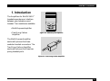
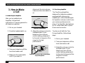
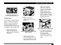
Multi-Purpose Amplifier
HS100A
Two-Prong Carbon
Amplifier
HS101A
FCC INFORMATION
FEDERAL COMMUNICATIONS COMMISSION
AND
INDUSTRY CANADA
RADIO FREQUENCY INTERFERENCE STATEMENTS
This equipment generates, uses, and can radiate radio frequency energy and if not installed and used
properly, that is, in strict accordance with the manufacturer’s instructions, may cause interference to radio
communication. It has been tested and found to comply with the limits for a Class A computing device in
accordance with the specifications in Subpart J of Part 15 of FCC rules, which are designed to provide
reasonable protection against such interference when the equipment is operated in a commercial
environment. Operation of this equipment in a residential area is likely to cause interference, in which case
the user at his own expense will be required to take whatever measures may be necessary to correct the
interference.
Changes or modifications not expressly approved by the party responsible for compliance could void the
user’s authority to operate the equipment.
This digital apparatus does not exceed the Class A limits for radio noise emission from digital apparatus set out in the
Radio Interference Regulation of Industry Canada.
Le présent appareil numérique n’émet pas de bruits radioélectriques dépassant les limites applicables aux appareils
numériques de classe A prescrites dans le Règlement sur le brouillage radioélectrique publié par Industrie Canada.
1
MULTI-PURPOSE AMPLIFIER AND TWO-PRONG CARBON AMPLIFIER
FCC REQUIREMENTS FOR TELEPHONE-LINE EQUIPMENT
1. The Federal Communications Commission (FCC) has established rules which permit this device to be
directly connected to the telephone network with standardized jacks. This equipment should not be
used on party lines or coin lines.
2. If this device is malfunctioning, it may also be causing harm to the telephone network; this device
should be disconnected until the source of the problem can be determined and until the repair has
been made. If this is not done, the telephone company may temporarily disconnect service.
3. If you have problems with your telephone equipment after installing this device, disconnect this device
from the line to see if it is causing the problem. If it is, contact your supplier or an authorized agent.
4. The telephone company may make changes in its technical operations and procedures. If any such
changes affect the compatibility or use of this device, the telephone company is required to give
adequate notice of the changes.
5. If the telephone company requests information on what equipment is connected to their lines, inform
them of:
a. The telephone number that this unit is connected to.
b. The ringer equivalence number.
c. The USOC jack required: RJ-11C.
d. The FCC registration number.
2
CDC STATEMENT
Items (b) and (d) can be found on the unit’s FCC label. The ringer equivalence number (REN) is used
to determine how many devices can be connected to your telephone line. In most areas, the sum of the
RENs of all devices on any one line should not exceed five (5.0). If too many devices are attached, they
may not ring properly.
6. In the event of an equipment malfunction, all repairs should be performed by your supplier or an
authorized agent. It is the responsibility of users requiring service to report the need for service to the
supplier or to an authorized agent.
CERTIFICATION NOTICE FOR EQUIPMENT USED IN CANADA
The Canadian Department of Communications label identifies certified equipment. This certification means
that the equipment meets certain telecommunications-network protective, operation, and safety
requirements. The Department does not guarantee the equipment will operate to the user’s satisfaction.
Before installing this equipment, users should ensure that it is permissible to be connected to the facilities of
the local telecommunications company. The equipment must also be installed using an acceptable method of
connection. In some cases, the company’s inside wiring associated with a single-line individual service may be
extended by means of a certified connector assembly (extension cord). The customer should be aware that
compliance with the above conditions may not prevent degradation of service in some situations.
Repairs to certified equipment should be made by an authorized Canadian maintenance facility—in this case,
your supplier. Any repairs or alterations made by the user to this equipment, or equipment malfunctions,
may give the telecommunications company cause to request the user to disconnect the equipment.
Users should ensure for their own protection that the electrical ground connections of the power utility,
telephone lines, and internal metallic water pipe system, if present, are connected together. This precaution
may be particularly important in rural areas.
3
MULTI-PURPOSE AMPLIFIER AND TWO-PRONG CARBON AMPLIFIER
CAUTION:
Users should not attempt to make such connections themselves, but should contact the appropriate electric inspection authority,
or electrician, as appropriate.
The LOAD NUMBER (LN) assigned to each terminal device denotes the percentage of the total load to be
connected to a telephone loop which is used by the device, to prevent overloading. The termination on a
loop may consist of any combination of devices, subject only to the requirement that the total of the load
numbers of all the devices does not exceed 100.
NORMAS OFICIALES MEXICANAS (NOM) ELECTRICAL SAFETY STATEMENT
INSTRUCCIONES DE SEGURIDAD
1. Todas las instrucciones de seguridad y operación deberán ser leídas antes de que el aparato eléctrico
sea operado.
2. Las instrucciones de seguridad y operación deberán ser guardadas para referencia futura.
3. Todas las advertencias en el aparato eléctrico y en sus instrucciones de operación deben ser respetadas.
4. Todas las instrucciones de operación y uso deben ser seguidas.
5. El aparato eléctrico no deberá ser usado cerca del agua—por ejemplo, cerca de la tina de baño, lavabo,
sótano mojado o cerca de una alberca, etc..
6. El aparato eléctrico debe ser usado únicamente con carritos o pedestales que sean recomendados por
el fabricante.
4
NOM STATEMENT
7. El aparato eléctrico debe ser montado a la pared o al techo sólo como sea recomendado por el
fabricante.
8. Servicio—El usuario no debe intentar dar servicio al equipo eléctrico más allá a lo descrito en las
instrucciones de operación. Todo otro servicio deberá ser referido a personal de servicio calificado.
9. El aparato eléctrico debe ser situado de tal manera que su posición no interfiera su uso. La colocación
del aparato eléctrico sobre una cama, sofá, alfombra o superficie similar puede bloquea la ventilación,
no se debe colocar en libreros o gabinetes que impidan el flujo de aire por los orificios de ventilación.
10. El equipo eléctrico deber ser situado fuera del alcance de fuentes de calor como radiadores, registros
de calor, estufas u otros aparatos (incluyendo amplificadores) que producen calor.
11. El aparato eléctrico deberá ser connectado a una fuente de poder sólo del tipo descrito en el
instructivo de operación, o como se indique en el aparato.
12. Precaución debe ser tomada de tal manera que la tierra fisica y la polarización del equipo no sea
eliminada.
13. Los cables de la fuente de poder deben ser guiados de tal manera que no sean pisados ni pellizcados
por objetos colocados sobre o contra ellos, poniendo particular atención a los contactos y receptáculos
donde salen del aparato.
14. El equipo eléctrico debe ser limpiado únicamente de acuerdo a las recomendaciones del fabricante.
15. En caso de existir, una antena externa deberá ser localizada lejos de las lineas de energia.
16. El cable de corriente deberá ser desconectado del cuando el equipo no sea usado por un largo periodo
de tiempo.
5
MULTI-PURPOSE AMPLIFIER AND TWO-PRONG CARBON AMPLIFIER
17. Cuidado debe ser tomado de tal manera que objectos liquidos no sean derramados sobre la cubierta u
orificios de ventilación.
18. Servicio por personal calificado deberá ser provisto cuando:
A: El cable de poder o el contacto ha sido dañado; u
B: Objectos han caído o líquido ha sido derramado dentro del aparato; o
C: El aparato ha sido expuesto a la lluvia; o
D: El aparato parece no operar normalmente o muestra un cambio en su desempeño; o
E: El aparato ha sido tirado o su cubierta ha sido dañada.
6
TRADEMARKS USED IN THIS MANUAL
TRADEMARKS USED IN THIS MANUAL
AT&T® and Merlin® are registered trademarks of AT&T.
Black Box® is a registered trademark of Black Box Corporation.
Northern Telecom® is a registered trademark of Nortel Networks.
Panasonic® is a registered trademark of Matsushita Electric Industrial Co., Ltd.
Toshiba® is a registered trademark of Toshiba Corporation.
Any other trademarks mentioned in this manual are acknowledged to be the property of the trademark
owners.
7
MULTI-PURPOSE AMPLIFIER AND TWO-PRONG CARBON AMPLIFIER
Contents
1. Introduction . . . . . . . . . . . . . . . . . . . . . . . . . . . . . . . . . . . . . . . . . . . . . . . . . . . . . . . . . . . . . . . . . . . 9
2. Installation . . . . . . . . . . . . . . . . . . . . . . . . . . . . . . . . . . . . . . . . . . . . . . . . . . . . . . . . . . . . . . . . . . . . 10
2.1 Multi-Purpose Amplifier . . . . . . . . . . . . . . . . . . . . . . . . . . . . . . . . . . . . . . . . . . . . . . . . . . . . . . 10
2.2 Two-Prong Amplifier. . . . . . . . . . . . . . . . . . . . . . . . . . . . . . . . . . . . . . . . . . . . . . . . . . . . . . . . . 11
3. How to Make a Call . . . . . . . . . . . . . . . . . . . . . . . . . . . . . . . . . . . . . . . . . . . . . . . . . . . . . . . . . . . . . 12
3.1 Multi-Purpose Amplifier . . . . . . . . . . . . . . . . . . . . . . . . . . . . . . . . . . . . . . . . . . . . . . . . . . . . . . 12
3.2 Two-Prong Amplifier. . . . . . . . . . . . . . . . . . . . . . . . . . . . . . . . . . . . . . . . . . . . . . . . . . . . . . . . . 12
4. Telephone Compatibility and Setup . . . . . . . . . . . . . . . . . . . . . . . . . . . . . . . . . . . . . . . . . . . . . . . 14
4.1 Setup Process 1 . . . . . . . . . . . . . . . . . . . . . . . . . . . . . . . . . . . . . . . . . . . . . . . . . . . . . . . . . . . . . 16
4.2 Setup Process 2 . . . . . . . . . . . . . . . . . . . . . . . . . . . . . . . . . . . . . . . . . . . . . . . . . . . . . . . . . . . . . 17
Setup Process 2a. . . . . . . . . . . . . . . . . . . . . . . . . . . . . . . . . . . . . . . . . . . . . . . . . . . . . . . . . . . . . . 18
5. Optional Accessories . . . . . . . . . . . . . . . . . . . . . . . . . . . . . . . . . . . . . . . . . . . . . . . . . . . . . . . . . . . . 19
5.1 On-line Indicator. . . . . . . . . . . . . . . . . . . . . . . . . . . . . . . . . . . . . . . . . . . . . . . . . . . . . . . . . . . . 19
5.2 AC Power Adapter . . . . . . . . . . . . . . . . . . . . . . . . . . . . . . . . . . . . . . . . . . . . . . . . . . . . . . . . . . . 19
6. Troubleshooting . . . . . . . . . . . . . . . . . . . . . . . . . . . . . . . . . . . . . . . . . . . . . . . . . . . . . . . . . . . . . . . 20
6.1 Calling Black Box . . . . . . . . . . . . . . . . . . . . . . . . . . . . . . . . . . . . . . . . . . . . . . . . . . . . . . . . . . . 20
6.2 Shipping and Packaging . . . . . . . . . . . . . . . . . . . . . . . . . . . . . . . . . . . . . . . . . . . . . . . . . . . . . . 20
8
CHAPTER 1: Introduction
1. Introduction
The Amplifiers for BLACK BOX®
headsets operate as an interface
between your telephone and
headset. Two models are available:
headset
on
• Multi-Purpose Amplifier
• Two-Prong Carbon
Amplifier
mute
off
on
low
off
high
volume
Figure 1-1. Multi-Purpose Amplifier.
The Multi-Purpose Amplifier
works with phones that have
modular handset connectors. The
Two-Prong Carbon Amplifier
works with phones that have twoprong headset ports.
Figure 1-2. Two-Prong Carbon Amplifier.
9
MULTI-PURPOSE AMPLIFIER AND TWO-PRONG CARBON AMPLIFIER
2. Installation
2.1 Multi-Purpose Amplifier
Connect all the cords for the
telephone and headset as shown
in Figure 2-1.
HOLD
1
1. Handset cord
2
4
7
*
2. Headset cord
3
<<<
3
5
8
0
6
9
#
>>>
3. Short telephone cord
5
4. Quick Disconnect
5. Headset stand
4
1
NOTE
The Multi-Purpose Amplifier
works with phones that have
modular handset connectors.
The Two-Prong Carbon
Amplifier works with phones
that have two-prong headset
ports.
headse
t
mute
on
off
on
low
volume
off
high
2
Figure 2-1. Installing the Multi-Purpose Amplifier.
10
CHAPTER 2: Installation
2.2 Two-Prong Amplifier
Connect the Two-Prong Amplifier
as shown in Figure 2-2.
4
1. Two-Prong Amplifier
2. Headset cord
3. Quick Disconnect
1
4. Telephone
NOTE
The Multi-Purpose Amplifier
works with phones that have
modular handset connectors.
The Two-Prong Carbon
Amplifier works with phones
that have two-prong headset
ports.
3
2
Figure 2-2. Installing the Two-Prong Amplifier.
11
MULTI-PURPOSE AMPLIFIER AND TWO-PRONG CARBON AMPLIFIER
3. How to Make
a Call
disconnect the microphone,
make sure the mute switch is
on.
3.1 Multi-Purpose Amplifier
After you’ve installed your
Amplifier, follow these
instructions. (They are general for
all telephone systems.)
1. Put on your headset.
2. Press the headset switch on.
headset
on
mute
on
off
Figure 3-2. Mute Switch.
5. Adjust the volume control to
a suitable level. If your
telephone has a volume
control setting, please set it
to the mid- to low-end of the
range for the best
performance.
off
Figure 3-1. Headset Switch.
low
3. Take your telephone off the
hook and make a call.
4. Make sure the mute switch
is off. If you want to
12
high
volume
Figure 3-3. Volume Control on the MultiPurpose Amplifier.
3.2 Two-Prong Amplifier
The Two-Prong Amplifier,
designed for telephone systems
equipped with a two-prong
headset port, offers standard gain.
Its 3-position volume control locks
your volume preference into
place. The Amplifier also features
an 18" coiled cable with a Quick
Disconnect connector.
To place a call with the TwoProng Amplifier, follow these
steps.
1. Put on your headset.
2. Take your telephone off the
hook and make a call.
3. Adjust the volume control to
a suitable level. If your
telephone has a volume
control setting, please set it
to the mid- to low-end of the
range for the best
performance.
CHAPTER 3: How to Make a Call
Volume Control
Figure 3-4. Volume Control on the TwoProng Amplifier.
NOTE
If you’re using the adapter in
the battery mode, low batteries
are indicated by a beeping
noise in the headset.
13
MULTI-PURPOSE AMPLIFIER AND TWO-PRONG CARBON AMPLIFIER
4. Telephone
Compatibility and
Setup
process 1. If your telephone is not
listed in Table 4-1, follow setup
process 2.
Refer to Table 4-1 for the correct
telephone switch setting for your
telephone and follow setup
Table 4-1. Telephone Compatibility
Telephone Manufacturer
Telephone System
Station Telephone Model
Telephone Type Switch
Transmit Control
Require Batteries?
AT&T®
System 75/85,
G1, G2, G3
7100, 7300, and
7400 Series
A
*1-10
NO
AT&T
Merlin®
BTN, BIS, and
7000 Series
AT&T
5ESS ISDN
6500 and 7500 Series
AT&T
1A2
2500, 2564, and
2565 Series
C
1
NO
Executone
Encore
All Sets
ITT/Alcatel
501, 601
2500 and 2800 Series
Panasonic®
DBS 40, 72, 96
VB-4300 Series
Toshiba®
Strata SE and DK
EKT 2101-3102,
EKT 6010-6025
in Headset Port
C
10
NO
Rolm
ETS Series
*Transmit settings vary. Set to a satisfactory level for your telephone while making a call.
14
CHAPTER 4: Telephone Compatibility and Setup
Table 4-1 (continued). Telephone Compatibility
Telephone Manufacturer
Telephone System
Station Telephone Model
AT&T
Merlin Legend
MLX Series
AT&T
Consumer Products
Traditional 100 and
1000 Series
AT&T
Consumer Products
FeaturePhone 400
1300 and 1600 Series
Comdial
Executech
3500 and 6000 Series
Mitel
SX 100, 200, and 2000
Superset 3, 4, and 7
NEC
Electra
DTerm 4 and 5
Northern Telecom®
Unity
All Sets
Northern Telecom
Meridian
M2000 Series
Northern Telecom
DMS 100
M5000 Series
Northern Telecom
Meridian Norstar
M7000 Series
Panasonic
Key System
KX-T Series
Rolm
CBX and ACD Systems
Rolmphone 120,
240, and 400
Telephone Type Switch
Transmit Control
Require Batteries?
E
*1-10
YES
*Transmit settings vary. Set to a satisfactory level for your telephone while making a call.
15
MULTI-PURPOSE AMPLIFIER AND TWO-PRONG CARBON AMPLIFIER
4. Make a call and adjust the
transmit control according
to the level indicated in
Table 4-1 or to a satisfactory
level. See Figure 4-4.
4.1 Setup Process 1
E
te
mu
AC
3. If batteries are required
according to Table 4-1,
insert two AA batteries as
indicated on the bottom of
the battery compartment.
See Figure 4-3.
headse
t
on
mute
off
on
volu
me
off
high
Figure 4-1. Removing the Lid.
2. Adjust the telephone type
switch according to
Table 4-1.
l
+
+
te
mu
l
se
ead
t
on
h
off
on
Figure 4-3. Inserting the Batteries.
16
E
Figure 4-2. Adjusting the Telephone Type
Switch.
2
1. Remove the lid for the
battery compartment by
sliding it to the left and then
lifting it off. See Figure 4-1.
AC
2
If your phone system appears in
Table 4-1, follow these steps to set
up your amplifier. You will not be
able to achieve compatibility
without first following all of the
setup instructions.
t
dse
hea
Figure 4-4. Adjusting the Transmit Control.
5. To replace the battery lid,
align it at the right-hand
side of the battery
compartment and press
down. Then slide it to the
right. See Figure 4-5.
CHAPTER 4: Telephone Compatibility and Setup
head
set
headse
t
set
mute
on
off
low
off
on
Figure 4-5. Replacing the Battery Lid.
4.2 Setup Process 2
If your telephone system does not
appear in Table 4-1, follow this
process. You will not be able to
achieve compatibility without
completing all the points included
in Chapter 3, How to Make a Call.
on
mute
off
on
volu
me
off
high
Figure 4-6. Removing the Lid.
2. Make sure that the
telephone type switch is in
position C.
AC
AC
t
dse
hea
E
te
2
1. Remove the lid for the
battery compartment by
sliding it to the left and then
lifting it off.
E
2
head
on
low
page. If you achieve a
connection, adjust the
transmit control to either
position 1 or 10. (The
middle settings of the
transmit wheel have little
effect in telephone type C
setting. Setting 1 or 10 will
give the best results.)
mu
Figure 4-7. Adjusting the Telephone Type
Switch to Position C.
3. Take the phone off the
hook and make a call. If you
do not get a dial tone, go to
setup process 2a on the next
Figure 4-8. Adjusting the Transmit Control.
4. To replace the battery lid,
align it at the right hand
side of the battery
compartment and press
down. Then slide it to the
right.
17
MULTI-PURPOSE AMPLIFIER AND TWO-PRONG CARBON AMPLIFIER
head
head
set
l
set
off
low
off
on
Figure 4-9. Replacing the Battery Lid.
SETUP PROCESS 2A
1. Adjust the telephone type
switch to position E.
AC
+
mute
on
on
low
+
te
mu
l
set
ead
on
h
off
n
Figure 4-10. Inserting the Batteries.
3. Make a call and adjust the
transmit control to a
satisfactory level. If you still
do not hear a dial tone,
recheck connections and try
the setup again.
E
te
mu
2
Figure 4-10. Adjusting the Telephone Type
Switch to Position E.
AC
E
2
2. Insert the two AA batteries
as indicated on the bottom
of the battery compartment.
t
dse
hea
Figure 4-11. Adjusting the Transmit
Control.
18
4. To replace the battery lid,
align it at the right hand
side of the battery
compartment and press
down. Then slide it to the
right.
head
head
set
set
mute
on
on
low
off
low
off
on
Figure 4-12. Replacing the Battery Lid.
CHAPTER 5: Optional Accessories
5. Optional
Accessories
5.1 On-line Indicator
The on-line indicator lights up
when the headset is in use to
indicate to co-workers that you are
on the telephone. You can adjust
it so the light can be seen from
the direction you prefer.
5.2 AC Power Adapter
Remove the batteries when using
an AC power adapter. The AC
adapter port is indicated by the
arrow in Figure 5-2.
Figure 5-2. AC Power Adapter.
Figure 5-1. On-line Indicator.
19
MULTI-PURPOSE AMPLIFIER AND TWO-PRONG CARBON AMPLIFIER
6. Troubleshooting
6.1 Calling Black Box
If you determine that your
Amplifier is malfunctioning, do
not attempt to alter or repair the
unit. It contains no userserviceable parts. Contact Black
Box at 724-746-5500.
Before you do, make a record of
the history of the problem. We
will be able to provide more
efficient and accurate assistance if
you have a complete description,
including:
• the nature and duration of
the problem.
• when the problem occurs.
• the components involved in
the problem.
20
• any particular application
that, when used, appears to
create the problem or make
it worse.
6.2 Shipping and Packaging
If you need to transport or ship
your Amplifier:
• Package it carefully. We
recommend that you use
the original container.
• If you are shipping the
Amplifier for repair, make
sure you include everything
that came in the original
package. Before you ship,
contact Black Box to get a
Return Materials
Authorization (RMA)
number.
CUSTOMER SUPPORT INFORMATION
Order toll-free in the U.S.: Call 877-877-BBOX (outside U.S. call 724-746-5500)
FREE technical support 24 hours a day, 7 days a week: Call 724-746-5500 or fax 724-746-0746
Mailing address: Black Box Corporation, 1000 Park Drive, Lawrence, PA 15055-1018
Web site: www.blackbox.com • E-mail: [email protected]
54-0156A
June 2000
Printed in USA
© Copyright 2000. Black Box Corporation. All rights reserved.


![mm [mm [1 um um [11115151116 |])|]1]](http://vs1.manualzilla.com/store/data/005839409_1-1dd2adaaab9a040f039445848c9c3135-150x150.png)