1
THESE INSTRUCTIONS ARE TO BE USED ONLY FOR:
MODEL PL845
REV: 05/13
MANUALS FOR OTHER MODELS CAN BE FOUND AT WWW.SOURCEONEOPE.COM
OUTDOOR POWER EQUIPMENT
YouTube channel
SERIAL NUMBER:
__________________________
DATE PURCHASED:
__________________________
INSTRUCTIONS AND PARTS MANUAL
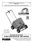
PLUGR PL845 PRO VS 30" TURF AERATOR
PLUGR is a registered trademark of SourceOne Inc., a subsidiary of IMSCORP, Lincoln, NE.
1030 SW 6th Street, Lincoln, NE 68522 • (888) 418-9065 • Fax (402) 474-6605
Website: www.SourceOneOPE.com • Email: [email protected]
THESE INSTRUCTIONS ARE TO BE USED ONLY FOR:
MODEL PL845
MANUALS FOR OTHER MODELS CAN BE FOUND AT WWW.SOURCEONEOPE.COM
PLUGR PL845 PRO VS 30" TURF AERATOR MANUAL
To stop PLUGR: Release the bottom lever. It will automatically spring
down to disengage belt idler. Pull the center lever back to lock. SHUT
Handle: Remove cover from machine; remove two bolts from
OFF ENGINE if not continuing.
bottom of handle. Slide the handle into square receptacles in frame
To remove access cover: Remove cover release rubber latches.
with retractor lever facing up and clutch engagement bail facing
Reverse procedure to replace cover.
down. Insert bolts through handle mount and holes in handle,
making sure bolts are inserted from the bottom up. The hex heads To operate in cold temperatures: Engage tines in "up" position for
on these two bolts needs to fit into the hex hole on the bottom of the at least two minutes prior to actual aeration to warm cam grease.
handle mounts. Tighten nylon nuts.
Retractor Cable: Solid wire cable with identical ends attaches to
black retractor plate with 1/4” x 1 1/2” bolt and lock nut. This is
Journal bearings: Grease journal bearing on the zerks provided
installed at the factory. The other end is placed on the center
every 10 hours of operation. We recommend Almagard® #3752
handle lever. Install cable and place the clevis pin and cotter pin key Grease from Lubrication Engineers®, Inc. Check for wear
back in position.
periodically.
Clutch Cable: Insert clutch cable control knob into clutch bail lever Shaft bearings: Grease both crank shaft ball bearings on the
pivot then slide cable retainer into cable mount bracket and tighten
zerks provided every 100 hours of operation.
top jamb nut down on bracket sandwiching it between both nuts
Wheel bearings: Grease wheel ball bearings on the zerks
and tighten. Preliminary adjustment should be within tolerance from provided every 100 hours of operation..
factory. If adjustments are needed for belt tension, loosen lock nut
Engine oil/filter: See engine manufacturer’s instructions. Change
on control knob and turn knob accordingly. One or two rotations
oil and filter at least once a season per engine manual.
should be sufficient.
V-Belt: Adjust V-belt tightness with adjustment holes in pivoting
Engine: Engine and gear case are factory filled with high quality
detergent SAE 30 oil, (SE, SF, or SG). Check level prior to operation. clutch bracket. It should only be necessary to move to the next
Please refer to the engine manual or call the engine manufacturer at hole. Do not over tighten V-belt. This puts a load on the engine
gear box bearings. The belt is tight enough when it does not slip
the phone number listed in the engine instructions if there are any
during the operating cycle.
questions regarding the engine. NOTE: GASOLINE CAN BE
Tines (threaded type): These are adjustable by only the thickness
HAZARDOUS. HANDLE GASOLINE CAREFULLY AT ALL TIMES! USE
of the jam nut approx. 1/4" and the openings should face the rear of
LEAD FREE GASOLINE WITHOUT OIL MIXED IN.
the PLUGR. They are replaceable by loosening the jam lock nut and
unscrewing the tine. All threads are right hand. Install the tine with
the jam lock nut on the tine and use maximum threads inserted into
the tine casting. Tighten jam lock nut against the tine casting.
CAUTION! KEEP FINGERS FROM BEING PINCHED UNDER THE
Decals: All safety decals are available for replacement at no cost.
MOVING HAND LEVERS DURING ENGAGEMENT.
Do not operate without all warning labels clearly readable.
Speed adjustment knob: There is an adjustable retractor lock
found on the back panel of the aerator. Hold the ball knob on the
end of the lever, pull the spring-loaded adjustable retractor lock, to
move the lever between the 3 different settings, H(igh), M(edium),
Machine Width
30"
and L(ow).
Aeration Width Per Pass
30"
Bottom lever: This lever engages the drive belt idler. Pull it up to
engage. This lever must be held up for machine operation. When
Hole Centers
2.6" x 7.5"
released, forward motion will stop. If the lever fails to spring down
Hole Depth (Up to)
2.75"
when released, contact the manufacturer immediately for
Plug Diameter
5/8"
adjustment instructions as this is a safety feature.
Approx.
Sq.
Ft.
Per
Hour
(Up
to)
42,500
Center lever: This lever swings the plugr mechanism forward into
Shipping Weight
334 lbs.
the operating position. Release handle and allow lever to move
forward. It will automatically pull itself into operating position.
Actual Machine Weight
284 lbs.
To aerate: Release the center lever and allow tines to move
Tire
10"
forward. Pull the bottom lever up and hold. Do not push machine
Belt Drive Clutch
Double V-type
while operating. The holes will be deeper if you allow the PLUGR to
Nylatron Cam Bearings
pull itself forward as the tines penetrate the soil.
ASSEMBLY INSTRUCTIONS
MAINTENANCE INSTRUCTIONS
OPERATING INSTRUCTIONS
SPECIFICATIONS
MANUAL DEL AIREADOR PLUGR DE CÉSPED PRO VS DE 30"
INSTRUCCIONES DE ENSAMBLADO
Mango: Retire la tapa de la máquina; quite los 2 tornillos de la parte
inferior del mango. Deslice el mango en recipientes cuadrados en marco
con la palanca hacia arriba y retractor fianza de accionamiento de
embrague hacia abajo. Inserte los pernos de montaje a través de agujeros
en el mango y el mango, por lo que los tornillos estén insertados desde
abajo hacia arriba. Las cabezas hexagonales en estos dos pernos necesita
encajar en el orificio hexagonal en la parte inferior de los montajes de las
manijas. Apretar las tuercas de nylon.
Cable retractor: El cable sólido de alambre con extremos idénticos ata al
disco negro retractor con el perno de 1/4” x 11/2” y la tuerca. Esto es
instalado de fábrica. El otro extremo es colocado en el centro de la
palanca. Instale el cable y coloque los alfileres de clevis y chaveta de
nuevo en posición.
Cable del embrague: Inserte el cable del embrague perilla de control del
embrague en libertad bajo fianza luego de retención eje de la palanca
deslizante cable al cable de soporte de montaje y apriete la tuerca de la
jamba de arriba hacia abajo en el soporte intercalando entre lo dos
tuercas y apriete. Ajuste preliminar debe estar dentro de la tolerancia de
fábrica. Si los ajustes son necesarios para la tensión de la correa, afloje la
tuerca de la perilla de control y gire la perilla en consecuencia. Una o dos
rotaciones debería ser suficiente.
Motor: El motor y engranaje vienen rellenos de fábrica con aceite
detergente SAE 30 de alta calidad, (SE, SF o SG). Checar el nivel antes de
la operación. Por favor consulte el manual del motor o llame al fabricante
del motor a el número de teléfono listado en las instrucciones del motor si
tiene alguna pregunta acerca del motor. NOTA: LA GASOLINA PUEDE SER
PELIGROSA. MANEJE LA GASOLINA CUIDADOSAMENTE EN TODO
MOMENTO. USE GASOLINA LIBRE DE PLOMO SIN ACEITE MEZCLADO.
INSTRUCCIONES DE OPERACIÓN
PRECAUCION! IMPIDA QUE LOS DEDOS SEAN PELLIZCADOS POR LAS
PALANCAS MOVILES DURANTE EL ENGRANE.
Velocidad perilla de ajuste: Hay una cerradura retractor ajustable
encuentra en el panel posterior del aireador. Mantenga la perilla bola en el
extremo de la palanca, tire de la cerradura de resorte retractor ajustable,
para mover la palanca entre los 3 diferentes ajustes alto, medio y bajo.
Palanca a mano derecha: Esta palanca hace que la banda quede
inactiva. Jalarla para atrás para activarla. Esta palanca debe de
mantenerse hacia abajo para la operación de la máquina. Cuando es
liberada, el movimiento hacia adelante se parará. Si la palanca falla
avanzando hacia adelante, póngase en contacto con el fabricante
inmediatamente para instrucciones de ajuste ya que este es un
equipamiento de seguridad.
Palanca a mano izquierda: Esta palanca balancea el mecanismo plugr
avanzado hacia la posición de operación. Con la palanca a mano derecha
engranada, libere el seguro del transportador en el mango y permita que
la palanca avance. Esto lo pondrá automáticamente en la posición de
operación.
Para ventilar: Jale la palanca a mano derecha para atrás y sosténgala.
Libere la palanca a mano izquierda y permita que avance hacia adelante.
NO empuje la máquina cuando esté funcionando. Los agujeros serán más
profundos si usted permite que el PLUGR avance hacia adelante cuando
los dientes penetran la tierra.
Para parar PLUGR: Libere la palanca a mano derecha. Esta saltará
automáticamente para soltar el inactivador de la banda. Jale la palanca a
mano izquierda hacia atrás y engrane el seguro transportador. APAGUE EL
MOTOR sino continua.
Para abrir la tapa de acceso: Para abrir la tapa de acceso, quite el tornillo
del centro y libere los pestillos de goma. Procedimiento inverso para
recolocar la tapa.
Para operar en bajas temperaturas: Engrane los dientes en la posición
hacia “arriba” por lo menos dos minutos antes de empezar la aireación para
calentar la grasa de las levas.
INSTRUCCIONES DE MANTENIMIENTO
Porte de diario: Engrase el cojinete de los zerks proporcionados cada 10
horas de operación. Recomendamos Almagard R #3752 Grasa de
Lubricación Engineer R, Inc. Revisar periodicamente el desgaste.
Portes de Eje: Engrase ambos portes de eje de manivela proporcionados
en los zerks cada 100 horas de operación.
Portes de Rueda: Engrase los portes de rueda proporcionados en los
zerks cada 100 horas de operación.
Aceite para Motor/Filtro: Ver las instrucciones del fabricante del motor.
Cambio de aceite y filtro al menos una vez cada temporada de acuerdo al
manual del motor.
Correa de Distribución: Ajuste la correa de distribución con los agujeros
ajustables pivoteando el soporte del embrague. Solo es necesario moverlo
al siguiente agujero. No sobre ajuste la correa de distribución. Este pone
una carga sobre los portes de caja de la marcha del motor. La banda está
bastante apretada para que no se resbale durante el ciclo de operación.
Dientes (tipo enhebrado): Estos son ajustables por el grosor de la tuerca
aproximadamente 1/4” y las aperturas deben afrontar el reverso del
PLUGR. Ellos son reemplazables soltando el seguro de la tuerca y
desatornillando el diente. Todos los hilos giran a mano derecha. Instale el
diente con el seguro de la tuerca en el diente y use los hilos máximos
insertados en el bastidor del plugger. Ajustar el seguro de la tuerca al
bastidor del plugger.
Etiquetas: Todas las etiquetas de seguridad están disponibles para su
reemplazo gratis. No operarlo sin todas las etiquetas de advertencia
claramente legibles.
ESPECIFICACIONES
Anchura de la Máquina
30"
Anchura de Aireación por pase
30"
Agujero central
2.6" x 7.5"
Profundidad del Agujero (hasta)
2.75"
Diámetro del Enchufe
5/8"
Aprox. Pies Cuadrados
42,500
por hora (hasta)
Peso del Embarque
334 libras
Peso real de la Máquina
284 libras
Rueda del Cojinete
10"
Correa de Embrague
doble tipo-V
Portes de Leva de Nylatron
SAFETY INSTRUCTIONS Instrucciones de Seguridad
Turf aerators are designed exclusively for the purpose of the improvement of turf grass by removing "plugs" of existing
turf to allow the flow of nutrients, water and oxygen to the roots. Any other use is unadvisable and can cause serious
injury or death. Los aireadores de césped son diseñados exclusivamente con el objetivo de mejorar el césped removiendo
los tapones existentes de hierba para permitir el flujo de sustancias nutritivas, agua y oxígeno a las raíces. Cualquier otro uso
no es aconsejable y puede causar serias heridas o la muerte.
DO HACER:
•
•
•
•
•
•
•
•
•
•
Always follow operating instructions. Siempre seguir las instrucciones de operación.
Operate only with the guard/cover in place. Operar sólo con la cubierta/tapa en su lugar.
Wear protective equipment including hearing protection, eye shields and proper footwear. Usar equipo de protección
incluyendo protección auditiva, lentes protectores y artículos de calzado apropiados.
Read and heed all warning labels affixed to the machine. Leer y prestar atención a las etiquetas de advertencia
adjuntas a la máquina.
Remove spark plug wire when machine is not being used to prevent operation without instruction. Quitar el alambre
de bujía cuando la máquina no esté en uso para prevenir la operación sin instrucción.
Clear area to be aerated of all loose objects and all children. Limpiar el área a ser ventilada de objetos sueltos y todos
los niños.
Flag sprinkler heads and other hidden obstacles and holes. Marcar las cabezas de los aspersores y otros obstáculos
escondidos y agujeros.
Practice operation in an open area prior to operation in tight areas. Practicar la operación en un área abierta antes de
operar en áreas estrechas.
Keep hands and feet away from operating parts. Mantener manos y pies fuera del alcance de las partes operadoras.
Use hearing protection. Tested noise levels range from 86.4dB(A)-89.5dB(A). Usar protección auditiva. Niveles de
ruido probados oscilan entre los 86.4 dB (A) hasta los 89.5 dB (A).
DO NOT NO HACER:
•
•
•
•
•
•
•
•
•
•
•
•
Operate on severe slopes (exceeding 15˚). Operar sobre cuestas severas (excediendo 15º).
Allow children to operate or be within 50' of operation. Permitir a niños operarlo o que estén dentro de 50’ de la
operación.
Operate without guard/cover attached. Operar sin la tapa / cubierta puesta.
Operate when footing is unsure. Operar cuando el equilibrio es inseguro.
Leave machine unattended while running. Dejar la máquina desatendida mientras funciona.
Operate when dark or hard to see clearly. Operar cuando está oscuro o difícil de ver claramente.
Override the safety shutoff switch. Anular el interruptor de apagado de seguridad.
Lift guard/cover without positioning body to avoid lift injury. Levantar la tapa/cubierta sin posicionar el cuerpo para
evitar un herida de levantamiento.
Allow feet to be placed under the rear of machine. Permitir que los pies sean colocados bajo el reverso de la máquina.
Operate without instructions. Operar sin instrucciones.
Allow others to operate without access to instructions. Permitir a otros su operación sin acceso a las instrucciones.
Operate without warning labels clearly readable. Operar sin las etiquetas de advertencia claramente legibles.
NEVER ALLOW CHILDREN TO OPERATE POWER EQUIPMENT
NUNCA PERMITIR A NIÑOS OPERAR EL EQUIPO DE PODER
MACHINE LABELS Etiquetas de la Máquina
DO NOT OPERATE MACHINERY WITHOUT SAFETY LABELS. FREE REPLACEMENT LABELS
ARE AVAILABLE UPON REQUEST BY CONTACTING SOURCEONE CUSTOMER SERVICE.
Parts Diagram for Model PL845
PLSS - RETRACTOR PLATE
DETAIL VIEW
71
72
43
24
7
70
67
74
30
72
4
68
24
66
4
69
24
55
40
19
71
73
44
65
52
4
54
38
16
42
64
45
23
9
59
7
76
26
3
20
79
77
27
2
32
78
29
25
36
35
75
10
33
17
12
39
21
8
6
41
54
37
PLSS
39
50
22
61
2
4
29
58
8
41
81
80
11
39
12
28
15
14
43
51
46
43
53
57
10
7
47
17
31
39
55
13
62
5
62
60
51
56
34
48
63
17
34
1
18
51
Parts List for Model PL845
ITEM #
PART #
QTY. DESCRIPTION
ITEM #
PART #
QTY. DESCRIPTION
1
PL1003
4
Rubber Latch Kit
51
PL1634
2
2
PL1015
12
Flat Washer, Ø5/16
52
PL1637
1
Cable Adjustment Spool
3
PL1018
2
Engine Pulley, Ø3.5
53
PL1653
4
Wheel, 12" w Ø5/8 Bearing Hub
4
PL1029
7
Nylock Nut, 1/4-20 UNC
54
PL1655
2
Push Pull Cable, 55"
5
PL1031
2
Cotter Pin, Ø1/16 x 3/4"
55
PL1659
2
Cotter Pin, Ø3/32 x 3/4"
6
PL1042
2
Cartridge Bearing, Ø1.0
56
PL1663
1
Extension Spring, Ø1/2 x 3"-5"
7
PL1044
28
Flat Washer, Ø3/8
57
PL1667
4
Hex Bolt, 3/8-16 UNC x 1-1/2"
8
PL1045
4
Nylock Nut, 3/8-16 UNC
58
PL1668
4
Hex Bolt, 5/8-11 UNC x 4-1/2"
9
PL1052
8
Grease Fitting, 1/4-28
59
PL1671
2
Cogged V-Belt, B 35"
10
PL1056
12
Jam Nut, 5/8-11 UNC
60
PL1675
2
Clevis Pin, Ø3/16 x 3/4"
11
PL1057
8
Tine, Ø5/8
61
PL1684
1
Safety Switch Ground Wire
12
PL1072
8
Nylock Nut, 5/16-18 UNC
62
PL1694
2
Bushing, 1/2 ID x 5/8 OD x 1"
13
PL1077
1
Clevis Pin, Ø1/4 x 3/4"
63
PL1711
1
800 Series Frame
14
PL1078
1
Hex Bolt, 1/2-13 UNC x 2-1/2"
64
PL1712
1
800 Series Cover
15
PL1079
2
Idler Pulley, Ø2.75 (LH & RH)
65
PL1713
1
SS Retractor Plate
16
PL1089
1
Retractor Plate Cable
66
PL1714
8
Tine Rocker
PL1716
8
Clevis Pin, Ø3/8 x 2"
Clutch Cam Arm
17
PL1091
5
Flat Washer, Ø1/4
67
18
PL1115
8
Stainless Rivet, Ø1/8 x 1/4
68
PL1717
1
PLSS Central Clevis Bar, Ø3/8
19
PL1116
4
Domed Bumper, Ø1
69
PL1718
4
R.H. Tine Torsion Spring
20
PL1123
1
Key, 3/16" x 1-1/2"
70
PL1719
4
L.H. Tine Torsion Spring
21
PL1126
1
Safety Switch Wire
71
PL1720
16
Tine Roller
22
PL1129
1
Safety Switch
72
PL1721
16
E-Clip, Ø3/8
23
PL1142
16
Hex Bolt, 3/8-16 UNC x 2"
73
PL1722
1
800 Series Handle
24
PL1158
4
Shoulder Bolt, Ø5/16 x 1/4"
74
PL1723
1
800 Series Clutch Lever
25
PL1175
8
Tine Rod
75
PL1747
1
Adjustable Retractor Yoke
26
PL1176
8
Tine Rod Cap
76
PL1748
1
Phenolic Ball Knob
27
PL1177
16
Journal Bearing, Ø2.0
77
PL1750
1
Adjustable Retractor Lock Plug
28
PL1178
4
Fender Washer, Ø5/16
78
PL1751
1
Retractor Adjustment Lever
29
PL1179
18
Lock Nut, 3/8-16 UNC
79
PL1753
1
Spring, Ø.72 x 2.0"- 0.6"
30
PL1201
1
Retractor Handle
80
PL1757
4
Washer, USS Ø5/16 Thru-Hard
31
PL1237
1
Spherical Rod End, 10-32 UNF
81
PL1758
2
Shoulder Bolt, Ø1/2 x 5/8"
32
PL1248
4
Hex Bolt, 5/16-18 UNC x 1-3/4"
33
PL1252
4
Hex Bolt, 1/4-20 UNC x 3/4"
34
PL1267
4
Hex Bolt, 1/4-20 UNC x 1"
35
PL1269
1
Nylock Nut, 1/2-13 UNC
36
PL1272
1
Eyebolt, Ø1/2 x 1/4-20 UNC
37
PL1291
2
Rivet, Ø3/16 x 3/8"
38
PL1328
2
Hex Bolt, 1/4-20 UNC x 1-3/4"
39
PL1329
7
Flat Washer, Ø1/2
40
PL1345
1
Clevis Pin, Ø1/4 x 1-1/8"
41
PL1512
4
Bushing, 1/2 ID x 3/4 OD x 1/2"
42
PL1522
1
8 Tine Crankshaft
43
PL1523
6
Cotter Pin, Ø1/8 x 1"
44
PL1524
4
Rivet, Ø3/16 x 3/4"
45
PL1610
1
GX160 Honda Engine w/ Gearbox
46
PL1625
1
Prehard Roller
47
PL1629
1
Lower Belt Tension Bracket
48
PL1630
1
Upper Belt Tension Bracket
49
PL1632
2
Retractor Plate Arm
50
PL1633
1
Clutch Profile Arm
THESE INSTRUCTIONS ARE TO BE USED
ONLY FOR:
MODEL PL845
MANUALS FOR OTHER MODELS CAN BE
FOUND AT WWW.SOURCEONEOPE.COM
WARRANTY
LIMITED WARRANTY FOR PLUGR TURF AERATOR (engine excluded)
For two full years from date of purchase and first use, SourceOne will replace for the original purchaser free of charge any parts of the machine
(excluding engine, hydrostat, tines and belts) found upon examination by SourceOne or its approved agent to be defective in material or
workmanship or both. This is the exclusive warranty.
All expedited transportation charges on parts submitted for replacement must be borne by purchaser. For warranty service contact the dealer from
whom you purchased machine or the factory in Lincoln, Nebraska which reserves the right to examine the machine and make its own evaluation
at its option. THERE IS NO OTHER EXPRESS WARRANTY. IMPLIED WARRANTIES, INCLUDING THOSE OF MERCHANTABILITY AND FITNESS FOR A
PARTICULAR PURPOSE, ARE LIMITED TO ONE YEAR FROM DATE OF PURCHASE. TO THE EXTENT PERMITTED BY LAW ANY AND ALL IMPLIED
WARRANTIES ARE EXCLUDED. LIABILITY FOR CONSEQUENTIAL DAMAGES UNDER ANY AND ALL WARRANTIES ARE EXCLUDED TO THE EXTENT
EXCLUSION IS PERMITTED BY LAW. Some jurisdictions do not allow limitations on how long an implied warranty lasts, and some jurisdictions do
not allow the exclusion or limitation of incidental or consequential damages, so the above limitation and exclusion may not apply to you. This
warranty gives you specific legal rights and you may also have other rights, which may vary from jurisdiction to jurisdiction.
GARANTIA
GARANTIA LIMITADA PARA AIREADOR DE CESPED PLUGR (motor excluido)
Durante dos años completo a partir de la fecha de la compra y el primer uso, SourceOne sustituirá al comprador original gratuitamente cualquier
parte de la máquina (excluyendo motor, hidrostato, dientes y bandas) de acuerdo a lo encontrado en el examen por SourceOne o su agente
aprobado que esté defectuoso en material o habilidad o ambos. Esta es la garantía exclusiva.
Todos los gastos de envio expedito para reemplazo de partes deben correr por cuenta del comprador. Para servicio de la garantía ponerse en
contacto con el distribuidor con quien usted compró la máquina o la fábrica en Lincoln, Nebraska quien se reserva el derecho de examinar la
máquina y hacer su propia evaluación a su opción. NO HAY NINGUNA OTRA GARANTIA EXPRESS. LAS GARANTIAS IMPLICITAS, INCLUSO AQUELLAS
DE VALOR COMERCIAL Y SALUD PARA UN OBJETIVO PARTICULAR, SON LIMITADAS A UN AÑO A PARTIR DE LA FECHA DE COMPRA. HASTA CIERTO
PUNTO SEGUN LA LEY ALGUNA Y TODAS LAS GARANTIAS IMPLICITAS SON EXCLUIDAS. LA RESPONSABILIDAD DE DAÑOS CONSECUENTES BAJO
ALGUNA Y TODAS LAS GARANTIAS ES EXCLUIDA DE ACUERDO A LA LEY. Algunas jurisdicciones no permiten limitaciones sobre cuanto tiempo una
garantía implícita puede durar, y algunas jurisdicciones no permiten la exclusión o la limitación de daños secundarios o consecuentes, entonces la
susodicha limitación y exclusión puede no aplicarse con usted. Esta garantía le da derechos legales específicos y usted puede tener también otros
derechos, que pueden variar de jurisdicción a jurisdicción.