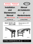
1
IMPORTANT!
IMPORTANTE!
DO NOT DESTROY
NO DESTRUIR
Manual
Installation
de Instalación
and
y
Maintenance
Mantenimiento
Manual
with Safety Information
con Información sobre Seguridad
and Parts List
y Lista de Partes
RECOMMENDED SPARE PARTS HIGHLIGHTED IN GRAY
PARTES DE REPUESTO RECOMENDADAS SE RESALTAN EN GRIS
Model 138-NSP, NSPC
NSPS, & NSPSS
Effective January, 2002
Bulletin # 497
HYTROL CONVEYOR CO., INC.
© COPYRIGHT 2002–HYTROL CONVEYOR CO., INC.
Jonesboro, Arkansas
● Table of Contents
2
● Tabla de Contenido
Warning Signs . . . . . . . . . . . . . . . . . . . .3
Señales de Advertencia . . . . . . . . . . . . . . .3
INTRODUCTION
Receiving and Uncrating . . . . . . . . . . . .4
INTRODUCCION
Recepción y Desembalaje . . . . . . . . . . . . .4
INSTALLATION
Installation Safety Precautions . . . . . . . .5
Support Installation . . . . . . . . . . . . . . . .6
Ceiling Hanger Installation . . . . . . . . . . .7
Conveyor Set-Up . . . . . . . . . . . . . . . . . .8
Racked Sections . . . . . . . . . . . . . . . . .10
Electrical Equipment . . . . . . . . . . . . . .12
INSTALACION
Medidas de Seguridad al Instalar . . . . . . . .5
Instalación de los Soportes . . . . . . . . . . . .6
Instalación de los Soportes de Techo . . . . .7
Disposición del Transportador . . . . . . . . . .8
Secciones Escuadradas . . . . . . . . . . . . .10
Equipo Eléctrico . . . . . . . . . . . . . . . . . . .12
OPERATION
Operation Safety Precautions . . . . . . .14
Conveyor Start-Up . . . . . . . . . . . . . . . .14
OPERACION
Medidas de Seguridad . . . . . . . . . . . . . .14
Arranque del Transportador . . . . . . . . . . .14
MAINTENANCE
Maintenance Safety Precautions . . . . .15
Lubrication . . . . . . . . . . . . . . . . . . . . .15
Drive Chain Alignment and Tension . . .16
Trouble Shooting . . . . . . . . . . . . . . . .17
Maintenance Checklist . . . . . . . . . . . . .18
How To Order Replacement Parts . . . .19
MANTENIMIENTO
Medidas de Seguridad . . . . . . . . . . . . . . .15
Lubricación . . . . . . . . . . . . . . . . . . . . . . .15
Alineación y Tensión de la Cadena . . . . .16
Resolviendo Problemas . . . . . . . . . . . . . .17
Mantenimiento Preventivo . . . . . . . . . . .18
Como Ordenar Partes de Repuesto . . . . .19
REPLACEMENT PARTS
Model 138-NSP Parts Drawings . . . . . .20
Model 138-NSP Parts List . . . . . . . . . .21
Model 138-NSPC 90° Parts Drawings .22
Model 138-NSPC 90° Parts List . . . . . .23
Model 138-NSPC 60° Parts Drawings .24
Model 138-NSPC 60° Parts List . . . . . .25
Model 138-NSPC 45° Parts Drawings .26
Model 138-NSPC 45° Parts List . . . . . .27
Model 138-NSPC 30° Parts Drawings .28
Model 138-NSPC 30° Parts List . . . . . .29
Model 138-NSPS 45° Parts Drawings .30
Model 138-NSPS 45° Parts List . . . . . .31
Model 138-NSPS 30° Parts Drawings .32
Model 138-NSPS 30° Parts List . . . . . .33
Model 138-NSPSS 45° Parts Drawings 34
Model 138-NSPSS 45° Parts List . . . . .35
Model 138-NSPSS 30° Parts Drawings 36
Model 138-NSPSS 30° Parts List . . . . .37
PARTES DE REPUESTO
Modelo 138-NSP Dibujo de Partes . . . . . .20
Modelo 138-NSP Lista de Partes . . . . . . .21
Modelo 138-NSPC 90° Dibujo de Partes .22
Modelo 138-NSPC 90° Lista de Partes . .23
Modelo 138-NSPC 60° Dibujo de Partes .24
Modelo 138-NSPC 60° Lista de Partes . .25
Modelo 138-NSPC 45° Dibujo de Partes .26
Modelo 138-NSPC 45° Lista de Partes . .27
Modelo 138-NSPC 30° Dibujo de Partes .28
Modelo 138-NSPC 30° Lista de Partes . .29
Modelo 138-NSPS 45° Dibujo de Partes .30
Modelo 138-NSPS 45° Lista de Partes . .31
Modelo 138-NSPS 30° Dibujo de Partes .32
Modelo 138-NSPS 30° Lista de Partes . .33
Modelo 138-NSPSS 45° Dibujo de Pts . . .34
Modelo 138-NSPSS 45° Lista de Partes .35
Modelo 138-NSPSS 30° Dibujo de Pts . . .36
Modelo 138-NSPSS 30° Lista de Partes .37
● Warning Signs
In an effort to reduce the possibility of injury to personnel
working around HYTROL conveying equipment, warning
signs are placed at various points on the equipment to alert
them of potential dangers. Please check equipment and
note all warning signs. Make certain your personnel are
alerted to and obey these warnings. Shown below are typical signs that are attached to this equipment.
WARNING!
ADVERTENCIA!
DO NOT START CONVEYOR
UNTIL PERSONNEL ARE CLEAR
NO PONER EN MARCHA EL TRANSPORTADOR
HASTA QUE TODO EL PERSONAL ESTE ALEJADO
PLACED ON ALL POWERED
CONVEYORS NEAR DRIVE
AND/OR CONTROLS.
COLOCADA EN TODOS LOS
TRANSPORTADORES
MOTORIZADOS CERCA AL
MOTOR Y/O LOS CONTROLES
● Señales de Advertencia
En un esfuerzo por reducir la posibilidad de accidentes al personal trabajando junto al equipo de transportación HYTROL,
se colocan señales de advertencia en diferentes puntos del
equipo para alertarlos de riesgos potenciales. Por favor verifique el equipo y asegúrese de ver todas las señales de
advertencia. Asegúrese de que su personal esté alerta y obedezca las señales. Abajo se muestran las señales que se
encuentran en este equipo.
WARNING
ADVERTENCIA!
Servicing moving or
energized equipment
can cause severe injury
El mantenimiento de
partes el ctricas o en
movimiento puede
causar lesiones graves.
LOCK OUT POWER
DESCONECTAR la energ a
antes de remover la guarda.
before removing guard
COLOCADA JUNTO A LA UNIDAD
MOTRIZ, EN AMBOS LADOS.
PLACED NEXT TO DRIVE, BOTH
SIDES.
DANGER
PELIGRO!
Climbing, sitting,
walking or riding on
conveyor at any time
will cause severe
injury or death
Subirse, sentarse,
caminar o viajar
en el transportador
en cualquier momento,
puede causar lesiones
graves o incluso la muerte.
KEEP OFF
CONSERVE DISTANCIA
COLOCADA EN INTERVALOS DE 20
PIES, A AMBOS LADOS.
PLACED ON 20 FT.
INTERVALS,BOTH SIDES.
WARNING
ADVERTENCIA!
Moving equipment
can cause severe
injury
Partes en movimiento
pueden causar
lesiones graves.
NO SE ACERQUE
KEEP AWAY
PLACED ON TERMINATING ENDS.
COLOCADA EN LOS EXTREMOS.
WARNING
ADVERTENCIA!
Partes expuestas en
movimiento pueden
causar lesiones graves.
Exposed moving
parts can cause
severe injury
LOCK OUT POWER
DESCONECTAR la
energ a antes de
remover la guarda.
before removing
guard
PLACED ON ALL CHAIN GUARDS.
COLOCADA EN TODAS LAS GUARDA CADENAS.
WARNING
ADVERTENCIA!
Rotating shaft can
cause severe injury
Un eje giratorio puede
causar lesiones graves
Keep hair and
loose clothing away
Mantenga alejado el
cabello y ropa suelta
PLACED ON LINE SHAFT SIDE.
COLOCADA EN EL LADO
DE LA LÍNEA EJE.
WARNING
ADVERTENCIA
NEVER... START CONVEYOR UNTIL PERSONNEL ARE CLEAR
NEVER... LUBRICATE OR REPAIR WHILE CONVEYOR IS RUNNING
NEVER... RUN THE CONVEYOR WITH GUARDS REMOVED
YOUR HANDS ON THE CONVEYOR OR IN THE
NEVER... PUT
CONVEYOR WHEN IT IS RUNNING.
NEVER... ALLOW ANY PART OF YOUR BODY TO COME IN CONTACT
NUNCA.. ARRANCAR EL TRANSPORTADOR HASTA QUE TODO EL PERSONAL ESTE ALEJADO
NUNCA.. LUBRICAR O REPARAR MIENTRAS EL TRANSPORTADOR ESTE EN FUNCIONAMIENTO
NUNCA.. HACER FUNCIONAR EL TRANSPORTADOR CON LAS GUARDAS REMOVIDAS
LAS MANOS SOBRE O DENTRO DEL TRANSPORTADOR
NUNCA.. COLOCAR
CUANDO ESTE EN FUNCIONAMIENTO
NUNCA.. PERMITIR QUE ALGUNA PARTE DEL CUERPO ESTE EN CONTACTO CON LAS
WITH THE CONVEYOR PULLEYS WHILE IT IS RUNNING.
IT IS THE EMPLOYERS RESPONSIBILITY TO IMPLEMENT THE ABOVE AND
ALSO TO PROVIDE ADEQUATE PROTECTION FOR ANY PARTICULAR USE,
OPERATION OR SERVICE.
DO NOT REMOVE THIS SIGN FROM THIS MACHINE
PLACED AT DRIVE OF ALL
POWERED CONVEYORS.
POLEAS DEL TRANSPORTADOR MIENTRAS ESTE EN FUNCIONAMIENTO
ES RESPONSABILIDAD DE LOS SUPERVISORES IMPLEMENTAR LAS SEÑALES
ANTERIORES Y TAMBIEN PROVEER LA ADECUADA PROTECCION PARA
CUALQUIER USO, OPERACION O SERVICIO PARTICULAR.
NO REMUEVA ESTA SEÑAL DE LA MAQUINA
COLOCADA EN LA UNIDAD MOTRIZ
DE TODOS LOS TRANSPORTADORES MOTORIZADOS.
3
4
INTRODUCTION
INTRODUCCION
This manual provides guidelines and procedures for
installing, operating, and maintaining your conveyor. A
complete parts list is provided with recommended spare
parts highlighted in gray. Important safety information is
also provided throughout the manual. For safety to personnel and for proper operation of your conveyor, it is recommended that you read and follow the instructions provided
in this manual.
Este manual provee las pautas y los procedimientos para
instalar, operar y mantener su transportador. Se proporciona una lista completa de partes, con partes de repuesto
recomendadas que se resaltan en gris. También se proporciona información importante de seguridad a lo largo de
este manual. Para seguridad del personal y para un funcionamiento apropiado del transportador, se recomienda
que lean y sigan las instrucciones proporcionadas en este
manual.
● Receiving and Uncrating
● Recepción y Desembalaje
1. . .Check the number of items received against the bill of
lading.
2. . .Examine condition of equipment to determine if any
damage occurred during shipment.
3. . .Move all crates to area of installation.
4. . .Remove crating and check for optional equipment that
may be fastened to the conveyor. Make sure these
parts (or any foreign pieces) are removed.
1. . .Verifique el número de partes recibidas con respecto al
conocimiento de embarque.
2. . .Examine las condiciones del equipo con el fin de determinar si algún daño ha ocurrido durante el transporte.
3. . .Traslade todo el equipo al área de instalación.
4. . .Remueva todos los empaques y verifique si hay partes
opcionales que puedan estar atadas al equipo.
Asegúrese de que estas partes (u otras partes externas) sean removidas.
NOTE: If damage has occurred or freight is missing, see
the “Important Notice” attached to the crate.
NOTA: Si algún daño ha ocurrido o falta cargamento,
vea las “Notas Importantes” adheridas al embalaje.
INSTALLATION
INSTALACION
● Installation Safety Precautions
●Medidas de Seguridad al Instalar
for Conveyors and Related
Equipment
Transportadores y Equipos
Relacionados
GUARDS AND GUARDING
Interfacing of Equipment. When two or more pieces of
equipment are interfaced, special attention shall be given to
the interfaced area to insure the presence of adequate
guarding and safety devices.
Guarding Exceptions. Wherever conditions prevail that
would require guarding under these standards, but such
guarding would render the conveyor unusable, prominent
warning means shall be provided in the area or on the
equipment in lieu of guarding.
Guarded by Location or Position. Where necessary for
the protection of employees from hazards, all exposed moving machinery parts that present a hazard to employees at
their work station shall be mechanically or electrically
guarded, or guarded by location or position.
When a conveyor passes over a walkway, roadway, or work
station, it is considered guarded solely by location or position if all moving parts are at least 8 ft. (2.44 m) above the
floor or walking surface or are otherwise located so that the
employee cannot inadvertently come in contact with hazardous moving parts.
Although overhead conveyors may be guarded by location,
spill guard, pan guards, or equivalent shall be provided if the
product may fall off the conveyor for any reason and if personnel would be endangered.
GUARDAS Y PROTECCIONES
Unión del Equipo. Cuando dos o más piezas del equipo
van unidas, debe ponerse especial atención al área de
unión para asegurar que las guardas adecuadas y los dispositivos de seguridad estén presentes.
Excepciones de Protección. Dondequiera que las
guardas sean necesarias, pero que la colocación de las
mismas inhabilite el uso del transportador, se proporcionarán señales de advertencia visibles en el área o en el
equipo en vez de las guardas.
Protección dada por Posición o Ubicación. Cuando sea
necesaria la protección de los empleados contra posibles
riesgos, todas las partes del equipo que estén expuestas y
en movimiento, y que puedan presentar un peligro para
ellos en sus puestos de trabajo, serán protegidas mecánicamente o eléctricamente, o protegidas por su posición o
ubicación.
Cuando el transportador está instalado sobre pasillos,
corredores o puestos de trabajo, se considera que está protegido únicamente por localización o posición si todas las
partes en movimiento están mínimo a 8 pies (2.44m) de
altura del piso, o si está localizado de tal manera que el
empleado no pueda entrar en contacto inadvertidamente
con dichas partes.
A pesar de que los transportadores aéreos pueden estar
protegidos por localización, guardas laterales e inferiores
deben ser proporcionadas para evitar que el producto se
caiga del transportador y así mantener al personal fuera de
peligro.
HEADROOM
When conveyors are installed above exit passageways,
aisles, or corridors, there shall be provided a minimum
clearance of 6 ft. 8 in. (2.032 m) measured vertically from
the floor or walking surface to the lowest part of the conveyor or guards.
Where system function will be impaired by providing the
minimum clearance of 6 ft. 8 in. (2.032 m) through an emergency exit, alternate passageways shall be provided.
It is permissible to allow passage under conveyors with less
than 6 ft. 8 in. (2.032 m) clearance from the floor for other
than emergency exits if a suitable warning indicates low
headroom.
UBICACION SUPERIOR
Cuando los transportadores son instalados sobre pasillos o
corredores de salida, debe dejarse un espacio libre de
mínimo 6 pies 8 pulgadas (2,032m), medido verticalmente
desde el piso o área de tránsito hasta la parte más baja del
transportador o de las guardas.
Si se proporcionan señales de advertencia adecuadas indicando baja altura, es posible dejar espacio libre con menos
de 6 pies 8 pulgadas (2.032m) entre el piso y el transportador en los pasillos que no sean salidas de emergencia.
5
● Support Installation
● Instalación de los Soportes
1. . . Refer to “Match-Mark” numbers on ends of conveyor
sections. (Figure 6A). Position them in this sequence
near the area of installation.
2. . . Attach supports to both ends of drive section and to
one end of intermediate or tail sections (Figure 6A).
Hand tighten bolts only at this time.
3. . . Adjust elevation to required height.
1. . . Refiérase a las Etiquetas de Secuencia de Armado
situadas al final de las secciones del transportador.
(Figura 6A). Posicione las secciones en esta secuencia cerca del área de instalación.
2. . . Fije los soportes a ambos extremos de la sección
motriz y a uno de los extremos de las secciones intermedias o finales (Figura 6A). En este momento, puede
apretar los tornillos manualmente.
3. . . Ajuste la elevación a la altura requerida.
FIGURE 6A
TAIL SECTION
INTERMEDIATE SECTION
(SECCION DE RETORNO)
(SECCION INTERMEDIA)
DRIVE SECTION
TAIL SECTION
(SECCION MOTRIZ)
(SECCION DE RETORNO)
"2"
"2"
ADJUST TO DESIRED
ELEVATION
FLOW
(AJUSTE A LA ALTURA
DESEADA)
A
CONVEYOR
ITEM
1
TO
A
CONVEYOR
2
HYTROL CONVEYOR CO. INC.
JONESBORO, AR
ITEM
2
TO
1
HYTROL CONVEYOR CO. INC.
JONESBORO, AR
"4"
"MATCH-MARK" NUMBERS
(ETIQUETAS DE SECUENCIA DE ARMADO)
6
● Ceiling Hanger
Installation cho
If conveyors are to be used in an overhead application, ceiling hangers may have been supplied in place of floor supports.
Figure 7A shows how a ceiling hanger mounts to a conveyor section. Ceiling hangers should be mounted at section
joints. For safety information concerning conveyors mounted overhead, refer to “Installation Safety Precautions” on
Page 5.
NOTE: When installing ceiling hanger rods in an existing
building, all methods of attachment must comply with
local building codes.
● Instalación de los
Soportes a Techo
Si los transportadores van a ser usados en aplicaciones
aéreas o superiores, soportes a techo pueden haber sido
suministrados en vez de los soportes a piso.
La Figura 7A muestra como un soporte a techo se instala
en un transportador. Los soportes deben montarse en la
unión de las secciones. Para información de seguridad
respecto al montaje de transportadores aéreos, refiérase a
“Medidas de Seguridad al Instalar” en la página 5.
NOTA: Cuando se instalan varillas colgantes en una
construcción existente, todos los métodos de unión
deben cumplir con los códigos locales de construcción.
FIGURE 7A
CEILING HANGER ROD
(VARILLA COLGANTE
AL TECHO)
MOUNTING BOLTS
(TORNILLOS DE MONTAJE)
SIDE CHANNEL
(CANAL LATERAL)
BASE PLATE
(PLACA BASE)
JAM NUT
(CONTRA TUERCA)
PIPE RETAINER
(ABRAZADERA)
LOCK BOLT
(TORNILLO CANDADO)
SUPPORT PIPE
(TUBO DE SOPORTE)
JAM NUT
(CONTRA TUERCA)
7
● Montaje
● Conveyor Set-Up
1. . . Mark a chalk line on floor to locate center of the conveyor.
2. . . Place the drive section in position.
3. . . Install remaining sections placing end without support
on extended support of previous section (Figure 6A
and 9A). Check “Match Mark” Numbers to see that
adjoining sections are in proper sequence
4. . . Fasten sections together with splice plates and pivot
plates (Figure 9B). Hand tighten bolts only.
5. . . Check to see that conveyor is level across width and
length of unit. Adjust supports as necessary.
6. . . Check to see that all bed sections are square. See
page 10 for Instructions on “How to Square The
Beds”.
7. . . Tighten all splice plate and support mounting bolts
and lag conveyor to floor.
8. . . Check to see that drive shafts are properly aligned at
section joints. Adjust coupling sprockets as shown in
Figure 9B, View “A-A”. Mis-alignment of shafts will
cause excessive wear to coupling chain and sprockets.
9. . . Install coupling chain.
10 . . Install shaft guards on 138-NSP and 138-NSPSS
conveyors (Figure 8A). 138-NSPC and 138-NSPS
are shipped with guards installed.
11 . . Install electrical controls and wire motor. See page
12.
1. . . Marque con tiza una línea en el suelo para ubicar el
centro del transportador.
2. . . Coloque la sección motriz en su posición.
3. . . Instale las secciones restantes colocando el extremo
sin soporte en la placa pivote del soporte de la sección anterior (Figura 6A y 9A). Revise las etiquetas de
Secuencia de Armado para asegurarse que las secciones unidas estén en el orden correcto.
4. . . Asegure las secciones con placas de empalme y placas pivote (Figura 9B). Apriete los tornillos manualmente.
5. . . Revise si el transportador está nivelado a lo ancho y
largo de la unidad. Ajuste los soportes como sea
necesario.
6. . . Revise que todas las secciones de cama estén
escuadradas. En la página 10 vienen instrucciones
de como escuadrar las camas.
7. . . Apriete las placas de empalme y los tornillos de montaje del soporte y ancle el transportador al piso.
8. . . Revise si los ejes motrices están alineados apropiadamente en las secciones de unión. Ajuste las
catarinas de unión como se muestra en la Figura 9B,
“Vista A–A”. Si los ejes quedan desalineados, se
causará un excesivo desgaste de la cadena de unión
y las catarinas.
9. . . Instale la cadena de unión.
10 . . Instale las guardas de los ejes en los transportadores
138-NSP y 138-NSPSS (Figura 8A). El 190-NSPC y
138-NSPS son enviados con las guardas instaladas.
11 . . Instale los controles eléctricos y conecte el motor.
Vea la página 12.
FIGURE 8A
SHAFT
BEARING
(CHUMACERA)
GUARD SNAPS
OVER BEARING
(GUARDA DE PRESION
DEL RODAMIENTO)
SHAFT GUARD RETAINER
(TWO PER SECTION)
(RETENEDOR DE GUARDA DE FLECHA)
(DOS POR SECCION)
SHAFT GUARD
(GUARDA DE FLECHA)
8
FIGURE 9A
DRIVE SECTION
(SECCION DE LA UNIDAD
MOTRIZ)
INTERMEDIATE SECTION
(SECCION INTERMEDIA)
"MATCH-MARK" NUMBERS
(ETIQUETAS DE ARMADO)
FIGURE 9B
5/16"
VIEW "A-A"
(VISTA "A-A")
SIDE CHANNEL
(CANAL LATERAL)
MOUNTING BOLT
(TORNILLO DE MONTAJE)
COUPLING CHAIN
(CADENA DE UNION)
SIDE CHANNEL
(CANAL LATERAL)
SPLICE PLATE
(PLACA DE EMPALME)
PIVOT PLATE
(PLACA PIVOTE)
STATIONARY SUPPORT
(SOPORTE ESTACIONARIO)
9
● Racked Sections
● Secciones Escuadradas
It is important that each bed section be checked for a
“racked” or out-of-square condition. If conveyor is not
square, tracking problems will result. Figure 10A indicates a
racked section.
Es importante revisar que las secciones estén
escuadradas. La Figura 10A muestra una sección descuadrada.
TO CORRECT AN OUT-OF-SQUARE SECTION
1. . . Locate points on corners of section and measure distance “A” & “B”. If the dimensions are not equal, the
section will need to be squared. (Figure 11A).
2. . . Use crossbracing supplied on underside of conveyor
to square each section. Adjust turnbuckle until
Dimensions “A” & “B” are equal.
3. . . After all bed sections have been checked and corrected for “racked condition”, tighten all splice plates and
pivot plate bolts.
4. . . Make final check to see that all conveyor sections are
level across width and length. If entire conveyor is
level, supports can be lagged to floor.
PARA CORREGIR UNA SECCION DESCUADRADA
1. . . Localice puntos en las esquinas de la sección y mida
la distancia “A” y “B”. Si las dimensiones no son
iguales, la sección necesitará ser escuadrada. (Figura
11A).
2. . . Use el tirante tensor transversal suministrado en la
parte inferior del transportador para escuadrar cada
sección. Ajuste el tensor hasta que las dimensiones
“A” y “B” sean iguales.
3. . . Después de que todas las secciones hayan sido verificadas y corregidas, apriete todos los tornillos de las
placas de empalme y de las placas pivote.
4. . . Verifique que todas las secciones del transportador
estén niveladas a lo ancho y a lo largo. Si todo el
transportador está nivelado, los soportes pueden ser
anclados al suelo.
IMPORTANT!
Being out of level across width of conveyor can cause
package drift on long conveyor lines.
IMPORTANTE!
El transportador no nivelado puede causar la desviación
de las cajas en líneas largas de transportador.
NOTE: Rods are positioned at the factory so they will
square the bed section when tightened. It may be necessary to reposition the rod if the bed is out of square in
the opposite direction.
NOTA: Las varillas se posicionan en la fábrica para que
estas escuadren la sección de cama cuando son apretadas. Puede ser necesario reposicionar las varillas si la
cama está descuadrada, en la dirección opuesta.
FIGURE 10A
SIDE CHANNEL
(CANAL LATERAL)
ROLLERS NOT SQUARE WITH SIDE CHANNELS
(RODILLOS DESCUADRADOS CON CANALES LATERALES)
“Racked” conveyor sections will cause package to travel toward side of
conveyor.
10
Secciones descuadradas del transportador hacen que el producto se mueva
hacia un lado del transportador.
FIGURE 11A
SHORT ROD
TURNBUCKLE
LONG ROD
(VARILLA CORTA)
(TENSOR)
(VARILLA LARGA)
A
B
FRAME SPACER
(ESPACIADOR
DE CAMA)
“C”
FRAME CHANNEL
(CANAL LATERAL)
DETAIL “C”
(DETALLE “C”)
11
● Electrical Equipment
● Equipo Eléctrico
WARNING!
Electrical controls shall be installed and wired by a
qualified electrician. Wiring information for the motor
and controls are furnished by the equipment manufacturer.
ADVERTENCIA!
Los controles eléctricos deben ser conectados e instalados por un electricista calificado. La información sobre
el cableado del motor y los controles será proporcionada
por el fabricante del equipo.
CONTROLS
CONTROLES
Electrical Code: All motor controls and wiring shall conform
to the National Electrical Code (Article 670 or other applicable articles) as published by the National Fire Protection
Association and as approved by the American Standards
Institute, Inc.
Código Eléctrico: Todos los controles del motor y las
conexiones deben ajustarse al “National Electrical Code”
(Artículo 670 u otros artículos aplicables) como fué publicado
por la “National Fire Protection Association” y aprobado por el
“American Standards Institute, Inc”.
CONTROL STATIONS
ESTACIONES DE CONTROL
A) Control stations should be so arranged and located that
the operation of the equipment is visible from them, and
shall be clearly marked or labeled to indicate the function
controlled.
A) Las estaciones de control deberán estar arregladas y ubicadas en lugares donde el funcionamiento del equipo sea visible y deberán estar claramente marcadas o señaladas para
indicar la función controlada.
B) A conveyor which would cause injury when started shall
not be started until employees in the area are alerted by a
signal or by a designated person that the conveyor is about
to start.
When a conveyor would cause injury when started and is
automatically controlled or must be controlled from a remote
location, an audible device shall be provided which can be
clearly heard at all points along the conveyor where personnel may be present. The warning device shall be actuated by the controller device starting the conveyor and shall
continue for a required period of time before the conveyor
starts. A flashing light or similar visual warning may be used
in conjunction with or in place of the audible device if more
effective in particular circumstances.
Where system function would be seriously hindered or
adversely affected by the required time delay or where the
intent of the warning may be misinterpreted (i.e., a work
area with many different conveyors and allied devices),
clear, concise, and legible warning shall be provided. The
warning shall indicate that conveyors and allied equipment
may be started at any time, that danger exists, and that personnel must keep clear. The warnings shall be provided
along the conveyor at areas not guarded by position or location.
B) Un transportador que pueda causar lesiones cuando es
puesto en marcha, no deberá ponerse en funcionamiento
hasta que los trabajadores en el área sean alertados por una
señal o por una persona designada que indique que el transportador está a punto de arrancar.
Cuando un transportador pueda causar lesiones al arrancar y
es controlado automáticamente o controlado desde una ubicación lejana, se deberá proporcionar un dispositivo sonoro el
cual pueda ser escuchado claramente en todos los puntos a lo
largo del transportador donde el personal pueda estar presente. El dispositivo de advertencia deberá ser activado por el
dispositivo de arranque del transportador y deberá continuar
sonando por un determinado periodo de tiempo antes de que
el transportador empiece a funcionar. Una luz intermitente o
una advertencia visual similar puede ser utilizada con o en
lugar del dispositivo sonoro si es más efectivo en circunstancias particulares.
Cuando el funcionamiento del sistema pueda ser seriamente
obstruído o adversamente afectado por el tiempo de retardo
requerido, o cuando el intento de advertencia pueda ser mal
interpretado (ej., un área de trabajo con diversas líneas de
transportadores y los dispositivos de advertencia relacionados), advertencias claras, concisas y legibles deben ser proporcionadas. Las advertencias deberán indicar que los transportadores y los equipos relacionados pueden ser puestos en
marcha en cualquier momento, que existe un peligro y que el
personal debe mantenerse alejado. Estas advertencias deben
ser proporcionadas a lo largo del transportador en áreas que
no sean protegidas por la posición o la ubicación.
C) Remotely and automatically controlled conveyors, and
conveyors where operator stations are not manned or are
beyond voice and visual contact from drive areas, loading
areas, transfer points, and other potentially hazardous locations on the conveyor path not guarded by location, position,
or guards, shall be furnished with emergency stop buttons,
pull cords, limit switches, or similar emergency stop
devices.
12
C) Los transportadores controlados automáticamente o desde
estaciones lejanas, y los transportadores donde las estaciones
de funcionamiento no estén controladas por una persona, o
All such emergency stop devices shall be easily identifiable
in the immediate vicinity of such locations unless guarded
by location, position, or guards. Where the design, function,
and operation of such conveyor clearly is not hazardous to
personnel, an emergency stop device is not required.
The emergency stop device shall act directly on the control
of the conveyor concerned and shall not depend on the
stopping of any other equipment. The emergency stop
devices shall be installed so that they cannot be overridden
from other locations.
D) Inactive and unused actuators, controllers, and wiring
should be removed from control stations and panel boards,
together with obsolete diagrams, indicators, control labels,
and other material which serve to confuse the operator.
SAFETY DEVICES
A) All safety devices, including wiring of electrical safety
devices, shall be arranged to operate in a “Fail-Safe” manner, that is, if power failure or failure of the device itself
would occur, a hazardous condition must not result.
B) Emergency Stops and Restarts. Conveyor controls shall
be so arranged that, in case of emergency stop, manual
reset or start at the location where the emergency stop was
initiated, shall be required of the conveyor(s) and associated equipment to resume operation.
estén mas allá del alcance de la voz y del contacto visual de
las áreas de conducción, áreas de carga, puntos de transferencia y otros sitios potencialmente peligrosos localizados
en la trayectoria del transportador que no tenga protección
por posición, ubicación o guardas, deberán ser equipados
con interruptores, cordones o interruptores de límite o dispositivos similares para paradas de emergencia.
Todos estos dispositivos de parada de emergencia deberán
ser fácilmente identificables en las cercanías inmediatas a
los puntos potencialmente peligrosos, a no ser que estén
protegidos por su ubicación, posición o protegidos con
guardas. Donde el diseño, el funcionamiento, y la operación
de tales transportadores no represente un claro peligro para
el personal, un dispositivo de parada de emergencia no es
necesario.
El dispositivo de parada de emergencia deberá actuar directamente en el control del transportador concerniente y no
deberá depender de la parada de cualquier otro equipo. Los
dispositivos de parada de emergencia deberán ser instalados de tal forma que no puedan ser anulados desde otras
localidades.
D) Los dispositivos, controles desactivados o en desuso y
las conexiones, deberán ser removidos de las estaciones de
control y de los tableros de mando, junto con los diagramas,
indicadores, etiquetas de control y otros materiales obsoletos, los cuales se prestan para confundir al operador.
DISPOSITIVOS DE SEGURIDAD
C) Before restarting a conveyor which has been stopped
because of an emergency, an inspection of the conveyor
shall be made and the cause of the stoppage determined.
The starting device shall be locked out before any attempt
is made to remove the cause of stoppage, unless operation
is necessary to determine the cause or to safely remove the
stoppage.
Refer to ANSI Z244.1-1982, American National Standard for
Personnel Protection – Lockout/Tagout of Energy Sources
– Minimum Safety Requirements and OSHA Standard
Number 29 CFR 1910.147 “The Control of Hazardous
Energy (Lockout/Tagout).”
A) Todos los dispositivos de seguridad, incluyendo la conexión de dispositivos eléctricos, deben estar dispuestos
para operar en una manera de “autoprotección”; es decir, si
se presenta una pérdida de corriente o un fallo en el mismo
dispositivo, esto no debe resultar en una situación peligrosa.
B) Paradas de Emergencia y Reactivadores. Los controles
del transportador deberán estar dispuestos de tal manera
que, en caso de una parada de emergencia, se requiere un
activador o un arrancador manual en el lugar donde la parada de emergencia se presente para reanudar la operación
del transportador o transportadores y el equipo asociado.
C) Antes de reiniciar un transportador que ha sido detenido
por una emergencia, debe realizarse una revisión del transportador y determinarse la causa de la parada. El dispositivo
de arranque deberá ser bloqueado antes de intentar corregir
el problema, a no ser que la operación del transportador sea
necesaria para determinar la causa de la parada o para solucionar el problema.
Refiérase al ANSI Z244.1-1982, American National Standard
for Personnel Protection - Lockout/Tagout of Energy Sources
- Minimum Safety Requirements and OSHA Standard
Number 29 CFR 1910.147 “The Control of Hazardous
Energy (Lockout/Tagout).”
13
OPERATION
OPERACION
● Operation Safety Precautions
● Seguridad en la Operación
A) Only trained employees shall be permitted to operate conveyors.
Training shall include instruction in operation under normal conditions and emergency situations.
A) Solo se deberá permitir operar los transportadores a empleados
entrenados. El entrenamiento debe incluir instrucciones de operación
bajo condiciones normales y en situaciones de emergencia.
B) Where employee safety is dependent upon stopping and/or
starting devices, they shall be kept free of obstructions to permit
ready access.
B) Cuando la seguridad de los trabajadores depende de dispositivos
de parada y/o arranque, tales dispositivos deben mantenerse libres de
obstrucciones para permitir un acceso rápido.
C) The area around loading and unloading points shall be kept
clear of obstructions which could endanger personnel.
C) El área alrededor de los puntos de carga y descarga deberá mantenerse libre de obstrucciones, las cuales podrían poner en peligro al
personal.
D) No person shall ride the load-carrying element of a conveyor
under any circumstances unless that person is specifically authorized by the owner or employer to do so. Under those circumstances, such employee shall only ride a conveyor which incorporates within its supporting structure, platforms or control stations
specifically designed for carrying personnel. Under no circumstances shall any person ride on any element of conveyor. Owners
of conveyors should affix warning devices to the conveyor reading
Do Not Ride Conveyor.
D) Ninguna persona deberá montarse en la parte de conducción de
carga de un transportador bajo ninguna circunstancia al menos que
esta persona esté autorizada por el dueño o por el supervisor. Bajo
estas circunstancias, el empleado deberá montarse solamente en un
transportador que tenga incorporado en su estructura, plataformas o
estaciones de control especialmente diseñadas para el traslado de personal. Bajo ninguna circunstancia, persona alguna deberá subirse a
cualquier elemento de un transportador. Los dueños de los transportadores deben añadir señales de advertencia al transportador con
el texto: "No Montarse en Transportador".
E) Personnel working on or near a conveyor shall be instructed as
to the location and operation of pertinent stopping devices.
F) A conveyor shall be used to transport only material it is capable
of handling safely.
G) Under no circumstances shall the safety characteristics of the
conveyor be altered if such alterations would endanger personnel.
H) Routine inspections and preventive and corrective maintenance
programs shall be conducted to insure that all safety features and
devices are retained and function properly.
I) Personnel should be alerted to the potential hazard of entanglement in conveyors caused by items such as long hair, loose clothing, and jewelry.
J) As a general rule, conveyors should not be cleaned while in operation. Where proper cleaning requires the conveyor to be in motion
and a hazard exists, personnel should be made aware of the associated hazard.
● Conveyor Start-Up
14
E) El personal que esté trabajando en o cerca al transportador, deberá
ser instruído en cuanto a la ubicación y operación de los dispositivos
pertinentes de parada.
F) Un transportador deberá ser utilizado para transportar solamente los
productos que este esté en capacidad de manejar en forma segura.
G) Bajo ninguna circunstancia deberán ser alteradas las características de seguridad de un transportador si tales alteraciones pudieran
poner en peligro al personal.
H) Inspecciones rutinarias deberán llevarse a cabo al igual que programas de mantenimiento preventivo y correctivo, con el fín de asegurar que todos los dispositivos y medidas de seguridad se conserven en
buen estado y funcionen correctamente.
I) El personal deberá ser advertido de posibles causas de peligros
potenciales tales como enredos en transportadores por llevar cabello
largo, ropa suelta o joyas.
J) Como regla general, los transportadores no deberán limpiarse mientras estén en funcionamiento. Cuando se requiera limpiar el transportador estando en movimiento y exista posibilidad de peligro, el personal deberá ser advertido de este peligro asociado.
● Arranque del Transportador
Before conveyor is turned on, check for foreign objects that may
have been left inside conveyor during installation. These objects
could cause serious damage during start-up.
After conveyor has been turned on and is operating, check motors,
reducers, and moving parts to make sure they are working freely.
Antes de poner en marcha el transportador, revise si hay objetos
ajenos que puedan haber sido dejados dentro del transportador
durante la instalación. Estos objetos pueden causar serios daños en el
arranque.
Después de poner en marcha el transportador, cuando esté operando,
revise los motores, reductores y partes en movimiento para estar
seguro de que están trabajando libremente.
CAUTION!
Because of the many moving parts on the conveyor, all
personnel in the area of the conveyor need to be
warned that the conveyor is about to be started.
PRECAUCION!
Debido a la cantidad de partes en movimiento en el
transportador, todo el personal en el área del transportador necesita ser advertido de que este está a punto
de ponerse en marcha.
MAINTENANCE
● Maintenance Safety
Precautions
MANTENIMIENTO
● Medidas de Seguridad
en el Mantenimiento
A) Maintenance, such as lubrication and adjustments, shall be performed only by qualified and trained personnel.
A) El mantenimiento, tal como lubricación y ajustes, deberá ser
realizado solamente por personal calificado y entrenado.
B) It is Important that a maintenance program be established to
insure that all conveyor components are maintained in a condition
which does not constitute a hazard to personnel.
B) Es importante que se establezca un programa de mantenimiento
para asegurar que todos los componentes del transportador sean mantenidos en condiciones que no constituyan un peligro para el personal.
C) When a conveyor is stopped for maintenance purposes, starting
devices or powered accessories shall be locked or tagged out in
accordance with a formalized procedure designed to protect all person or groups involved with the conveyor against an unexpected start.
C) Cuando un transportador está parado por razones de mantenimiento, los dispositivos de arranque o accesorios motorizados deberán ser
asegurados o desconectados conforme a un procedimiento formalizado, diseñado para proteger a toda persona o grupos involucrados con
el transportador, de un arranque inesperado.
D) Replace all safety devices and guards before starting equipment
for normal operation.
E) Whenever practical, DO NOT lubricate conveyors while they are
in motion. Only trained personnel who are aware of the hazard of the
conveyor in motion shall be allowed to lubricate.
SAFETY GUARDS
Maintain all guards and safety devices IN POSITION and IN SAFE
REPAIR.
WARNING SIGNS
Maintain all warning signs in a legible condition and obey all warnings.
See Page 3 of this manual for examples of warning signs.
● Lubrication
D) Antes de poner en marcha el equipo en una operación normal, vuelva a colocar todos los dispositivos de seguridad y las guardas.
E) Siempre que sea práctico, NO lubrique los transportadores mientras
se encuentren en movimiento. Solo el personal entrenado que tenga
conocimiento de los peligros del transportador en movimiento, se le
permitirá hacer la lubricación.
PROTECCIONES DE SEGURIDAD
Mantenga todas las guardas y dispositivos de seguridad EN SU POSICION y EN BUENAS CONDICIONES.
SEÑALES DE ADVERTENCIA
Mantenga todas las señales de advertencia en buenas condiciones y
obedézcalas. Remítase a la página 3 de este manual para ver ejemplos de señales de advertencia.
● Lubricación
BEARINGS
STANDARD: Supplied sealed and pre-lubricated. No lubrication
required.
RODAMIENTOS
ESTANDAR: Suministrados sellados y prelubricados. No requieren
lubricación.
CHAIN
• For best results, always use a brush to generously lubricate
chain.
• Recommended lubricant: 30W Mobile 1 Synthetic.
Once Normal Operating Conditions have been established,
use the following steps to establish a lubrication schedule for
your specific application:
1. . . Schedule first preventive maintenance operation to take
place after 50 hours of operation.
2. . . Evaluate chain lubrication.
3. . . If chain appears to be lubricated adequately, lubricate chain
and schedule next preventative maintenance operations to
take place after 100 hours of operation.
4. . . Repeat steps 2 and 3 adding 50 hour increments to preventative maintenance schedules until such time chain appears
to need lubrication.
5. . . Set routine preventative maintenance schedules for the last
period of time in which chain was lubricated adequately.
6. . . If normal operating conditions are altered, repeat entire procedure beginning with step 1.
CADENA
• Para obtener mejores resultados, use siempre una brocha para
lubricar la cadena generosamente.
• Lubricante Recomendado: 30W Mobile 1 Synthetic
Una vez las Condiciones Normales de Operación han sido establecidas, siga los siguientes pasos para establecer un horario de lubricación a su aplicación específica:
1. . . Programar el primer mantenimiento preventivo después de
50 horas de operación.
2. . . Evalúe la lubricación de la cadena.
3. . . Si la cadena parece estar lubricada adecuadamente,
lubrique la cadena y programe el siguiente mantenimiento
preventivo después de 100 horas de operación.
4. . . Repita los pasos 2 y 3 incrementando en 50 horas la programación de los mantenimientos preventivos hasta que en un
tiempo dado, la cadena parezca necesitar lubricación.
5. . . Establezca rutinas de mantenimiento preventivo teniendo en
cuenta el periodo de tiempo en que la cadena fué lubricada
adecuadamente.
6. . . Si las condiciones normales de operación son alteradas,
repita el procedimiento completo empezando con el paso 1.
REDUCERS
MANUFACTURED BY HYTROL: See separate manual in Packing
Envelope that contains lubrication and maintenance instructions
for HYTROL’s Gear Reducer.
MANUFACTURED BY OTHERS: Refer to their recommendations.
REDUCTORES
FABRICADOS POR HYTROL: Diríjase al manual que viene en el
sobre adjunto, el cual contiene instrucciones de lubricación y mantenimiento de los Reductores Hytrol.
FABRICADOS POR OTROS: Refiérase a sus recomendaciones.
15
● Drive Chain Alignment
and Tension
● Alineación y Tensión de
la Cadena Motriz
The drive chain and sprockets should be checked periodically for proper tension and alignment. Improper adjustment
will cause extensive wear to the drive components.
La cadena motriz y las catarinas deberán ser revisadas
periódicamente para mantener una apropiada tensión y
alineación. Desajustes causarán un desgaste extensivo a
los componentes de la transmisión.
TO MAKE ADJUSTMENTS
1. . . Remove chain guard.
2. . . Check sprocket alignment by placing a straight edge
across the face of both sprockets. (Figure 16A.)
Loosen set screws and adjust as needed. Re-tighten
set screws.
3. . . To adjust chain tension, loosen bolts that fasten motor
base to support channel. Tighten take-up bolts until
desired chain tension is reached (Figure 16B & 16C.)
Make sure both sides are adjusted the same amount
to prevent mis-alignment of sprokets. Re-tighten
mounting bolts.
4. . . Lubricate chain per lubrication instructions.
5. . . Replace chain guard so that it does not interfere with
drive.
PARA HACER AJUSTES
1. . . Remueva la guarda de la cadena.
2. . . Verifique la alineación de las catarinas colocando un
nivel sobre las caras de ambas catarinas. (Figura
16A). Afloje los tornillos candado y ajuste como sea
necesario. Apriete nuevamente los tornillos candado.
3. . . Para ajustar la tensión de la cadena, afloje los tornillos
que aseguran la base del motor con el canal del
soporte. Apriete los tornillos tensores hasta alcanzar la
tensión deseada (Figura 16B & 16C). Asegúrese de
que ambos lados sean ajustados la misma cantidad
para prevenir una mala alineación de las catarinas.
Apriete los tornillos de montaje nuevamente.
4. . . Lubrique la cadena de acuerdo a las instrucciones de
lubricación.
5. . . Coloque nuevamente la guarda cadena de tal forma
que no interfiera con la transmisión.
FIGURE 16A
CAUTION!
Never
remove
chain
guards while the conveyor
is running. Always replace
guards after adjustments
are made.
STRAIGHT EDGE
(NIVEL)
DRIVE SHAFT
SPROCKET
(EJE DE
TRANSMISION)
REDUCER
SPROCKET
SET SCREWS
(TORNILLOS CANDADOS)
(CATARINA DEL
REDUCTOR)
PRECAUCION!
Nunca remueva la guarda
de la cadena mientras el
transportador esté en funcionamiento.
Siempre
vuelva a colocar las
guardas después de que
los ajustes se hayan
hecho.
GEAR REDUCER
(REDUCTOR)
FIGURE 16C
FIGURE 16B
CHAIN TAKE-UP BOLTS
(TORNILLOS TENSORES)
SLOTTED SUPPORT CHANNEL
(CANAL RANURADO)
CHAIN TOO TIGHT
(REQUIRES EXTRA POWER)
CHAIN TOO LOOSE
(CADENA DEMASIADO FLOJA)
(CADENA DEMASIADO TENSA
[REQUIERE MAS POTENCIA])
SPROCKET CENTERS
(CENTROS DE
CATARINAS)
MOUNTING BOLTS
(TORNILLOS DE
MONTAJE)
MOTOR BASE
(BASE DEL MOTOR)
CORRECT SLACK
16
CHAIN
(CADENA)
(TENSION CORRECTA)
APPROX. 1/4” OR
2% OF SPROCKET CENTERS
(1/4” O 2% DE CENTROS DE
CATARINAS APROX.)
● Trouble Shooting
The following charts list possible problems that may occur in the operation of a powered conveyor.
TROUBLE SHOOTING DRIVES
CAUSE
TROUBLE
SOLUTION
Conveyor will not start or motor quits frequently.
1) Motor is overloaded or drawing too much
current.
1) Check for overloading of conveyor.
2) Check heater or circuit breaker and change if necessary.
Drive chain and sprockets wear excessively.
1) Lack of lubrication on chain causing chain stretch
which creates improper chain to sprocket mesh.
2) Sprockets are out of alignment.
3) Loose chain.
1) Replace chain and sprockets. NOTE: If problem reoccurs, a chain
take-up may be required.
2) Align sprockets. See “Drive Chain Alignment and Tension” in this manual.
3) Tighten chain.
Loud popping or grinding noise.
1) Defective bearing.
2) Loose set screws in bearing.
3) Loose drive chain.
1) Replace bearing.
2) Tighten set screw.
3) Tighten chain.
Motor or reducer overheating.
1) Conveyor is overloaded.
2) Low voltage to motor.
3) Low lubricant level in reducer.
1) Check capacity of conveyor and reduce load to recommended level.
2) Have electrician check and correct as necessary.
3) Relubricate per manufacturer’s recommendations. For HYTROL
reducer, refer to Reducer Bulletin.
1) Oil on line shaft.
2) Unit overloaded.
3) Package flow obstructed by guard rail or
other object.
4) Defective bearing in roller.
5) Broken drive band.
1) Clean the line shaft with K-2R spot remover or equivalent.
2) Check capacity of conveyor and reduce load to recommended level.
3) Clear obstruction.
Tread Roller not turning under loaded conditions
4) Replace roller assembly.
5) Replace band.
● Resolviendo Problemas
Los siguientes cuadros describen posibles problemas que pueden ocurrir en la operación de un transportador motorizado.
RESOLVIENDO PROBLEMAS DE TRANSMISION
CAUSA
PROBLEMA
SOLUCION
El transportador no arranca o el motor se detiene frecuentemente.
1)
El motor está sobrecargado o pasa
demasiada corriente.
1)
2)
Desgaste excesivo de la cadena motriz y
las catarinas.
1)
2)
Las catarinas están desalineadas.
La cadena está floja.
1)
2)
Revise si hay sobrecarga del transportador.
Revise los circuitos e interruptores de protección y sobrecarga, y
cámbielos si es necesario.
Alinee catarinas. Vea “Alineación y Tensión de Cadena Motriz” en este manual.
Tensione la cadena.
Funcionamiento muy ruidoso.
1)
2)
3)
Rodamientos defectuosos.
El tornillo candado está flojo.
La cadena está floja.
1)
2)
3)
Reemplace rodamientos.
Apriete el tornillo candado.
Tensione la cadena.
Motor o reductor recalentado.
1)
2)
3)
Transportador está sobrecargado.
Bajo voltaje al motor.
Bajo nivel de lubricante en el reductor.
1)
2)
3)
Revise la capacidad del transportador y reduzca la carga al nivel recomendado.
Haga un chequeo por un electricista y corrija si es necesario.
Vuelva a lubricar de acuerdo a las recomendaciones del fabricante.
Para el reductor HYTROL, refiérase al manual adjunto.
1)
2)
3)
Hay aceite en la línea eje.
La unidad está sobrecargada.
El flujo de carga está obstruido por la guarda
lateral u otro objeto.
El rodamiento del rodillo está defectuoso.
La banda motriz está rota.
1)
2)
3)
Limpie la línea eje con removedor de manchas K-2R o el equivalente.
Revise la capacidad del transportador y reduzca la carga al nivel recomendado.
Remueva la obstrucción.
4)
5)
Reemplace el ensamble del rodillo.
Reemplace la banda.
El rodillo de paso no gira cuando está cargado.
4)
5)
17
● Preventive Maintenance Checklist
The following is a general maintenance checklist which covers the major components of your conveyor.
This will be helpful in establishing a standard maintenance schedule.
COMPONENT
MOTOR
REDUCER
BEARINGS
DRIVE CHAIN
SPROCKETS
STRUCTURAL
SCHEDULE
SUGGESTED ACTION
Weekly
Monthly
Quarterly
Check Noise
Check Temperature
Check Mounting Bolts
Check Noise
Check Temperature
Check Oil Level
Check Noise
Check Mounting Bolts
Check Tension
Lubricate
Check for Wear
Check for Wear
Check Set Screws & Keys
General Check: All loose bolts, etc., tightened
NOTE: Check set screws after the first 24 hours of operation.
● Lista en el Mantenimiento Preventivo
La siguiente es una lista de verificación del mantenimiento preventivo la cual cubre componentes principales
de su transportador. Esta será util para establecer un programa de mantenimiento estándar.
COMPONENTE
MOTOR
REDUCTOR
RODAMIENTOS
CADENA MOTRIZ
CATARINAS
ESTRUCTURA
HORARIO
ACCION SUGERIDA
Semanal
Mensual Trimestral
Revisar Ruido
Revisar la Temperatura
Revisar los Tornillos de Montaje
Revisar Ruido
Revisar la Temperatura
Revisar el Nivel de Aceite
Revisar Ruido
Revisar los Tornillos de Montaje
Revisar Tensión
Lubricar
Revisar el Desgaste
Revisar el Desgaste
Revisar los Tornillos Candado
Revisión General: Tornillos flojos, etc.
NOTA: Revise los tornillos tensores después de las primeras
24 horas de operación.
18
● How to Order Replacement Parts
Included in this manual are parts drawings with complete
replacement parts lists. Minor fasteners, such as nuts and
bolts, are not included.
When ordering replacement parts:
1. . . Contact Dealer from whom conveyor was purchased
or nearest HYTROL Distributor.
2. . . Give Conveyor Model Number and Serial Number or
HYTROL Factory Order Number.
3. . . Give Part Number and complete description from Parts
List.
4. . . Give type of drive. Example—8” End Drive, 8” Center
Drive, etc.
5. . . If you are in a breakdown situation, tell us.
Hytrol Conveyor Model
Company, Inc. 138-NSP
JONESBORO, ARKANSAS
SERIAL #
775544
HYTROL Serial Number
(Located near Drive on
Powered Models)
● Como Ordenar Partes de Repuesto
Dibujos de las partes con listas completas de las refacciones están incluidos en este manual. Aseguradores
menores, como tornillos y tuercas no están incluidos.
Para ordenar partes de repuesto:
1. . . Contacte el vendedor que le vendió el transportador o
el distribuidor de Hytrol mas cercano.
2. . . Proporcione el Modelo del Transportador y el Número
de Serie o Número de la Orden de Planta.
3. . . Proporcione el Número de las partes y descripción
completa que aparece en la Lista de Partes.
4. . . Proporcione el tipo de motor. Ejemplo— Unidad Motriz
en Extremo de 8”, Unidad Motriz Central de 8”, etc.
5. . . Si está en una situación crítica, comuníquese con
nosotros inmediatamente.
Hytrol Conveyor Model
Company, Inc. 138-NSP
JONESBORO, ARKANSAS
SERIAL #
775544
Número de Serie HYTROL
(Localizado cerca a la unidad motriz
en modelos motorizados).
19
● Model 138-NSP Parts Drawing
Dibujo de Partes del Modelo 138-NSP
19
37
"A"
23
"B"
35
"D"
"B"
"C"
33
"C"
35
40
30
27
39
34
36
"A"
22
20
25
24
21
26
44
45
46
11
15 16
8 9
6
7
14
10
28
13
29
41
4 7
17
18 12
2
3 5
42
DETAIL “D”
1
(DETALLE “D”)
DRIVE ASSEMBLY
43
(ENSAMBLE MOTRIZ)
19
32
39 40
19
39 40
32
39
31
40
23
32
23
23
44
24
45
32
38
46
24
34
33
35
30 33
34 35
VIEW “A-A”
25
37
20
SECTION “C-C”
(SECCION “C-C”)
(VISTA “A-A”)
SECTION “B-B”
(SECCION “B-B”)
30
● Model 138-NSP Parts List
Lista de Partes del Modelo 138-NSP
OAW
BR
See Page 19 for Information on How To
Order Replacement Parts
Vea la Página 19 para información sobre como
ordenar partes de repuesto
9-1/2"
Recommended Spare Parts Highlighted
In Gray
Las Partes de Repuesto Recomendadas
se Resaltan en Gris
Ref No.
1
-----2
----3
----4
--5
6
7
8
9
10
11
12
13
14
15
16
17
18
19
------------------
Part No.
-030.7134
030.7244
030.7324
030.7434
030.7534
-R-00153-10R
R-00153-10L
R-00164-10R
R-00164-10L
-052.145
052.146
-028.121
028.1362
090.2019
028.121
090.203
029.101
029.201
B-24592
B-24593
B-24227
B-24229
B-24230
040.313
041.300
042.300
049.310
-B-24325
B-24324
B-24323
B-24322
B-24321
B-24320
B-24319
B-24318
B-24317
B-24316
B-24315
B-24314
B-24313
B-24312
B-24311
B-24310
B-24309
Description
Motor, C-Face
1/2 HP - 230/460 VAC - 3 PH, 60 Hz, TEFC
3/4 HP - 230/460 VAC - 3 PH, 60 Hz, TEFC
1 HP - 230/460 VAC - 3 PH, 60 Hz, TEFC
1-1/2 HP - 230/460 VAC - 3 PH, 60 Hz, TEFC
2 HP - 230/460 VAC - 3 PH, 60 Hz, TEFC
Speed Reducer
4AC - RH - 10:1 Ratio
4AC - LH - 10:1 Ratio
5AC - RH - 10:1 Ratio
5AC - LH - 10:1 Ratio
Coupling Kit - Motor to Reducer
1/2 - 1 HP
1-1/2 - 2 HP
Sprocket - Reducer
50B18 x 1 in. Bore (4AC Reducer)
50B18 x 1-1/4 in. Bore (5AC Reducer)
Shaft Key - 3/16 in. Sq. x 1/2 in. Long
Sprocket - Drive Shaft, 50B18 X 1 in. Bore
Shaft Key - 1/4 in. Sq. x 1 in. Long
#50 Riveted Roller Chain
Connector Link - #50 Riveted Roller Chain
Motor Base Channel (Specify LH or RH)
Support Channel (Specify OAW)
Chain Guard Back (Specify LH or RH)
Chain Guard Front (Specify LH or RH)
Chain Guard Top
Take-up Bolt - 3/8-16 x 5 in.long
Hex Jam Nut - Heavy - 3/8-16
Truss Head Screw - 1/4-20 x 1/2 in.long
U-Type Nut - 1/4-20
Frame Channel - 3 in. Roller Centers
2 ft Long
2 ft 6 in. Long
3 ft Long
3 ft 6 in. Long
4 ft Long
4 ft 6 in. Long
5 ft Long
5 ft 6 in. Long
6 ft Long
6 ft 6 in. Long
7 ft Long
7 ft 6 in. Long
8 ft Long
8 ft 6 in. Long
9 ft Long
9 ft 6 in. Long
10 ft Long
Ref No.
20
21
22
23
24
25
26
27
28
29
30
31
32
33
34
35
36
37
38
39
40
41
42
43
44
--45
-------------46
Part No.
B-24333
041.9075
B-24268
B-24248
010.30116
B-24271
B-09029
052.155
052.150
052.1551
094.410
090.2549
090.2556
094.42510
094.42527
094.42534
049.220
094.424
B-24549
B-11364
B-16990
044.120
044.121
049.308
-G-00248
G-00249
-B-00914
B-12777
B-12778
B-00915
B-00916
B-00917
B-02098
B-00919
B-00921
B-00923
B-00925
B-02107
B-02109
B-02111
B-00911
Description
End Guard (Specify OAW)
Speed Nut - J-Type, 3/8-16
Splice Plate
Bed Spacer Angle (Specify BR)
Bearing - Glass Reinforced Nylon Housed
Drive Shaft - Drive Section (Specify Length)
Drive Shaft - Intermediate Section (Specify Length)
Chain Coupling (Includes Sprockets and Chain)
Coupling Half - #4016 x 1 in. Bore
Coupling Chain - #4016
Drive Spool
O-Ring - 1/8 in. (Slave)
O-Ring - 1/8 in. (Drive)
Spool Spacer - 5/8 in. Long
Spool Spacer - 1-11/16 in. Long
Spool Spacer - 2-1/8 in. Long
Nylon Washer - 1/8 in. Thick
Drive Shaft Guard (Specify Length)
Drive Shaft Guard Retainer Bracket
1-3/8 in. Dia. Roller - Two Grooves (Specify BR)
1-3/8 in. Dia. Roller - One Groove (Specify BR)
Cross Brace Rod 70 in. Long
Cross Brace Rod 6 in. Long
Turnbuckle
LS Pivot Plate - 1-1/8 in. Flange
4 in. High
1-7/8 in. High
Floor Support Frame
6 in. High (Specify OAW)
7 in. High (Specify OAW)
8 in. High (Specify OAW)
9 in. High (Specify OAW)
11-1/2 in. High (Specify OAW)
14-1/2 in. High (Specify OAW)
18-1/2 in. High (Specify OAW)
22-1/2 in. High (Specify OAW)
32-1/2 in. High (Specify OAW)
44-1/2 in. High (Specify OAW)
56-1/2 in. High (Specify OAW)
68-1/2 in. High (Specify OAW)
78-1/2 in. High (Specify OAW)
90-1/2 in. High (Specify OAW)
Adjustable Foot Assembly (Specify Length)
21
● Model 138-NSPC 90° Parts Drawing
Dibujo de Partes del Modelo 138-NSPC 90°
33 35 36
7
"D"
17
16
2
"D"
11
9
32
18
6
"C"
3
13
"B"
12
"A"
"C"
27
1
19
30
21
8
14
29
26
"B"
15
31
28
20
"E"
"A"
4
26
3
13
22
32
3
26
12 13
20
3
10
19
6
28
29
1
11
6
5
9
26
33
SECTION “B-B”
19
(SECCION “B-B”)
9
34
18
8
21
36
32
7
SECTION “C-C”
(SECCION “C-C”)
VIEW “A-A”
(VISTA “A-A”)
22
● Model 138-NSPC 90° Parts List
Lista de Partes del Modelo 138-NSPC 90°
11
2
OAW
BR
DETAIL “E”
(DETALLE “E”)
25
33
23
5
35
24
9-1/2"
See Page 19 for Information on How To
Order Replacement Parts
36
Vea la Página 19 para información sobre como
ordenar partes de repuesto
Recommended Spare Parts Highlighted
In Gray
SECTION “D-D”
Las Partes de Repuesto Recomendadas
se Resaltan en Gris
(SECCION “D-D”)
Ref No.
1
--2
--3
4
5
6
---------7
--8
9
10
11
12
13
14
--15
--16
17
Part No.
-B-25034
B-25036
-B-25035
B-25037
B-25039
B-25045
B-24445
-B-25042-12L
B-25043-015
B-25042-18L
B-25043-024
-B-25042-12R
B-25043-015
B-25042-18R
B-25043-024
-B-25038
B-24447
B-24449
094.424
B-25120-B
B-11363
B-11364
B-16990
-B-17611-066
B-17611-089
-B-25089-082
B-25089-094
092.155
049.5025
Description
Inside Channel
12 in. thru 18 in. OAW
24 in. OAW
Outside Channel
12 in. thru 18 in. OAW (Specify)
24 in. OAW
Tangent Channel
Coupling Angle
Bed Spacer Assembly - Curve (Specify BR)
Bed Spacer Channel - Tangent - LH Curve
12 in. OAW
15 in. OAW
18 in. OAW
24 in. OAW
Bed Spacer Channel - Tangent - RH Curve
12 in. OAW
15 in. OAW
18 in. OAW
24 in. OAW
Drive Shaft Guard - Curve
12 in. thru 18 in. OAW
24 in. OAW
Shaft Guard Mounting Bracket
Drive Shaft Guard - Tangent
Shaft Guard Retainer Bracket
1-3/8 in. Tapered Roller - Two Grooves (Specify BR)
1-3/8 in. Dia. Roller - Two Grooves (Specify BR)
1-3/8 in. Dia. Roller - One Groove (Specify BR)
Drive Shaft - Curve
8-1/4 in. Long (12 in. thru 18 in. OAW)
11-1/8 in. Long (24 in. OAW
Drive Shaft - Tangent
10-1/4 in. Long (12 in. thru 18 in. OAW)
11-3/4 in. Long (24 in. OAW
Universal Joint
Hex Bolt - 3/8-16 x 1-3/4 in. Long (Hardened)
Ref No.
18
19
20
21
22
23
24
25
26
27
28
29
30
31
32
33
--34
--------------35
36
Part No.
B-24450
010.30116
094.410
094.4101
052.155
052.150
052.1551
090.203
090.2556
090.2548
090.2555
090.25478
094.42510
049.220
049.310
-G-00248
G-00249
-B-00914
B-12777
B-12778
B-00915
B-00916
B-00917
B-02098
B-00919
B-00921
B-00923
B-00925
B-02107
B-02109
B-02111
B-00909
B-00911
Description
Universal Joint Guard
Bearing - Glass Reinforced Nylon Housed
Drive Spool
Drive Spool - Positive Drive
Chain Coupling (Includes Sprockets and Chain)
Coupling Half - #4016 x 1 in. Bore
Coupling Chain - #4016
Shaft Key - 1/4 in. Sq. x 1 in. Long
O-Ring - 1/8 in. (Drive - Tangent)
O-Ring - 1/8 in. (Slave - Tangent)
O-Ring - 1/8 in. (Drive - Curve)
O-Ring - 1/8 in. (Slave - Curve)
Spool Spacer - 5/8 in. Long
Nylon Washer - 1/8 in. Thick
U-Type Nut - 1/4-20
LS Pivot Plate - 1-1/8 in. Flange
4 in. High
1-7/8 in. High
Floor Support Frame
6 in. High (Specify OAW)
7 in. High (Specify OAW)
8 in. High (Specify OAW)
9 in. High (Specify OAW)
11-1/2 in. High (Specify OAW)
14-1/2 in. High (Specify OAW)
18-1/2 in. High (Specify OAW)
22-1/2 in. High (Specify OAW)
32-1/2 in. High (Specify OAW)
44-1/2 in. High (Specify OAW)
56-1/2 in. High (Specify OAW)
68-1/2 in. High (Specify OAW)
78-1/2 in. High (Specify OAW)
90-1/2 in. High (Specify OAW)
Center Support Leg (Specify Length)
Adjustable Foot Assembly (Specify Length)
23
● Model 138-NSPC 60° Parts Drawing
Dibujo de Partes del Modelo 138-NSPC 60°
34 36 37
7
12
4
20 "E"
14 28
13
9
5
"E"
"D"
3
"A"
"C"
"B"
6
"D"
15
29
"F"
30
"C"
8
22
"B"
1
31
27
19 17
18
32
23
27
3
10
"A"
33
21
13
16
33
3
27
13 14
3
1
21
29
12
6
11
6
30
5
20
10
34
27
20
19
SECTION “B-B”
10
(SECCION “B-B”)
35
22
29
30
1
12
37
5
9
SECTION “C-C”
(SECCION “C-C”)
19
VIEW “A-A”
8
(VISTA “A-A”)
22
SECTION “D-D”
(SECCION “D-D”)
33
24
7
7
● Model 138-NSPC 60° Parts List
Lista de Partes del Modelo 138-NSPC 60°
12
2
OAW
BR
DETAIL “F”
(DETALLE “F”)
34
26
5
36
9-1/2"
24
25
37
See Page 19 for Information on How To
Order Replacement Parts
Vea la Página 19 para información sobre como
ordenar partes de repuesto
Recommended Spare Parts Highlighted
In Gray
SECTION “E-E”
(SECCION “E-E”)
Ref No.
1
--2
--3
4
5
6
---------7
--8
9
10
11
12
13
14
15
--16
--17
Part No.
-B-25111
B-25113
-B-25112
B-25114
B-25039
B-25045
B-24445
-B-25042-12L
B-25043-015
B-25042-18L
B-25043-024
-B-25042-12R
B-25043-015
B-25042-18R
B-25043-024
-B-25074
B-24526
B-24449
B-24528
094.424
B-25120-B
B-11363
B-11364
B-16990
-B-17611-097
B-17611-128
-B-25089-098
B-25089-114
092.155
Las Partes de Repuesto Recomendadas
se Resaltan en Gris
Description
Inside Channel
12 in. thru 18 in. OAW
24 in. OAW
Outside Channel
12 in. thru 18 in. OAW (Specify)
24 in. OAW
Tangent Channel
Coupling Angle
Bed Spacer Assembly - Curve (Specify BR)
Bed Spacer Channel - Tangent - LH Curve
12 in. OAW
15 in. OAW
18 in. OAW
24 in. OAW
Bed Spacer Channel - Tangent - RH Curve
12 in. OAW
15 in. OAW
18 in. OAW
24 in. OAW
Drive Shaft Guard - Curve
12 in. thru 18 in. OAW
24 in. OAW
Shaft Guard Mounting Bracket
Shaft Guard Support Bracket
Drive Shaft Guard - Tangent
Shaft Guard Retainer Bracket
1-3/8 in. Tapered Roller - Two Grooves (Specify BR)
1-3/8 in. Dia. Roller - Two Grooves (Specify BR)
1-3/8 in. Dia. Roller - One Groove (Specify BR)
Drive Shaft - Curve
12-1/8 in. Long (12 in. thru 18 in. OAW)
16 in. Long (24 in. OAW
Drive Shaft - Tangent
12-1/4 in. Long (12 in. thru 18 in. OAW)
14-1/4 in. Long (24 in. OAW
Universal Joint
Ref No.
18
19
20
21
22
23
24
25
26
27
28
29
30
31
32
33
34
--35
--------------36
37
Part No. Description
049.5025
Hex Bolt - 3/8-16 x 1-3/4 in. Long (Hardened)
B-24450
Universal Joint Guard
010.30116 Bearing - Glass Reinforced Nylon Housed
094.410
Drive Spool
094.4101
Drive Spool - Positive Drive
052.155
Chain Coupling (Includes Sprockets and Chain)
052.150
Coupling Half - #4016 x 1 in. Bore
052.1551
Coupling Chain - #4016
090.203
Shaft Key - 1/4 in. Sq. x 1 in. Long
090.2556
O-Ring - 1/8 in. (Drive - Tangent)
090.2548
O-Ring - 1/8 in. (Slave - Tangent)
090.2555
O-Ring - 1/8 in. (Drive - Curve)
090.25478 O-Ring - 1/8 in. (Slave - Curve)
094.42510 Spool Spacer - 5/8 in. Long
049.220
Nylon Washer - 1/8 in. Thick
049.310
U-Type Nut - 1/4-20
-LS Pivot Plate - 1-1/8 in. Flange
G-00248
4 in. High
G-00249
1-7/8 in. High
-Floor Support Frame
B-00914
6 in. High (Specify OAW)
B-12777
7 in. High (Specify OAW)
B-12778
8 in. High (Specify OAW)
B-00915
9 in. High (Specify OAW)
B-00916
11-1/2 in. High (Specify OAW)
B-00917
14-1/2 in. High (Specify OAW)
B-02098
18-1/2 in. High (Specify OAW)
B-00919
22-1/2 in. High (Specify OAW)
B-00921
32-1/2 in. High (Specify OAW)
B-00923
44-1/2 in. High (Specify OAW)
B-00925
56-1/2 in. High (Specify OAW)
B-02107
68-1/2 in. High (Specify OAW)
B-02109
78-1/2 in. High (Specify OAW)
B-02111
90-1/2 in. High (Specify OAW)
B-00909
Center Support Leg (Specify Length)
B-00911
Adjustable Foot Assembly (Specify Length)
25
● Model 138-NSPC 45° Parts Drawing
Dibujo de Partes del Modelo 138-NSPC 45°
34 36 37
11
5
"D"
27
4
12
2
6
13
14
"D"
30 16
"C"
10
3
17
7
"A"
"B"
9
15
"C"
"B"
"E"
31
21 18
8 33
28 29
1
19
20
26
22
3
"A"
32
26
3
26
12 13
6
12 13
3
26
1
29
28
11
6
19
10
34
19
20
35
18
9
SECTION “B-B”
(SECCION “B-B”)
5
21
8
37
7
33
SECTION “C-C”
(SECCION “C-C”)
SECTION “A-A”
(SECCION “A-A”)
26
● Model 138-NSPC 45° Parts List
Lista de Partes del Modelo 138-NSPC 45°
12
2
DETAIL “E”
OAW
BR
(DETALLE “E”)
25
34
5
23
36
37
9-1/2"
24
See Page 19 for Information on How To
Order Replacement Parts
Vea la Página 19 para información sobre como
ordenar partes de repuesto
Recommended Spare Parts Highlighted
In Gray
SECTION “D-D”
Las Partes de Repuesto Recomendadas
se Resaltan en Gris
(SECCION “D-D”)
Ref No.
1
--2
--3
4
5
6
7
--8
9
10
11
12
13
14
--15
--16
17
18
19
20
21
Part No.
-B-25062
B-25064
-B-25063
B-25065
B-25066
B-25041-018
B-25045
B-24445
B-24248
-B-25038
B-24447
B-24449
094.424
B-24549
B-11363
B-11364
B-16990
-B-17611-066
B-17611-089
-B-25089-176
B-25089-188
092.155
049.5025
B-24450
010.30116
094.410
094.4101
Description
Inside Channel
12 in. thru 18 in. OAW
24 in. OAW
Outside Channel
12 in.
15 in. and 18 in. OAW (Specify)
24 in. OAW
Tangent Channel
Coupling Angle
Bed Spacer Assembly - Curve (Specify BR)
Bed Spacer Angle (Specify BR)
Drive Shaft Guard - Curve
12 in. thru 18 in. OAW
24 in. OAW
Shaft Guard Mounting Bracket
Drive Shaft Guard - Tangent
Shaft Guard Retainer Bracket
1-3/8 in. Tapered Roller - Two Grooves (Specify BR)
1-3/8 in. Dia. Roller - Two Grooves (Specify BR)
1-3/8 in. Dia. Roller - One Groove (Specify BR)
Drive Shaft - Curve
8-1/4 in. Long (12 in. thru 18 in. OAW)
11-1/8 in. Long (24 in. OAW
Drive Shaft - Tangent
22 in. Long (12 in. thru 18 in. OAW)
23-1/2 in. Long (24 in. OAW
Universal Joint
Hex Bolt - 3/8-16 x 1-3/4 in. Long (Hardened)
Universal Joint Guard
Bearing - Glass Reinforced Nylon Housed
Drive Spool
Drive Spool - Positive Drive
Ref No.
22
23
24
25
26
27
28
29
30
31
32
33
34
--35
--------------36
37
Part No.
052.155
052.150
052.1551
090.203
090.2556
090.2548
090.2555
090.25478
094.42510
094.42534
049.220
049.310
-G-00248
G-00249
-B-00914
B-12777
B-12778
B-00915
B-00916
B-00917
B-02098
B-00919
B-00921
B-00923
B-00925
B-02107
B-02109
B-02111
B-00909
B-00911
Description
Chain Coupling (Includes Sprockets and Chain)
Coupling Half - #4016 x 1 in. Bore
Coupling Chain - #4016
Shaft Key - 1/4 in. Sq. x 1 in. Long
O-Ring - 1/8 in. (Drive - Tangent)
O-Ring - 1/8 in. (Slave - Tangent)
O-Ring - 1/8 in. (Drive - Curve)
O-Ring - 1/8 in. (Slave - Curve)
Spool Spacer - 5/8 in. Long
Spool Spacer - 2-1/8 in. Long
Nylon Washer - 1/8 in. Thick
U-Type Nut - 1/4-20
LS Pivot Plate - 1-1/8 in. Flange
4 in. High
1-7/8 in. High
Floor Support Frame
6 in. High (Specify OAW)
7 in. High (Specify OAW)
8 in. High (Specify OAW)
9 in. High (Specify OAW)
11-1/2 in. High (Specify OAW)
14-1/2 in. High (Specify OAW)
18-1/2 in. High (Specify OAW)
22-1/2 in. High (Specify OAW)
32-1/2 in. High (Specify OAW)
44-1/2 in. High (Specify OAW)
56-1/2 in. High (Specify OAW)
68-1/2 in. High (Specify OAW)
78-1/2 in. High (Specify OAW)
90-1/2 in. High (Specify OAW)
Center Support Leg (Specify Length)
Adjustable Foot Assembly (Specify Length)
27
● Model 138-NSPC 30° Parts Drawing
Dibujo de Partes del Modelo 138-NSPC 30°
37
12
13
17
16
5
2
"E"
14
27
4
36
34
7
6
3
"E"
15
"C"
11 "B"
28 29
18 9
31
22
32
30
"D"
10
"C" "D"
"B"
"F"
"A"
26
19
1
"A"
21
8
33
20
SECTION “B-B”
SECTION “C-C”
(SECCION “B-B”)
26
3
(SECCION “C-C”)
13 14
1
3
26
29
28
12
13 14
6
3
5
26
18
6
19
11
9
19
20
33
10
35
7
1
29
28
12
21
37
5
18
21
SECTION “D-D”
8
(SECCION “D-D”)
7
VIEW “A-A”
(VISTA “A-A”)
28
33
● Model 138-NSPC 30° Parts List
Lista de Partes del Modelo 138-NSPC 30°
12
2
OAW
BR
34
DETAIL “F”
(DETALLE “F”)
5
9-1/2"
36
25
23
37
24
Recommended Spare Parts Highlighted
In Gray
Las Partes de Repuesto Recomendadas
se Resaltan en Gris
SECTION “E-E”
See Page 19 for Information on How To
Order Replacement Parts
(SECCION “E-E”)
Vea la Página 19 para información sobre como
ordenar partes de repuesto
Ref No.
1
--2
--3
4
5
6
7
--8
9
10
11
12
13
14
15
--16
17
18
19
20
21
22
23
Part No.
-B-25070
B-25072
-B-25071
B-25073
B-25041-018
B-25045
B-24445
B-24248
-B-25074
B-24526
B-24449
B-24528
094.424
B-24549
B-11363
B-11364
B-16990
-B-25089-192
B-25089-208
092.155
049.5025
B-24450
010.30116
094.410
094.4101
052.155
052.150
Description
Inside Channel
12 in. thru 18 in. OAW
24 in. OAW
Outside Channel
12 in. thru 18 in. OAW (Specify
24 in. OAW
Tangent Channel
Coupling Channel
Bed Spacer Assembly - Curve (Specify BR)
Bed Spacer Angle (Specify BR)
Drive Shaft Guard - Curve
12 in. thru 18 in. OAW
24 in. OAW
Shaft Guard Mounting Bracket
Shaft Guard Support Bracket
Drive Shaft Guard - Tangent
Shaft Guard Retainer Bracket
1-3/8 in. Tapered Roller - Two Grooves (Specify BR)
1-3/8 in. Dia. Roller - Two Grooves (Specify BR)
1-3/8 in. Dia. Roller - One Groove (Specify BR)
Drive Shaft
24 in. Long (12 in. thru 18 in. OAW)
26 in. Long (24 in. OAW
Universal Joint
Hex Bolt - 3/8-16 x 1-3/4 in. Long (Hardened)
Universal Joint Guard
Bearing - Glass Reinforced Nylon Housed
Drive Spool
Drive Spool - Positive Drive
Chain Coupling (Includes Sprockets and Chain)
Coupling Half - #4016 x 1 in. Bore
Ref No.
24
25
26
27
28
29
30
31
32
33
34
--35
--------------36
37
Part No.
052.1551
090.203
090.2556
090.2548
090.2555
090.25478
094.42510
094.42534
049.220
049.310
-G-00248
G-00249
-B-00914
B-12777
B-12778
B-00915
B-00916
B-00917
B-02098
B-00919
B-00921
B-00923
B-00925
B-02107
B-02109
B-02111
B-00909
B-00911
Description
Coupling Chain - #4016
Shaft Key - 1/4 in. Sq. x 1 in. Long
O-Ring - 1/8 in. (Drive - Tangent)
O-Ring - 1/8 in. (Slave - Tangent)
O-Ring - 1/8 in. (Drive - Curve)
O-Ring - 1/8 in. (Slave - Curve)
Spool Spacer - 5/8 in. Long
Spool Spacer - 2-1/8 in. Long
Nylon Washer - 1/8 in. Thick
U-Type Nut - 1/4-20
LS Pivot Plate - 1-1/8 in. Flange
4 in. High
1-7/8 in. High
Floor Support Frame
6 in. High (Specify OAW)
7 in. High (Specify OAW)
8 in. High (Specify OAW)
9 in. High (Specify OAW)
11-1/2 in. High (Specify OAW)
14-1/2 in. High (Specify OAW)
18-1/2 in. High (Specify OAW)
22-1/2 in. High (Specify OAW)
32-1/2 in. High (Specify OAW)
44-1/2 in. High (Specify OAW)
56-1/2 in. High (Specify OAW)
68-1/2 in. High (Specify OAW)
78-1/2 in. High (Specify OAW)
90-1/2 in. High (Specify OAW)
Center Support Leg (Specify Length)
Adjustable Foot Assembly (Specify Length)
29
● Model 138-NSPS 45° Parts Drawing
Dibujo de Partes del Modelo 138-NSPS 45°
49
46 48
2
19
20
19
25
16
20
14
6
"D"
43
23
27
29
40
26
11
"A"
4
12
13
3
37
"D"
18
9
"C"
"B"
22
16
"C"
24
31
38
"B"
"E"
"A"
36
41
42 30
21
15
39 28
44
1
31
8
5
41
36
37
8
45
7
8
4
4
32
10
2
2
5
12
3
19 20
36
5
12
1
3
1
3
3
13
13
RH SPUR
LH SPUR
29
1
46
47
36
3
39
38
18
19 20
12
28
13
49
36
31
15
30
14
29
17
44
16
SECTION “B-B”
(SECCION “B-B”)
VIEW “A-A”
(VISTA “A-A”)
30
SECTION “C-C”
(SECCION “C-C”)
● Model 138-NSPS 45° Parts List
Lista de Partes del Modelo 138-NSPS 45°
18
2
OAW
BR
35
46
12
33
48
9-1/2"
34
DETAIL “E”
(DETALLE “E”)
49
SECTION “D-D”
(SECCION “D-D”)
See Page 19 for Information on How To
Order Replacement Parts
Vea la Página 19 para información sobre como
ordenar partes de repuesto
Recommended Spare Parts Highlighted
In Gray
Las Partes de Repuesto Recomendadas
se Resaltan en Gris
Ref No.
1
--2
---3
4
5
----6
--7
--8
9
10
11
12
13
14
--15
16
17
18
19
20
21
22
--------------
Part No.
-B-25062
B-25064
-B-25063
B-25065
B-25066
B-25041-018
B-24377
-B-24378-21R
B-24378-21L
B-24378-30R
B-24378-30L
-B-24354-R
B-24354-L
-B-24356-R
B-24356-L
B-24352
B-11668
G-00571-012
B-25045
B-24445
B-24248
-B-25038
B-24447
B-24449
094.424
B-24549
B-11363
B-11364
B-16990
G-00828-023
-B-11670-035
B-11670-047
B-11670-059
B-11670-071
B-11670-080
B-11670-083
B-11670-095
B-11670-107
B-11670-119
B-11670-131
B-11670-143
B-11670-155
B-11670-167
Description
Inside Channel
12 in. thru 18 in. OAW
24 in. OAW
Outside Channel
12 in. OAW
15 in. and 18 in. OAW (Specify)
24 in. OAW
Tangent Channel
Short Spur Channel (Specify OAW and RH or LH)
Long Spur Channel
12 in. thru 18 in. OAW - RH Spur
12 in. thru 18 in. OAW - LH Spur
24 in. OAW - RH Spur
24 in. OAW - LH Spur
Coupling - Short Spur Channel
RH Spur
LH Spur
Coupling - Long Spur Channel
RH Spur
LH Spur
Spur Plate (Specify OAW and RH or LH)
Spur Roller Bracket
K-Bracket - 9-1/2 in. Channel
Coupling Angle
Bed Spacer Assembly - Curve (Specify BR)
Bed Spacer Angle - Spur and Tangent (Specify BR)
Drive Shaft Guard - Curve
12 in. thru 18 in. OAW
24 in. OAW
Shaft Guard Mounting Bracket
Drive Shaft Guard - Tangent and Spur
Shaft Guard Retainer Bracket
1-3/8 in. Tapered Roller - Two Grooves (Specify BR)
1-3/8 in. Dia. Roller - Two Grooves (Specify BR)
1-3/8 in. Dia. Roller - One Groove (Specify BR)
1-3/8 in. Dia. Roller - 2-7/8 in. Between Brackets
1-3/8 in. Dia. Roller - Two Groove
4-3/8 in. Between Rails
5-7/8 in. Between Rails
7-3/8 in. Between Rails
8-7/8 in. Between Rails
10 in. Between Rails
10-3/8 in. Between Rails
11-7/8 in. Between Rails
13-3/8 in. Between Rails
14-7/8 in. Between Rails
16-3/8 in. Between Rails
17-7/8 in. Between Rails
19-3/8 in. Between Rails
20-7/8 in. Between Rails
Ref No.
23
--24
--25
--26
27
28
29
30
31
32
33
34
35
36
37
38
39
40
41
42
43
44
45
46
--47
--------------48
49
Part No.
-B-17611-066
B-17611-089
-B-25089-176
B-25089-188
-B-17611-150
B-17611-234
092.155
049.5025
B-24450
010.30116
094.410
094.4101
052.155
052.150
052.1551
090.203
090.2556
090.2548
090.2555
090.25478
094.42510
094.42534
049.220
049.440
049.310
098.184
-G-00248
G-00249
-B-00914
B-12777
B-12778
B-00915
B-00916
B-00917
B-02098
B-00919
B-00921
B-00923
B-00925
B-02107
B-02109
B-02111
B-00909
B-00911
Description
Drive Shaft - Curve
8-1/4 in. Long (12 in. thru 18 in. OAW)
11-1/8 in. Long (24 in. OAW
Drive Shaft - Tangent
22 in. Long (12 in. thru 18 in. OAW)
23-1/2 in. Long (24 in. OAW
Drive Shaft - Spur
18-3/4 in. Long (12 in. thru 18 in. OAW)
29-1/4 in. Long (24 in. OAW
Universal Joint
Hex Bolt - 3/8-16 x 1-3/4 in. Long (Hardened)
Universal Joint Guard
Bearing - Glass Reinforced Nylon Housed
Drive Spool
Drive Spool - Positive Drive
Chain Coupling (Includes Sprockets and Chain)
Coupling Half - #4016 x 1 in. Bore
Coupling Chain - #4016
Shaft Key - 1/4 in. Sq. x 1 in. Long
O-Ring - 1/8 in. (Drive - Tangent and Spur)
O-Ring - 1/8 in. (Slave - Tangent and Spur)
O-Ring - 1/8 in. (Drive - Curve)
O-Ring - 1/8 in. (Slave - Curve)
Spool Spacer - 5/8 in. Long
Spool Spacer - 2-1/8 in. Long
Nylon Washer - 1/8 in. Thick
Socket Head Cap Screw - 3/8-16 x 3/4 in. Long
U-Type Nut - 1/4-20
Locking Collar - 1 in. ID x 1-5/8 in. OD x 5/8 in. Long
LS Pivot Plate - 1-1/8 in. Flange
4 in. High
1-7/8 in. High
Floor Support Frame
6 in. High (Specify OAW)
7 in. High (Specify OAW)
8 in. High (Specify OAW)
9 in. High (Specify OAW)
11-1/2 in. High (Specify OAW)
14-1/2 in. High (Specify OAW)
18-1/2 in. High (Specify OAW)
22-1/2 in. High (Specify OAW)
32-1/2 in. High (Specify OAW)
44-1/2 in. High (Specify OAW)
56-1/2 in. High (Specify OAW)
68-1/2 in. High (Specify OAW)
78-1/2 in. High (Specify OAW)
90-1/2 in. High (Specify OAW)
Center Support Leg (Specify Length)
Adjustable Foot Assembly (Specify Length)
31
● Model 138-NSPS 30° Parts Drawing
Dibujo de Partes del Modelo 138-NSPS 30°
22
47
11
23
3
2
36 12
14 37
19
21
"D"
45
35
15
33
"B"
"C"
53
4
13
39
"A"
56 58 59
"D"
43
6
50
23
44
9
"E"
18
34
"C"
"B"
"A"
52
40
17
(DETALLE “F”)
31
49
29
1
22
48
41
"F"
DETAIL “F”
32
38
28
"E"
51
46
5
25
18
20
16 54
27
42
24
47
8
30
26
41
22 23
46
10
55
7
3
8
3
4
12
12
2
13
14
8
4
2
13
5
39
5
1
1
56
3
3
14
18
14
RH SPUR
LH SPUR
57
49
1
22 23
48
21
46
3
38
54
59
12
40
13
VIEW “A-A”
(VISTA “A-A”)
39
19
16
41
18
15
46
SECTION “B-B”
(SECCION “B-B”)
54
SECTION “C-C”
(SECCION “C-C”)
32
17
● Model 138-NSPS 30° Parts List
Lista de Partes del Modelo 138-NSPS 30°
21
2
22 23
OAW
BR
46
5
13
SECTION “E-E”
(SECCION “E-E”)
46
12
41
56
9-1/2"
39
58
20
18
59
SECTION “D-D”
(SECCION “D-D”)
See Page 19 for Information on
How To Order Replacement Parts
Recommended Spare Parts
Highlighted In Gray
Vea la Página 19 para información
Las Partes de Repuesto
sobre como ordenar partes de repuesto Recomendadas se Resaltan en Gris
Ref No.
1
--2
--3
4
5
----6
--7
--8
9
10
11
12
13
14
---------15
--16
17
18
19
20
21
22
23
24
25
26
27
28
29
30
31
Part No.
-B-25111
B-25113
-B-25112
B-25114
B-25039
B-24382
-B-24383-33R
B-24383-33L
B-24383-45R
B-24383-45L
-B-24353-R
B-24353-L
-B-24355-R
B-24355-L
B-24351
B-11695
G-00571-012
B-25045
B-24445
B-24248
-B-25042-12R
B-25043-015
B-25042-18R
B-25043-024
-B-25042-12L
B-25043-015
B-25042-18L
B-25043-024
-B-25074
B-24526
B-24449
B-24528
094.424
B-25120-B
B-24549
B-11363
B-11364
B-16990
G-00828-013
G-00828-020
B-11670-027
B-11670-034
B-11670-041
B-11670-048
B-11670-055
B-11670-062
Description
Inside Channel
12 in. thru 18 in. OAW
24 in. OAW
Outside Channel
12 in. thru 18 in. OAW (Specify
24 in. OAW
Tangent Channel
Short Spur Channel (Specify OAW and RH or LH)
Long Spur Channel
12 in.thru 18 in. OAW - RH Spur
12 in.thru 18 in. OAW - LH Spur
24 in. OAW - RH Spur
24 in. OAW - LH Spur
Coupling - Short Spur Channel
RH Spur
LH Spur
Coupling - Long Spur Channel
RH Spur
LH Spur
Spur Plate (Specify OAW and RH or LH)
Spur Roller Bracket
K-Bracket - 9-1/2 in. Channel
Coupling Angle
Bed Spacer Assembly - Curve (Specify BR)
Bed Spacer Angle - Spur and Tangent (Specify BR)
Bed Spacer Channel - Tangent - LH Spur
12 in. OAW
15 in. OAW
18 in. OAW
24 in. OAW
Bed Spacer Channel - Tangent - RH Spur
12 in. OAW
15 in. OAW
18 in. OAW
24 in. OAW
Drive Shaft Guard - Curve
12 in. thru 18 in. OAW
24 in. OAW
Shaft Guard Mounting Bracket
Shaft Guard Support Bracket
Drive Shaft Guard - Tangent and Spur
Shaft Guard Retainer Bracket - Tangent
Shaft Guard Retainer Bracket - Spur
1-3/8 in. Tapered Roller - Two Grooves (Specify BR)
1-3/8 in. Dia. Roller - Two Grooves (Specify BR)
1-3/8 in. Dia. Roller - One Groove (Specify BR)
1-3/8 in. Dia. Roller - 1-5/8 in. Between Rails
1-3/8 in. Dia. Roller - 2-1/2 in. Between Rails
1-3/8 in. Dia. Roller - One Groove 3 -3/8 in. Between Rails
1-3/8 in. Dia. Roller - Two Groove 4-1/4 in. Between Rails
1-3/8 in. Dia. Roller - Two Groove 5-1/8 in. Between Rails
1-3/8 in. Dia. Roller - Two Groove 6 in. Between Rails
1-3/8 in. Dia. Roller - Two Groove 6-7/8 in. Between Rails
1-3/8 in. Dia. Roller - Two Groove 7-3/4 in. Between Rails
Ref No.
32
----------------33
--34
--35
--36
37
38
39
40
41
42
43
44
45
46
47
48
49
50
51
52
53
54
55
56
--57
--------------58
59
Part No.
Description
-1-3/8 in. Dia. Roller - One Groove
B-11669-068 8-1/2 in. Between Rails
B-11669-075 9-3/8 in. Between Rails
B-11669-082 10-1/4 in. Between Rails
B-11669-089 11-1/8 in. Between Rails
B-11669-096 12 in. Between Rails
B-11669-103 12-7/8 in. Between Rails
B-11669-110 13-3/4 in. Between Rails
B-11669-117 14-5/8 in. Between Rails
B-11669-124 15-1/2 in. Between Rails
B-11669-131 16-3/8 in. Between Rails
B-11669-1-3/8 17-1/4 in. Between Rails
B-11669-145 18-1/8 in. Between Rails
B-11669-151 18-7/8 in. Between Rails
B-11669-158 19-3/4 in. Between Rails
B-11669-165 20-5/8 in. Between Rails
B-11669-172 21-1/2 in. Between Rails
-Drive Shaft - Curve
B-17611-097 12-1/8 in. Long (12 in. thru 18 in. OAW)
B-17611-128 16 in. Long (24 in. OAW
-Drive Shaft - Tangent
B-25089-098 12-1/4 in. Long (12 in. thru 18 in. OAW)
B-25089-114 14-1/4 in. Long (24 in. OAW
-Drive Shaft - Spur
B-17611-240 30 in. Long (12 in. thru 18 in. OAW)
B-17611-352 44 in. Long (24 in. OAW
092.155
Universal Joint
049.5025
Hex Bolt - 3/8-16 x 1-3/4 in. Long (Hardened)
B-24450
Universal Joint Guard
010.30116
Bearing - Glass Reinforced Nylon Housed
094.410
Drive Spool
094.4101
Drive Spool - Positive Drive
052.155
Chain Coupling (Includes Sprockets and Chain)
052.150
Coupling Half - #4016 x 1 in. Bore
052.1551
Coupling Chain - #4016
090.203
Shaft Key - 1/4 in. Sq. x 1 in. Long
090.2556
O-Ring - 1/8 in. (Drive - Tangent and Spur)
090.2548
O-Ring - 1/8 in. (Slave - Tangent and Spur)
090.2555
O-Ring - 1/8 in. (Drive - Curve)
090.25478
O-Ring - 1/8 in. (Slave - Curve)
094.42510
Spool Spacer - 5/8 in. Long
094.42534
Spool Spacer - 2-1/8 in. Long
049.220
Nylon Washer - 1/8 in. Thick
049.440
Socket Head Cap Screw - 3/8-16 x 3/4 in. Long
049.310
U-Type Nut - 1/4-20
098.184
Locking Collar - 1 in. ID x 1-5/8 in. OD x 5/8 in. Long
-LS Pivot Plate - 1-1/8 in. Flange
G-00248
4 in. High
G-00249
1-7/8 in. High
-Floor Support Frame
B-00914
6 in. High (Specify OAW)
B-12777
7 in. High (Specify OAW)
B-12778
8 in. High (Specify OAW)
B-00915
9 in. High (Specify OAW)
B-00916
11-1/2 in. High (Specify OAW)
B-00917
14-1/2 in. High (Specify OAW)
B-02098
18-1/2 in. High (Specify OAW)
B-00919
22-1/2 in. High (Specify OAW)
B-00921
32-1/2 in. High (Specify OAW)
B-00923
44-1/2 in. High (Specify OAW)
B-00925
56-1/2 in. High (Specify OAW)
B-02107
68-1/2 in. High (Specify OAW)
B-02109
78-1/2 in. High (Specify OAW)
B-02111
90-1/2 in. High (Specify OAW)
B-00909
Center Support Leg (Specify Length)
B-00911
Adjustable Foot Assembly (Specify Length)
33
● Model 138-NSPSS 45° Parts Drawing
Dibujo de Partes del Modelo 138-NSPSS 45°
31
7
1
3
9
5
10
6
"A"
"C"
"A"
26
20
2
25
"B"
18
13
"B"
28
27
19
15 14
12
17
30
8
16
33
24
29
26
32
34
4
1
1
35
17
24
12 13
9
17
2
2
2
9
LH SPUR
RH SPUR
9
24
23
17
11
21
18 26 27
28 29
22
10
SECTION “A-A”
(SECCION “A-A”)
34
16
DETAIL “C”
(DETALLE “C”)
● Model 138-NSPSS 45° Parts List
Lista de Partes del Modelo 138-NSPSS 45°
OAW
25
12
13
9
BR
24
9-1/2"
See Page 19 for Information on How To
Order Replacement Parts
27
26
17
18
Vea la Página 19 para información sobre como
ordenar partes de repuesto
SECTION “B-B”
(SECCION “B-B”)
Recommended Spare Parts Highlighted
In Gray
Las Partes de Repuesto Recomendadas
se Resaltan en Gris
Ref No.
1
2
--3
--4
--5
6
7
8
9
10
11
12
13
14
15
------16
17
18
19
20
Part No.
B-24350
-B-24348-R
B-24348-L
-B-24354-R
B-24354-L
-B-24356-R
B-24356-L
B-24352
B-11668
G-00571-012
B-24268
B-24248
094.424
B-24549
B-11364
B-16990
G-00828-023
-B-11670-047
B-11670-071
B-11670-095
B-11670-119
B-11670-143
B-11670-167
B-10674-500
010.30116
094.410
094.4101
052.155
Description
Short Spur Channel (Specify OAW and RH or LH)
Long Spur Channel
RH Spur
LH Spur
Coupling - Short Spur Channel
RH Spur
LH Spur
Coupling - Long Spur Channel
RH Spur
LH Spur
Spur Plate (Specify OAW and RH or LH)
Spur Roller Bracket
K-Bracket - 9-1/2 in. Channel
Splice Plate
Bed Spacer Angle (Specify BR)
Drive Shaft Guard
Shaft Guard Retainer Bracket
1-3/8 in. Dia. Roller - Two Grooves (Specify BR)
1-3/8 in. Dia. Roller - One Groove (Specify BR)
1-3/8 in. Dia. Roller - 2-7/8 in. Between Rails
1-3/8 in. Dia. Roller - Two Groove
5-7/8 in. Between Rails
8-7/8 in. Between Rails
11-7/8 in. Between Rails
14-7/8 in. Between Rails
17-7/8 in. Between Rails
20-7/8 in. Between Rails
Drive Shaft - 62-1/2 in. Long
Bearing - Glass Reinforced Nylon Housed
Drive Spool
Drive Spool - Positive Drive
Chain Coupling (Includes Sprockets and Chain)
Ref No.
21
22
23
24
25
26
27
28
29
30
31
32
33
--34
--------------35
Part No.
052.150
052.1551
090.203
090.2556
090.2549
094.42510
094.42527
094.42534
094.42544
049.220
049.440
098.184
-G-00248
G-00249
-B-00914
B-12777
B-12778
B-00915
B-00916
B-00917
B-02098
B-00919
B-00921
B-00923
B-00925
B-02107
B-02109
B-02111
B-00911
Description
Coupling Half - #4016 x 1 in. Bore
Coupling Chain - #4016
Shaft Key - 1/4 in. Sq. x 1 in. Long
O-Ring - 1/8 in. (Drive)
O-Ring - 1/8 in. (Slave)
Spool Spacer - 5/8 in. Long
Spool Spacer - 1-11/16 in. Long
Spool Spacer - 2-1/8 in. Long
Spool Spacer - 2-3/4 in. Long
Nylon Washer - 1/8 in. Thick
Socket Head Cap Screw - 3/8-16 x 3/4 in. Long
Locking Collar - 1 in. ID x 1-5/8 in. OD x 5/8 in. Long
LS Pivot Plate - 1-1/8 in. Flange
4 in. High
1-7/8 in. High
Floor Support Frame
6 in. High (Specify OAW)
7 in. High (Specify OAW)
8 in. High (Specify OAW)
9 in. High (Specify OAW)
11-1/2 in. High (Specify OAW)
14-1/2 in. High (Specify OAW)
18-1/2 in. High (Specify OAW)
22-1/2 in. High (Specify OAW)
32-1/2 in. High (Specify OAW)
44-1/2 in. High (Specify OAW)
56-1/2 in. High (Specify OAW)
68-1/2 in. High (Specify OAW)
78-1/2 in. High (Specify OAW)
90-1/2 in. High (Specify OAW)
Adjustable Foot Assembly (Specify Length)
35
● Model 138-NSPSS 30° Parts Drawing
Dibujo de Partes del Modelo 138-NSPSS 30°
7
5
32
3
1
6
9
21
10
"A"
"C"
17
"A"
"B"
31
29
"B"
4
2
26 13
16
25
12
18
15 14
8
19 30
34
28
33
20
27
35
1
1
36
12 13
25
2
2
2
9
9
9
LH SPUR
RH SPUR
25
18
11
24
19
22
10
17
SECTION “A-A”
(SECCION “A-A”)
36
DETAIL “C”
(DETALLE “C”)
23
● Model 138-NSPSS 30° Parts List
Lista de Partes del Modelo 138-NSPSS 30°
26
OAW
13
BR
12
9
25
9-1/2"
See Page 19 for Information on How To
Order Replacement Parts
28
20
27
18
19
SECTION “B-B”
(SECCION “B-B”)
Vea la Página 19 para información sobre como
ordenar partes de repuesto
Recommended Spare Parts Highlighted
In Gray
Las Partes de Repuesto Recomendadas
se Resaltan en Gris
Ref No.
1
2
--3
--4
--5
6
7
8
9
10
11
12
13
14
15
16
-------17
18
19
20
Part No.
B-24349
-B-24348-R
B-24348-L
-B-24353-R
B-24353-L
-B-24355-R
B-24355-L
B-24351
B-11695
G-00571-012
B-24268
B-24248
094.424
B-24549
B-11364
B-16990
G-00828-013
B-11670-027
-B-11669-082
B-11669-096
B-11669-110
B-11669-124
B-11669-138
B-11669-151
B-11669-165
B-10674-478
010.30116
094.410
094.4101
Description
Short Spur Channel (Specify OAW and RH or LH)
Long Spur Channel
RH Spur
LH Spur
Coupling - Short Spur Channel
RH Spur
LH Spur
Coupling - Long Spur Channel
RH Spur
LH Spur
Spur Plate (Specify OAW and RH or LH)
Spur Roller Bracket
K-Bracket - 9-1/2 in. Channel
Splice Plate
Bed Spacer Angle (Specify BR)
Drive Shaft Guard
Shaft Guard Retainer Bracket
1-3/8 in. Dia. Roller - Two Grooves (Specify BR)
1-3/8 in. Dia. Roller - One Groove (Specify BR)
1-3/8 in. Dia. Roller - 1-5/8 in. Between Brackets
1-3/8 in. Dia. Roller - One Groove 3 -3/8 in. Between Rails
1-3/8 in. Dia. Roller - One Groove
10-1/4 in. Between Rails
12 in. Between Rails
13-3/4 in. Between Rails
15-1/2 in. Between Rails
17-1/4 in. Between Rails
18-7/8 in. Between Rails
20-5/8 in. Between Rails
Drive Shaft - 59-3/4 in. Long
Bearing - Glass Reinforced Nylon Housed
Drive Spool
Drive Spool - Positive Drive
Ref No.
21
22
23
24
25
26
27
28
29
30
31
32
33
34
--35
--------------36
Part No.
052.155
052.150
052.1551
090.203
090.2556
090.2549
094.42510
094.42527
094.42534
094.42544
049.220
049.440
098.184
-G-00248
G-00249
-B-00914
B-12777
B-12778
B-00915
B-00916
B-00917
B-02098
B-00919
B-00921
B-00923
B-00925
B-02107
B-02109
B-02111
B-00911
Description
Chain Coupling (Includes Sprockets and Chain)
Coupling Half - #4016 x 1 in. Bore
Coupling Chain - #4016
Shaft Key - 1/4 in. Sq. x 1 in. Long
O-Ring - 1/8 in. (Drive)
O-Ring - 1/8 in. (Slave)
Spool Spacer - 5/8 in. Long
Spool Spacer - 1-11/16 in. Long
Spool Spacer - 2-1/8 in. Long
Spool Spacer - 2-3/4 in. Long
Nylon Washer - 1/8 in. Thick
Socket Head Cap Screw - 3/8-16 x 3/4 in. Long
Locking Collar - 1 in. ID x 1-5/8 in. OD x 5/8 in. Long
LS Pivot Plate - 1-1/8 in. Flange
4 in. High
1-7/8 in. High
Floor Support Frame
6 in. High (Specify OAW)
7 in. High (Specify OAW)
8 in. High (Specify OAW)
9 in. High (Specify OAW)
11-1/2 in. High (Specify OAW)
14-1/2 in. High (Specify OAW)
18-1/2 in. High (Specify OAW)
22-1/2 in. High (Specify OAW)
32-1/2 in. High (Specify OAW)
44-1/2 in. High (Specify OAW)
56-1/2 in. High (Specify OAW)
68-1/2 in. High (Specify OAW)
78-1/2 in. High (Specify OAW)
90-1/2 in. High (Specify OAW)
Adjustable Foot Assembly (Specify Length)
37
● Notes
38
● Notes
39
www.hytrol.com
HYTROL CONVEYOR COMPANY, INC.
2020 Hytrol Drive
Jonesboro, Arkansas 72401
Phone: (870) 935-3700
EFFECTIVE JANUARY 2002