1
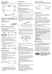
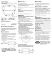
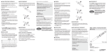
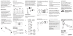
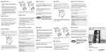
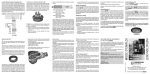
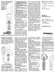
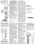
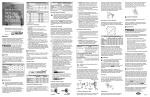
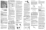
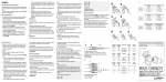
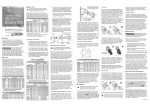
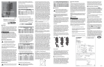
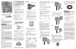
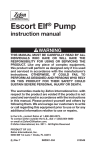
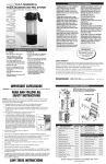
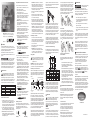
Crimped/Soldered Terminal Wire Connections: For 18-16 AWG Wires, the Ferrule is required: OPERATING INSTRUCTIONS DS & DSN MULTIPIN INSDSDSNMULTI G Meltric Corporation / 4640 Ironwood Drive Franklin, WI 53132 Tel. : 800 433 7642 / Fax : 414 817 6161 / e-mail : [email protected] A manufacturer of products using Marechal technology meltric.com 1. Strip each conductor to 25/64-inches (10-mm). 2. Insert Ferrule into contact. 3. Insert stripped wire end into Ferrule. (Perform either step 4 or 5) 4. For Crimping the Contacts, use either North American Contact Crimping Tool 4CN30 (using crimping slot 12-10) or Crimp contact with European Contact Crimping Tool 61-CA500 (using 4 MM slot). 5. NOTICE: Soldering of the wire into the contact must be performed with the contact out of the Interior Insulator to prevent damage to the insulator. • Using tin solder and a 50W soldering iron, heat the terminal for approximately 30 seconds. While heating, apply the soldering wire into the hole at the bottom of the terminal and let it penetrate by capillary action. Let it cool down without any mechanical stress. 6. Slide the Heat Shrink Insulation Sleeve over the contact until it butts up against the contact shoulder. NOTICE: Sleeve must be applied to maintain creepage and clearance distance. Please see picture. GENERAL DS and DSN Multipin products are used for power and control. They can carry loads as well as low level signals and information. DS and DSN Multipin devices comply with applicable IEC standards. Please follow the instructions below to ensure the proper installation, operation and maintenance of this product. are inherent dangers WARNING There associated with electrical products. Failure to follow safety precautions can result in serious injury or death. These instructions must DANGER be followed to ensure the safe and proper installation, operation and maintenance of the Meltric devices. CAUTION Before installation, disconnect all sources of power to the circuit to eliminate the risk of electrical shock. NOTICE INSTALLATION DS and DSN Multipins should be installed by ADVERTENCIA qualified electricians in accordance with all applicable local and national electrical codes. DANGER CAUTION WARNING AVISO DANGER Before starting, verify that the power is off, that the product ratings are appropriate for the application, and that the conductors meet code requirements and are within the capacities of the terminals noted in Table 1. Table 1 - Wiring Terminal Capacity1 (in AWG) Main Contacts Device Minimum Maximum DSN24c 18 14 DSN37c 18 14 DS24c 18 14 DS37c 18 14 1 CAUTION NOTICE Capacity is based on THHN wire sizes 7. With a Heat Gun that has a temperature range of 600°F to 950°F, apply heat evenly 360° around the sleeve until it shrinks around the contact and wire. For 14 AWG Wires (Max), the Ferrule is not required: 1. Strip each conductor to 25/64-inches (10-mm). 2. Insert wire into contact. (Perform either step 3 or 4) 3. For Crimping the Contacts, use either North American Contact Crimping Tool 4CN30 (using crimping slot 8) or Crimp contact with European Contact Crimping Tool 61-CA500 (using 4 MM slot). 4.NOTICE: Soldering of the wire into the contact, must be performed with the contact out of the Interior Insulator to prevent damage to the insulator. • Using tin solder and a 50W soldering iron, heat the terminal for approximately 30 seconds. While heating, apply the soldering wire into the hole at the bottom of the terminal and let it penetrate by capillary action. Let it cool down without any mechanical stress. 5. Slide the Heat Shrink Insulation Sleeve over the contact until it butts up against the contact shoulder. NOTICE: Sleeve must be applied to maintain creepage and clearance distance. Please see picture. 3. NOTICE: Meltric threaded handles come with tapered style threads. The use of fitting seal tape is recommended to maintain watertightness of all NPT fittings and joints. Disassembly of Contacts 1. To remove the contact from the insulating block, the provided Multi-Contact Removal Tool 9-LD12-37 must be used. From the front side of the insulating block, slide the contact removal tool over the contact. 2. Push until the contact pops out the back side of the insulating block. 3.NOTICE: Each contact is designed to be removed from the insulating block a maximum of 3 times. New contacts should be used if contacts are removed more than 3 times. Voltage Labels 6. With a Heat Gun that has a temperature range of 600°F to 950°F, apply heat evenly 360° around the sleeve until it shrinks around the contact and wire. Assembly of Contacts Once wired, the contacts must be inserted into the rear of their respective insulating block. The rear side of the inlet/plug or receptacle/connector is considered as the flat surface of the 4-bolt hole mounting surface. AssemblyDisassembly Adjust the cable location so that it will not be under tension inside the handle and tighten the compression nut to secure the cable. Assembly for In-Line Connections When DS and DSN Multipins are used as in-line connectors, finger drawplates should be installed on both the receptacle and plug in order for the user to more easily provide the leverage required to connect the device. Bushing Compression Nut Finger Drawplate Gasket Finger Drawplate Handle Color-Coded Gasket Receptacle (or Inlet) MAINTENANCE inspecting, repairing, WARNING Before or maintaining Meltric products, disconnect electrical power to the receptacle to eliminate the risk of electrical shock. DANGER Meltric products require little on-going maintenance. However, it is a good practice to periodically perform CAUTION the following general inspections: • Check the mounting screws for tightness. NOTICE • Verify that the weight of the cable is supported by the strain relief mechanism and not by the terminal connections. ADVERTENCIA In applications where DS and DSN receptacles (or inlets) are mounted to wall boxes, panels or other equipment, optimal operation is achieved when the device is installed with the latch at the top. For DS receptacles, mount device so one latch is at the top. Insert the cable or wires through the wall box and cut to allow adequate length, strip the cable sheath as desired, strip the individual wires to 25/64”, and twist the strands of each conductor together. Assemble the receptacle (or inlet) and the color-coded gasket to the box with the appropriate hardware. Assemble the mating plug (or receptacle) to the cord end as indicated in the assembly instructions above for in-line connections, except there will be no finger drawplate or associated black gasket. In applications where custom mounting to a panel or box is being performed, the clearance and mounting holes should be drilled as indicated in the following diagram and Table 2. B Disconnection To break the connection, simply depress the pawl as shown in figure 3 . This will break the circuit and eject the plug straight out to the rest, or off, position. The plug contacts are de-energized at this point. To remove the plug, rotate it counter-clockwise (about 30°) until it releases from the receptacle as shown in figure 4 . Close and latch the lid on the receptacle. Table 2 - Custom Mounting Dimensions ‘A’ ‘B’ Model DSN24c DSN37c DS24c DS37c Inches 2.25 2.50 2.25 2.50 C mm Inches mm Inches mm 57 1.89 48 .19 5 64 2.17 55 .19 5 57 1.89 48 .19 5 64 2.17 55 .19 5 NOTICE: In order to maintain the NEMA 4X or IP 66 & 67 protection provided by DSN models in custom installations, watertight seals should be used under the heads of the four mounting bolts and they must be retained by a lock washer and nut on the inside of the box or panel. Alternatively, four blind holes may be drilled and threaded to accommodate the mounting screws, provided that the hole depth is sufficient to achieve adequate gasket compression. Adjust the bushing diameter to fit the cable by removing inner sections of it as required. Insert the bushing into the strain relief, then insert the assembly into the handle and loosely install the compression nut. Insert the cable through the handle, the thin black drawplate gasket and finger drawplate (if applicable) and the color coded gasket. Strip the cable sheath to provide a workable wire length, being mindful that the sheath must extend into the handle to achieve a secure cord grip. Then strip the individual wires to 25/64” and twist the strands of each conductor together. OPERATION Verify that the cable sheath extends beyond the strain relief and into the handle. Assemble the receptacle (or inlet), the color coded gasket, the finger drawplate, and the thin black drawplate gasket to the handle with the four self-tapping screws provided. To connect a plug and receptacle, first depress the pawl to open the lid on the receptacle, then orient the plug as shown in figure 1 so that the red dot on the outside of the casing lines up with the red dot just to the left of the latch on the receptacle casing. To ensure safe and reliable operation Meltric plugs and receptacles must be used in accordance with their assigned ratings. They can only be used in conjunction with mating receptacles or plugs manufactured by Meltric or another licensed producer of products bearing the TM technology trademark. WARNING DANGER CAUTION NOTICE Connection and Disconnection of Stainless Steel DS 1. The stainless steel DS utilizes two pawls to latch the plug to the receptacle. Thus to disconnect the plug from the receptacle both pawls must be depressed. B Connection Receptacle contacts may be inspected by a qualified electrician. This should only be done with the power off. If any significant pitting of the contacts or other serious damage is observed, the device should be replaced. Deposits of dust or similar foreign materials can be rubbed off the contacts with a clean cloth. Meltric recommends regular cleaning of contacts in low voltage applications. If a cleaning spray is used, it should be a fast evaporating, non-conductive type that doesn’t leave a residue and is compatible with plastics. Operation of the stainless steel DS is similar to the standard DS/DSN operation with the following two exceptions: A C DANGER • Verify the electrical continuity of the ground circuit. CAUTION • Check the contact surfaces for cleanliness and pitting. AVISO • Check the IP gaskets for wear and resiliency. Replace as required. Hole Pattern for Custom Mounting WARNING: For safety reasons, it is always recommended to use a ground wire. Please reference your local codes for specific electrical requirements. WARNING DANGER CAUTION NOTICE Push the plug partially into the receptacle until it hits a stop, then rotate the plug in the clockwise direction until it hits another stop after about 30° of rotation. At this point, the circuit is still open. Push the plug straight into the receptacle as shown in figure 2 until it becomes securely latched in place. The electrical connection is now made. On in-line connectors, squeeze the drawplates on both sides of the device together until the plug latches in place. Assembly for Mounted Receptacles (or Inlets) Always have a qualified electrician complete the installation and apply one of the supplied voltage labels that best describe the voltage application level. Strain Relief General Notes & Precautions 1.Self-tapping screws are provided for use with some polymeric accessories. High torque may be required to drive them in. NOTICE: Once they are seated, care should be taken in order to avoid over-tightening them against the plastic material. 2. Various handles and cord grip options may be used. These instructions are based on handles provided with integral multi-layer bushing cord grips. 1.NOTICE: Before insertion of a contact into an insulator, please review the insulator’s contact numbering scheme so the ground and each contact (phase) is placed into the proper hole. 2. Push the wired contact into the insulating block until it stops and snaps into place. 3. Ensure its correct mounting by slightly pulling on the contact. 4. The male contacts are solid for their entire length and are inserted with the contact tip first into the rear of the inlet/plug. 5. The female contacts consist of a flexible braid and spring and are inserted with the contact tip first into the rear of the lidded receptacle/connector. 6. Insert the Provided Hole Plugs into the unused holes in the front of each insulating block. NOTICE: If a new Receptacle or Inlet is to mate with a previously installed device, pay particular attention to the number of contacts and numbered position in the Receptacle or Inlet. Continuity will not be obtained unless the male and female contacts are appropriately mated. 2. The stainless steel DS24c plug casing does not have a red dot that can be used for proper alignment before insertion. Instead, the thicker groove in the plug casing should be aligned with the thicker protruding screw in the receptacle and the thinner groove should be aligned with the thin protruding screw. 3. The stainless steel DSN37c casings do not utilize red dots for alignment. For proper alignment before insertion, align the arrow on the plug with the “off” position on the receptacle. ACHIEVING RATED WATERTIGHTNESS Rated ingress protection applies to the device when the plug and receptacle are mated and latched together. It also applies to the receptacle when the lid is latched closed. MANUFACTURER’S RESPONSIBILITY Meltric’s responsibility is strictly limited to the repair or replacement of any product that does not conform to the warranty specified in the purchase contract. Meltric shall not be liable for any penalties or consequential damages associated with the loss of production, work, profit or any financial loss incurred by the customer. Meltric Corporation shall not be held liable when its products are used in conjunction with products not TM bearing the technology trademark. The use of Meltric products in conjunction with mating devices TM that are not marked with the technology trademark shall void all warranties on the product. Meltric Corporation is an ISO 9001 certified company. Its products are designed, manufactured and rated in accordance with applicable UL, CSA and IEC standards. Meltric is also a member of BECMA, the international Butt-contact Electrical Connectors Manufacturers’ Association. Like all members, Meltric additionally designs and manufactures its products in accordance with BECMA standards established to ensure intermatablility with similarly rated products manufactured by other members. NOTICE: Meltric threaded handles come with tapered style threads. The use of fitting seal tape is recommended to maintain watertightness of all NPT fittings and joints. Lockout Provisions Poly DS and DSN receptacles may be purchased with optional lockout provisions. To lockout the receptacle, close and latch the lid and then attach the locking device through the optional hole provided in the pawl. This will prevent the lid from being opened for the insertion of a plug. NOTICE: Attaching the receptacle locking device with the receptacle lid open will not prevent the insertion of a plug. Lockout of the receptacle is only accomplished when the lid is locked closed. www.becma.ch INSDSDSNMULTI G Terminales Para Conductores Tipo Compresión o Soldables: Para cables 18-16 AWG, use una Zapata Tipo Casquillo: INSTRUCCIONES DE OPERACIÓN MULTIPIN DS Y DSN INSDSDSNMULTI G Meltric Corporation / 4640 Ironwood Drive Franklin, WI 53132 Tel. : 800 433 7642 / Fax : 414 817 6161 / e-mail : [email protected] A manufacturer of products using Marechal technology WARNING GENERALIDADES DANGER Los dispositivos DS y DSN Multipin, son usados para fuerza y control. Pueden manejar perfectamente cargas yCAUTION señales de bajo nivel e información. Los dispositivos Multipin DS y DSN cumplen con las normas IEC aplicables. Certificados CE están disponibles bajo pedido. NOTICE meltric.com ADVERTENCIA Hay peligros inherentes con los productos eléctricos. El no seguir las precauciones de seguridad puede resultar en lesiones graves o muerte. Seguir estas instrucciones para garantizar una segura y apropiada instalación, uso y mantenimiento de los productos Meltric. Antes de instalar desconecte todas las fuentes al circuito para eliminar el riesgo al shock eléctrico. DANGER CAUTION AVISO INSTALACIÓN Los Multipin DS y DSN deben ser instalados por un electricista calificado, de acuerdo a las normas eléctricas nacionales y locales aplicables. Antes de iniciar, verifique que el circuito esté desenergizado, que rango del producto es el apropiado para la aplicación y que los conductores cumplan con la normatividad vigente y se encuentren dentro de la capacidad de las terminales que se mencionan en la tabla 1. WARNING DANGER CAUTION NOTICE Tabla 1 -Capacidad de alambrado en las terminales (en AWG1) Contactos de Principales Dispositivo Mínimo Máximo DSN24c 18 14 DSN37c 18 14 DS24c 18 14 DS37c 18 14 1 Capacidad basada en conductores THHN Notas y Precauciones Generales 1. AVISO: Se proporcionan tornillos autorroscantes para ser utilizados con algunos componentes poliméri cos, puede requerirse de un gran torque para insertarlos, una vez hecho esto, evite apretarlos demasiado contra el material plástico. 2. Se pueden usar varias opciones de manijas y sujetadores de cables, estas instrucciones están basadas en manijas que utilizan un sujetador para el cable tipo empaque multicapa. 3. AVISO: Todas las manijas de MELTRIC tienen roscas cónicas. El uso de cinta selladora, se recomienda para mantener la impermeabilidad de todos los accesorios y uniones NPT. 1. Retire el aislamiento de cada uno de los conductores 25/64” (10mm). 2. Inserte la zapata tipo casquillo en la terminal del contacto. 3. Inserte el conductor sin aislamiento dentro de la zapata tipo casquillo. (Ejecute uno de los pasos 4 ó 5) 4. Para comprimir las terminales de los contactos, use una herramienta de compresión para terminales Americanas 4CN30 (Use la ranura 12-10) o use una herramienta de compresión para terminales Europeas 61-CA500 (Use la ranura 4mm). 5. AVISO: Precaución: Soldar el conductor en la terminal, debe realizarse con la terminal fuera de la base de Aislamiento Interior del dispositivo, para evitar dañarlo. • Use soldadura de estaño y un cautín de 50 W, caliente la terminal por aproximadamente 30 segundos. Durante el calentamiento, aplique la soldadura en la perforación en la parte superior de la terminal y permita que penetre por acción capilar. Déjelo enfriar sin aplicar ningún esfuerzo mecánico. 6. Deslice la funda termocontráctil hasta que tope contra el hombro del contacto. AVISO: La funda deberá ser aplicada en el contorno del dispositivo para mantener el aislamiento. Ver fotografía. 7. Con una Secadora de Mano que tenga un rango de temperatura de 600o F hasta 950o F, aplique calor uniformemente 360o alrededor de la funda hasta que se encoja sobre el contacto y el conductor. Para conductores calibre 14 AWG (Max.), la zapata tipo casquillo no se requiere: 1. Retire el aislamiento de cada uno de los conductores 25/64” (10mm). 2. Inserte el conductor sin aislamiento dentro de la terminal del contacto. (Ejecute uno de los pasos 4 ó 5) 3. Para comprimir las terminales de los contactos, use una herramienta de compresión para terminales Americana 4CN30 (Use la ranura 8) o use una herramienta de compresión para terminales europea 61-CA500 (Use la ranura 4mm). 4.AVISO: Soldar el conductor en la terminal, debe realizarse con la terminal fuera de la base de Aislamiento Interior del dispositivo, para evitar dañarlo. • Use soldadura de estaño y un cautín de 50 W, caliente la terminal por aproximadamente 30 segundos. Durante el calentamiento, aplique la soldadura en la perforación de la parte superior de la terminal y permita que penetre por acción capilar. Déjelo enfriar sin aplicar ningún esfuerzo mecánico. 5. Deslice la funda termo contráctil hasta que tope contra el hombro del contacto. AVISO: La funda deberá ser aplicada en el contor no del dispositivo para mantener el aislamiento. Ver fotografía. por la parte trasera que corresponda de la base aislante. La parte trasera del tomacorriente o la clavija es considerada como la superficie plana con 4 orificios para tornillos de montaje. EnsambleDesensamble 1.AVISO: Antes de insertar un contacto en la base aislante, favor de revisar el esquema de numeración de los contactos en la base aislante, de forma que el contacto de tierra y todos los contactos se coloquen en el orificio correcto. 2. Empuje el contacto cableado en la base aislante hasta que asiente y se asegure en su lugar. 3. Asegúrese que el contacto se instaló correctamente, tirando levemente de él. 4. Los contactos macho son sólidos en toda su extensión y se insertan con la punta del contacto primero en la parte trasera de la clavija. 5. Los contactos hembra consisten de una trenza flexible y un resorte y son insertados con la punta del contacto primero en la parte trasera del tomacorriente con tapa. 6. Inserte los tapones proporcionados en cada orificio no utilizado por la parte frontal de la base aislante. AVISO: Si un nuevo tomacorriente o clavija es conectado a un dispositivo existente, ponga particular atención al número de contactos y su posición numerada, en el tomacorriente o clavija. La continuidad no se obtendrá a menos que todos los contactos macho y hembra, estén acoplados de manera uniforme.. Desensamble de Contactos 1. Para remover los contactos de la base aislante, deberá de utilizar la Herramienta de Extracción Multi-Contact 9-LD-12-37. Por la parte frontal de la base aislante, deslice la herramienta de extracción en el contacto. 2. Presione hasta que el contacto salga por la parte trasera de la base aislante. 3.AVISO: Cada contacto está diseñado para ser removido un máximo de 3 veces. Se deberán de usar contactos nuevos si son removidos por más de 3 ocasiones. Etiquetas de Voltaje Se recomienda que un electricista calificado haga la instalación y que aplique una de las etiquetas de voltaje que se suministran de acuerdo con el nivel de voltaje de la aplicación. WARNING DANGER CAUTION NOTICE empaque multi capa Relevador de esfuerzo Tuerca de compresión Empaque para placa de cierre con los dedos Placa de cierre con los dedos Manija Empaque de Tomacorriente codificado por (o clavija) color 6. Con una secadora de mano que tenga un rango de temperatura de 600º F a 950º F, aplique uni formemente 360o F alrededor de la funda hasta que se encoja sobre el contacto y el conductor. Cuando los dispositivos DS y DSN son usados como extensión, se pueden instalar las placas de cierre con los dedos tanto en el tomacorriente como en la clavija, con el fin de que el usuario pueda tener la palanca necesaria, para cerrar fácilmente el dispositivo. Ensamble de Contactos Ajuste el diámetro del Empaque Multicapa retirando cada una de las mismas según se requiera. Inserte el Empaque en el Relevador de Esfuerzos y luego colóquelo en la manija e instálelo sin apretar la Tuerca de Compresión. Inserte el cable a través de la manija, el utilizar de acuerdo con sus capacidades. Solo pueden utilizarse en conjunto con tomacorrientes y clavijas MELTRIC u otro fabricante autorizado de los productos con TM la tecnología registrada technology trademark. Conexión Para conectar un tomacorriente y clavija, primeramente presione el botón rojo en el gatillo para abrir la tapa del tomacorriente, luego oriente la clavija como se muestra en la figura 1, de tal manera que el punto rojo en la parte exterior de la clavija este alineado con el punto rojo a la izquierda del gatillo en el tomacorriente. Empuje la clavija parcialmente en el tomacorriente hasta que llegue al tope, entonces gire la clavija en dirección de las manecillas del reloj hasta que llegue al tope después de girar aproximadamente 30o. En este punto el circuito está abierto. Empuje la clavija contra el tomacorriente, como se muestra en la figura 2 hasta que este asegurada en su lugar. Ahora el circuito eléctrico está cerrado. En aplicaciones tipo extensión, apriete las placas de cierre con los dedos en ambos lados del dispositivo, hasta que la clavija que se asegure en su lugar. Verifique que la cubierta del cable se extiende más allá del relevador de esfuerzos y dentro de la manija. Ensamble el tomacorriente o clavija, el empaque codificado por color, la placa de cierre con los dedos y el empaque negro delgado con la manija, usando los cuatro tornillos autorroscantes proporcionados.. Ajuste la posición del cable para que no quede bajo tensión dentro de la manija, y apriete la tuerca de compresión para asegurar el cable. Ensamble de Tomacorriente o Clavija en Caja de Conexiones En aplicaciones en donde los tomacorrientes (o clavijas) DS y DSN son instaladas en cajas de conexiones para montaje en pared, tableros u otro equipos, la operación optima se logra cuando el gatillo se instala en la parte superior. Inserte el cable o conductores a través de la caja y corte permitiendo un largo adecuado, remueva el aislamiento individual de los conductores 25/64” (10mm). Y tuerza los hilos de cada conductor. Ensamble el tomacorriente (o clavija) y el empaque codificado por color en la caja, con los tornillos adecuados. Ensamble la clavija (o tomacorriente) al final del cable, como se indica en las instrucciones para el ensamble tipo extensión, excepto la placa de cierre con los dedos y el empaque negro delgado. Desconexión Para desconectar, simplemente presione el botón rojo en el gatillo como se muestra en la figura 3. Esto abrirá el circuito y expulsará la clavija hasta su posición de descanso o fuera. En este punto los contactos de la clavija estarán desenergizados. Para remover gire la clavija en sentido contrario a las manecillas del reloj (cerca de 30º) hasta removerla del tomacorriente, como se muestra en la figura 4. Cierre la tapa y asegúrela al tomacorriente. Dimensiones de Barrenos para Montaje Especial En aplicaciones donde se realizará un montaje especial a en tablero o caja, los barrenos y la distancia entre ellos deberán de hacerse de acuerdo con el diagrama y la Tabla 2. B DS de Acero Inoxidable Conexión y Desconexión ADVERTENCIA: Por razones de seguridad, siempre se recomienda usar un conductor a tierra. Refiérase a la Norma Local para los requisitos eléctricos específicos. Ensamble de Tomacorrientes Tipo Extensión Una vez cableados, los contactos se deben insertar empaque negro delgado, la placa de cierre con los dedos (si es necesario) y el empaque codificado por color. Remueva el aislamiento del cable para proveer un área de trabajo adecuada, teniendo en cuenta que la cubierta del cable debe de quedar dentro de la manija, para asegurar el cable con el conector glándula. Remueva el aislamiento individual de los conductores 25/64” 10mm. Y tuerza los hilos del conductor. A C La operación del DS de Acero Inoxidable es similar a la operación del DS/DSN estándar con las siguientes excepciones: B Dimensiones de Barrenos para Montaje Especial ‘A’ ‘B’ C Modelo DSN24c DSN37c DS24c DS37c Pulgadas mm Pulgadas mm Pulgadas mm 2.25 2.50 2.25 2.50 57 64 57 64 1.89 2.17 1.89 2.17 48 55 48 55 .19 .19 .19 .19 5 5 5 5 AVISO: Para mantener la protección NEMA 4X o IP66/67 en los dispositivos DSN en Instalaciones especiales, se deberán utilizar de sellos a prueba de agua en las cabezas de los cuatro tornillos de montaje y deben ser retenidos por una rondana de presión y una tuerca en el interior de la caja de conexiones o tablero. Alternativamente 4 barrenos ciegos pueden ser taladrados y/o roscados para insertar los 4 tornillos de montaje. OPERACIÓN Para garantizar una operación segura y confiable, los tomacorrientes y clavijas MELTRIC, se deberán de 1. En los DS de Acero Inoxidable se utilizan dos gatillos para asegurar la clavija en el tomacorriente. Por lo consiguiente para desconectar la clavija del tomacorriente, hay que presionar los botones de los dos gatillos. 2. Los envolventes del DS24c de Acero Inoxidable no tienen puntos rojos de guía para alinearlos apropiadamente antes de insertarlos. En su lugar, la ranura más gruesa del envolvente de clavija deberá de alinearse con el tornillo grueso que sobresale en el tomacorriente y la ranura más delgada del envolvente de la clavija deberá de alinearse con el tornillo delgado que sobre sale en el tomacorriente. 3. El envolvente del DS37c de Acero Inoxidable no utiliza puntos rojos para alineación. Para una alineación adecuada antes de la inserción, alinee la flecha en la clavija con la posición “off” del tomacorriente. ente cuando la tapa está asegurada con el gatillo. AVISO: Las manijas roscadas Meltric tienen cuerdas cónicas. El uso de cintas selladoras se recomienda, para mantener la protección ambiental en todas las conexiones y uniones tipo NPT. Accesorios para Bloqueo Los tomacorrientes poliméricos DS y DSN se pueden comprar con una provisión de bloqueo opcional. Para bloquear el tomacorriente, cierre y asegure la tapa y inserte el dispositivo de bloqueo a través del orificio porporcionado en el gatillo. Esto evita que la tapa se pueda abrir para insertar la clavija. WARNING DANGER CAUTION NOTICE MANTENIMIENTO AVISO: La colocación de un candado en el tomacorriente con la tapa abierta, no evitará la inserción de una clavija. El bloqueo del tomacorriente solo se logra cuando la tapa está cerrada. Antes de inspeccionar, reparar o mantener los productos Meltric, desconecte la alimentación al tomacorriente para eliminar el riesgo del shock eléctrico. ADVERTENCIA DANGER Los productos Meltric requieren de muy poco manCAUTION tenimiento, de cualquier manera es recomendado que se realicen las siguientes prácticas de inspección AVISO general: • • • • • Revise el apriete de los tornillos de montaje. Verifique que el peso del cable esté soportado en el relevador de esfuerzos y no en las terminales de conexión. Revise el desgaste y ajuste del empaque IP. Intercámbielo si se requiere. Verifique la continuidad eléctrica del circuito de tierra. (se recomienda cada 6 meses). Revise la limpieza y desgaste de la superficie de los contactos. Los contactos del tomacorriente pueden ser inspeccionados únicamente por un electricista calificado. Esto solo podrá hacerse con el equipo desenergizado. Si hay un desgaste severo en los contactos o cualquier otro daño serio, el dispositivo deberá de ser reemplazado. Depósitos de polvo o materiales ajenos pueden ser limpiados con un trapo limpio. Meltric recomienda la limpieza periódica de los contactos en aplicaciones de bajo voltaje. Si se usa aerosol de limpieza, deberá de asegurarse que sea de evaporación rápida, de tipo no conductivo y no deberá de dejar ningún residuo y deberá ser compatible con plásticos. RESPONSABILIDAD DEL FABRICANTE La responsabilidad de Meltric está limitada estrictamente a la reparación y o reemplazo de cualquier producto que no cumpla con la garantía especificada en el contrato de compra. Meltric no puede ser responsabilizado por fallas, daño a consecuencia de la perdida de producción o cualquier perdida financiera en la que incurra el cliente. Meltric Corporation no puede ser responsabilizado cuando sus productos son utilizados en conjunto con otra marca TM que no tenga la marca registrada . El uso de dispositivos acoplables que no tengan la marca registrada TM invalidara toda garantía en el producto. Meltric Corporation es miembro de la asociación internacional BECMA ; Asociación de Fabricantes de Conexiones Eléctricas Punto a Punto. www.becma.ch RANGO DE PROTECCIÓN CONTRA INGRESO DE AGUA El rango de protección contra ingreso de agua se alcanza, cuando el tomacorriente y la clavija estén acoplados y asegurados. También aplica al tomacorri- INSDSDSNMULTI G