1
ATTENTION : NE PAS FAIRE FONCTIONNER LES
PROJECTEURS HORS DE L'EAU
1B
1V
2
3
4
6
13+7
PROJECTEUR HALOGENE 75 W - série 342xxxx
75 WATT HALOGEN PROJECTOR - serial 342xxxx
CARACTERISTIQUES TECHNIQUES
Le projecteur doit éclairer dans le sens opposé à la maison ou à la
terrasse pour ne pas géner par un éclairage trop fort.
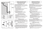
Le projecteur doit être positionné à 30 cm. au maximum sous la
margelle depuis l’axe de l’ampoule.
La niche du projecteur est pourvue d'une sortie 3/4".
L'étanchéité de la sortie et de la gaine sera réalisée dans les règles de
l'art au niveau de la boite de connexion.
75 W - 12 V - AC / Utiliser un transformateur de sécurité avec un
secondaire > ou égal à 100 VA sous 12 V. AC
TECHNICAL CHARACTERISTICS
Point the projector away from the house or terrace, so as not to create
an excessively bright illumination.
The projector should not be positioned more than 30 cm under the
coping, as measured from the centre of the bulb.
The niche of the projector has a 3/4’’ outlet.
Seal the outlet and the flexible conduit in accordance with normal
working practice at the connection box.
75 W - 12 V - AC / Use a safety transformer with an output greater than
or equal to 100 VA at 12 V. AC
STRUCTURE MACONNÉE LINER
•
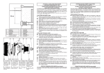
Sceller la traversée de paroi du projecteur (réf.3353) dans la
maçonnerie en prévoyant de finir l'enduit à fleur de la face avant.
•
Visser la gaine sur la niche du projecteur en réalisant l'étanchéité.
•
Visser l'ensemble dans la traversée de paroi en réalisant une autre
étanchéité.
•
Poser le joint sur la face avant de la niche du projecteur.
•
Poser le joint sur la bride de la niche du projecteur.
•
Fixer la bride d'étanchéité après la pose du liner.
•
Découper le liner à l’interieur de la niche.
•
Aiguiller le cable de l'optique du projecteur dans la gaine jusqu'à la
boite de connexion (réf.3495ECO)
•
Présenter l'optique devant la niche en remontant le cable dans la
boite de connexion, et cliper l'optique sur la niche.
•
Remonter et enrouler le cable dans la boite de connexion et réaliser
l’étanchéité au niveau de la boîte.
30 cm
PRHX7010
PRHX7009
PRHX20029
PRHX20030
PRHX20024
PRHX20019
PRHX20115
8
9B
9V
10
11
12
14
PRHX9470
PRHX9474
PRHX9475
BR2XVS
PRHX20023
PRHX20022C
PRX20018
STRUCTURE PANNEAUX LINER
•
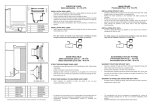
Effectuer un perçage de 110 mm dans le panneau
•
Poser la niche du projecteur par l’intérieur du bassin. Visser l'écrou
arrière (réf.3492) pour la maintenir en place.
•
La réalisation de l’étanchéité du liner, de la gaine et la pose de
l'optique du projecteur sont identiques au projecteur liner.
STRUCTURE MACONNÉE SANS LINER
•
Sceller la traversée de paroi (réf.3352) dans la maçonnerie en
prévoyant de finir l'enduit ou le carrelage à fleur de la face avant.
•
Visser la niche du projecteur dans la traversée de paroi.
•
La réalisation de l'étanchéité de la gaine et la pose de l’optique du
projecteur sont identiques au projecteur liner.
BOITE DE CONNEXION (REF. 3495ECO) (non fournie)
Raccorder la gaine du projecteur à la sortie 3/4" située sur le fond de la
boite de connexion en réalisant une étanchéité. Utiliser les blocs de
jonctions fournis avec les boites de connexion pour raccorder le
projecteur à l’alimentation en torsadant les fils et serrant bien les vis des
bornes de jonctions.
Informations indicatives, représentations “photos & schémas” non contractuelles.
WARNING! DO NOT ATTEMPT TO USE THESE
PROJECTORS OUT OF WATER
MAINTENANCE DU PRODUIT
Le remplacement de pièces doit être effectué avec des pièces d’origines.
Lors d’un changement d’ampoule et/ou du câble, il est préconisé de
changer la totalité des pièces assurant l’étanchéité. Type de lampe
utilisé : EYC/CC en cas de nécessité de changement de la lampe,
utiliser la pièce d’origine.
•
Le fabricant ne pourra être tenu pour responsable d’un dommage
direct ou indirect provenant d’une utilisation ou installation
incorrecte du produit.
•
Informations indicatives, représentations, photos et schémas non
contractuels.
LINER MASONRY STRUCTURE
•
Seal the projector wall fitting (ref 3353) into the masonry, taking the
necessary steps to ensure that you can subsequently apply
finishing rendering around the front panel.
•
Screw the flexible conduit onto the niche of the projector, ensuring
that there is a waterproof seal.
•
Screw the entire assembly into the wall fitting, ensuring that there is
a waterproof seal.
•
Fit the seal onto the front panel of the niche of the projector.
•
Fit the seal onto the projector’s niche flange.
•
After installing the liner, secure the sealing flange.
•
Make a cut-out in the liner within the fixed part.
•
Thread the projector’s lighting unit cable through the flexible
conduit up to the connection box (ref 3495ECO).
•
Hold the lighting unit in front of the mounting, and coil-up the cable;
then clip the lighting unit onto the niche.
•
Roll-up the cable and put it in the connection box and proceed with
sealing the connection box.
LINER PANELLING STRUCTURE
•
Cut a hole 110 mm wide in the panel.
•
Install the projector’s niche from within the basin. Fit the rearnut (ref
3492) in order to maintain it in position.
•
Proceed with sealing the liner, cable and flexible conduit, and install
the projector’s lighting unit, in the same way as for the liner projector.
MASONRY STRUCTURE WITHOUT LINER
•
Seal the wall fitting (ref 3352) into the masonry, taking the
necessary measures to ensure that you can subsequently apply
finishing rendering or tiling around the front panel.
•
Screw the projector’s niche into the wall fitting.
•
Proceed with sealing the liner, cable and flexible conduit, and install
the projector’s lighting unit, in the same way as for the liner projector.
CONNECTION BOX (REF 3495ECO) (not provided)
Connect the projector’s flexible conduit to the 3/4’’ outlet located on the
bottom of the connection box ensuring that there is a waterproof seal.
Use the connector blocks provided with the juction box to connect the
spotlight to the power supply by twisting the wires and ensuring that the
terminal screws are well tightened.
PRODUCT MAINTENANCE
Original components must be used in all replacement operations.
When changing a bulb and/or cable, it is recommended that all
components be changed to avoid compromising the seals. Type of light
used : EYC/CC, in the event of necessity changing of the light, to use
original part.
•
The manufacturer can not be considered as responsible for a direct
or indirect damage resulting from an use or an incorrect installation
of the product.
•
Indicative information, not contractual photos and schema.
ATENCION: NO ENCENDER LOS PROYECTORES
FUERA DEL AGUA
PROYECTOR HALOGENO 75 W - série 342xxxx
HALOGEN-SCHEINWERFER 75 W - serie 342xxxx
CARACTERISTICAS TECHNICAS
EI proyector debe iluminar en el sentido opuesto a la casa o terraza para
no deslumbrar.
El proyector debe situarse a 30 cm como maximo por debajo de la
piedra de coronación desde el eje de la bombilla.
El nicho del proyector esta provisto de una salida de 3/4".
La hermeticidad de la salida y la funda se realizara segun las reglas del arte.
75 W - 12 V - AC / Utiliza un transformador de seguridad con un
secundario > o igual a 100 VA y 12 V
TECHNISCHE DATEN
Der Scheinwerfer soll in dem Haus oder der Terrasse
gegenüberliegender Richtung leuchten, um keine Störung durch zu
starke Beleuchtung zu verursachen.
Der Scheinwerfer mub höchstens 30 cm unter der Einfassung ab der
Glühbirnenachse angebracht werden.
Die Nische des Projektors ist mit einem Ausgang 3/4’’ ausgerüstet.
Die Dichtheit des Ausgangs und der Kabelschutzrohr ist fachgerecht zu
gewährleisten.
Technische daten : 75 W - 12 v - AC / Einen Sischerheitstransformator
mit einer Sekundärwicklung 100 VA / 12 V oder entsprechend benutzen
ESTRUCTURA C0NSTRUIDA EN LINER
•
Sellar el pasamuro del proyector (réf. 3353) en la construcción
previniendo embaldosar o revestir la piscina coincidiendo con la
parte delantera
•
Entornillar la funda en el nicho del proyector realizando la
hermeticidad
•
Entornillar el conjunto en el pasamuro realizando otra hermeticidad
•
Poner la junta en la parte delantera del nicho del proyector
•
Poner la junta en la brida del nicho del proyector
•
Fijarla brida de hermeticidad después de poner el liner
•
Recortar el liner en el interior del nicho
•
Agujerear el cable del optico del proyector en la funda hasta la caja
de conexiones (ref.3495ECO) Situar el optico delante del nicho
remontando el cable en la caja de conexiones, y fijar el optico sobre
el broche de resorte
•
Tirar de y enrollar el cable en la caja de conexiones y realizar la
hermeticidad del caja de conexiones.
ESTRUCTURA PANEL LlNER
•
Hacer un agujero de 110 mm en el panel
•
Poner el nicho del proyector por el interior de la piscina. Atornillar la
tuerca de detras (ref.3492) para fijarla
•
La realizacion de la hermeticidad del liner, del cable de la funda y
la situacion del optico del proyector son idénticas a las del
proyector liner
ESTRUCTURA EN CONSTRUCCION SlN LINER
•
Sellar el pasamuro (ref.3352) a la construccion previniendo el
embaldosado revestimiento a la altura de la parte delantera
•
Atornillaar el nicho del proyector en eI pasamuro
•
La realización de la hermeticidad del liner, del cable de la funda y
la situacion del optico del proyector son idénticas a las del
proyector liner
CAJA DE CONEXlONES (Ref. 3495ECO) (no proporcionado)
Empalmar la funda del proyector en la salida 3/4’’ situada en la base de
la caja de conexiones realizando otra hermeticidad. Utilizar los bloques
de uniones suministrados con las cajas de conexiòn para conectar el
proyector a la alimentaciòn, torciendo los cables y apretando bien los
tornillos de los bornes de uniòn.
MANTENIMIENTO DEL PRODUCTO
El reemplazo de las piezas se debe efectuar con piezas originales.
Al cambiar una bombilla y/o un cable, se aconseja cambiar la totalidad
de las piezas que aseguran la estanqueidad. Tipo de làmpara utilizado
: EYC/CC. En caso de necesidad de cambio de la làmpara, utilizar la
parte de origen.
•
El fabricante no puede ser considerado como responsable de un
daño directo o indirecto que es resultado de un empleo o una
instalación incorrecta del producto.
•
Información indicativa, no esquera contractual.
PHVNOTICE - REV D - 07
ACHTUNG : DIE SCHEINWERFER NICHT AUSSERHALB
DES WASSERS EINSCHALTEN
PROJECTEUR HALOGENE 75 W
75 W HALOGEN UNDERWATER LIGHT
PROYECTOR HALOGENO 75 W
HALOGEN UNTERWASSER
SCHEINWERFER 75 W
Série - Serial - Serie - 342xxxx
MAUERSTRUKTUR LINER
•
Die Wandtraverse des Scheinwerfers (Ref. 3353) im Mauerwerk
verankern; dabei berücksichtigen, den Verputz schlüssig an der
Vorderseite abzuschließen.
•
Die Kabelschutzrohr an der Nische des Scheinwerfers
anschrauben, um die Dichtheit herzustellen.
•
Die Wandtraversen-Baugruppe anschrauben, um eine andere
Dichtheit herzustellen.
•
Die Dichtung an der Vorderseite der Scheinwerfernische anbringen.
•
Die Dichtung am Flansch der Scheinwerfernische anbringen.
•
Den Dichtungsflansch nach Verlegen des Liners befestigen.
•
Den Liner innerhalb der Nische ausschneiden.
•
Das Kabel der Scheinwerferoptik in die Stopfbuchse durch die Hülse
bis zum Abzuschließen (Ref. 3495ECO) Kabelschutzrohr führen.
•
Die Optik vor die Nische halten und das Kabel in den
Anschlußkasten führen ; die Optik an der Nische verclipsen.
•
Das Kabel in den Anschlußkasten führen und dort aufrollen und die
dichtheit des anschlusskasten.
PLATTENSTRUKTUR LINER
•
Die Platte 110 mm tief ausbohren.
•
Die Nische des Scheinwerfers von innen im Becken anbringen. Die
rückseitige Mutter (Ref. 3492) festschrauben, um sie festzuhalten.
•
Die Herstellung der Dichtheit des Liners, der Kabelschutzrohr und
die Anbringung der Scheinwerferoptik sind identisch mit dem LinerScheinwerfer.
MAUERSTRUKTUR OHNE LINER
•
Die Wandtraverse des Scheinwerfers (Ref. 3352) im Mauerwerk
verankern; dabei berücksichtigen, den Verputz oder die
Fliesenverlegung schlüssig an der Vorderseite abzuschließen.
•
Die Nische des Scheinwerfers in die Wandtraverse clipsen.
•
Die Herstellung der Dichtheit der Kabelschutzrohr und die Anbringung
der Scheinwerferoptik sind identisch mit dem Liner-Scheinwerfer.
ANSCHLUSSKASTEN (REF 3495ECO) (nicht geliefert)
Die Kabelschutzrohr des Scheinwerfers am Ausgang 3/4’’ am Boden
des Anzuschlußkastens anschließen, um die Dichtheit herzustellen.
Zum Anschließen des Scheinwerfers an die Stromversorgung die mit
dem Anschlusskasten gelieferten Reihenklemmen benutzen, wobei die
Drähte verdrillt und die Schrauben der Lüsterklemmen gut
festgezogen werden.
PRODUKTINSTANDHALTUNG
Zum Austauschen Originalteile benutzen.Beim Wechsel einer Glühbirne
und/oder des Kabels wird das Austauschen aller Dichtungsteile
empfohlen. Benutzter lampentyp: EYC/CC bei der lampe das
ursprungsstück zu benutzen.
•
Der Erzeuger wird keinen Verantwortlichen für eines direkten oder
indirekten Schadens gehalten sein können, der aus einer Benutzung
oder einer inkorrekten Einrichtung des Produktes verbindet.
•
Zum Info, nicht vertragliche Fotos und Schemas.
NOTICE D’UTILISATION
USER’S GUIDE
GUIA DEL USUARIO
ANWENDER HANDBUCH
HAYWARD POOL EUROPE
- P.I.P.A. - Allée des Chênes - 01150 Saint Vulbas - France