1
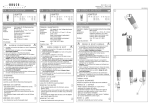
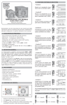
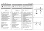
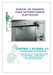
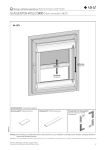
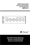
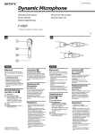
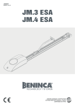
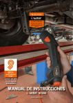
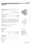
BRUCK GMBH & CO.KG
INDUSTRIESTR. 22 • 44628 HERNE
internet http://www.bruck.de
GEBRAUCHSANLEITUNG
D
VIA
N V- S C H I E N E N S Y S T E M
L I E F E R U M FA N G
D
ECKVERBINDER 45°
1 Eckverbinder 45°, komplett
ART.-NO. 160 411 ch
160 411 g
160 411 mc
1
ECKVERBINDER 45°
ID-NO.
130 667
130 674
142 189
Verbinder bis zum Anschlag in VIA-Schiene einstecken.
Wichtig! Schienenenden müssen sorgfältig entgratet und von Metallspänen
gereinigt sein, um Kurzschluß und Beschädigungen an den Federn
der Steckverbinder zu vermeiden.
TECHNISCHE DATEN
Beschreibung:
Systemspannung:
max. Belastung:
Material:
1
Verbinder zur horizontalen, leitenden 45°- Verbindung
von VIA-Kupferrohrschienen.
12 V
400 Watt
Stecker:
Zinkdruckguß, vernickelt / vergoldet /
matt-verchromt
Federn:
Kupferberyllium
Isolierung: Kunststoff, schwarz
ALLGEMEINE SICHERHEITSHINWEISE
1. Montage und Anschluß des Systems nur durch Fachpersonal (Elektriker).
2. Bei allen Arbeiten an System und Leuchten Anlage spannungsfrei
schalten!!
3. Nicht zur Installation in Feuchträumen geeignet.
4. Bei der Montage des VIA-Systems dürfen nur VIA-Systembauteile
verwendet werden.
5. Achtung, Gefahr durch Stromschlag !!
System und Leuchten niemals ohne Trafo direkt an die Netzspannung
anschließen!!
6. Es liegt in der Verantwortung des Benutzers, die elektrische, mechanische
und thermische Verträglichkeit zwischen dem System und
den daran angebrachten Leuchten sicherzustellen.
7. Vorsicht! Leuchte und Leuchtmittel werden in Betrieb heiß.
8. Den angegebenen Mindestabstand der Leuchtmittel zu brennbaren
Gegenständen beachten! ( siehe Leuchte
)
9. Keine Gegenstände über das System hängen:Kurzschluß und Brandgefahr!
10. Kein Garantieanspruch bei eigenmächtigen Veränderungen und oder
unsachgemäßer Benutzung!
VIA
LV TRACK SYSTEM
GB
C O R N E R C O N N E C TO R 4 5 °
ART.-NO. 160 411 ch
160 411 g
160 411 mc
ID-NO.
130 667
130 674
142 189
TECHNICAL CHARACTERISTICS
Description:
System voltage
Maximum wattage
Material:
connector for the horizontal, conducting 45°connection of VIA copper tube tracks.
12 V SELV
400 W
plug:
zinc pressure founding, nickle-plated /
gold-plated / mat-chromed
springs:
copper beryllium
insulation: plastic, black
131112983A
GENERAL REMARKS ON SAFETY
1. Assembly and connection of the system only by specialist personnel
(electrician).
2. Switch off power to the system for all work on the system and on lamps!!
3. Not suitable for installation in wet rooms.
4. For assembly of the VIA system, only VIA system components
must be used.
INSTRUCTIONS FOR USE
GB
5. Attention, electric shock hazard!!
Never connect the system and lamps without transformer directly to
the mains voltage!!
6. It is within the responsibility of the user to ensure the electrical,
mechanical and thermal compatibility between the system and lamps
mounted to it.
7. Take care! Lamp and illuminant become hot during operation.
8. Observe the stated minimum distance of the illuminants to flammable
)
D E Lobjects!
I V E R Y (Psee
A C lamp
KAGE
9. Do not hang objects over the system: Hazard of short circuit and
2 track connecters, complete
fire hazard!
10. No warranty claim in case of unauthorized modifications and / or
improper use!
DELIVERY PACKAGE
1 corner connector 45°, complete
C O R N E R C O N N E C TO R 4 5 °
Plug the connector into the VIA track up to the detention point.
Important!
The track ends must be carefully cleaned from burr and
metal rests in order to avoid short-circuit and damages
at the springs of the plug connectors.
1
VIA
SYSTÈME À BAS VOLTAGE
F
CONNECTEUR ANGULAIRE À 45°
ART.-NO. 160 411 ch
160 411 g
160 411 mc
ID-NO.
130 667
130 674
142 189
DATES TECHNIQUES
Description:
Voltage de système:
Rendement max.:
Matériaux:
Connecteur pour la connexion horizontale, linéaire et
conductrice de lignes tubulaires de cuivre VIA
12 V SELV
400 W
fiche:
fusion à pression de zinc, nicklé / doré /
chromé en mat
ressorts:
béryllium de cuivre
isolation: plastique, noir
4. En el montaje del sistema VIA solamente deben emplearse piezas
constructivas del sistema VIA.
5. ¡Atención peligro de electrocución!
¡El sistema y las lámparas no deben conectarse nunca directamente
a la tensión de red sin transformador!
6. Es responsabilidad del usuario asegurar la compatibilidad eléctrica,
mecánica y térmica entre el sistema y las lámparas empleadas en él.
7. ¡Cuidado! Las lámparas y las bombillas o reflectores se calientan
durante el funcionamiento.
8. ¡Ha de observarse la distancia mínima indicada de las bombillas o
reflectores respecto de los objetos combustibles! (véase la lámpara
9. No colgar ningún objeto por encima del sistema: ¡peligro de
cortocircuito y de incendio!
10. ¡Se pierden las reivindicaciones de garantía al llevar modificaciones
a cabo por propia cuenta y / o empleo incorrecto!
CONTENIDO DE LA ENTREGA
1 conectador angular de 45°, completo
MODO DE EMPLEO
CONSIGNE DE SECURITE GENERALES
¡Importante!
VIA
Hay que limpiar detenidamente los extremos del carril
quitando el serrín y los restos de metal para evitar un
corto-circuito y daños en los muelles de los conectadores
de clavija.
SISTEMA A BASSO VOLTAGGIO
ART.-NO. 160 411 ch
160 411 g
160 411 mc
DATI TECNICI
Descrizione:
CONNECTEUR ANGULAIRE À 45°
Important!
VIA
SISTEMA DE BAJO VOLTAJE
ID-NO.
130 667
130 674
142 189
D A TO S T É C N I C O S
Description:
conectador para la conexión horizontal, conductora,
angular de 45° de carriles tubulares de cobre VIA.
Voltaje de sistema:
12 V SELV
Rendimiento máximo: 400 W
Material:
clavija:
colado de presión de zinc, niquelado /
dorado / cromado en mate
muelles:
berilio de cobre
isolación: plástico, negro
I N D I C A C I O N E S G E N E R A L E S D E S E G U R I DA D
1. El montaje y la conexión del sistema deben ser llevados a cabo
solamente por personal técnico (electricistas).
2. ¡En todos los trabajos a llevar a cabo en el sistema y las lámparas
ha de mantenerse la instalación libre de tensión!
3. El sistema no es apropiado para la instalación en locales húmedos.
ID-NO.
130 667
130 674
142 189
connettatore per la connessione orizzontale,
conducente di linee tubolari di rame di VIA
12 V SELV
400 W
spina:
fusione a pressione di zinc, nichelato /
indorato / cromato, appannato
molle:
berillio di rame
isolazione: materia plastica, di color nero
AVVERTENZE GENERALI PER LA SICUREZZA
E
CONECTADOR ANGULAR DE 45°
ART.-NO. 160 411 ch
160 411 g
160 411 mc
Voltaggio di sistema:
Rendimento massimo:
Materiale:
1
Il faut nettoyer bien les extrémités de la ligne en enlevant
la crête et les restes de métal pour éviter le court-circuit et
les dommages aux ressorts des connecteurs à fiche.
I
CONNETTATORE ANGOLARE À 45°
1 connecteur angulaire à 45°, complet
F
1
Meter el conectador en el carril VIA hasta el tope.
CONTÉNU DE LA LIVRAISON
Mettre le connecteur dans la ligne VIA jusqu’au point d’arrêt.
E
CONECTADOR ANGULAR DE 45°
1. Le montage et le raccordement des luminaires ne doivent se faire
que par du personnel spécialisé (électricien)
2. Avant d’effectuer tout travail sur le système et les luminaires mettre
l’installation hors tension
3. N’est pas approprié à être installé dans des pièces humides
4. Lors du montage du Système VIA n’utiliser que les composants de la
gamme VIA.
5. Attention danger d’électrocution !! Ne jamais raccorder le système ou les
luminaires directement sur le réseau sans le transformateur !
6. L’utilisateur est resposnsable d’assurer la compatibilité électrique, mécani
que et thermique entre le système et les luminaires qui s’y rapportent.
7. Attention ! Les luminaires et les lampes sont brûlantes lors de leur
utilisation.
8. Veiller à respecter l’intervalle minimum indiqué des lampes par rapport
à des objets inflammables. ( voir luminaires
)
9. Ne pas suspendre d’objets au système, danger de court-circuit
et d’incendie !
10. Nous ne donnons aucune garantie lors de modifications effectuées sur
l’installation ou lors d’une utilisation inadéquate
MODE D´EMPLOI
).
1. Il montaggio e il collegamento del sistema vanno effettuati
esclusivamente da personale specializzato (elettricista).
2. Per tutti i lavori sul sistema e sulle lampade eliminare la tensione
dall’impianto!!
3. Non adatto per l’installazione in locali umidi.
4. Per il montaggio del sistema VIA vanno utilizzati esclusivamente
componenti di sistema VIA.
5. Attenzione, pericolo di scosse di corrente !! Non collegare il sistema e
la lampada mai direttamente alla tensione della rete senza trasformatore!
6. L’utente è responsabile di assicurare la tollerabilità elettrica,
meccanica e termica tra il sistema e le lampade applicate.
7. Attenzione! La lampada ed il mezzo illuminante scottano quando
funzionanti.
8. Osservare la distanza minima indicata del mezzo illuminante da oggetti
combustibili! ( vedi lampada
)
9. Non appendere oggetti al di sopra del sistema: pericolo di corto
circuito e di incendio!
10. Nessun diritto di garanzia in caso di modifiche apportate di propria
iniziativa e / o di utilizzo inappropriato!
C O N T E N U TO D E L L A C O N S E G N A
1 connettatore angolare a 45°, completo
ISTRUZIONI PER L´USO
C O N N E T T A TO R E A N G O L A R E A 4 5 °
Mettere il connettatore nella linea VIA fino al punto d’arresto.
Importante!
Si devono pulire bene gli estremi della linea rimovendo la
segatura ed i resti di metallo per evitare corto-circuito e danni
alle molle dei connettatori a spina.
I
1