1
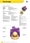
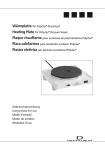
IN
Paratherm
Vermessungs- und thermisches Ausblockgerät
Surveying, blocking-out and waxing unit
Parallèlometre avec dispositif thermique incorporé
Paralelómetro con dispositivo térmico
REF 094-270-00
Gebrauchsanweisung
Instructions for use
Mode d’emploi
Modo de empleo
DE
1
DE
Konformitätserklärung
1.1 Allgemeiner Hinweis
Danke, dass Sie sich für ein Dentaurum-Gerät entschieden haben. Damit Sie lange Freude mit Ihrem neuen
Paratherm haben, beachten Sie bitte alle Hinweise in dieser Gebrauchsanweisung.
EG-Konformitätserklärung
Sicherheitshinweise
Hiermit erklären wir,
! Vorsicht
Dentaurum GmbH & Co. KG
Turnstraße 31
75228 Ispringen
2.1 Entsorgung
dass das nachfolgend bezeichnete Laborgerät aufgrund seiner Konzipierung und Bauart sowie in der von
uns in Verkehr gebrachten Ausführung den einschlägigen grundlegenden Sicherheits- und Gesundheitsanforderungen und den EG-Richtlinien entspricht. Bei einer nicht mit uns abgestimmten Änderung des
Gerätes verliert diese Erklärung ihre Gültigkeit.
Bezeichnung des Laborgerätes
Vermessungs- und thermisches Ausblock-Gerät
REF
094-270-00
Gerätetyp
Paratherm
Ab Gerätenummer
32-080
EG-Richtlinien
EG-Richtlinie Elektromagnetische Verträglichkeit
(89/336/EWG; i.d.F. 92/031/EWG
Änderungsrichtlinie für o. g. RL
(93/068/EWG)
Angewandte
harmonisierte Normen
Datum/Hersteller-Unterschrift
Angaben zum Unterzeichner
Bei der endgültigen Außerbetriebnahme des Dentaurum-Gerätes sind die entsprechenden landesspezifischen Vorschriften einzuhalten. Fragen zur sachgerechten Entsorgung des Dentaurum-Gerätes
beantwortet Dentaurum oder der dentale Fachhandel.
Hinweis:
Dieses Symbol zeigt an, dass das damit gekennzeichnete Produkt nicht als normaler Haushaltsabfall
entsorgt werden soll. Der Gesetzgeber verwehrt gewerblichen Kunden die Rückgabe von Altgeräten über kommunale Sammelstellen. Nähere Informationen erhalten Sie von Dentaurum oder
dem dentalen Fachhandel.
1 Parathermgerät mit Vermessungs- und thermischem Ausblockarm
1 Sucherstab
A
1 Minenhalter
B
10 Ersatzminen
C
4 Unterschnittmesser 0,25 / 0,35 / 0,50 / 0,75 mm D
2 Thermische Ausblockspitzen 0°, 2°
E
1 Haube
EN 55011
EN 50082
EN 61010
14.07.2005
Lesen Sie die Gebrauchsanweisung vor der Installation und der Inbetriebnahme
des Gerätes aufmerksam durch. Schalten Sie erst danach das Gerät ein!
2.2 Lieferumfang
EG-Richtlinie Elektrische Betriebsmittel zur Verwendung innerhalb
bestimmter Spannungsgrenzen
(73/023/EWG)
2
2
1 Sicherung T 0,25 A
1 Gebrauchsanweisung mit Konformitätserklärung
..........................................................
- i. V. Dipl.-Ing.(FH) K.Merkle Fertigungsleiter Gerätebau
3
Einsatzbereich
Modellguss, Kombinationstechnik, Konuskronen, Montage von Ankern und Geschieben.
3
DE
4
DE
Installation
6
Ersatzteile
0°
2°
REF 094-275-00
REF 094-277-00
E
E
0,25 mm
0,35 mm
0,50 mm
0,75 mm
REF 094-283-00
REF 094-284-00
REF 094-285-00
REF 094-286-00
D
D
D
D
1 Sucherstab
REF 094-287-00
A
1 Minenhalter
REF 094-288-00
B
10 Ersatzminen
REF 094-289-00
C
Benötigte Spannung an der Gerätebodenseite einstellen (110 / 220 / 240 V). Erst danach Gerät ans Netz
anschließen. Paratherm auf eine ebene Arbeitsfläche stellen.
1 Thermische Ausblockspitze
1 Thermische Ausblockspitze
5
1
1
1
1
Bedienung des Paratherm
Meistermodell in vorhandenen oder mitgelieferten Modelltisch einspannen. Rändelschraube ! öffnen und
Gleitstangen in die benötigte Höhe schieben. Mit Feststellring " fixieren. Werkzeug, z. B. Sucherstab, in den
Vermessungsgriff # einspannen und thermische Ausblockspitzen nach Wahl in den thermischen Ausblockgriff $ einschieben.
Modelltisch % in eine beliebige Position auf der
Arbeitsplatte & bringen. Feststellschrauben ' lösen,
so dass die Arme sich frei bewegen. Thermische Ausblockung ( einschalten und gewünschte Wärme
(max. 160 °C) am Regler ) wählen.
Achtung! Wechsel der Ausblockspitzen * nur im angewärmten Zustand.
5.1 Elektrisches Wachsmesser
Kabelanschluss über Steckbuchse an der Geräterückseite. Wachsmesser nur mit aufgestecktem
Messer betreiben.
7
Unterschnittmesser
Unterschnittmesser
Unterschnittmesser
Unterschnittmesser
Empfehlenswertes Zubehör
(Nicht im Lieferumfang von REF 094-270-00 enthalten)
1
1
1
1
1
Thermische Ausblockspitze 1°
Thermische Ausblockspitze 3°
Thermische Ausblockspitze 4°
Thermische Ausblockspitze 6°
Thermische Ausblockspitze 8°
REF 094-276-00
REF 094-278-00
REF 094-279-00
REF 094-280-00
REF 094-281-00
Modelltisch
REF 086-340-00
Elektrisches Wachsmesser
Handstück, Kabel und 1 Wachsmesser,
Halter für Handstück
Trafo und Potentiometer zur Regelung
der Wärme sind bereits im Paratherm
(REF 094-270-00) eingebaut
REF 094-272-00
Wachsmesser, klein
REF 089-602-00
Modellierspitze
nach Thomas, klein
REF 089-603-00
Modellierspitze
nach Thomas, mittel
REF 089-604-00
KFO-Wachsmesser
REF 089-605-00
Modellierlöffel
REF 089-606-00
E
E
E
E
E
Gewünschte Temperatur am Potentiometer +
einstellen. Maximale Temperatur 280 °C.
Achtung! Wachsmesser nur im warmen Zustand
wechseln.
5.2 Feststellung des Vermessungsarmes
Vermessungsgriff # nach vorne zur Mitte der Arbeitsplatte schwenken und mit den Schrauben ! ' fixieren.
Am Vermessungsarm Hilfsteil einspannen und Höhe an ' fixieren. Modelltisch mit eingespanntem Modell
an das Hilfsteil heranführen. Höhe korrigieren.
Bei Ersatzteilbestellungen bitte Gerätenummer (Typenschild Geräterückseite) angeben.
4
5
EN
1
EN
Declaration of conformity
1.1 General information
Thank you for having chosen a Dentaurum unit. Please study these instructions for use carefully so that you
may enjoy the benefits of using this Paratherm unit.
EEC-Declaration of conformity
Dentaurum GmbH & Co. KG
Turnstraße 31
D 75228 Ispringen
hereby declares that the design and construction of the laboratory equipment described below, including
the version marketed by us, comply with the basic regulations governing safety and health as stated in the
EEC guidelines. This declaration will become invalid if the laboratory equipment is modified or altered in
any way without our prior consent.
Description of the unit
Surveying, blocking-out and waxing unit
REF
094-270-00
Type
Paratherm
Start with unit No.
32-080
EEC guidelines
92/031/EEC
89/336/EEC
Electromagnetic compatibility
Modified guideline
73/023/EEC
93/068/EEC
Applied unified standards
Date/manufacturer‘s signature
Signatory
2
Safety instructions
! Caution
Read through the instructions for installing and operating the unit carefully before
switching it on.
2.1 Disposal
When a Dentaurum product is finally no longer in use the disposal regulations of that particular country
apply. Dentaurum or the dental trade is available to answer questions regarding the correct disposal of any
specific product.
Note:
This symbol indicates, products marked with it should not be disposed off together with garbage
of households. The legislator disallows commercial customers to return electronic waste via municipial collection points. Further information is available through Dentaurum or the dental trade.
2.2 Delivery
1 Paratherm unit with surveying / blocking-out arm
Electrical equipment used within certain
voltage limits
1 Analyzing rod
A
Modifications of the above guidelines
1 Graphite holder
B
10 Replacement graphite markers
EN 55011
EN 50082
EN 61010
14.07.2005
C
4 Undercut gauges 0.25 / 0.35 / 0.50 / 0.75 mm D
2 Thermal blocking-out instruments 0°, 2°
..........................................................
- p. p. Dipl.-Ing.(FH) K.Merkle Production Manager Mechanic
E
1 Plastic cover
1 Fuse T 0.25 A
1 Instructions for use with EEC-Declaration of conformity
3
Areas of use
Cast partial denture, combination techniques, conical crowns, positioning of snap attachments and
attachments.
6
7
EN
4
EN
Installation
6
Spare parts
Set the necessary voltage on the underside of the unit (110 / 220 / 240 V). Then connect the unit to the
mains supply. Stand the Paratherm on a level working area.
1 Thermal blocking-out instrument 0°
1 Thermal blocking-out instrument 2°
REF 094-275-00
REF 094-277-00
E
E
5
1
1
1
1
REF 094-283-00
REF 094-284-00
REF 094-285-00
REF 094-286-00
D
D
D
D
1 Analyzing rod
REF 094-287-00
A
1 Graphite holder
REF 094-288-00
B
REF 094-289-00
C
Operating the Paratherm
Mount the master model on the model table already available or supplied with the unit. Loosen the knurled
screw ! and raise the sliding rods to the necessary level. Fasten with retainer ring ". Grip the instrument
eg. analyzing rod in the surveying handpiece # and
push the selected blocking-out instrument into the
thermal blocking-out handpiece $.
Place the model table % in the most convenient
position on the work surface &. Loosen the locking
screws ', so that the arms may be moved freely.
Switch on the thermal blocking-out handpiece ( and
set the desired temperature (maximum 160 °C /
320 °F) on the controller ).
Caution! Only change the blocking-out instruments
* whilst they are still warm.
Undercut gauge
Undercut gauge
Undercut gauge
Undercut gauge
0.25 mm
0.35 mm
0.50 mm
0.75 mm
10 Replacement graphite markers
7
Recommended accessories
(Not included in original kit REF 094-270-00)
1
1
1
1
1
Thermal blocking-out instrument
Thermal blocking-out instrument
Thermal blocking-out instrument
Thermal blocking-out instrument
Thermal blocking-out instrument
1°
3°
4°
6°
8°
REF 094-276-00
REF 094-278-00
REF 094-279-00
REF 094-280-00
REF 094-281-00
E
E
E
E
E
5.1 Electric wax knife
The knife is connected by means of the socket on the
rear side of the unit. Only operate the wax-knife with
an instrument in the place.
Model table
REF 086-340-00
Electric wax knife
REF 094-272-00
Set the desired temperature on the potentiometer +.
Maximum temperature 280 °C / 536 °F.
Caution! Only change the knife whilst it is still warm.
5.2 Locking the surveying arm
(Positioning attachments)
Rotate the surveying handpiece # forwards of the centre of the work surface and lock into the position with
screws ! '.
Grip the wire aid in the surveying arm and fix the level using '. With the model already clamped into
position, guide the model table onto the wire aid. Correct the level.
When ordering spare parts please quote the unit number (type plate or rear side of the unit).
8
Handpiece, cable and 1 wax knife,
holder for handpiece
In order to regulate the temperature a
transformer and potentiometer have been
built into the Paratherm (REF 094-270-00)
Modelling knife, small
REF 089-602-00
Thomas modelling point,
fine
REF 089-603-00
Thomas modelling point,
medium
REF 089-604-00
Orthodontic wax knife
REF 089-605-00
Modelling spatula
REF 089-606-00
9
FR
1
FR
Déclaration de conformité
1.1 Informations générales
Nous vous remercions d’avoir choisi un appareil de Dentaurum. Afin de profiter longtemps et pleinement
de votre nouvel appareil, nous vous conseillons de respecter toutes les recommandations du présent mode
d’emploi.
2
Déclaration de conformité CE
Par le présent document, nous,
Consignes de sécurité
attentivement le mode d’emploi avant l’installation et la mise en service de
! Attention lisez
l’appareil. N’allumer qu’ensuite l’appareil !
Dentaurum GmbH & Co. KG
Turnstraße 31
75228 Ispringen – RFA
2.1 Elimination
déclarons que l’appareil de laboratoire décrit ci-après répond, tant par sa conception, que dans sa
réalisation, notamment en ce qui concerne le modèle commercialisé par nos soins, aux exigences
fondamentales des directives CE, en matière de sécurité et de santé. En cas de modification de cet
appareil de laboratoire, exécutée sans notre consentement, ce certificat serait automatiquement caduc.
Quand un produit Dentaurum est mis hors service de façon définitive, il convient de respecter les prescriptions d’élimination du pays pour ce produit. Pour toute question concernant une élimination appropriée
d’un produit Dentaurum, veuillez vous adresser à Dentaurum ou auprès d’un commerce spécialisé en
produits dentaires.
Désignation de l’appareil
Parallélomètre avec dispositif thermique incorporé
Note :
REF
094-270-00
Type de l‘appareil
Paratherm
A partir du n° de série
32-080
Directives CE
sur la compatibilité électromagnétique
modifiée par 92/031/CEE
Lorsque ce symbole figure sur un appareil électrique et électronique, cela signifie qu’il ne doit
pas être éliminé en tant que déchet ménager à la fin de son cycle de vie. Vous obtiendrez des
informations plus précises concernant ce sujet auprès de Dentaurum ou auprès d’un commerce
spécialisé en produits dentaires.
89/336/CEE
1 Appareil Paratherm avec bras de parallélisation
employé dans ceratines limites de tension 73/023/CEE
sur le matériel électrique destiné à être
Normes
harmonisées appliquées
Date / signature du fabricant
Identité du signataire
93/068/CEE
1 Bras de recherche
A
1 Porte-mine
B
10 Mines de rechange
EN 55011
EN 50082
EN 61010
14.07.2005
2.2 Contenu de la livraison
..........................................................
- Dipl.-Ing.(FH) K.Merkle Chef de Mécanique
C
4 Jauges 0,25 / 0,35 / 0,50 / 0,75 mm
D
2 Pointes thermiques de parallélisation 0°, 2°
E
1 Capot
1 Fusible T 0,25 A
1 Mode d‘emploi avec déclaration de conformité CE
3
Champs d’utilisation
Coulée sur modèle, technique multi-fonctions, couronnes coniques, montage de crochets et positionneurs
d‘ancrages.
10
11
FR
4
FR
Installation
6
Pièces de rechange
Régler la tension appropriée sur le fond de l‘appareil (110 / 220 / 240 V) avant de brancher l‘appareil sur le
secteur. Placer l‘appareil Paratherm sur une surface plane.
1 Pointe thermique de parallélisation 0°
1 Pointe thermique de parallélisation 2°
REF 094-275-00
REF 094-277-00
E
E
5
1
1
1
1
REF 094-283-00
REF 094-284-00
REF 094-285-00
REF 094-286-00
D
D
D
D
1 Bras de recherche
REF 094-287-00
A
1 Porte-mine
REF 094-288-00
B
REF 094-289-00
C
REF 094-276-00
REF 094-278-00
REF 094-279-00
REF 094-280-00
REF 094-281-00
E
E
E
E
E
Utilisation de l‘appareil Paratherm
Bloquer le modèle primaire sur le porte-modèle existant ou qui a été fourni. Dévisser la vis moletée ! et
placer les barres coulissantes à la hauteur nécessaire. Bloquer avec la bague de blocage ". Fixer l‘outil, par
exemple le bras de recherche, dans la poignée de
mesure # et introduire les pointes thermiques de
parallélisation au choix dans la poignée thermique de
parallélisation $.
Placer le porte-modèle % dans une position
quelconque sur la surface de travail &. Desserrer les
vis de blocage ', de manière à ce que les bras
puissent bouger librement. Mettre l‘appareil de
parallélisation ( en route et sélectionner la chaleur
souhaitée (max. 160 °C) sur le régulateur ).
Attention ! Ne changer les pointes de parallélisation
* qu‘à chaud (préchauffage).
Jauge
Jauge
Jauge
Jauge
0,25 mm
0,35 mm
0,50 mm
0,75 mm
10 Mines de rechange
7
Accessoires en option
(Non fournis en REF 094-270-00)
1
1
1
1
1
Pointe thermique de parallélisation 1°
Pointe thermique de parallélisation 3°
Pointe thermique de parallélisation 4°
Pointe thermique de parallélisation 6°
Pointe thermique de parallélisation 8°
5.1 Couteau à cire électrique
Brancher le câble sur le connecteur se trouvant à la
partie arrière de l‘appareil. N‘utiliser le couteau à cire
que lorsque la lame est en place.
Porte-modèle
REF 086-340-00
Couteau à cire électrique
REF 094-272-00
Régler la température souhaitée au moyen du
potentiomètre +. Température maximale 280 °C.
Attention ! Ne changer le couteau à cire qu‘à chaud.
5.2 Fixation du bras de mesure
(Montage de positionneurs d‘ancrage)
Faire pivoter la poignée de mesure # vers l‘avant au centre du plateau de travail et le fixer avec les vis ! et '.
Placer la pièce auxiliaire sur le bras de mesure et régler la hauteur sur '. Amener le porte-modèle avec le
modèle qui y est fixé vers la pièce auxiliaire. Corriger la hauteur.
En cas de commande des pièces détachées. Veuillez indiquer le numéro de l‘appareil (indiqué sur la plaque
signalétique au dos de l‘appareil).
12
Pièce à main, câble et 1 couteau à cire,
support pour pièce à main
Le transformateur et le potentiomètre pour
le réglage de la chaleur sont déjà intégrés
dans le Paratherm (REF 094-270-00)
Couteau à cire, petit
REF 089-602-00
Pointe de modelage
selon Thomas, fine
REF 089-603-00
Pointe de modelage
selon Thomas, moyenne
REF 089-604-00
Couteau à cire pour l‘orthodontie
REF 089-605-00
Spatule
REF 089-606-00
13
ES
1
ES
Declaración de conformidad
1.1 Indicación general
Gracias por haberse decidido por un aparato de Dentaurum. Para que pueda aprovechar al máximo y por
mucho tiempo su nuevo aparato Paratherm, tenga en cuenta todas las indicaciones de este modo de empleo.
Declaración de conformidad CE
2
Indicaciones de seguridad
Por la presente,
! Precaución
Dentaurum GmbH & Co. KG
Turnstraße 31
75228 Ispringen
2.1 Eliminación de desechos
declara que el equipo de laboratorio indicado a continuación corresponde en cuanto a su concepción y
construcción, asi como en la versión puesta en el mercado por nuestra empresa, a los requisitos básicos
aplicables de seguridad y sanidad de las Directivas CE. La presente declaración pierde su validez en caso
de modificaciones del equipo de laboratorio que se realicen sin nuestra autorización.
Denominación del aparato
Paralelómetro con dispositivo térmico
REF
094-270-00
Tipo del aparato
Paratherm
Nota:
2.2 Suministro
Compatibilidad electromagnética
en el c. 92/031/CEE
Utillajes eléctricos para el uso dentro
de determinados limites de tensión
89/336/CEE
73/023/CEE
1 Aparato Paratherm con brazo de medición y de desmontaje
1 Barra detectora
A
1 Portaminas
B
10 Minas de repuesto
Modificación de las Directivas citadas 93/068/CEE
Normas
armonizadas aplicadas
Al poner definitivamente fuera de servicio el producto de Dentaurum hay que atenerse a las correspondientes disposiciones específicas del pais en cuestión. Dentaurum o del comercio dental responde a las
preguntas relacionadas con la pertinente eliminación de desechos de productos de Dentaurum.
Los aparatos eléctricos y electrónicos marcados con este símbolo no deben desecharse junto con los
residuos domésticos de cualquier índole al final de su vida útil. La legislación actual no permite a los
usuarios comerciales depositar basura electrónica en los puntos de recogida establecidos por los
municipios. Más informaciones al respecto recibe usted de Dentaurum o del comercio dental.
A partir del número de aparato 32-080
Directivas CE
Lea atentamente las instrucciones de empleo antes de instalar y poner en servicio
el aparato. ¡No conecte el aparato antes de haber realizado este paso!
C
4 Rosetas de medición 0,25 / 0,35 / 0,50 / 0,75 mm D
EN 55011
EN 50082
EN 61010
2 Puntas térmicas 0°, 2°
E
1 Cubierta protectora
1 Fusible de red T 0,25 A
Fecha / Fabricante – Firma
Información sobre el firmante
14.07.2005
..........................................................
- p. d. Dipl.-Ing.(FH) K.Merkle Jefe de Mecánica
1 Modo de empleo con declaración de conformidad CE
3
Aplicación
Esqueléticos, técnica combinada, coronas cónicas, montaje de anclajes y attaches.
14
15
ES
4
ES
Instalación
6
Piezas de repuesto
0°
2°
REF 094-275-00
REF 094-277-00
E
E
0,25 mm
0,35 mm
0,50 mm
0,75 mm
REF 094-283-00
REF 094-284-00
REF 094-285-00
REF 094-286-00
D
D
D
D
1 Barra detectora
REF 094-287-00
A
1 Portaminas
REF 094-288-00
B
REF 094-289-00
C
Regular la tensión necesaria en el fondo del aparato (110 / 220 / 240 V). Tan sólo después de ello se
conectará el aparato a la red. Colocar el Paratherm sobre una superficie de trabajo plana.
1 Punta térmica
1 Punta térmica
5
1
1
1
1
Manejo del Paratherm
Sujetar el modelo principal en el portamodelos disponible o suministrada. Abrir el tornillo moleteado !
y correr las varillas de deslizamiento hasta la altura necesaria. Inmovilizarlas mediante el anillo de fijación ".
Sujetar el utensilio, p. ej. la barra detectora, en la
empuñadura de medición # e introducir la punta
térmica elegida en la empuñadura de desmontaje $.
Colocar el portamodelos % en la posición deseada
sobre la plancha de trabajo &. Aflojar los tornillos de
fijación ' de modo que los brazos se puedan mover
libremente. Conectar el dispositivo de desmontaje
térmico (, eligiendo el calor deseado (máx. 160 °C)
mediante, el regulador ).
¡Atención! Cambiar las puntas térmicas * sólo en
estado caliente.
Roseta de medición
Roseta de medición
Roseta de medición
Roseta de medición
10 Minas de repuesto
7
Accesorios recomendados
(No incluidas en el suministro de REF 094-270-00)
1
1
1
1
1
Punta térmica 1°
Punta térmica 3°
Punta térmica 4°
Punta térmica 6°
Punta térmica 8°
REF 094-276-00
REF 094-278-00
REF 094-279-00
REF 094-280-00
REF 094-281-00
E
E
E
E
E
5.1 Espátula eléctrica
Conexión por cable que se enchufa en el conector
situado en el lado posterior del aparato. Tenerla en
funcionamiento sólo con la espátula puesta.
Portamodelos
REF 086-340-00
Espátula eléctrica
REF 094-272-00
Graduar la temperatura deseada mediante el
potenciómetro +. Temperatura máxima 280 °C.
¡Atención! Cambiar la espátula sólo en estado caliente.
5.2 Fijación del brazo de medición
(Montaje de attaches)
Girar la empuñadura de medición # hacia adelante, llevándola al centro de la plancha de trabajo, e inmovilizarla
mediante los tornillos ! '.
Sujetar la pieza auxiliar en el brazo de medición y fijar la altura en '. Acercar la mesa portamodelos, con el
modelo fijo en la misma, a la pieza auxiliar. Corregir la altura.
En caso de pedidos de piezas de repuesto, favor de mencionar el número del aparato (indicado en la placa
de identificación en el fondo del aparato).
16
Pieza de mano, cable y 1 espátula,
soporte para pieza de mano
El transformador y el potenciómetro para
regular el calor ya vienen incorporados
en el Paratherm (REF 094-270-00)
Espátula, pequeña
REF 089-602-00
Punta de modelar
seg. Thomas, fina
REF 089-603-00
Punta de modelar
seg. Thomas, mediana
REF 089-604-00
Espátula de cera p.
ortopedia maxilar
REF 089-605-00
Cucharilla de modelar
REF 089-606-00
17
Notes
18
19
Für Ihre Fragen zur Verarbeitung unserer Produkte steht Ihnen unser Customer Support
gerne zur Verfügung.
Hotline Tel.-Nr. Zahntechnik
+ 49 72 31 / 803 - 410
Telefonische Auftragsannahme
+ 49 72 31 / 803 - 210
Mehr Informationen zu Dentaurum-Produkten finden Sie im Internet.
www.dentaurum.com
Date of information:
Mise à jour :
Fecha de la información:
989-909-00
Printed by Dentaurum
Germany
08/115
08/15/B/R1-7
Stand der Information:
Turnstr. 31 I 75228 Ispringen I Germany I Tel. + 49 72 31 / 803 - 0 I Fax + 49 72 31 / 803 - 295
www.dentaurum.com I [email protected]