1
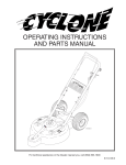
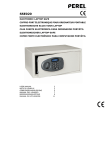
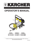
WATER JET
SYSTEM
OPERATOR’S MANUAL
PARKING LOT
AND DRIVEWAY
CLEANING
MADE EASY
For technical assistance or the dealer nearest you consult our web page at www.landa.com
8.913-945.0
3
CONTENTS
Introduction..................................................................................................................................... 4
Important Safety Information.......................................................................................................... 4
General Operating Techniques.................................................................................................... 4-5
High Pressure Swivel Information................................................................................................... 5
Exploded View................................................................................................................................ 6
Parts List, Exploded View............................................................................................................... 7
Troubleshooting.............................................................................................................................. 8
Nozzle Chart................................................................................................................................... 8
Warranty......................................................................................................................................... 9
Spanish Translations............................................................................................................... 10-11
Model Number ______________________________
Serial Number ______________________________
Date of Purchase ____________________________
The model and serial numbers will be found on a decal attached
to the pressure washer. You should record both serial number and
date of purchase and keep in a safe place for future reference.
WATER JET SYSTEM Manual • Form #8.913-945.0 • Revised 9/11
4
WATER JET SYSTEM
INTRODUCTION
The Water Jet is designed to attach to a pressure washer
which causes rotation of two high pressure nozzles
which will contain the spray as well as determine the size
of the swath when cleaning surfaces such as parking
lots, driveways and sidewalks.
It also has an attached spray gun and hose for isolated
cleaning areas. The height adjustment knob allows for
cleaning variations by easily raising or lowering the
rotating pressure spray.
Owner/User Responsibility:
The owner and/or user must have an understanding of
the manufacturer’s operating instructions and warnings
before using this Water Jet. Warning information should
be emphasized and understood. If the operator is not
fluent in English, the manufacturer’s instructions and
warnings shall be read to and discussed with the operator in the operator’s native language by the purchaser/
owner, making sure that the operator comprehends its
contents.
Owner and/or user must study and maintain for future
reference the manufacturers’ instructions.
This manual should be considered a permanent
part of the machine and should remain with it if
machine is resold.
When ordering parts, please specify model and
serial number.
IMPORTANT SAFETY
INFORMATION
WARNING
CAUTION
READ OPERATOR’S
MANUAL
THOROUGHLY
PRIOR TO USE
WARNING
HIGH PRESSURE
STREAM CAN
PIERCE SKIN
AND TISSUE
CAUTION: To reduce the risk of
injury, read operating instructions
carefully before using.
1. Read the owner’s manual thoroughly. Failure to follow instructions could cause malfunction
of the machine and result in
death, serious bodily injury
and/or property damage.
WARNING: High pressure stream
of fluid that this equipment can
produce can pierce skin and its
underlying tissues, leading to serious injury.
2. High pressure developed by
these machines will cause
personal injury or equipment
damage. Use caution when operating. Do not direct discharge
INSTRUCTION MANUAL AND PARTS LIST
stream at people or animals or severe injury or death
will result.
3. Never make adjustments on machine while it is in
operation.
4. Eye safety devices and foot protection must be worn
when using this equipment.
5. The best insurance against an accident is precaution
and knowledge of the machine.
6. Never point the Water Jet wand at any part of your
body or at anyone standing within 10 feet as serious
injury could occur.
WARNING
USE PROTECTIVE
CLOTHING WHEN
OPERATING.
WARNING: High pressure spray can
cause paint chips or other particles
to become airborne and fly at high
speeds.
7. Safety clothing and protective
eyecovering must be worn.
8. Water Jet assembly comes
equipped with a #6 nozzle in the
spray gun and two #3 nozzles
in the rotating swivel. Check your machine nozzle
size before using.
9. We will not be liable for any alterations made to
our standard machines, or the application of any
components not purchased from us.
10. Pressure must NOT exceed 4,000 PSI. Temperature must NOT exceed 200°F. Flow rate must NOT
exceed 6 GPM.
11. To protect from freezing, squeeze trigger on spray
gun and lower the hose to allow water to drain. Flow
rate must NOT exceed 6 GPM.
GENERAL OPERATING
TECHNIQUES
1. Disconnect pressure washer spray gun from high
pressure hose. These items are not included, but
are provided with the soon to be attached pressure
washer.
2. Attach the female nipple, supplied with the Water
Jet, to the pressure washer high pressure hose.
NOTE: We recommend using no mar hose to
prevent black marks from appearing on the
cleaning surface.
3. Couple the pressure washer high pressure hose to
the Water Jet.
4. Inspect your pressure washer nozzle size. The Water
Jet surface cleaner comes with two #3 nozzles. If
your pressure washer requires a nozzle larger than
a #6, consult with your local dealer.
WATER JET SYSTEM Manual • #8.913-945.0 • Rev. 9/11
WATER JET SYSTEM
INSTRUCTION MANUAL AND PARTS LIST
NOTE: For ideal cleaning, the Water Jet must be
attached to a minimum 4 gpm at 3,000 psi pressure washer.
5. Adjust the rotary spraybar to its highest position.
Loosen the adjustment knob (item #7) on the front
of the Water Jet dome and slide the knob upward to
raise the rotary spraybar to its highest position and
tighten.
6. Turn on water supply and start pressure washer.
NOTE: It is always important to test in a small
area for the correct height adjustment needed
so surface being cleaned won’t be damaged.
7. Pull the trigger for water to start cleaning surface.
NOTE: Never stop moving the Water Jet while
trigger is engaged and surface is being sprayed
or damage to surface could occur.
8. For use of the spray gun in isolated cleaning, check
the nozzle size (item 24). The Water Jet is shipped
with a #6 nozzle; if your pressure washer requires a
larger nozzle, you will need to use the nozzle from
your pressure washer.
NOTE: For use of the spray gun, be aware that
the Water Jet comes with a #6 nozzle and two #3
nozzles on the rotary swivel.
HIGH PRESSURE
SWIVEL INFORMATION
The Water Jet high pressure swivel will “weep” water
from underneath the dome cover (item 1). This weeping
is normal for this swivel and will weep even more with hot
water than with cold. The swivel uses water to lubricate
its floating seal face to keep wear down to a minimum.
Also the high pressure swivel is equipped with a grease
fitting and should be greased at least once every three
months. A good quality ball bearing grease is recommended. DO NOT OVER GREASE THE BEARING!
The Warranty for this high pressure swivel is one year
from date of purchase.
WATER JET SYSTEM Manual • #8.913-945.0 • Rev. 9/11
5
WATER JET SYSTEM
6
INSTRUCTION MANUAL AND PARTS LIST
EXPLODED VIEW
1
2
48
62
30
3
29
4
2
27
60
47
7
6
15
5
28
25
23
31
48
61
57
26
11
9
24
22
20
33
59
54
35
34
10
21
39
42
56
43
46
44 49
63
51
58
58
18
▲
60
16
55
38
32
37
8
50
20
36
51
52
13
12
45
41
19
40
8
60
59
60
59
53
9
14
17
WATER JET SYSTEM Manual • #8.913-945.0 • Rev. 9/11
42
8
WATER JET SYSTEM
INSTRUCTION MANUAL AND PARTS LIST
7
EXPLODED VIEW
PARTS LIST
ITEM PART NO.
DESCRIPTION
QTY
ITEM PART NO.
DESCRIPTION
1 8.706-579.0
Dome, Water Jet, Height Adjustment
1
2
8.706-207.0
Elbow, Street, 3/8"
2
3
8.719-964.0
Clamp, Rotary Swivel,
4
8.707-011.0
36
8.706-163.0
Elbow, Male, 1/4" Pipe
1
37
8.719-966.0
Adapter, Valve, Trigger Bar
1
38
8.719-101.0
Hook, #10/24" x 2" NC
1
1
8.718-857.0
▲ Nut, 10/24", Hex, Whiz Loc 1
Swivel, Rotary Union
1
8.719-019.0
▲ Washer, Split, Lock
1
8.941-711.0
Washer, Brass
1
39
8.706-233.0
Tee, Street, 1/4", Steel
1
5
8.719-962.0
Shaft, Extension, Water Jet
1
40
8.718-244.0
Valve, Actuator, Assy.
1
6
8.719-963.0
Block, Slide Adjustment
1
7
8.719-063.0
Knob, 3/8" x 1", Water Jet
1
81-21227
▲ Kit, Repair, 200 Series (for 81-21007L)
1
8
9.802-782.0
Collar, 5/8" Bore Shaft
6
41
8.719-069.0
Pin, Roll m2.5 x 24 mm
1
9 4-0303
Wheel & Tire Assy. 4"
Tubeless
42
8.706-200.0
Elbow, Street, 1/4"
2
2
43
8.707-012.0
Swivel, High Pressure, 1/4"
1
10
8.706-580.0
Bearing, 1" Roller, Dbl Seal
1
44
8.706-301.0
Adapter, 3/8" x 1/4"
1
11
8.719-961.0
Base, Slide Adjustment
1
12
8.711-908.0
Wheel, Castor 3" Grey
1
45 9.802-170.0
Nipple, 3/8" x 3/8", NPT ST, Female
1
13
8.706-578.0
Base, Water Jet, Polyethylene 1
46
8.912-853.0
Plate, Backup, Splash Guard
1
14
8.725-311.0
Spray Arm Assy, Complete, SS1
47
8.706-297.0
Bushing, 3/8" x 1/4", Steel
1
15 9.802-813.0
Washer, 5/16", Lock, Split,
Ring
48
8.718-724.0
Screw, 3/8" x 2" Sockethead
4
1
49
9.802-169.0
Coupler, 3/8" Male
1
16 9.802-696.0
Nut, 10/32", NF, ST, KEP
4
50
8.705-969.0
Nipple, 1/4" Close 1
17
8.711-370.0
Nozzle Only, SA,1/4", Meg-15032
51
8.900-222.0
Label, Water Jet Warning
2
18
8.707-387.0
Guard, Splash, Water Jet
1
52
8.709-113.0
Clamp
1
19
8.912-849.0
Axle, 5/8" x 18.5", Stainless
1
53
8.706-557.0
Bellows, Leg Boot
1
20
8.706-560.0
Cap, Black Vinyl, Water Jet
4
54
8.715-871.0
Bearing, Water Jet Boot Holder 1
21
8.912-851.0
Handle Assy., Lower
2
55
8.706-999.0
Connector, 1/4" Anchor
1
22
8.912-852.0
Handle, Water Jet, Upper Assy.1
56
8.718-727.0
Screw, 1/4" x 2"
4
23
8.718-710.0
Eyebolt, 3/8" x 4"
57
8.718-880.0
Nut, Wing 1/4"
4
24
8.712-364.0
Nozzle SAQCMEG 4006, White1
8.719-019.0
▲ Washer, Split Lock
4
25
8.711-311.0
Wand, Insulated, Water Jet
1
58
9.802-726.0
Bolt, 3/8" x 1-3/4" SS
5
26
9.802-164.0
Coupler, 1/4" Female
1
59
9.802-780.0
Nut, 3/8" SS ESNA
9
27
8.719-109.0
Bolt, 5/16" x 3", J-Bolt
1
60
9.802-808.0
Washer, 3/8" SS
10
28
9.802-787.0
Nut, 5/16", Cap
1
29 8.751-234.0
Gun, Landa, L1050,
5000 PSI, 10.4 GPM
61 8.718-723.0
Screw, 3/8" x 1-1/2"
Sockethead
2
1
62
9.802-759.0
Screw, 10/32" x 1/2"
3
30
8.719-965.0
Handle, Trigger Bar, Water Jet 1
9.804-082.0
▲ Washer, 1/4", SAE, Black
3
31
8.918-185.0
Hose, 30" x 1/4", Pres Bypass 1
63
8.718-653.0
Screw, 10/32" x 1/2", SHCS, SS4
1
32 8.718-951.0
Set Screw, 10/32" x 1/4" SS.
Socket Head
1
33
8.918-187.0
Hose, 42" x 1/4" x 100R2 1
34
8.900-221.0
Label, Water Jet
1
35 8.709-175.0
Filter, 1/4" 36387-1/4",
High Pressure
1
8.709-176.0
▲ Screen, High Pres.Filter S/S 1
2-990711
▲ Gasket, Nylon for 2-99071
1
WATER JET SYSTEM Manual • #8.913-945.0 • Rev. 9/11
▲ Not Shown
QTY
WATER JET SYSTEM
8
INSTRUCTION MANUAL AND PARTS LIST
TROUBLESHOOTING
PROBLEM
POSSIBLE CAUSE
SOLUTION
QUICK COUPLER LEAKS
Worn O-Ring
Replace O-Ring (Part #2-0121).
SPRAY GUN(S) LEAK
Foreign matter between valve seat
and ball
Remove foreign matter. Replace with
Repair Kit (Part #81-21227).
PRESSURE WASHER
UNLOADER CYCLES
High pressure filter or wrong sized
Remove and clean out filter, nozzle(s).
nozzles for attached pressure washer Check nozzle size.
NOZZLES SPINNING TOO
SLOW
Not enough water volume for
attached pressure washer to rotate
nozzles
Need a larger gpm pressure washer.
NOT CLEANING SURFACE
Height adjustment too high or
pressure washer too small for job
Lower adjustment knob or attach to
larger pressure washer.
ROTATING NOZZLE ARM NOT Pressure washer too small or
SPINNING, BEARING NOISE
bearing low on grease
Get larger gpm pressure washer or
grease bearing.
NOZZLE CHART
Correct nozzle size is important for optimum cleaning efficiency. Water Jet is shipped with two #3, 15° nozzles in rotary
swivel, and one #6, 40° nozzle in shut-off gun. Review correct nozzle size for your pressure washer. See chart below
for correct nozzle size. To obtain the correct nozzle size in the rotary swivel, divide the minimum nozzle size for the
pressure by two. Round this figure up to the nearest half nozzle size. These are the 1/8" nozzles only (two needed) for
the rotary swivel on the Water Jet.
Nozzle
Size
Orifice
diam.
(in.)
2
40
PSI
100
PSI
250
PSI
500
PSI
600
PSI
.034
.20
.32
.50
.71
.77
3
.042
.30
.47
700
PSI
800
PSI
1000
PSI
1200
PSI
1500
PSI
2000
PSI
2500
PSI
3000
PSI
3500
PSI
4000
PSI
.80
.89
1.0
1.1
1.2
1.4
1.6
1.7
1.9
2.0
.75 1.07 1.16
1.25
1.34
1.5
1.6
1.8
2.1
2.4
2.6
2.8
3.0
4
.052
.40
.63
1.00 1.40 1.60
1.70
1.80
2.0
2.2
2.5
2.8
3.1
3.5
3.8
4.0
4.5
.055
.45
.71
1.10 1.50 1.70
1.90
2.00
2.2
2.4
2.8
3.0
3.6
3.9
4.3
5.0
5
.057
.50
.79
1.30 1.80 1.90
2.10
2.20
2.5
2.8
3.1
3.6
4.0
4.4
4.7
5.0
5.5
.06
.55
.87
1.40 1.90 2.10
2.30
2.50
2.8
3
3.4
3.8
4.4
4.8
5.2
5.5
6
.062
.60
.95
1.50 2.10 2.30
2.50
2.70
3.0
3.2
3.7
4.2
4.8
5.2
5.7
6.0
6.5
.064
.65
1.00
1.70 2.30 2.50
2.70
2.90
3.3
3.6
4.0
4.6
5.2
5.7
6.0
7
.067
.70
1.10
1.80 2.50 2.70
2.90
3.10
3.5
3.8
4.3
5.0
5.6
7.5
.07
.75
1.20
1.90 2.70 2.90
3.20
3.40
3.8
4.1
4.6
5.3
6.0
8
.072
.80
1.30
2.00 2.80 3.10
3.40
3.60
4.0
4.4
5.0
5.6
8.5
.074
.85
1.30
2.20 3.00 3.30
3.60
3.80
4.3
4.6
5.3
6.0
9
.076
.90
1.40
2.30 3.20 3.50
3.80
4.00
4.5
5.0
5.5
9.5
.078
.95
1.50
2.40 3.40 3.70
4.00
4.30
4.8
532
5.8
10
.08
1.00
1.60
2.50 3.50 3.90
4.20
4.50
5.0
5.4
12
.087
1.20
1.90
3.00 4.20 4.60
5.00
5.40
6.0
15
.094
1.50
2.40
3.80 5.30 5.80
20
.109
2.00
3.20
5.00
30
.141
3.00
4.70
40
.156
4.00
WATER JET SYSTEM Manual • #8.913-945.0 • Rev. 9/11
WATER JET SYSTEM
OPERATOR’S MANUAL
Accessories And pArts WArrAntY
limited minimUm 90 dAY WArrAntY
We warrant to the original consumer that each new part and accessory sold by Landa will be free from manufacturing defects in materials or workmanship in normal service for the duration specified by the original component manufacturer with a
90 day minimum from date of purchase, provided it is installed properly and the equipment is maintained in accordance with
Landa’s instructions and manuals. Components manufactured by Landa, such as frames, handles, coil wraps, fuel tanks,
belt guards and heating coils have a one year warranty from date of purchase.
Our obligation under this warranty is expressly limited as to the replacement or repair, at our option, at Landa, Camas,
Washington 98607, or at a service facility designated by us, for such part or parts as inspection shall disclose to have been
defective.
exclUsions:
This warranty does not apply to defects caused by casualty or unreasonable use, including faulty repairs by others and
failure to provide reasonable and necessary maintenance.
limitAtion oF liABilitY
Landa’s liability for special, incidental, or consequential damages is expressly disclaimed. In no event shall Landa’s liability
exceed the purchase price of the product in question. Landa makes every effort to ensure that all illustrations and specifications are correct, however, these do not imply a warranty that the product is merchantable or fit for a particular purpose, or
that the product will actually conform to the illustrations and specifications. Our obligation under this warranty is expressly
limited at our option to the replacement or repair at a service facility or factory designated by us, of such part or parts as
inspection shall disclose to have neen defective. tHe WArrAntY contAined Herein is in lieU oF All otHer
WArrAnties, express or implied, inclUdinG AnY implied WArrAntY oF mercAntABilitY or Fitness
For A pArticUlAr pUrpose Are expresslY limited to tHe dUrAtion oF tHis Written WArrAntY. This
warranty gives you specific legal rights and you may also have other rights which vary from state to state.Landa does not
authorize any other party, including authorized Landa dealers, to make any representation or promise on behalf of Landa,
or to modify the terms, conditions, or limitations in any way. It is the buyer’s responsibility to ensure that the installation and
use of Landa products conforms to local codes. While Landa attempts to assure that its products meet national codes, it
cannot be responsible for how the customer chooses to use or install the product. some states do not allow limitations on
how long an implied warranty lasts or the exclusion or limitation of incidental or consequential damages, so the above limitation or exclusion may not apply to you.
to oBtAin WArrAntY service:
Purchaser must bring the accessory parts to an authorized Landa dealership. For the dealership nearest you consult our
web page: www.landa.com.
WATER JET SYSTEM Manual #8.913-945.0
Rev. 9/11
9
10
EQUIPO DE LAVADO A PRESIÓN
INTRODUCCION
El Sistema de Chorro de agua está diseñado para
adaptarse a una lavadora de presión haciendo rotar dos
boquillas de alta presión para producir el rociado y así
mismo determinar el tamaño del ancho de corte cuando
se limpian superficies de playas de estacionamiento,
pistas de acceso y veredas.
También tiene una pistola de presión con manguera para
limpieza de áreas aisladas. La perilla de regulación de
altura permite diferentes tipos de limpieza al aumentar
o disminuir la rotación de la presión de rociado.
Responsabilidad del Dueño/Usuario
El dueño/usuario debe entender las instrucciones de
operación y las advertencias del fabricante antes de
usar el Sistema de Chorro de agua. La información
de advertencia debe ser enfatizada y entendida. Si el
operador no habla inglés, las instrucciones y advertencias del fabricante deberán ser leídas y discutidas en
la lengua nativa del operador por el comprador/dueño,
asegurándose que el operador entienda su contenido.
El dueño y/o usuario deben estudiar y mantener las
instrucciones del fabricante para futuras referencias.
Este manual deberá ser considerado como una
parte de la máquina y debe permanecer así en
caso que se revenda la unidad.
Cuando ordene repuestos, por favor
especificar el modelo y el número de serie.
INSTRUCCIONES DE
SEGURIDAD IMPORTANTES
PRECAUCÍON: Para reducir el
riesgo de accidentes, leer cuidadosamente las instrucciones de
operación antes de usar la unidad.
1. Leer cuidadosamente el manual deldel operador. Elincumplimiento de las instruccio nes puede causar unoperación defectuosa
e inadecua- da de la unidad y puede provocar la muerte, causar heridas serias
y/o daños a la propiedad.
PRECAUCÍON
ADVERTENCIA
ADVERTENCIA: El flujo de líquido
de alta presión del equipo puede
producir perforaciones en los tejidos de la piel, causando heridas
graves.
2. La alta presión desarrollada
por estas unidades causará
accidentes personales o da
MANUAL DEL OPERADOR
ños al equipo. Sea precavido al operar. No descargar
el flujo directamente en personas o animales ya que
puede causar heridas graves o la muerte.
3. Nunca hacer ajustes a la máquina mientras esté
operando.
4. Deben usarse accesorios de seguridad para los ojos
y protección de los pies cuando se use este equipo.
5. El mejor seguro contra un accidente es la precaución
y el conocimiento de la máquina.
6. Nunca diriga la varilla del chorro de agua a cualquier
parte de su cuerpo o alguna persona a 10 pies de
distancia ya que podría producir heridas graves.
ADVERTENCIA: El chorro de alta presión puede
ADVERTENCIA ocasionar que trozos de pintura y
otras partículas vuelen por los aires
a altas velocidades.
7.Debe usarse ropa de seguridad
y protección para los ojos.
8.El ensamble del Sistema
de chorro de agua viene
equipado con una boquilla #6 en la pistola de
apagado y dos boquillas #3 en la placa giratoria.
Revise la boquilla de su equipo antes de usarlo.
9. No seremos responsable por cualquier cambio
hecho a nuestras unidades estándar o la aplicación
de cualquier otro componente no comprado de
nosotros.
10. La presión NO debe exceder 4,000 PSI. La
temperatura NO debe exceder 200°F.
11. Para protección contra congelamiento, apretar el
gatillo de la pistola en posición apagado y bajar la
manguera para drenar el agua.
TECNICAS GENERALES
DE OPERACION
1. Desconectar la pistola de alta presión de la
manguera de alta presión. Estos artículos no se
incluyen, pero serán provistos cuando se requieran
acoplar a la lavadora de presión.
2. Conectar la boquilla hembra, incluída con la
lavadora, a la manguera de agua de alta presión.
NOTA: Recomendamos no usar manguera tipo
mar para prevenir que aparezcan marcas negras
en la superficie que se está limpiando.
3. Acoplar la manguera de alta presión de la lavadora
al Sistema de chorro de agua
4. Inspeccionar el tamaño de la boquilla de la lavadora
de presión. El Sistema de chorro de agua viene con
dos boquillas #3. Si su lavador de presión requiere
una boquilla más grande que la #6, consulte con su
vendedor local.
WATER JET SYSTEM Manual • #8.913-945.0 • Rev. 9/11
EQUIPO DE LAVADO A PRESIÓN
NOTA: Para un lavado ideal, el Sistema de chorro
de agua debe adaptarse a un lavador de un
mínimo de 4 gpm y 3,000 psi de presión.
5. Regular la varilla de rociado en su posición más
alta. Aflojar la perilla de regulación (artículo #7) en
el domo frontal del equipo y deslizar la perilla hacia
arriba para elevar la varilla de rociado giratorio a su
posición más alta, luego ajustar.
6. Prender el suministro de agua y arrancar la lavadora
de presión.
NOTA: Siempre es importante probar en una área
pequeña para la correcta regulación de la altura
necesaria de tal manera que la superficie a ser
limpiada no sea dañada.
7. Tirar del gatillo para que el agua empiece a limpiar
la superficie.
NOTA: Nunca deje de mover el Sistema de chorro
de agua mientras el gatillo está accionado y la
superficie está siendo limpiada o podrían ocurrir
daños en la superficie.
8. Para usar la pistola en una sola limpieza, revisar el
tamaño de boquilla (artículo 24). El chorro de agua
es embalado con una boquilla #6; si su lavadora de
presión requiere una boquilla más grande, usted
necesitará usar la boquilla de la lavadora de presión.
NOTA: Para usar la pistola, tener presente que
el Sistema de chorro de agua viene con una
boquilla #6 y dos boquillas #3 sobre la placa
rotatoria.
MANUAL DEL OPERADOR 11
INFORMACION DEL
CABEZAL DE ALTA PRESION
El cabezal de alta presión del chorro de agua “derramará” agua por debajo de la cubierta de cúpula (artículo
1). Este derrame es normal para el cabezal y derramará
incluso más con el agua caliente que con la fría. El cabezal usa agua para lubricar su sello flotante y mantener
un desgaste mínimo.
El cabezal de alta presión también está equipado con un
accesorio para engrase y deberá ser engrasado por lo
menos una vez cada tres meses. Se recomienda una
grasa de buena calidad para cojinetes. NO SOBRECARGUE DE GRASA EL COJINETE!
La garantía para este cabezal de alta presión es de un
año desde la fecha de compra.
WATER JET SYSTEM Manual • #8.913-945.0 • Rev. 9/11
Form #8.913-945.0 • Revised 9/11 • Printed in U.S.A. by Landa