1
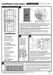
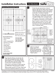
Door Hardware Installation Instructions - 2 Sided
WARNING: ALWAYS read & follow the operating & safety instructions in
the power tool owner's manual & the instructions for use of this accessory.
ALWAYS wear safety goggles & other appropriate safety items for protection.
NOTE: CHECK YOUR LOCKSET. This installation jig is for most common
locksets that specify a 2-3/8" or 2-3/4" backset (distance between the
door edge and center of the lockset)
For locksets other than 2-3/8" or 2-3/4" backset, do not use this
installation jig for boring the 2-1/8" large hole. Refer to the guide from
your lockset to locate the 2-1/8" large hole.
DOOR HINGE INSTALLATION
1. LOCATING THE DESIRED DOOR HINGE LOCATIONS.
If you are replacing a door and the hinge recesses exist on the door jam, there
are 2 methods of determining where to cut the recesses out on the door.
Method #1 - Measure the hinge locations of the previously used door from the
top of the door down (do not measure from the bottom up since this may
create a large gap at the top of the door).
Method #2 - Measure the distance from the top of the door jam down to the
first hinge and subtract 1/8". This will create a 1/8" clearance gap at the top
of the door.
If the door jam that you are installing the door into does not have hinges or hinge
recesses, mark the center of the hinge locations on the edge of the door. This
centering mark will be used in step 2 to locate the Hinge Template.
2. MAKING DOOR HINGE RECESS.
Screw Hinge Plate
Determine which way the door will
Template To Door
open and how the hinges will need
to be positioned for proper
operation. Locate the Hinge Template
on the edge of the
door such that the hole lines up with
the mark scribed in step one (the
Remove Material
center of the hinge).
Inside Template
Installation tip: With a pencil,
outline the inside of the Hinge
Figure A
Template, this is the area that will be
chiseled out. Remove the template and position the hinge inside the pencil lines to
verify the door will open as desired.
With the Hinge Template in place, insert a screw into the hole, and fasten the
template onto the door. With the template fastened to the door, use a chisel to
remove the material inside the template (Figure A). Remove the template and
chisel out material left behind at the template screw location. Screw the hinges
onto the door.
2. BORE FACE AND EDGE HOLES.
Attach 2-1/8" hole saw to pilot
bit/mandrel and affix to drill (Figure
C). Begin face bore through large
hole in jig at right angle to the door
face (Figure D). To avoid splintering,
STOP hole saw when pilot drill
appears on the other side of the
door. Remove saw and complete the
large bore from the other side of the
door. Next, replace 2-1/8" hole saw
with 1" hole saw. Using smaller hole
in template bore 1” hole through to
2-1/8” hole (Figure E).
3. MAKING RECESS FOR BOLT
PLATE. Remove the lockset latch
screws and template. Align the Bolt
Plate Template pins with the bolt
plate holes in the door and firmly
press the template into the holes
(Figure F).
Install the provided router bit into
drill. Drill the router bit into a guide
channel until the bushing shoulder
rests against the template
(Figure F). While holding the
bushing shoulder against the
template proceed to cut along the
guide channel. Do this for all
open channels.
After the guide channels have been
routed, remove the Bolt Plate
Template and chisel out the excess
material not removed by the router.
For a bolt plate with square corners,
carefully square off the corners with
a chisel.
Threaded Mandrel
and Hole Saw
Pilot Bit
Pilot Bit
2-Piece Mandrel
and Hole Saw
Figure C
Face Bore
2-1/8"
Hole Saw
Figure D
Edge Bore
1" Hole Saw
Figure E
4. INSTALL LOCKSET. Once the
recess for the bolt plate has been
created, follow the instructions for
the lockset installation.
Router Bit
Bolt Plate
Template
DOOR LOCKSET INSTALLATION
Figure F
1. SECURE TEMPLATE.
Set the Backset Guide to the
appropriate lockset backset. The
backset guide tabs indicate setting
of jig (Figure B). Position template
at desired latch height on door
edge. Secure the template to the
door by inserting 2 screws from
your lockset into the backset guide
(Figure B). These same holes will
be used in step 5 when installing
the lockset.
Set Backset Guide To
Appropriate Lockset Backset
2004
Secure Template
To Door
Figure B
G04871
Instrucciones de instalación de la cerradura – doble cara
ADVERTENCIA: SIEMPRE lea y siga las instrucciones de operación y
seguridad del manual del propietario de la herramienta motorizada y las
instrucciones para usar el accesorio.
SIEMPRE use gafas de seguridad y otros elementos de seguridad adecuados para
su protección.
NOTA: VERIFIQUE SU CERRADURA. Esta guía de instalación se usa para la
mayoría de las cerraduras que especifican una distancia entre el borde de
la puerta y el centro del pomo de la cerradura de 6,03 cm (2-3/8") o 6,99
cm (2-3/4")
Para cerraduras que tenga una distancia entre el borde de la puerta y el
centro del pomo de la cerradura diferente a 6,03 cm (2-3/8") o 6,99 cm
(2-3/4"), no utilice esta guía de instalación para perforar el hueco grande
de 5,40 cm (2-1/8"). Consulte la guía de su cerradura para localizar el
hueco grande de 5,40 cm (2-1/8").
INSTALACIÓN DE LAS BISAGRAS DE LA PUERTA
1. LOCALIZACIÓN DE LAS POSICIONES DESEADAS DE LAS
BISAGRAS DE LA PUERTA.
Si usted está reemplazando una puerta y las cavidades de las bisagras ya existen
en el marco de la puerta, hay 2 métodos para determinar dónde cortar las
cavidades de las bisagras en la puerta.
Método #1. Mida las posiciones de las bisagras de la puerta usada anteriormente
desde la parte superior de la puerta hacia abajo (no mida desde abajo hacia arriba
ya que esto puede crear un espacio grande en la parte superior de la puerta).
Método #2. Mida la distancia desde la parte superior del marco de la puerta
hacia abajo hasta la primera bisagra y reste 0,32 cm (1/8"). Esto creará un
espacio libre de 0,32 cm (1/8") en la parte superior de la puerta.
Si el marco en el cual está instalando la puerta no tiene bisagras o cavidades de
bisagra, marque el centro de las posiciones de las bisagras en el borde de la
puerta. Esta marca central se usará en el paso 2 para localizar la plantilla
de bisagra.
2. CORTE DE LAS CAVIDADES DE
Atornille la plantilla
de bisagra a la puerta
BISAGRA EN LA PUERTA.
Determine en qué sentido abrirá la
puerta y cómo se requieren colocar
las bisagras para su adecuado
funcionamiento. Localice la plantilla
de bisagra en el borde de la puerta
de tal forma que los huecos queden
Retire el material que
alineados con la marca trazada en el
queda dentro de la plantilla
paso uno (el centro de la bisagra).
Figura A
Sugerencia de instalación: Con un
lápiz, trace el contorno interno de la
plantilla de bisagra, éste es el área que se retirará por medio de un cincel. Retire
la plantilla y coloque la bisagra dentro de las líneas trazadas con el lápiz para
verificar que la puerta abrirá como se desea.
Con la plantilla de bisagra en su posición, instale un tornillo en el hueco y asegure
la plantilla a la puerta. Con la plantilla asegurada a la puerta, utilice un cincel
para retirar el material que se encuentra dentro de la plantilla (Figura A). Retire la
plantilla y retire con un cincel el material que quedó detrás del lugar del tornillo
de la plantilla. Atornille las bisagras a la puerta.
INSTALACIÓN DE LA
CERRADURA DE LA PUERTA
1. ASEGURE LA PLANTILLA. Ajuste la
guía para la distancia entre el borde de
la puerta y el centro del pomo de la
cerradura a la distancia correcta para
la cerradura. Las lengüetas de la guía
para la distancia entre el borde de la
puerta y el centro del pomo de la
cerradura indican el ajuste de la guía
(Figura B). Coloque la plantilla a la
altura deseada del pestillo en el borde
de la puerta. Asegure la plantilla a la
puerta instalando 2 tornillos desde su
cerradura en la guía para la distancia
entre el borde de la puerta y el centro
del pomo de la cerradura (Figura B).
Estos mismos huecos se usarán en el
paso 5 cuando se instale la cerradura.
Ajuste la guía para la distancia entre
el borde de la puerta y el centro del
pomo de la cerradura a la distancia
correcta para la cerradura
Perforación
Asegure la plantilla
a la puerta
Figura B
Mandril de rosca y
sierra de perforación
Broca
Broca
Piloto
2. PERFORE LOS HUECOS FRONTALES
Piloto
Y DEL BORDE. Monte una sierra
Juego de 2 piezas :
cilíndrica de 5,40 cm (2-1/8") en el
mandril y sierra cilindrica brocada
mandril/broca piloto del taladro
Figura C
(Figura C). Empiece la perforación del
hueco frontal a través del hueco grande
de la guía en ángulo recto respecto a la
Sierra cilindrica
cara de la puerta (Figura D). Para evitar
astillar la madera, DETENGA la
perforación del hueco cuando la punta
del taladro aparezca al otro lado de la
puerta. Retire la sierra y termine la
perforación del hueco grande desde el
otro lado de la puerta. Luego,
Sierra cilíndrica de
reemplace la sierra cilíndrica de 5,40
5,40 cm (2-1/8")
cm (2-1/8") por una de 2,54 cm (1").
Usando un hueco más pequeño de la
Figura D
plantilla perfore el hueco de 2,54 cm
(1") hasta el hueco de 5,40 cm (21/8") (Figura E).
3. CÓMO HACER LA CAJA PARA LA
Borde de la
PLACA DE PESTILLO. Retire los tornillos
sierra cilindrica
del pestillo de la cerradura y la
plantilla. Alinee los pasadores de la
plantilla para la placa de pestillo con
los orificios de la placa del pestillo en
la puerta y presione firmemente la
Sierra cilíndrica de
plantilla dentro de los orificios
2,54 cm (1")
(Figura F).
Figura E
Instale la broca guía suministrada en el
taladro. Taladre con la broca guía en un
canal guía hasta que el hombro del
buje se apoye contra la plantilla (Figura
Broca guía
F). Mientras sostiene el hombro del
buje contra la plantilla, corte a lo largo
del canal guía. Haga lo mismo para
todos los canales abiertos.
Después de que se han perforado los
Plantilla
canales guía, retire la plantilla para la
para la
placa de
placa de pestillo y retire con cincel el
pestillo
exceso de material no retirado por la
Figura F
broca guía. Para una placa de pestillo
con esquinas en ángulo recto, redondee
cuidadosamente las esquinas con un cincel.
5. INSTALACIÓN DE LA CERRADURA. Una vez se ha creado la caja para la placa del
pestillo, siga las instrucciones para la instalación de la cerradura.