1
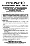
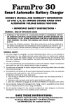
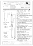
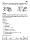
Owner’s Manual
BHT-1
Baler Hay Moisture Tester
Part No. 07150
Unpacking
1. The BHT-1 is comprised of a display module (A) with mounting bracket and
2 knobs, a 10 ft. power cable (B) with fuse, a 25 ft. shielded sensor cable
(C), and a moisture sensor assembly (D) with mounting hardware and drilling template. The 2 sheet metal screws (j) for mounting the display module
bracket are packed with the moisture sensor assembly. Identify all parts
illustrated below in Figure 1 before beginning to install.
FIGURE 1
(A)
(B)
(C)
b
(D)
Moisture Sensor
Assembly (D):
a. (2) Contact bolts
b. (1) Plate
c. (2) Sm. plastic bushings
d. (2) Lg. plastic washers
e. (6) Flat washers
f. (2) Lg. lock washers
g. (4) Lg. nuts
h. (2) Flathead bolts
i. (2) Sm. lock washers
j. (2) Sm. nuts
k. (2) Sheet metal screws
for bracket
l. Sensor cable
c
d
a
e f
g e
l
h
e g
k
i j
1
Installation of the Moisture Sensor
On a Conventional Square Baler:
1. Locate a flat spot between 12” to 24” from the rear of the chamber, about
halfway up the side, on the UNCUT SIDE of the chamber.
NOTE: Readings from the cut side of the bale will result in greater
variations of readings and overall higher readings.
2. Tape the drilling template onto the flat location and drill all holes, using the
drill sizes indicated on the template. File any burrs from the holes.
NOTE: The beveled (leading) edge of the sensor plate must face the
plunger (opposite direction of bale movement).
NOTE: The sensor plate must mount flat and tight to the bale chamber
wall!
3. Mount the sensor assembly using hardware provided. Follow diagram in
Figure 2.
NOTE: Make sure that two (2) electrode contacts (carriage bolts) are not
touching any part of the metal bale chamber, by using the insulating
bushings and washers. Secure tightly with one big nut on each bolt.
NOTE: Make sure that the beveled (leading) edge of the sensor plate is
fastened flat and tight to the chamber wall. Secure tightly with two (2)
flat head bolts. (If the leading edge is not secured flat and tight to the
wall, hay passing under extreme pressure will pry up the sensor plate.)
4. Assemble a ring terminal on the sensor cable to each contact bolt. Place
ring terminal between two (2) metal washers and secure tightly with the last
two nuts (see Figure 3).
5. Route the sensor cable to the hitch area of the baler so that it does not
interfere with any moving parts. Secure the cable with nylon ties or tape.
NOTE: Use attached plug cover tethered to connector to keep out dirt
and moisture!
On a Large Square Baler:
1. Use the same instructions as above, except we recommend that you add a
1/4” thick piece of strap iron in front of the sensor plate’s beveled (leading)
edge. This will provide additional protection to the sensor plate.
On a Round Baler:
1. Locate a flat spot on the sidewall or tailgate, as low as possible to the bottom, on either side of the baler. Use the same instructions as above.
NOTE: The beveled (leading) edge of the sensor plate must face the
pickup.
NOTE: Hay will begin to pass over the sensor as soon as approximately 1/4 of the bale is formed.
2
FIGURE 2
FIGURE 3
Installation of the Display Module
1. Select a location (a flat surface) in the cab where the display can be viewed
while baling.
2. Using the mounting bracket as a template, mark and drill 3/32” pilot holes,
and secure the bracket with the two (2) sheet metal screws.
3. Mount Display Module to bracket with adjusting knobs.
4. Locate a positive (+) 12-volt power wire or terminal that is controlled by the
tractor’s ignition switch and attach the RED wire of the power supply cable
to it.
5. Attach the other wire of the power supply cable to ground (frame).
6. Plug the power cable connector into the Display Module’s 2-pin connector.
7. Plug the sensor cable connector into the module’s 3-pin connector.
3
Operating Instructions –
Button Functions (See Figure 4)
1. Moisture: Press Moisture button to turn meter on. The BHT-1 displays continuous moisture readings when turned on. The unit should display 00.0 if
the bale chamber is empty. The BHT-1 reads moisture between 8% and
40%. Readings below 8% are displayed as 00.0. Readings above 40% are
displayed a 99.9.
NOTE: The BHT-1 takes several readings before displaying their average every two seconds.
2. Backlighting: When the unit is on, press the Light button to turn backlighting of the display on or off. When the module is turned off and later turned
on, it will remember the backlighting mode of when it was last operating.
3. Calibration Check and Reset: When the unit is on, press the Check button
to recalibrate the moisture circuit to the current conditions of the sensor and
its environment. The BHT-1 will automatically adjust to dirty sensor contacts
and the relative humidity inside the chamber. We suggest that it be common
practice to recalibrate the meter every time the unit is turned on.
If the bale chamber is empty, the unit will display approximately 12.0 after
recalibration, signifying correct calibration.
If there is an obstruction, such as a bale, in the chamber or if the sensor
electrodes are very dirty, the unit will display 99.9. If the bale is removed,
and the meter still reads 99.9, the electrodes must be cleaned. (See Care
and Maintenance). If the meter must be used before the electrodes can be
cleaned, the unit will still operate using its last calibration points.
4. To Turn Off: Press Moisture button.
FIGURE 4
Backlight
Calibration Check
On/Off (Moisture)
4
Testing Procedure and Information
1. While a bale is being formed in the bale chamber, the BHT-1 reads and
averages several tests and displays these results every two seconds. Typically, moisture readings will vary several percentage points in a single bale.
Windrows are never the same moisture from top to bottom. Usually, they
will be wetter at the top, because of dew, or drier, because of sun and wind.
Usually, hay that is ready to bale varies less than hay that is not yet ready.
2. Continuous readings from the BHT-1 and other manufacturers’ meters will
usually be higher than reading from handheld, portable or probe testers.
The BHT-1 will probably read about 2-3 percentage points higher on average, and even higher for large, square bales, depending on conditions.
3. Do not be concerned that these differences exist. Rather, develop a feel for
an acceptable range of moisture for baling, based on your meter’s readings.
Establish an appropriate range by spot checking new bales with a portable
probe tester, such as a Farmex HT-Pro or DHT-1.
4. Hay moisture can vary considerably from one part of a field to another. (See
Testing Information.) If the moisture range displayed by the BHT-1 increases above your acceptable limits, stop baling and analyze the field conditions
to determine why. You may not want to continue baling in this area of the
field.
Variables Affecting Moisture Readings
Understanding the many variables that affect the readings of your BHT-1 will
help you get the most from your meter.
1. Field conditions: soil moisture, high or low areas, swales and shady areas
all affect hay moisture within the same field.
2. Hay varieties, leaf-to-stem ratios, crop maturity and different cuttings contribute to widely varying moisture distribution in hay plants.
3. Harvesting variables: bale density, windrow size and shape, time of day, hay
temperature and overall climatic conditions affect moisture readings. High
humidity with cloud cover contributes to more variations in moisture readings than a dry, sunny day with a slight breeze.
4. Some preservatives increase conductivity initially. Until the preservative is
absorbed, usually in 1-2 days, it may cause readings to be 2-4 points above
the same hay which is untreated.
IMPORTANT: Because of the numerous variables which affect your
BHT-1’s readings, the indicated moisture content should not be used
as an absolute, quantitative measurement. Your tester’s readings are,
however, very useful guidelines for safely baling and storing hay.
5
Care and Maintenance
1. After each use (and especially after the harvest season), always remove
the Display Module (if it is not inside a dry cab) and store in a clean and dry
place.
2. Always use plug cover on sensor cable connector to keep out dirt and moisture!
3. The stainless contacts of the moisture sensor should be kept clean for best
results. Clean with fine steel wool and/or mineral spirits or alcohol. Dirty
sensor contacts can cause lower readings.
4. Check all nuts and bolts on sensor plate assembly and tighten, if necessary. Make sure that the leading edge is secured flat and tight to the
chamber wall.
6
Troubleshooting and
Warranty Procedure
1. If the unit will not turn on, it is not getting power. Check power cord installation and connectors. Check 2 amp fuse on power cable and replace, if
necessary.
2. If the meter displays 00.0 at all times (while baling), there is an open circuit
between the display module and the sensor. Check that the cable is not
damaged and that the connector is plugged securely. The connector may
be corroded and need replacing. Also check that the sensor cable ring terminals are fastened tightly to the electrode posts. (The meter should still
read about 12.0 when recalibrated, even if there is an open circuit to the
sensor.)
3. If the meter displays 99.9 at all times (while baling), there is a short in the
sensor cable or at the electrodes. (The meter will not read 12.0 when recalibration is attempted, but will always display 99.9). Check for cable damage.
4. If the meter displays 8.0 when the bale chamber is empty, electrodes are
dirty and need cleaning. (The meter will also read 99.9 when recalibration
is attempted, if electrodes are dirty.) Clean and recalibrate.
5. If all else fails, please read this manual again! Carefully.
Warranty
The Farmex™ BHT-1 Hay Moisture Tester is guaranteed to be free from
defects in materials and workmanship for one year from date of retail purchase. This warranty does not cover the battery or damage resulting from
misuse, neglect, accident or improper installation or maintenance. This
warranty does not apply to any product which has been repaired or altered
outside the factory.
The foregoing warranty is exclusive and in lieu of all other warranties of
merchantability, fitness for purpose and any other type, whether expressed
or implied. AgraTronix neither assumes nor authorizes anyone to assume
for it any other obligation or liability in connection with its product and will
not be liable for consequential damages.
7
ASK ABOUT OUR OTHER MOISTURE TESTERS
Ask your local retailer for more information
or call us direct at 800-821-9542.
TEN MODELS FOR GRAIN, HAY OR SILAGE
Windrow Hay Tester
HT-Pro Hay Moisture Tester
• Test Hay Moisture Content
Right in the Windrow
• 13% to 70% Measuring Range
• Quickly Measures Loose Hay
• Calibration Clip Included That Calibrates
Electronics and the Probe Sensor
• 8% to 44% Moisture Range
• LED Backlit Display for Low Light
Operation
and Forage from a Windrow
10375 State Route 43
Streetsboro, OH 44241 USA
(800) 821-9542 • 1 (330) 562-2222
http://www.agratronix.com
8
Manual del Propietario
BHT-1
Medidor de Humedad
Para Fardos de Heno
Part No. 07150
Desembalando
1. El BHT-1 comprende un mòdulo de muestra (A) con soporte de montaje y 2
dibujos, a 10 ft. cable de poder (B) con fusible, a 25 ft. cable sensor blindado
(C), montaje de sensor de humedad (D) con montaje hardware y plantilla
instructiva. Los 2 tornillos de metal (j) para montaje muestra el mòdulo de
soporte embalado con el montaje del sensor de humedad. Identificar todas
las partes ilustradas en Figura 1 antes de empezar a instalar.
FIGURA 1
(A)
(B)
(C)
b
(D)
Montaje del Sensor
de Humedad (D):
a. (2) Pernos del contacto
b. (1) Chapa
c. (2) Sm. buje plàstico
d. (2) Lg. arandela plàstico
e. (6) Arandela plana
f. (2) Lg. A presión
g. (4) Lg. tuercas
h. (2) Perno cabeza plana
i. (2) Sm. A presiòn
j. (2) Sm. tuercas
k. (2) tornillo de metal
para soporte
l. Cable sensor
c
d
a
e f
g e
l
h
e g
k
i j
9
Instalaciòn del Sensor de Humedad
Sobre un fardo cuadrado convencional:
1. Ubìque un lugar plano entre 12” a 24” de la parte trasera de la càmara, a
medio camino, sobre el lado UNCUT de la càmara.
NOTA: Lecturas desde el corte lateral del fardo resultaran en variaciónes mayores de lecturas y, sobre todo, en lecturas superiores.
2. Grabe la plantilla de perforación en la ubicación plana y taladre todos los
agujeros, usando el taladro de tamaño indicado en la plantilla. Archive cualquier zumbido de los agujeros.
NOTA: El borde biselado (principal) del sensor de la placa debe afrontar el émbolo (sentido contrario de circulación del fardo).
NOTA: ¡El sensor de la placa debe montar plano y apretado a la cámara de pared del fardo!
3. Monte el sensor usando el hardware proporcionado. Siga el diagrama de la
Figura 2.
NOTA: Asegùrese que los dos (2) contactos de electrodos (porta pernos)
no esten tocando ninguna parte de la càmara de metal del fardo, al usar
los bujes y arandelas aislantes. Ajuste con una gran tuerca cada perno.
NOTA: Asegúrese de que el borde de la superficie biselada (principal)
de la placa del sensor se cierra plana y ajustados a la cámara de pared
Ajuste con dos pernos (2) cabeza plana. (Si el borde principal no esta
ajustado a la pared, el heno que pasa bajo extrema presión husmearà
el sensor de la chapa.)
4. Montaje de un terminal de anillo en el cable del sensor de contacto de cada
perno. Colocar el terminal de anillos entre dos (2) de arandelas de metal y
ajustar con las últimas dos tuercas (véase la figura 3.)
5. Guiar el cable del sensor de enganche a la zona de la agavilladora para
que no interfiera con las piezas en movimiento. Asegure el cable con cinta
de nylon o lazos.
NOTA: Use adjunto tapas de enchufe atados para mantener fuera la
suciedad y la humedad!
Sobre un extenso fardo cuadrado:
1. Use las mismas instrucciones de arriba, excepto que te sugerimos añadir
un 1 / 4 “de grosor pedazo de correa de hierro al frente del borde del sensor
de la placa biselada (principal). Esto proporcionarà una protecciòn adicional a la placa del sensor.
Sobre un fardo redondeado:
1. Ubique un sitio liso en el lateral o en la puerta del maletero, lo más bajo
posible a la parte inferior, a ambos lados de la agavilladora. Utilizar las mismas instrucciones que en el caso anterior.
NOTA: El borde biselado (principal) de la placa del sensor debe quedar
con la cara frente la camioneta.
NOTA: El heno empezarà a pasar por encima de los sensores tan pronto como se forme 1 / 4 del fardo.
10
FIGURA 2
FIGURA 3
Instalaciòn del Mòdulo de Visualizaciòn
1. Elija una ubicación (una superficie plana) en la cabina cuando la pantalla
pueda verse mientras enfarda.
2. Utilìze el soporte de montaje como plantilla, la marca y la sonda 3 / 32 “
agujeros pilotos, y asegure con el soporte de las dos (2) hojas de tornillos
de metal.
3. Módulo de visualización para montar el soporte con ajuste de perillas.
4. Localizar un cable positivo (+) de 12 voltios de potencia o que la terminal
estè controlado por el interruptor de encendido del tractor y adjùnto al
cable ROJO de suministro de energía a la misma.
4. Conecte el otro cable de la fuente de alimentación de cable a tierra
(armazòn).
5. Módulo de visualización para montar el soporte con ajuste de perillas.
6. Enchufe el cable del sensor en el conector del mòdulo 3 de patillas de
conectores.
11
Instrucciones de Operaciòn –
Funciones de Botòn (ver Figura 4)
1. Humedad: Presione el botòn de humedad para activar el contador. El
BHT-1 muestra las lecturas de humedad en forma continua cuando se enciende. La unidad debería mostrar 00,0 si la cámara del fardo está vacía.
El BHT-1 lectura humedad entre 8% y 40%. Lecturas por debajo de 8% se
muestran como 00.0. Lecturas sobre 40% se muestran como 99.9.
NOTA: El BHT-1 toma varias lecturas antes de mostrar sus promedios
cada dos segundos.
2. Retroiluminaciòn: Cuando la unidad está encendida, pulse el botón para
activar la Luz de retroiluminación de la pantalla o para desactivar. Cuando
el módulo estè apagado y encendido más tarde, recordarà el modo de la
retroiluminación cuando se actualizó y operò por última vez.
3. Revisiòn de calibraciòn y reajuste: Cuando la unidad está encendida,
pulse el botón Check para recalibrar la humedad del circuito a las actuales
condiciones de los sensores y su entorno. El BHT-1 se ajustará automáticamente a los contactos sucios y al sensor de humedad relativa dentro de
la cámara. Sugerimos que se habitùe a recalibrar el medidor cada vez que
la unidad está encendida.
Si la cámara del fardo está vacía, la unidad mostrará aproximadamente
12,0 después de la recalibración, significando la calibración correcta.
Si hay una obstrucción, como un fardo, en la cámara o si el sensor electromagnético está muy sucio, la unidad mostrará 99,9. Si el fardo es retirado
y el contador aùn lectura 99.9, los electrodos deben ser limpiados. (ver
Cuidado y Mantenimiento). Si el contador va a ser usado antes que los
electrodes sean limpiados, la unidad aún funcionarà usando la última calibración.
4. Para Apagar: Oprima el botòn humedad.
FIGURA 4
Backlight
On/Off (Moisture)
12
Calibration Check
Procedimiento de Prueba e Informaciòn
1. Mientras que un fardo se está formando en la cámara de fardo, el BHT-1 lee
y promeda varias pruebas y muestra estos resultados cada dos segundos.
Normalmente, las lecturas de humedad variarán varios puntos porcentuales en un solo fardo. Montìculos nùnca tienen la misma humedad arriba
que abajo. Usualmente, ellos estaran más húmedos en la parte superior,
a causa del rocío, o secas, por de sol y el viento. Usualmente, el heno que
está listo para enfardar varía menos que el heno que todavía no está listo.
2. Lecturas contìnuas desde el BHT-1 y otros contadores de fàbrica habitualmente serán mayores que las lecturas de mano, portátiles o pruebas de
medición. El BHT-1 probablemente leerà acerca de 2-4 puntos porcentuales mayores en promedio, y aún más para los grandes, fardos cuadrados,
dependiendo de las condiciones
3. No debe preocupar el hecho de que estas diferencias, existan. Por el contrario, desarrollar una idea de un margen aceptable de humedad para el
prensado, en base a lecturas de su medidor. Establecer un margen adecuado por comprobar in situ los nuevos fardos con un analizador de sonda
portátil, como un Farmex HT-Pro o DHT -1.
4. La humedad del heno puede variar considerablemente de una parte del
campo a otra. (Ver información de prueba.). Si el grado de humedad mostrado por el BHT-1 aumenta por encima de sus límites aceptables, detenga el
enfardado y analìze las condiciones del campo para determinar el Por qué.
You may not want to continue baling in this area of the field. Es posible que
no desee continuar enfardando en esta área del campo.
Variables Que Afectan Las Lecturas de Humedad
Comprender las muchas variables que afectan a las lecturas de su BHT-1 le
ayudará a disfrutar al máximo de su contador.
1. Condiciones de campo: La humedad del suelo, zonas altas o bajas, swales y
àreas sombreadas afectan la humedad del heno dentro del mismo campo.
2. Variedades de heno variedades, hojas para detener coeficientes, madurez
de cultivos y diferentes cortes contribuyen a la gran diversidad en la distribución de la humedad en plantas de heno.
3. Variables de la Cosecha: Densidad del fardo, tamaño y forma del montìculo, tiempo diurno, temperatura del heno y en general, las condiciones
climáticas afectan las lecturas de humedad. Alta humedad con nubosidad
contribuye a màs variaciones en las lecturas de humedad que un dia seco,
soleado con una ligera brisa.
4. Algunos conservantes incrementan la productividad inicialmente. Hasta que
el conservante sea absorbido, por lo general en 1-2 días, puede hacer que
las lecturas esten 2-4 puntos por encima del mismo que es heno sin tratar.
IMPORTANTE: Debido a las numerosas variables que afectan las lecturas de su BHT-1, se indica que el contenido de humedad no debe
utilizarse como un absoluto, medición cuantitativa. Sus probadores
de lecturas son, sin embargo, muy útiles en condiciones de seguridad
para enfardar y almacenar heno.
Cuidado y Mantenimiento
1. Despuès de cada uso (sobre todo despuès de la cosecha), siempre quìte el
módulo de visualización (si no esta dentro de una cabina seca) y almacene
en un lugar seco y limpio.
2. Use siempre enchufe con funda en el conector de cable del sensor, para
mantener fuera la suciedad y la humedad!
3. El contacto inoxidable del sensor de humedad debe mantenerse limpio
para obtener mejores resultados. Limpie con lana de acero fino y/o bebidas
espírituosas o alcohol. Sensor de contacto sucio puede causar bajas
lecturas.
4. Revisar todas las tuercas y pernos en la placa de montaje del sensor
y ajustar, en caso de ser necesario. Asegúrese de que la punta estè
plana y ajustados a la cámara de pared.
14
Localizaciòn de Problemas
y Procedimientos de Garantìa
1. Si la unidad no enciende, no le esta llegando energìa. Verifìque el cable de
conexiòn y los instaladores. Verifìque el fusible de 2 amperios del cable de
alimentación y reemplàzelo de ser necesario.
2. Si el contador muestra 00.0 todo el tiempo (mientras enfarda), hay un circuito abierto entre el mòdulo de la pantalla y el sensor. Verifìque que el
cable no esta dañado y que el conector esta enchufado con seguridad. El
conector puede estar corrìdo y necesìta reemplazarse. También verifique
que el cable del sensor de anillos de terminales están sujetos fuertemente
a los postes de electrodos. (El contador deberìa lecturar aùn 12.0 cuando
se recalibrò, aùn si hubiese un circuìto abierto al sensor.)
3. Si el contador muestra 99.9 todo el tiempo (mientras enfarda), hay un corte
en el cable del sensor o en los electrodos. (El contador no lecturarà 12.0
cuando se intente recalibar, pero siempre mostrarà 99.9). Verifìque si hay
un cable dañado.
4. Si el contador muestra 8.0 cuando la càmara del fardo esta vacìa, los electrodos estan sucios y necesitan limpiarse. (El contador tambièn lecturarà
99.9 cuando se intente recalibrar, si los electrodos estan sucios.) limpie y
recalibre.
5. ¡Si todo lo demás falla, por favor, lea este manual de nuevo!
Cuidadosamente.
Garantìa
El Farmex™ BHT-1 Medidor de Humedad para Heno esta garantizado
para estar libre de defectos de terminaciòn y fabricaciòn por un año desde
la fecha de su compra. Esta garantìa no cubre la baterìa o daños resultante de uso erròneo, negligencia, accidente o instalaciòn o servicio
inapropiado. Esta garantìa no es vàlida para todo producto que ha sido
reparado o alterado fuera de la fàbrica.
La garantìa precedente es exclusiva y en lugar de otras garantìas de mercantibilidad, idoneidad para fines y otros tipos, esta expresada e implicada.
AgraTronix tampoco assume ni autoriza a nadie a asumir por èl cualquier
obligaciòn o responsabilidad relacionada con este producto y no se responsabiliza por daños colaterales.
15
PREGUNTE SOBRE NUESTROS MEDIDORES
DE HUMEDAD
Para mayor información pregunte a su proveedor o
llàmenos directamente al 800-821-9542.
DIEZ MODELOS PARA GRANO, HENO O FORRAJE
Windrow Hay Tester
HT-Pro
Probador del Heno de la
Hilera
Medidor de Humedad Para Heno
•
•
•
• Pruebe la derecha de contenido
de agua del heno en la hilera
• Rango de medición del 13% a del 70%
• Mide rápidamente el heno y el forraje
flojos de una hilera
Incluye pinza de calibración que calibra
electronicos y el sensor de sonda
8% a 44% rango de humedad
LED backlit con tenue luz de operación
10375 State Route 43
Streetsboro, OH 44241 USA
(800) 821-9542 • 1 (330) 562-2222
http://www.agratronix.com
16
DOCU-M0101 12-08