1
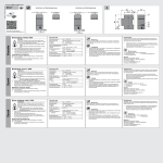
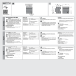
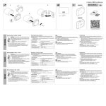
HA-M-0.6.1
6254/0.6
www.abb.es/freeathome
Deutsch
Heizungsaktor 6-fach, REG
WARNUNG
Bei direktem oder indirektem Kontakt mit spannungsführenden Teilen kommt es zu einer gefährlichen
Körperdurchströmung. Elektrischer Schock, Verbrennungen oder der Tod können die Folge sein.
ØVor Montage /Demontage Netzspannung freischalten!
ØArbeiten am 230 V-Netz nur von Fachpersonal
ausführen lassen.
n Montageanleitung sorgfältig lesen und aufbewahren.
nWeitere Benutzerinformationen unter www.abb.com/freeathome
oder durch Scannen des QR-Codes.
nInformationen zur Systemeinbindung siehe Systemhandbuch
(www.abb.com/freeathome).
Bestimmungsgemäßer Gebrauch
Technische Daten
Inbetriebnahme
Stromversorgung
21 ... 30 V DC
Busanschluss
Busanschlussklemme, schraubenlos
Nennspannung
24 ... 230 V AC, 50/60 Hz
Nennstrom je Ausgang
160 mA bei Tu = 45 C°
Einschaltstrom je
Ausgang
max. 750 mA bei Tu = 60 C°
Anschlussklemme
Ausgang
Kombikopf-Schraubklemmen (PZ 1)
0,2 ... 4 mm² feindrahtig
0,2 ... 6 mm² eindrahtig
Schutzart
IP20
Umgebungstemperatur
- 5 °C – + 45 °C
Lagertemperatur
- 20 °C – + 70 °C
Das Gerät dient zum Ansteuern von 24 V oder 230 V thermoelektrischen Stellantrieben in Heiz- oder Kühlsystemen.
nAusführliche Informationen zum Funktionsumfang siehe Technisches Handbuch (siehe QR-Code)
English
Heating actuator 6gang, MDRC
WARNING
Dangerous currents flow through the body when coming into direct or indirect contact with live components.
This can result in electric shock, burns or even death.
ØDisconnect the mains power supply prior to installation/
disassembly!
ØPermit work on the 230 V supply system to be
performed only by specialist staff.
nPlease read the mounting instructions carefully and keep them
for future use.
nAdditional user information is available at
www.abb.com/freeathome or by scanning the QR code.
nFor information on system integration please see the system
manual (www.abb.com/freeathome).
Intended use
The device serves for activating 24 V or 230 V thermoelectric actuating drives in heating or cooling systems.
nFor detailed information about the range of functions see the
technical reference manual (see QR code).
Español
Actuador de calefacción 6 elementos, REG
ADVERTENCIA
En caso de entrar en contacto, directa o indirectamente, con componentes por los que circule una corriente
eléctrica, se puede sufrir una descarga eléctrica
peligrosa, cuyo resultado puede ser choque eléctrico,
quemaduras o, incluso, la muerte.
Ø
¡Desconecte la tensión de red antes de proceder al
montaje o desmontaje!
ØEncargue los trabajos en la red eléctrica de 230 V
solo al personal técnico competente.
nLea detenidamente y guarde en lugar seguro el manual de
montaje.
nMás información para usuarios en www.abb.com/freeathome o
escaneando el código QR.
nPara más información sobre la integración en el sistema,
consulte el manual del sistema (www.abb.com/freeathome).
Uso conforme al fin previsto
El aparato sirve para controlar accionamientos termoeléctricos
reguladores de 24 o de 230 V con sistemas de calor o frío.
nSi desea información más detallada sobre las funciones,
consulte el manual técnico (véase el código QR).
Attuatore riscaldamento 6x, REG
Italiano
2CDG 941 147 P0001 / 28.04.2014
free@home
Das Gerät nur auf Hutschienen nach DIN EN 60715 installieren.
Klebeschild abziehen und in Liste einkleben (bei System Access
Point).
Anschluss
nDer elektrische Anschluss erfolgt über Schraubklemmen.
Die Klemmenbezeichnungen befinden sich auf dem Gehäuse.
nDie Verbindung zur Buslinie erfolgt über die mitgelieferte Busanschlussklemme (rot/schwarz).
nJeweils 3 Ausgänge (A-C, D-F) sind gemeinsam abgesichert
und werden über eine Phase versorgt.
nEs können mehrere thermoelektrische Stellantriebe parallel an
einen Ausgang angeschlossen werden. Beim Parallelschalten
mehrerer Stellantriebe ist zu beachten, dass der maximale
Einschaltstrom bzw. Nennstrom nicht überschritten werden darf.
n Technische Daten des Stellantriebs beachten!
Technical data
Power supply
Mounting
Bus connection
Bus connecting terminal, screwless
Nominal voltage
24 ... 230 V AC, 50/60 Hz
Nominal current per
output
160 mA at Tu = 45C°
Install the device only on mounting rails according to
DIN EN 60715. Remove the stick-on label and glue it into the list
(at System Access Point).
Max. 750 mA at Tu = 60C°
Connection
Inrush current per output
Connecting terminal
Output
Combi-head screw-type terminal
(PZ 1)
0.2 ... 4 mm² fine-wire
0.2 ... 6 mm² single-wire
Protection type
IP20
Ambient temperature
-5 °C – +45 °C
Storage temperature
-20 °C – +70 °C
nThe electrical connection is made via screw terminals.
The description of the terminals is found on the housing.
nThe connection to the bus line is made via the enclosed bus
connection terminal (red/black).
nThree outputs (A-C, D-F) each are protected together and are
supplied via one phase.
nSeveral thermoelectric actuating drives can be connected in
parallel to one output. When connecting several actuating
drives in parallel it should ensured that the maximum inrush
current or nominal current is not exceeded.
n The technical data of the actuating drives must be observed!
Datos técnicos
21 ... 30 V c.c.
Conexión de bus
Borne de conexión de bus, sin
tornillo
Tensión nominal
24 ... 230 V c.a., 50/60 Hz
Corriente nominal por
salida
160 mA con Tent = 45 °C
máx. 750 mA con Tent = 60 °C
Borne de conexión
Salida
Bornes roscados de cabeza combi
(PZ 1)
0,2 ... 4 mm² flexible
0,2 ... 6 mm² de un hilo
Grado de protección
IP20
Temperatura ambiente
-5 °C – +45 °C
Temperatura
de almacenamiento
-20 °C – +70 °C
Montaje
Instale el aparato sobre carriles DIN según la norma EN 60715.
Retire la etiqueta adhesiva y péguela en la lista (en System Access
Point).
Conexión
nLa conexión eléctrica se realiza mediante bornes roscados.
Las denominaciones de los bornes se encuentran en la carcasa.
nLa conexión con la línea de bus se efectúa con el borne de
conexión de bus suministrado (rojo/negro).
nCada 3 salidas (A-C, D-F) cuentan con una protección común
y son alimentadas por una fase.
nSe pueden conectar varios accionamientos termoeléctricos
reguladores en paralelo a una misma salida. Al conectar en
paralelo varios accionamientos reguladores, se debe tener
en cuenta que no se debe superar la corriente de conexión o
corriente nominal máximas.
n ¡Obsérvense los datos técnicos del accionamiento regulador"
Dati tecnici
21 ... 30 V DC
Collegamento bus
Morsetto di allacciamento bus,
senza viti
Tensione nominale
24 ... 230 V AC, 50/60 Hz
Tensione nominale per
ogni uscita
160 mA con Tu = 45 C°
Uso conforme alle prescrizioni
Tipo di protezione
IP20
Temperatura ambiente
- 5 °C – + 45 °C
Temperatura
di immagazzinamento
- 20 °C – + 70 °C
Morsetto
Uscita
Bedienung
1 = Geräteidentifikation während der Inbetriebnahme
2 = Identifikations-LED
3 = Busanschlussklemme
4 = Anschlussklemmen
Service
ABB STOTZ-KONTAKT GmbH
Eppelheimer Straße 82, 69123 Heidelberg
Tel. DE 0800 3733 28 4
Tel. CH +41 58 586 07 00
E-Mail: [email protected]
www.abb.com/freeathome
The device connected to the busline is automatically recognized by
the system after a few seconds. The devices must be parameterised for the use of the functions.
nDetailed information about commissioning and parameterization is available in the technical reference manual and the
online help of the "System Access Point"
(www.abb.com/freeathome).
n Firmware update is carried out via the System Access Point.
Operation
1 = Device identification during commissioning
2 = Identifications-LED
3 = Bus connection terminal
4 = Connecting terminals
Service
ABB STOTZ-KONTAKT GmbH
Eppelheimer Straße 82, 69123 Heidelberg, Germany
Tel. +49 2351 956-1600
E-mail: [email protected]
www.abb.com/freeathome
El sistema reconoce automáticamente tras unos segundos el
aparato que se conecta a la línea de bus. Para la ejecución de las
funciones adicionales es necesario parametrizar los aparatos.
nPodrá encontrar información detallada sobre la puesta en
servicio y sobre la parametrización en el manual técnico y en
la ayuda online del “System Access Point” o punto de acceso
del sistema (www.abb.com/freeathome).
nLa actualización del firmware se realiza a través del System
Access Point (punto de acceso del sistema).
Manejo
1 = Identificación de los aparatos durante la puesta en servicio
2 = LED de identificación
3 = Borne de conexión de bus
4 = Borne de conexión
Servicio postventa
ABB STOTZ-KONTAKT GmbH
Eppelheimer Straße 82, 69123 Heidelberg
Tel. +34 902 11 15 11
E-Mail: [email protected]
www.abb.com/freeathome
Messa in funzione
Alimentazione elettrica
Corrente di inserzione
per ogni uscita
nAusführliche Informationen zu Inbetriebnahme und Parametrierung befinden sich im Technischen Handbuch und in der
Onlinehilfe des „System Access Point“
(www.abb.com/freeathome).
n Firmware-Update erfolgt über System Access Point.
Puesta en servicio
Alimentación
de corriente
Corriente de conexión
por salida
Das an die Buslinie angeschlossene Gerät wird nach einigen Sekunden automatisch vom System erkannt. Die Geräte müssen zur
Ausführung der Funktionen parametriert werden.
Commissioning
21 ... 30 V DC
AVVERTIMENTO
Il contatto diretto o indiretto con parti attraversate da
corrente elettrica provoca pericolosi flussi di corrente
attraverso il corpo. Le conseguenze possono essere
folgorazione, ustioni o morte.
Ø
Prima del montaggio o dello smontaggio scollegare la
tensione di rete!
ØAffidare gli interventi sulla rete elettrica a 230 V
esclusivamente a personale specializzato.
n Leggere e conservare con cura le istruzioni per il montaggio.
nMaggiori informazioni per l'utente disponibili sul sito
www.abb.com/freeathome o tramite scansione del codice QR.
nPer informazioni sull'integrazione nel sistema vedere il manuale del sistema (www.abb.com/freeathome).
L'apparecchio è stato progettato per l'attivazione di attuatori
termoelettrici a 24 V o 230 V installati in sistemi di riscaldamento o
raffreddamento.
nPer informazioni dettagliate sulle funzioni disponibili consultare
il manuale tecnico (vedere il codice QR).
Montage
Montaggio
Installare l'apparecchio esclusivamente su guide DIN conformi a
DIN EN 60715. Staccare l'etichetta adesiva e incollarla nella lista
(per System Access Point).
Collegamento
max 750 mA con Tu = 60 C°
Morsetti a vite con testa a intaglio
(PZ 1)
0,2 ... 4 mm² a filo fine
0,2 ... 6 mm² monofilo
nIl collegamento elettrico è realizzato tramite morsetti a vite. I
codici dei morsetti sono riportati sulla scatola.
nIl collegamento alla linea bus è realizzato tramite il morsetto
bus allegato (rosso/nero).
nPer ogni 3 uscite (A-C, D-F) è predisposta una protezione e
sono alimentate da una fase.
nAd una uscita si possono collegare in parallelo più attuatori
termoelettrici. In caso di commutazione parallela di più attuatori
attenzione a non superare la corrente d'inserzione o la tensione nominale massima.
n Osservare le specifiche tecniche dell'attuatore!
L'apparecchio collegato alla linea bus viene rilevato automaticamente
dal sistema dopo alcuni secondi. L'apparecchio collegato alla linea bus
viene rilevato automaticamente dal sistema dopo alcuni secondi. Per
utilizzare le funzioni è necessario parametrizzare gli apparecchi.
nPer informazioni dettagliate sulla messa in servizio e sulla parametrizzazione consultare il manuale tecnico o la guida online del
"System Access Point" (www.abb.com/freeathome).
nL'aggiornamento firmware avviene tramite System Access Point.
Uso
1 = identificazione dell'apparecchio durante la messa in servizio
2 = LED identificativo
3 = Morsetto di allacciamento bus
4 = Morsetti
Service
ABB STOTZ-KONTAKT GmbH
Eppelheimer Straße 82, D-69123 Heidelberg
Tel. IT 0800 55 1166
Tel. CH +41 58 586 07 00
E-Mail: [email protected]
www.abb.com/freeathome
HA-M-0.6.1
6254/0.6
www.abb.es/freeathome
Français
Actionneur de chauffage 6x, AES
Avertissement
Un contact direct ou indirect avec des pièces sous tension entraîne un passage de courant dangereux dans
le corps. Celui-ci risque d’entraîner un choc électrique,
des brûlures ou la mort.
Ø
Déconnecter la tension secteur avant tout montage/
démontage !
ØFaire réaliser toute intervention sur l'alimentation
électrique en 230 V uniquement par des techniciens
spécialisés.
nLes instructions de montage sont à lire attentivement et à
conserver.
nDes informations utilisateurs supplémentaires sont disponibles
sur le site www.abb.com/freeathome ou en scannant le code QR.
nPour des informations sur l’intégration du système, voir le
manuel système (www.abb.com/freeathome).
Caractéristiques techniques
Alimentation électrique
21 ... 30 V c.c.
Raccordement bus
Borne de connexion du bus, sans vis
Tension nominale
24 ... 230 V c.a., 50/60 Hz
Intensité nominale par
sortie
160 mA à Tu = 45 C°
Courant de fermeture
par sortie
750 mA max. à Tu = 60 C°
Borne de raccordement
Sortie
Bornes à vis à tête combinée (PZ 1)
0,2 ... 4 mm² à conducteur fin
0,2 ... 6 mm² à un conducteur
Type de protection
IP20
Température ambiante
- 5 °C – + 45 °C
Température
de stockage
- 20 °C – + 70 °C
Utilisation conforme
L'appareil sert à actionner des servocommandes thermoélectriques de
24 V ou 230 V dans des systèmes de chauffage ou de refroidissement.
nDes informations détaillées sur la gamme des fonctions sont
disponibles dans le manuel technique (voir le code QR).
6 路供暖执行器,REG
中文
警告
直接或间接接触导电零件时,可能有触电危险。可能造
成电击、灼伤或死亡。
Ø安装 / 拆卸前应先切断电源!
Ø仅可由专业人员在 230 V 电网上进行作业。
n 请仔细阅读并妥善保管安装说明书。
n更多用户信息请查询 www.abb.com/freeathome 或通过扫描 QR
码获取。
n系统连接信息请参见系统手册 (www.abb.com/freeathome)。
按规定使用
设备用于控制供暖或供冷系统中的 24 V 或 230 V 热点传动装置。
n功能范围的详细信息请参见技术手册(参见 QR 码)
Fator de aquecimento 6 vezes, REG
Português
2CDG 941 147 P0001 / 28.04.2014
free@home
Atenção
No caso de contato direto ou indireto com peças
condutoras de tensão, há uma perigosa passagem de
corrente pelo corpo. As consequências podem ser o
choque elétrico, queimaduras ou a morte.
ØAntes da montagem / desmontagem, desligar a tensão
da rede!
ØSomente o pessoal especializado deve executar os
trabalhos na rede 230 V.
n Ler e guardar com cuidado o manual de montagem.
nOutras informações para o utilizador sob
www.abb.com/freeathome ou escaneando os códigos QR.
nInformações sobre a conexão do sistema, ver o manual do
sistema (www.abb.com/freeathome).
Utilização conforme
O aparelho serve para comandar mecanismos de controlo termoelétricos 24 V ou 230 V nos sistemas de aquecimento ou arrefecimento.
nInformações detalhadas sobre a gama de funções, ver o
manual técnico (ver o código QR).
Mise en service
Montage
Installer uniquement l'appareil sur des rail DIN selon
DIN EN 60715. Retirer l’autocollant et le coller dans la liste (au
niveau de point d’accès système (System Access Point).
Raccordement
nLa connexion électrique se fait via des bornes à vis. L'identification des bornes se trouve sur le boîtier.
nLe raccordement à la ligne de bus se fait à l'aide de la borne
de raccordement du bus fournie (rouge/noir).
n3 sorties (A-C, D-F, etc.) sont protégées ensemble et sont
alimentées via une phase.
nPlusieurs servocommandes thermoélectriques peuvent être
connectées en parallèle à une sortie. Lors de la connexion
parallèle de plusieurs servocommandes, veiller à ne pas
dépasser le courant de fermeture maximal ou le courant nominal.
nObserver les caractéristiques techniques de la servocommande !
技术数据
21 ... 30 V DC
总线连接
总线连接端子,无螺丝
额定电压
24 ... 230 V AC, 50/60 Hz
各输出端额定电流
Tu = 45 C° 时,最大 160 mA
Tu = 60 C° 时,最大 750 mA
连接端子
输出端
组合头螺旋端子 (PZ 1)
0.2 ... 4 mm² 细线
0.2 ... 6 mm² 单线
保护方式
IP20
环境温度
-5 °C – +45 °C
储存温度
-20 °C – +70 °C
安装
设备仅安装在符合 DIN EN 60715 的支承轨道上。撕下不干胶标签
并贴入列表(系统接入点中)。
连接
n通过螺旋端子进行电气连接。接线夹名称位于外壳上。
n通过随附的总线连接端子(红/黑)连接至总线。
n每 3 个输出端 (A-C, D-F) 予以共同保护且通过一个相位进行供
电。
n可将多台电热传动装置并联至一个输出端。并联多台传动装置
时,必须注意:不得超过最大接通电流或额定电流。
n 请注意传动装置的技术数据!
Dados técnicos
Terminal de conexão do barramento,
sem parafuso
Tensão da rede
24 ... 230 V CA, 50/60 Hz
Corrente nominal por
saída
160 mA a Tu = 45 C°
Corrente de ligação por
saída
Commande
1 = identification d'appareil pendant la mise en service
2 = LED d'identification
3 = Borne de raccordement du bus
4 = Bornes de raccordement
Service
ABB STOTZ-KONTAKT GmbH
Eppelheimer Straße 82, 69123 Heidelberg
Tél. FR +49 2351 956-1600
Tél. CH +41 58 586 07 00
E-Mail : [email protected]
www.abb.com/freeathome
数秒钟后,系统将自动识别与总线连接的设备。为了执行辅助功
能,必须设置设备参数。
n调试和参数设置的详细信息位于技术手册和“系统接入点”在线帮
助中 (www.abb.com/freeathome)。
n 通过系统接入点更新固件。
操作
1 = 调试期间识别设备
2 = 识别式 LED
4 = 连接端子
3 = 总线连接端子
维修
ABB STOTZ-KONTAKT GmbH
Eppelheimer Straße 82, 69123 Heidelberg
电话:+86 400-820-9696
电子邮件:[email protected]
www.abb.com/freeathome
Colocação em funcionamento
Alimentação de corrente 21 ... 30 V CC
Conexão de barramento
nDes informations détaillées sur la mise en service et le paramétrage sont disponibles dans le manuel technique et l’aide en
ligne du "point d’accès système" (www.abb.com/freeathome).
nLa mise à jour du micrologiciel est réalisée par le biais du point
d’accès système.
调试
电源
各输出端接通电流
L’appareil raccordé à la ligne de bus est détecté automatiquement
par le système à l’issue de quelques secondes. Un paramétrage
des appareils en vue de l’exécution des fonctions est nécessaire.
máx. 750 mA a Tu = 60 C°
Terminal de ligação
Saída
Terminais de parafusos de cabeça
combinada (PZ 1)
0,2 ... 4 mm² fio fino
0,2 ... 6 mm² um fio
Classe de proteção
IP20
Temperatura ambiente
- 5 °C – + 45 °C
Temperatura
de armazenagem
- 20 °C – + 70 °C
Montagem
Só instalar o aparelho nos carris segundo DIN EN 60715. Remover
a placa adesiva e colá-la na lista (no System Access Point).
Ligação
nA conexão elétrica é feita através dos terminais de parafusos.
As denominações encontram-se na caixa.
nA conexão com a linha do barramento é feita através do terminal de conexão de barramento fornecido (vermelho/preto).
nRespectivamente 3 saídas (A-C, D-F) são protegidas em
conjunto e são alimentadas através de uma fase.
nVários mecanismos de controlo termoelétricos podem ser
conectados paralelamente numa saída. No caso de ligação
paralela de vários mecanismos de controlo, deve observar que
a corrente nominal ou corrente de ligação máxima não deve
ser excedida.
n Observar os dados técnicos do mecanismo de controlo!
O aparelho conectado na linha de barramento é detectado automaticamente pelo sistema após alguns segundos. Os aparelhos
devem ser parametrizados para a execução das funções.
nInformações detalhadas sobre a colocação em funcionamento
e parametrização encontram-se no manual técnico e na ajuda
online do "System Access Point" (www.abb.com/freeathome).
nA atualização do firmware é feita através do System Access Point.
Comando
1 = identificação do aparelho durante a colocação em funcionamento
2 = LED de dentificação 3 = terminal de conexão de barramento
4 = Terminais de conexão
Serviço
ABB STOTZ-KONTAKT GmbH
Eppelheimer Straße 82, 69123 Heidelberg
Tel. 08000149111
E-mail: [email protected]
www.abb.com/freeathome


![() [IT] LK/S 4.2](http://vs1.manualzilla.com/store/data/006135181_1-b116a464f76fc09be64d6bd073b26233-150x150.png)