1
28645-G01-ES
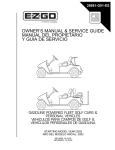
OWNER’S MANUAL & SERVICE GUIDE
MANUAL DEL PROPIETARIO
Y GUIA DE SERVICIO
Ref Fcv 1
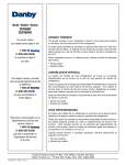
ELECTRIC POWERED FLEET GOLF CARS &
PERSONAL VEHICLES
VEHICULOS PARA CAMPOS DE GOLF &
VEHICULOS PERSONALES
STARTING MODEL YEAR 2001
AÑO DEL MODELO INICIAL: 2001
REVISED 10-10-02
REVISADO: 10-10-02
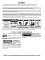
SAFETY
For any questions on material contained in this manual, contact an authorized representative for clarification.
Read and understand all labels located on the vehicle. Always replace any damaged or missing labels.
On steep hills it is possible for vehicles to coast at greater than normal speeds encountered on a flat surface. To prevent loss of vehicle control and possible serious injury, speeds should be limited to no more than the maximum speed
on level ground. See GENERAL SPECIFICATIONS. Limit speed by applying the service brake.
Catastrophic damage to the drivetrain components due to excessive speed may result from driving the vehicle above
specified speed. Damage caused by excessive speed may cause a loss of vehicle control, is costly, is considered
abuse and will not be covered under warranty.
Use extra caution when towing the vehicle(s). Do not tow a single vehicle at speeds in excess of 12 mph (19 kph). Do
not tow more than three vehicles at a time. Do not exceed 5 mph (8 kph) while towing multiple vehicles. Towing the
vehicle at above the recommended speed may result in personal injury and/or damage to the vehicle and other property. Vehicles equipped with Precision Drive System™ (PDS) must be towed with the Run-Tow/Maintenance switch,
located under the passenger seat, in the ‘Tow/Maintenance’ position.
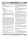
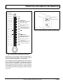
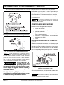
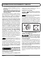
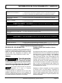
Signs similar to the ones illustrated should be used to warn of situations that could result in an unsafe condition.
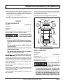
BATTERY WARNING
Battery posts,
terminals and related
accessories contain
lead and lead compounds,
chemicals known
to cause cancer and
reproductive harm.
WASH HANDS
AFTER HANDLING!
BATTERIES
CONTAIN LEAD
AND RELATED PARTS
!
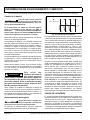
< 14˚ 25%
DO NOT
DRIVE ACROSS
SLOPES IN
EXCESS OF 14˚
WASH HANDS
AFTER HANDLING!
WARNING: Battery posts, terminals and related
accessories contain lead and lead compounds,
chemicals known to cause cancer and reproductive harm.
Be sure that this manual remains as part of the permanent service record should the vehicle be sold.
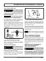
NOTES, CAUTIONS AND WARNINGS
Throughout this guide NOTE, CAUTION and WARNING
will be used.
A NOTE indicates a condition that should be
observed.
A CAUTION indicates a condition that
may result in damage to the vehicle.
Battery posts, terminals and related
accessories contain
lead and lead compounds. Wash hands after
handling.
!
!
A WARNING indicates a hazardous
condition that could
result in severe injury or death.
!
!
Observe these NOTES, CAUTIONS and WARNINGS;
be aware that servicing a vehicle requires mechanical
skill and a regard for conditions that could be hazardous.
Improper service or repair may damage the vehicle or
render it unsafe.
(NOTES, CAUTIONS AND WARNINGS CONTINUED ON INSIDE OF BACK COVER)
OWNER’S MANUAL AND
SERVICE GUIDE
ELECTRIC POWERED
FLEET GOLF CARS &
PERSONAL VEHICLES
FLEET GOLF CAR
FLEET PDS GOLF CAR
FREEDOM™
FREEDOM™ SE
FREEDOM™ LE
PDS FREEDOM™
PDS FREEDOM™ SE
PDS FREEDOM™ LE
SHUTTLE™ 2+2
E-Z-GO Division of Textron reserves the right to make design changes without obligation to make these changes on units previously sold and the information
contained in this manual is subject to change without notice.
E-Z-GO Division of Textron is not liable for errors in this manual or for incidental or consequential damages that result from the use of the material in this manual.
CUSTOMER SERVICE DEPARTMENT IN USA PHONE: 1-800-241-5855 FAX: 1-800-448-8124
OUTSIDE USA PHONE: 010-1-706-798-4311 FAX: 010-1-706-771-4609
E-Z-GO DIVISION OF TEXTRON, INC., P.O.BOX 388, AUGUSTA, GEORGIA USA 30903-0388
Owner’s Manual and Service Guide
Page i
GENERAL INFORMATION
This vehicle has been designed and manufactured in the United States of America (USA) as
a ‘World Vehicle’. The Standards and Specifications listed in the following text originate in
the USA unless otherwise indicated.
The use of non Original Equipment Manufacturer (OEM) approved parts may void the
warranty.
Overfilling batteries may void the warranty.
BATTERY PROLONGED STORAGE
All batteries will self discharge over time. The rate of self discharge varies depending on the
ambient temperature and the age and condition of the batteries.
A fully charged battery will not freeze in winter temperatures unless the temperature falls
below -75° F (-60° C).
For winter storage, the batteries must be clean, fully charged and disconnected from any
source of electrical drain. The battery charger and the controller are both sources of
electrical drain. Unplug the battery charger DC plug from the vehicle receptacle.
On PDS vehicles, disconnect the controller from the battery set by selecting the ‘TOW/
MAINTENANCE’ position on the RUN-TOW/MAINTENANCE SWITCH located under the
passenger seat.
As with all electric vehicles, the batteries must be checked and recharged as required or at a
minimum of 30 day intervals.
Page ii
Owner’s Manual and Service Guide
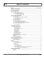
TABLE OF CONTENTS
SAFETY ................................................................................................................. Inside covers
GENERAL INFORMATION ........................................................................................................ ii
SAFETY INFORMATION ............................................................................................................ v
BEFORE INITIAL USE .............................................................................................................. 1
Fig. 1 Initial Service Chart ......................................................................................................................1
PORTABLE CHARGER INSTALLATION ............................................................................................................1
Fig. 2 Proper Charger Installation ..........................................................................................................2
Fig. 3 Charger Receptacle Location ......................................................................................................2
CONTROLS AND INDICATORS ............................................................................................... 2
KEY/LIGHT SWITCH ...........................................................................................................................................2
Fig. 4 Key/Light Switch & State of Charge Meter ..................................................................................2
DIRECTION SELECTOR .....................................................................................................................................3
Fig. 5 Direction Selector Types ..............................................................................................................3
STATE OF CHARGE METER .............................................................................................................................3
ACCELERATOR PEDAL .....................................................................................................................................3
Fig. 6 Accelerator and Brake Controls ...................................................................................................3
COMBINATION BRAKE AND PARK BRAKE PEDAL .........................................................................................3
RUN - TOW/MAINTENANCE SWITCH (PDS VEHICLES ONLY) .......................................................................3
Fig. 7 Run-Tow/Maintenance Switch .....................................................................................................4
HORN ..................................................................................................................................................................4
Fig. 8 Horn Button ..................................................................................................................................4
OPERATING THE VEHICLE ..................................................................................................... 4
PRECISION DRIVE SYSTEM™ ..........................................................................................................................5
Performance Options .....................................................................................................................................5
Fig. 9 Performance Options ...................................................................................................................5
Regenerative Braking.....................................................................................................................................6
Pedal-Up Brakng ............................................................................................................................................6
Walk-Away Feature ........................................................................................................................................6
Anti-Roll Back Feature ...................................................................................................................................6
Anti-Stall Feature ...........................................................................................................................................6
High Pedal Disable Feature ...........................................................................................................................6
Diagnostic Mode Feature ...............................................................................................................................7
STARTING AND DRIVING ..................................................................................................................................7
STARTING VEHICLE ON A HILL (Non PDS Vehicle) .........................................................................................7
COASTING ..........................................................................................................................................................7
LABELS AND PICTOGRAMS .............................................................................................................................7
SUN TOP AND WINDSHIELD .............................................................................................................................8
VEHICLE CLEANING AND CARE ............................................................................................ 8
VEHICLE CLEANING ..........................................................................................................................................8
VEHICLE CARE PRODUCTS .............................................................................................................................8
REPAIR ...................................................................................................................................... 9
LIFTING THE VEHICLE ......................................................................................................................................9
Fig. 10 Lifting the Vehicle ......................................................................................................................9
WHEELS AND TIRES .........................................................................................................................................9
Tire Repair .....................................................................................................................................................9
Wheel Installation ......................................................................................................................................... 10
Fig. 11 Wheel Installation .................................................................................................................... 10
LIGHT BULB REPLACEMENT .......................................................................................................................... 10
Fig. 12 Headlight, Turn Signal & Marker Light Bulb Replacement ...................................................... 11
Fig. 13 Tail and Brake Light Bulb Replacement .................................................................................. 11
TRANSPORTING VEHICLE .................................................................................................... 11
TOWING ............................................................................................................................................................ 11
HAULING ........................................................................................................................................................... 12
Owner’s Manual and Service Guide
Page iii
TABLE OF CONTENTS
SERVICE AND MAINTENANCE .............................................................................................. 12
SERIAL NUMBER PLATE LOCATION ............................................................................................................. 12
Early Production .......................................................................................................................................... 12
Fig. 14 Serial Number Plate Location - Early Production .................................................................... 13
Late Production ........................................................................................................................................... 13
Fig. 15 Serial Number Plate Location - Late Production ..................................................................... 13
PERIODIC SERVICE SCHEDULE .................................................................................................................. 14
Fig. 16 Periodic Service Schedule ...................................................................................................... 14
TIRE INSPECTION ........................................................................................................................................... 15
BRAKES ........................................................................................................................................................... 15
Periodic Brake Test for Mechanical Brakes................................................................................................. 15
Fig. 17 Typical Brake Performance Test ............................................................................................. 16
REAR AXLE ...................................................................................................................................................... 16
Fig. 18 Add, Check and Drain Axle Lubricant - Early Production ........................................................ 16
Fig. 19 Add, Check and Drain Axle Lubricant - Late Production ......................................................... 16
Checking the Lubricant Level ...................................................................................................................... 17
LUBRICATION .................................................................................................................................................. 17
Fig. 20 Lubrication Points - Early Production ...................................................................................... 17
Fig. 21 Lubrication Points - Late Production ....................................................................................... 17
PDS SYSTEM TEST ......................................................................................................................................... 17
HARDWARE ..................................................................................................................................................... 17
Fig. 22 Torque Specifications and Bolt Grades ................................................................................... 18
CAPACITIES AND REPLACEMENT PARTS ................................................................................................... 18
Fig. 23 Capacities and Replacement Parts ......................................................................................... 18
BATTERIES AND CHARGING ................................................................................................ 19
SAFETY ............................................................................................................................................................ 19
BATTERY ......................................................................................................................................................... 19
BATTERY MAINTENANCE .............................................................................................................................. 19
At Each Charging Cycle .............................................................................................................................. 19
Monthly ........................................................................................................................................................ 20
Electrolyte Level and Water......................................................................................................................... 20
Fig. 24 Correct Electrolyte Level ......................................................................................................... 20
Fig. 25 Water Purity Table .................................................................................................................. 20
Fig. 26 Automatic Watering Gun ......................................................................................................... 21
Battery Cleaning .......................................................................................................................................... 21
Fig. 27 Preparing Acid Neutralizing Solution ....................................................................................... 21
Battery Replacement ................................................................................................................................... 21
Fig. 28 Battery Connections ................................................................................................................ 22
Prolonged Storage....................................................................................................................................... 22
Fig. 29 Freezing Point of Electrolyte ................................................................................................... 23
BATTERY CHARGING ..................................................................................................................................... 22
AC Voltage .................................................................................................................................................. 23
TROUBLESHOOTING ...................................................................................................................................... 23
Hydrometer.................................................................................................................................................. 23
Fig. 30 Hydrometer ............................................................................................................................. 24
Using A Hydrometer .................................................................................................................................... 24
BATTERY CHARGER MAINTENANCE ........................................................................................................... 24
Fig. 31 Hydrometer Temperature Correction ...................................................................................... 25
Fig. 32 Cleaning Auxiliary Contact in Charger Plug ............................................................................ 25
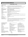
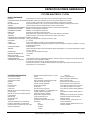
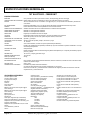
GENERAL SPECIFICATIONS .................................................................................................. 27
TXT ELECTRIC - FLEET ................................................................................................................................... 28
TXT PDS ELECTRIC - FLEET........................................................................................................................... 29
TXT ELECTRIC - FREEDOM™......................................................................................................................... 30
TXT ELECTRIC - FREEDOM™ SE ................................................................................................................... 31
TXT ELECTRIC - FREEDOM™ LE ................................................................................................................... 32
TXT PDS ELECTRIC - FREEDOM™ ................................................................................................................ 33
TXT PDS ELECTRIC - FREEDOM™ SE........................................................................................................... 34
TXT PDS ELECTRIC - FREEDOM™ LE ........................................................................................................... 35
TXT ELECTRIC - SHUTTLE 2+2....................................................................................................................... 36
Page iv
Owner’s Manual and Service Guide
TABLE OF CONTENTS
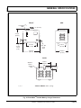
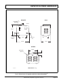
Fig. 29 Vehicle Dimensions ................................................................................................................... 37
Fig. 30 Vehicle Dimensions, Incline Specifications and Turning Clearance Diameter ..........................38
Fig. 31 PowerWise™ Portable Battery Charger Dimensions ................................................................ 39
LIMITED WARRANTIES........................................................................................................... 41
DOMESTIC WARRANTY ...................................................................................................................................42
INTERNATIONAL WARRANTY (2001) .............................................................................................................. 43
INTERNATIONAL WARRANTY (2002) .............................................................................................................. 44
INTERNATIONAL WARRANTY (2003) .............................................................................................................. 45
DECLARATION OF CONFORMITY (EUROPE ONLY)............................................................ 47
FLEET GOLF CAR (2000).................................................................................................................................. 48
FREEDOM™ GOLF CAR (2000) ....................................................................................................................... 49
FREEDOM™ HP GOLF CAR (2000) ................................................................................................................. 50
SHUTTLE 2+2 (2000)......................................................................................................................................... 51
FLEET AND FREEDOM™ GOLF CAR (2002)................................................................................................... 52
SHUTTLE 2+2 (2002)......................................................................................................................................... 53
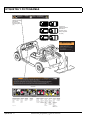
LABELS AND PICTOGRAMS .................................................................................. Appendix A
Owner’s Manual and Service Guide
Page v
TABLE OF CONTENTS
Notes:
Page vi
Owner’s Manual and Service Guide
SAFETY INFORMATION
This manual has been designed to assist in maintaining the vehicle in accordance with procedures developed by the
manufacturer. Adherence to these procedures and troubleshooting tips will ensure the best possible service from the
product. To reduce the chance of personal injury or property damage, the following must be carefully observed:
GENERAL
Many vehicles are used for a variety of tasks beyond the original intended use of the vehicle; therefore, it is impossible
to anticipate and warn against every possible combination of circumstances that may occur. No warnings can take the
place of good common sense and prudent driving practices.
Good common sense and prudent driving practices do more to prevent accidents and injury than all of the warnings
and instructions combined. The manufacturer strongly suggests that all users and maintenance personnel read this
entire manual paying particular attention to the CAUTIONS and WARNINGS contained therein.
If you have any questions regarding this vehicle, contact your closest representative or write to the address on the back
cover of this publication, Attention: Product Service Department.
TEXTRON Golf, Turf & Specialty Products reserves the right to make design changes without obligation to make these
changes on units previously sold and the information contained in this manual is subject to change without notice.
TEXTRON Golf, Turf & Specialty Products is not liable for errors in this manual or for incidental or consequential damages that result from the use of the material in this manual.
This vehicle conforms to the current applicable standard(s) for safety and performance requirements.
These vehicles are designed and manufactured for off-road use. They do not conform to Federal Motor Vehicle Safety
Standards of the United States of America (USA) and are not equipped for operation on public streets. Some communities may permit these vehicles to be operated on their streets on a limited basis and in accordance with local ordinances.
With electric powered vehicles, be sure that all electrical accessories are grounded directly to the battery (-) post.
Never use the chassis or body as a ground connection.
Refer to GENERAL SPECIFICATIONS for vehicle seating capacity.
Never modify the vehicle in any way that will alter the weight distribution of the vehicle, decrease its stability
or increase the speed beyond the factory specification. Such modifications can cause serious personal injury
or death. Modifications that increase the speed and/or weight of the vehicle will extend the stopping distance and may
reduce the stability of the vehicle. Do not make any such modifications or changes. The manufacturer prohibits and
disclaims responsibility for any such modifications or any other alteration which would adversely affect the safety of the
vehicle.
Vehicles that are capable of higher speeds must limit their speed to no more than the speed of other vehicles when
used in a golf course environment. Additionally, speed should be further moderated by the environmental conditions,
terrain and common sense.
GENERAL OPERATION
Always:
• Use the vehicle in a responsible manner and maintain the vehicle in safe operating condition.
• Read and observe all warnings and operation instruction labels affixed to the vehicle.
• Follow all safety rules established in the area where the vehicle is being operated.
Owner’s Manual and Service Guide
Page vii
SAFETY INFORMATION
• Reduce speed to compensate for poor terrain or conditions.
• Apply service brake to control speed on steep grades.
• Maintain adequate distance between vehicles.
• Reduce speed in wet areas.
• Use extreme caution when approaching sharp or blind turns.
• Use extreme caution when driving over loose terrain.
• Use extreme caution in areas where pedestrians are present.
MAINTENANCE
Always:
• Maintain the vehicle in accordance with the manufacturer’s periodic service schedule.
• Ensure that repairs are performed by those that are trained and qualified to do so.
• Follow the manufacturer’s maintenance procedures for the vehicle. Be sure to disable the vehicle before performing
any maintenance. Disabling includes removing the key from the key switch and removal of a battery wire.
• Insulate any tools used within the battery area in order to prevent sparks or battery explosion caused by shorting the
battery terminals or associated wiring. Remove the batteries or cover exposed terminals with an insulating material.
• Check the polarity of each battery terminal and be sure to rewire the batteries correctly.
• Use specified replacement parts. Never use replacement parts of lesser quality.
• Use recommended tools.
• Determine that tools and procedures not specifically recommended by the manufacturer will not compromise the
safety of personnel nor jeopardize the safe operation of the vehicle.
• Support the vehicle using wheel chocks and jack stands. Never get under a vehicle that is supported by a jack. Lift
the vehicle in accordance with the manufacturer’s instructions.
• Maintain the vehicle in an area away from exposed flame or persons who are smoking.
• Be aware that a vehicle that is not performing as designed is a potential hazard and must not be operated.
• Test drive the vehicle after any repairs or maintenance. All tests must be conducted in a safe area that is free of both
vehicular and pedestrian traffic.
• Replace damaged or missing warning, caution or information labels.
• Keep complete records of the maintenance history of the vehicle.
The manufacturer cannot anticipate all situations, therefore people attempting to maintain or repair the vehicle must
have the skill and experience to recognize and protect themselves from potential situations that could result in severe
personal injury or death and damage to the vehicle. Use extreme caution and, if unsure as to the potential for injury,
refer the repair or maintenance to a qualified mechanic.
Page viii
Owner’s Manual and Service Guide
SAFETY INFORMATION
VENTILATION
Hydrogen gas is generated in the charging cycle of batteries and is explosive in concentrations as low as 4%. Because
hydrogen gas is lighter than air, it will collect in the ceiling of buildings necessitating proper ventilation. Five air
exchanges per hour is considered the minimum requirement.
Never charge a vehicle in an area that is subject to flame or spark. Pay particular attention to natural gas or propane
water heaters and furnaces.
Always use a dedicated circuit for each battery charger. Do not permit other appliances to be plugged into the receptacle when the charger is in operation.
Chargers must be installed and operated in accordance with charger manufacturers recommendations or applicable
electrical code (whichever is higher).
Owner’s Manual and Service Guide
Page ix
SAFETY INFORMATION
Notes:
Page x
Owner’s Manual and Service Guide
SAFETY INFORMATION
Read all of manual to become thoroughly familiar with this vehicle. Pay particular attention to all Notes, Cautions and Warnings
GENERAL
The following text is provided as recommended by part II
of ASME/ANSI B56.8-1988. E-Z-GO strongly endorses
the contents of this specification.
manual without the manufacturer’s prior written authorization. Where authorized modifications have been made,
the user shall ensure that capacity, operation, warning,
and maintenance instruction plates, tags, or decals are
changed accordingly.
PART II
FOR THE USER
4.3.3 As required under paras. 4.3.1 or 4.3.2, the
manufacturer shall be contacted to secure new nameplates, warnings, or instructions which shall then be
affixed in their proper place on the carrier.
4 GENERAL SAFETY PRACTICES
4.4
4.1
Introduction
4.1.1 Like other machines, carriers can cause injury
if improperly used or maintained. Part II contains broad
safety practices applicable to carrier operations. Before
operation, the user shall establish such additional specific safety practices as may reasonably be required for
safe operation.
4.2
Stability
4.2.1
Experience has shown that this vehicle, which
complies with this standard, is stable when properly
operated and when operated in accordance with specific
safety rules and practices established to meet actual
operating terrain and conditions. However, improper
operation, faulty maintenance, or poor housekeeping
may contribute to a condition of instability and defeat the
purpose of the standard. Some of the conditions which
may affect stability are failure of the user to follow safety
practices; also, ground and floor conditions, grade,
speed, loading, the operation of the carrier with improper
loads, battery weight, dynamic and static forces, and the
judgement exercised by the carrier operator.
(a) The user shall train carrier operators to adhere
strictly to the operating instructions stated in this Standard.
(b) The user shall survey specific operating conditions
and environment, and establish and train carrier operators to comply with additional, specific safety practices.
4.3
Nameplates, Markings, Capacity, and Modifications
4.3.1 The user shall maintain in a legible condition
all nameplates, warnings, and instructions which are
supplied by the manufacturer.
4.3.2 The user shall not perform any modification or
addition which affects capacity or safe operation, or
make any change not in accordance with the owner’s
Fuel Handling and Storage
4.4.1 The user shall supervise the storage and handling of liquid fuels (when used) to be certain that it is in
accordance with appropriate paragraphs of ANSI/NFPA
505 and ANSI/NFPA 30.
4.4.2 Storage and handling of liquefied petroleum
gas fuels shall be in accordance with appropriate paragraphs of ANSI/NFPA 505 and ANSI/NFPA 58. If such
storage or handling is not in compliance with these standards, the user shall prevent the carrier from being used
until such storage and handling is in compliance with
these standards.
4.5
Changing and Charging Storage Batteries for
Electric Personnel and Burden Carriers
4.5.1 The user shall require battery changing and
charging facilities and procedures to be in accordance
with appropriate paragraphs of ANSI/NFPA 505.
4.5.2 The user shall periodically inspect facilities
and review procedures to be certain that appropriate
paragraphs of ANSI/NFPA 505, are strictly complied with,
and shall familiarize carrier operators with it.
4.6
Hazardous Locations
4.6.1 The user shall determine the hazard classification of the particular atmosphere or location in which
the carrier is to be used in accordance with ANSI/NFPA
505.
4.6.2 The user shall permit in hazardous areas only
those carriers approved and of the type required by
ANSI/NFPA 505.
4.7
Lighting for Operating Areas
4.7.1 The user, in accordance with his responsibility
to survey the environment and operating conditions, shall
determine if the carrier requires lights and, if so, shall
equip the carrier with appropriate lights in accordance
with the manufacturer’s recommendations.
Owner’s Manual and Service Guide
Page xi
SAFETY INFORMATION
Read all of manual to become thoroughly familiar with this vehicle. Pay particular attention to all Notes, Cautions and Warnings
4.8
Control of Noxious Gases and Fumes
turer;
4.8.1 When equipment powered by internal combustion engines is used in enclosed areas, the atmosphere shall be maintained within limits specified in the
American Conference of Governmental Industrial
Hygienists publication, “Threshold Limit Values for
Chemical Substances and Physical Agents in the Workroom Environment”. This shall be accomplished by ventilation provided by the user, and/or the installation, use,
and proper maintenance of emission control equipment
recommended or provided by the manufacturer of the
equipment.
(b) emphasis on safety of passengers, material loads,
carrier operator, and other employees;
4.9
(e) operational performance tests and evaluations during, and at completion of, the program.
Warning Device(s)
4.9.1 The user shall make periodic inspections of
the carrier to be certain that the sound-producing and/or
visual device(s) are maintained in good operating condition.
(c) general safety rules contained within this Standard
and the additional specific rules determined by the user
in accordance with this Standard, and why they were formulated;
(d) introduction of equipment, control locations and
functions, and explanation of how they work when used
properly and when used improperly, and surface conditions, grade, and other conditions of the environment in
which the carrier is to be operated;
5.3
Personnel and Burden Carrier Operator
Responsibility
4.9.2 The user shall determine if operating conditions require the carrier to be equipped with additional
sound-producing and/or visual devices and be responsible for providing and maintaining such devices, in accordance with the manufacturer’s recommendations.
5.3.1 Operators shall abide by the following safety
rules and practices in paras. 5.4, 5.5, 5.6, and 5.7.
5 OPERATING SAFETY RULES AND
PRACTICES
5.4.2 Riding on the carrier by persons other than the
operator is authorized only on personnel seat(s) provided
by the manufacturer. All parts of the body shall remain
within the plan view outline of the carrier.
5.1
Personnel and Burden Carrier Operator
Qualifications
5.1.1 Only persons who are trained in the proper
operation of the carrier shall be authorized to operate the
carrier. Operators shall be qualified as to visual, auditory,
physical, and mental ability to safely operate the equipment according to Section 5 and all other applicable
parts of this Standard.
5.2
Personnel and Burden Carrier Operators’
Training
5.2.1 The user shall conduct an operators’ training
program.
5.2.2 Successful completion of the operators’ training program shall be required by the user before operation of the carrier. The program shall be presented in its
entirety to all new operators and not condensed for those
claiming previous experience.
5.2.3 The user should include in the operators’ training program the following:
(a)
instructional material provided by the manufac-
Page xii
5.4
General
5.4.1 Safeguard the pedestrians at all times. Do not
drive carrier in a manner that would endanger anyone.
5.4.3 When a carrier is to be left unattended, stop
carrier, apply the parking brake, stop the engine or turn
off power, turn off the control or ignition circuit, and
remove the key if provided. Block the wheels if machine
is on an incline.
5.4.4 A carrier is considered unattended when the
operator is 25 ft. (7.6 m) or more from the carrier which
remains in his view, or whenever the operator leaves the
carrier and it is not within his view. When the operator is
dismounted and within 25 ft. (7.6 m) of the carrier still in
his view, he still must have controls neutralized, and the
parking brake(s) set to prevent movement.
5.4.5 Maintain a safe distance from the edge of
ramps and platforms.
5.4.6 Use only approved carriers in hazardous locations, as defined in the appropriate safety standards.
5.4.7 Report all accidents involving personnel,
building structures, and equipment.
5.4.8
rier.
Operators shall not add to, or modify, the car-
Owner’s Manual and Service Guide
SAFETY INFORMATION
Read all of manual to become thoroughly familiar with this vehicle. Pay particular attention to all Notes, Cautions and Warnings
5.4.9 Carriers shall not be parked or left unattended
such that they block or obstruct fire aisles, access to
stairways, or fire equipment.
5.5
Traveling
5.5.1 Observe all traffic regulations, including authorized speed limits. Under normal traffic conditions keep
to the right. Maintain a safe distance, based on speed of
travel, from a carrier or vehicle ahead; and keep the carrier under control at all times.
5.5.2 Yield the right of way to pedestrians, ambulances, fire trucks, or other carriers or vehicles in emergency situations.
5.5.3 Do not pass another carrier or vehicle traveling in the same direction at intersections, blind spots, or
at other dangerous locations.
5.5.4 Keep a clear view of the path of travel,
observe other traffic and personnel, and maintain a safe
clearance.
5.5.5 Slow down or stop, as conditions dictate, and
activate the sound-producing warning device at cross
aisles and when visibility is obstructed at other locations.
5.5.6
Ascend or descend grades slowly.
5.5.7 Avoid turning, if possible, and use extreme
caution on grades, ramps, or inclines; normally travel
straight up and down.
5.5.8 Under all travel conditions the carrier shall be
operated at a speed that will permit it to be brought to a
stop in a safe manner.
smooth, sweeping motion.
5.6
Loading
5.6.1 Handle only stable and safely arranged loads.
When handling off-center loads which cannot be centered, operate with extra caution.
5.6.2 Handle only loads within the capacity of the
carrier as specified on the nameplate.
5.6.3 Handle loads exceeding the dimensions used
to establish carrier capacity with extra caution. Stability
and maneuverability may be adversely affected.
5.7
Operator Care of Personnel and Burden
Carriers
5.7.1 At the beginning of each shift during which the
carrier will be used, the operator shall check the carrier
condition and inspect the tires, warning devices, lights,
battery(s), speed and directional controllers, brakes, and
steering mechanism. If the carrier is found to be in need
of repair, or in any way unsafe, the matter shall be
reported immediately to the designated authority and the
carrier shall not be operated until it has been restored to
safe operating condition.
5.7.2 If during operation the carrier becomes unsafe
in any way, the matter shall be reported immediately to
the designated authority, and the carrier shall not be
operated until it has been restored to safe operating condition.
5.7.3 Do not make repairs or adjustments unless
specifically authorized to do so.
5.5.9 Make starts, stops, turns, or direction reversals in a smooth manner so as not to shift the load,
endanger passengers, or overturn the carrier.
5.7.4 The engine shall be stopped and the operator
shall leave the carrier while refueling.
5.5.10 Do not indulge in dangerous activities, such as
stunt driving or horseplay.
5.7.5 Spillage of oil or fuel shall be carefully and
completely absorbed or evaporated and fuel tank cap
replaced before starting engine.
5.5.11 Slow down when approaching, or on, wet or
slippery surfaces.
5.5.12 Do not drive carrier onto any elevator unless
specifically authorized to do so. Approach elevators
slowly, and then enter squarely after the elevator car is
properly leveled. Once on the elevator, neutralize the
controls, shut off power, and set parking brakes. It is
advisable that all other personnel leave the elevator
before a carrier is allowed to enter or exit.
5.5.13 Avoid running over loose objects, potholes,
and bumps.
5.5.14 To negotiate turns, reduce speed to improve
stability, then turn hand steering wheel or tiller in a
5.7.6 Do not operate a carrier with a leak in the fuel
system or battery(s).
5.7.7 Do not use open flames for checking electrolyte level in storage battery(s) or liquid level in fuel tanks.
6 MAINTENANCE PRACTICES
6.1
Introduction
6.1.1 Carriers may become hazardous if maintenance is neglected. Therefore, maintenance facilities,
trained personnel, and procedures shall be provided.
Such facilities may be on or off the premises.
Owner’s Manual and Service Guide
Page xiii
SAFETY INFORMATION
Read all of manual to become thoroughly familiar with this vehicle. Pay particular attention to all Notes, Cautions and Warnings
6.2
Maintenance Procedures
6.2.1 Maintenance and inspection of all carriers
shall be performed in conformance with the manufacturer’s recommendations and the following practices.
(a) A scheduled preventive maintenance, lubrication,
and inspection system shall be followed.
(b) Only qualified and authorized personnel shall be
permitted to maintain, repair, adjust, and inspect carriers.
(c) Before undertaking maintenance or repair, follow
the manufacturer’s recommendations for immobilizing
the carrier.
(d) Block chassis before working underneath it.
(e) Before disconnecting any part of the engine fuel
system of a gasoline or diesel powered carrier with gravity feed fuel systems, be sure shutoff valve is closed, and
run engine until fuel system is depleted and engine stops
running.
(f) Before disconnecting any part of the engine fuel
system of LP gas powered carriers, close the LP gas cylinder valve and run the engine until fuel in the system is
depleted and the engine stops running.
(g) Operation to check performance of the carrier shall
be conducted in an authorized area where safe clearance exists.
(h) Before commencing operation of the carrier, follow
the manufacturer’s instructions and recommended procedures.
(i) Avoid fire hazards and have fire protection equipment present in the work area. Do not use an open flame
to check level or leakage of fuel, battery electrolyte, or
coolant. Do not use open pans of fuel or flammable
cleaning fluids for cleaning parts.
prevent the use of the carrier until the leak has been
eliminated.
(o) The carrier manufacturer’s capacity, operation, and
maintenance instruction plates, tags, or decals shall be
maintained in legible condition.
(p) Batteries, motors, speed and directional controllers, limit switches, protective devices, electrical conductors, and connections shall be inspected and maintained
in conformance with manufacturers recommended procedures.
(q) Carriers shall be kept in a clean condition to minimize fire hazards and facilitate detection of loose or
defective parts.
(r) Modifications and additions which affect capacity
and safe machine operation shall not be performed by
the customer or user without manufacturer’s prior written
authorization; where authorized modifications have been
made, the user shall ensure that capacity, operation,
warning, and maintenance instruction plates, tags, or
decals are changed accordingly.
(s) Care shall be taken to ensure that all replacement
parts are interchangeable with the original parts and of a
quality at least equal to that provided in the original
equipment.
END OF ASME/ANSI B56.8-1988 TEXT
(j) Properly ventilate the work area.
(k) Handle LP gas cylinders with care. Physical damage, such as dents, scrapes, or gouges, may dangerously weaken the tank and make it unsafe for use.
(l) Brakes, steering mechanisms, speed and directional control mechanisms, warning devices, lights, governors, guards, and safety devices shall be inspected
regularly and maintained in a safe operating condition.
(m)
Special carriers or devices designed and
approved for hazardous area operation shall be
inspected to ensure that maintenance preserves the original approved safe operating features.
(n) Fuel systems shall be checked for leaks and condition of parts. If a leak is found, action shall be taken to
Page xiv
Owner’s Manual and Service Guide
SAFETY INFORMATION
Read all of manual to become thoroughly familiar with this vehicle. Pay particular attention to all Notes, Cautions and Warnings
GENERAL
5.2.1. Steep Grade
The following text is provided as recommended by part II
of ANSI / NGCMA Z130.1 - 1993. E-Z-GO, as a member
of the National Golf Car Manufacturers Association
(NGCMA), strongly endorses the contents of this specification.
In areas where steep grades exist, golf car operations
should be restricted to the designated golf car pathways
where possible, and shall be identified with a suitable
warning giving the following information: “Warning, steep
grade, descend slowly with one foot on brake.”
PART II
5.2.2. Wet Areas
MAINTENANCE AND OPERATIONS
5.
GENERAL SAFETY PRACTICES
5.1.
Introduction
Like other machines, golf cars can cause injury if improperly used or maintained. This section contains broad
safety practices recommended for safe golf car operations. Before operation, the controlling party should
establish such additional specific safety practices as may
be reasonably required for safe operations.
Experience has shown that golf cars which comply with
the provisions stated in Part II of this Standard are safe
when properly operated in accordance with the safety
and operation warnings affixed to every golf car. The safe
operation is enhanced when the golf cars are operated
within a specific set of operation instructions, safety rules
and practices established to meet actual operating terrain and conditions.
The safety information contained in Part II is intended to
provide the controlling party with basic safety information
and to encourage the controlling party to implement a
golf car safety program.
It is suggested and recommended that Part II be
reprinted in the golf car manufacturer’s operation and
service manuals to encourage safe operations and practices at the controlling party’s facility.
5.2.
Safety Survey
The controlling party shall perform a safety survey periodically, and as conditions warrant to their premises, to
identify areas where golf cars should not be operated
and to identify possible hazards.
Wet grassy areas may cause a golf car to lose traction
and may affect stability. Wet areas shall be chained or
roped off to prevent golf car operations or be identified by
a suitable warning not to operate golf cars in this area
due to wet terrain.
5.2.3. Sharp
Approaches
Turns,
Blind
Corners,
Bridge
Sharp turns, blind spots, bridge approaches and other
potentially hazardous areas shall be either chained or
roped off to prevent golf car operations or identified with
a suitable warning to the operator of the nature of the
hazard and stating the proper precautions to be taken to
avoid the hazard.
5.2.4. Loose Terrain
Loose terrain may cause a golf car to lose traction and
may affect stability. Areas of loose terrain should be
repaired if possible, or chained or roped off to prevent
golf car operation or identified by a suitable warning to
operators not to operate golf cars in this area due to
loose terrain or possible hazardous conditions.
5.2.5. Golf Car/Pedestrian Interference Areas
Areas where pedestrians and golf cars interfere shall be
avoided whenever possible by rerouting the golf car traffic or the pedestrian traffic to eliminate the interference. If
elimination of the interference is not possible or is highly
impractical, signs shall be erected warning pedestrians
of the golf car traffic and golf car operators of the pedestrian traffic and to drive slowly and use extreme caution.
Owner’s Manual and Service Guide
Page xv
SAFETY INFORMATION
Read all of manual to become thoroughly familiar with this vehicle. Pay particular attention to all Notes, Cautions and Warnings
6.
MAINTENANCE
6.1. Introduction
6.1.1. Golf cars may become hazardous if maintenance
is neglected or improperly performed. Therefore maintenance facilities, trained personnel and procedures in
accordance with the manufacturer’s recommendations
should be provided by the controlling party.
6.2. Preventive Maintenance
A regularly scheduled inspection and preventive maintenance program in accordance with the manufacturer’s
recommendations should be established. Such a program will be a valuable tool in providing the golfing
patron with a safe, properly operating golf car and
thereby help to avoid accidents.
6.2.1. Personnel
Only qualified, trained and authorized personnel shall be
permitted to inspect, adjust and maintain golf cars.
6.2.4. Maintenance Procedures
All maintenance shall be performed in accordance with
the manufacturer’s recommended maintenance procedures as outlined in the manufacturer’s operation and
service manuals.
6.2.5. Maintenance Safety Procedures
All maintenance shall be performed in accordance with
the manufacturer’s recommended safety procedures as
outlined in the manufacturer’s operation and service
manuals. The following list of recommended safety procedures are general in nature and in no way supersede
the manufacturer’s specific instructions.
6.2.5.1. Follow manufacturer’s instructions for immobilizing golf car before beginning any maintenance.
6.2.2. Parts and Materials
Only manufacturer’s recommended replacement parts
and materials shall be used.
6.2.3. Ventilation
Maintenance and storage areas shall be properly ventilated to avoid fire hazards in accordance with applicable
fire codes and ordinances.
6.2.3.1. Ventilation for gasoline powered golf cars shall
be provided to remove flammable vapors, fumes and
other flammable materials. Consult applicable fire codes
for specific levels of ventilation.
6.2.3.2. Ventilation for electric powered golf cars shall
be provided to remove the accumulation of flammable
hydrogen gas emitted during the charging process. The
amount of hydrogen gas emitted depends upon a number of factors such as the condition of the batteries, the
output rate of the battery charger and the amount of time
the batteries are on charge. Hydrogen emissions are
generally considered to be in the area of 10 to 20 cubic
Page xvi
liters per car per charge. Because of the highly volatile
nature of hydrogen gas and its propensity to rise and
accumulate at the ceiling in pockets, a minimum of 5 air
changes per hour is recommended. The controlling party
shall consult applicable fire and safety codes for the specific ventilation levels required as well as the use of
explosion proof electrical apparatus.
6.2.5.2. Block chassis before working underneath golf
car.
6.2.5.3. Before disconnecting any part of the fuel system, drain the system and turn all shut off valves to the
‘OFF’ position to prevent leakage or accumulation of
flammable fuels in the work area.
6.2.5.4. Avoid fire hazards and have fire protection
equipment available.
6.2.5.5. Before performing any maintenance on an electric golf car, disable the electrical system in accordance
with the manufacturer’s instructions.
6.2.5.6. Use only properly insulated tools when working
on electrically powered golf cars or around batteries.
6.2.5.7. Brakes, steering mechanisms, warning devices,
Owner’s Manual and Service Guide
SAFETY INFORMATION
Read all of manual to become thoroughly familiar with this vehicle. Pay particular attention to all Notes, Cautions and Warnings
governors and all other safety devices shall be inspected
and maintained in a safe and proper operating condition
and shall not be modified as supplied by the manufacturer.
6.2.5.8. After each maintenance or repair the golf car
shall be driven by qualified, trained and authorized personnel to ensure proper operation and adjustment.
6.2.5.9. Driving golf car to check for proper operation
and adjustment after repair shall be performed in an area
that is free of vehicular and pedestrian traffic.
6.2.5.10. Record all maintenance performed in a maintenance record log by date, name of person performing
maintenance and type of maintenance. Controlling party
management should periodically inspect maintenance
log to ensure currency and completeness of entries.
6.2.5.11. Provide operator comment cards to assist in
identifying non-periodic maintenance needs for specific
golf cars.
6.2.6. The controlling party shall maintain in a legible
condition all nameplates, warnings and instructions
which are supplied by the manufacturer.
6.2.7. The controlling party shall not perform any modification or addition which affects capacity or safe operation, or make any change not in accordance with the
owner’s manual without the manufacturer’s prior written
authorization. Where authorized modifications have been
made, the controlling party shall ensure that capacity,
operation, warning and maintenance instruction plates,
tags or decals are changed accordingly.
6.2.8. As required under paragraphs 6.2.6 and 6.2.7 the
manufacturer shall be contacted to secure new nameplates, warnings or instructions which shall then be
affixed in their proper place on the golf car.
7. FUELS HANDLING AND STORAGE/
BATTERY CHARGING
7.1.
The controlling party shall supervise the storage
and handling of liquid fuels in accordance with applicable
fire and safety requirements.
7.2.
Storage and handling of liquefied petroleum gas
fuels shall be in accordance with American Gas Association recommendations and applicable fire safety requirements.
7.3.
The controlling party shall require battery changing and charging facilities and procedures to be in accordance with applicable ordinances or regulations (also
see paragraph 6.2.3.2).
7.4.
The controlling party shall periodically inspect
facilities and review procedures to be certain that the
procedures in paragraphs 6.2.3.2 and 7.3 are being followed.
8. OPERATING SAFETY RULES AND
PRACTICES
8.1. Operator Qualifications
8.1.1. Only authorized persons shall be allowed to operate golf cars. It is recommended that no persons be
allowed to operate golf cars except those persons who
posses a valid motor vehicle driver’s license.
8.1.2. The controlling party shall display the operation
and safety instructions as recommended by the golf car
manufacturers and the golf course safety rules in a conspicuous place near the golf car rental area or golf car
pick-up area. It is also recommended, as with all motor
vehicles, that the warning “Do not operate golf cars when
under the influence of alcohol or drugs.” be posted in a
conspicuous location.
Owner’s Manual and Service Guide
Page xvii
SAFETY INFORMATION
Read all of manual to become thoroughly familiar with this vehicle. Pay particular attention to all Notes, Cautions and Warnings
Notes:
Page xviii
Owner’s Manual and Service Guide
OPERATION AND SERVICE INFORMATION
Read all of manual to become thoroughly familiar with this vehicle. Pay particular attention to all Notes, Cautions and Warnings
Thank you for purchasing this vehicle. Before driving the
vehicle, we ask you to spend some time reading this
Owner’s Manual and Service Guide. This guide contains
the information that will assist you in maintaining this
highly reliable vehicle. Some illustrations may show
items that are optional for your vehicle. This guide covers
the operation of several vehicles; therefore, some pictorial views may not represent your vehicle. Physical differences in controls will be illustrated.
This vehicle has been designed and manufactured as a
‘World Vehicle’. Some countries have individual requirements to comply with their specifications; therefore,
some sections may not apply in your country.
Vehicle batteries must be fully charged before initial use.
Check for correct tire inflation. See GENERAL SPECIFICATIONS.
Determine and record braking distance required to stop
vehicle for future brake performance tests.
Remove the protective clear plastic, that protect the seat
bottom and back rest during shipping, before placing the
vehicle in service.
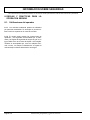
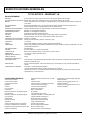
ITEM
SERVICE OPERATION
Most of the service procedures in this guide can be
accomplished using common automotive hand tools.
Contact your service representative on servicing the
vehicle in accordance with the Periodic Service Schedule.
Batteries
Charge batteries
Seats
Remove protective plastic covering
Brakes
Check operation and adjust if necessary
Service Parts Manuals and Technician’s Repair and Service Manuals are available from a local Distributor, an
authorized Branch or the Service Parts Department.
When ordering parts or requesting information for your
vehicle, provide vehicle model, serial number and manufacture date code.
Tires
Check air pressure (see SPECIFICATIONS)
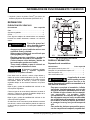
Portable
Charger
Remove from vehicle and properly mount
Establish acceptable stopping distance
Ref Isc 1
Fig. 1 Initial Service Chart
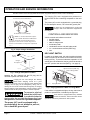
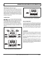
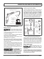
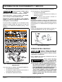
PORTABLE CHARGER INSTALLATION
BEFORE INITIAL USE
Read, understand and follow the safety label on the
instrument panel. Be sure you understand how to operate the vehicle, its equipment and how to use it safely.
Maintaining good performance depends to a large extent
on the operator.
Hydrogen gas is generated as a natural part of the
lead acid battery charging process. A 4% concentration of hydrogen gas is
explosive and could cause severe injury or death.
Charging must take place in an area that is adequately ventilated (minimum of 5 air exchanges per hour).
!
!
To reduce the chance of battery explosion
that could result in severe injury or death,
never smoke around or charge batteries in
an area that has open flame or electrical
equipment that could cause an electrical
arc.
Before a new vehicle is put into operation, the items
shown in the INITIAL SERVICE CHART must be performed (Ref Fig. 1 on page 1).
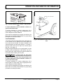
To prevent overheating that may cause
serious damage to
the charger and create the potential for fire,
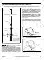
do not block or obstruct the airways. Portable chargers must be mounted on a platform above the ground or in such a manner
as to permit the maximum air flow underneath and around the charger.
!
!
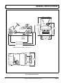
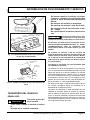
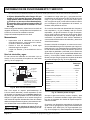
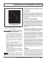
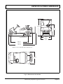
Portable chargers are shipped with the vehicle. Prior to
vehicle or charger operation, chargers must be removed
and mounted on a platform or wall above the ground to
permit maximum air flow around and underneath the
charger. If the charger is operated in an outdoor location,
rain and sun protection must be provided (Ref Fig. 2 on
page 2). A dedicated circuit is required for the charger.
Refer to the charger manual for appropriate circuit protection. The charger may remain plugged in to the AC
outlet. To charge the vehicle, refer to the instruction
labels on the charger. Insert the polarized DC plug completely into the vehicle receptacle (Ref Fig. 3 on page 2).
The charger will automatically start a few seconds after
plug insertion. The charger will automatically stop when
Owner’s Manual and Service Guide
Page 1
OPERATION AND SERVICE INFORMATION
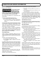
Read all of manual to become thoroughly familiar with this vehicle. Pay particular attention to all Notes, Cautions and Warnings
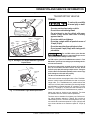
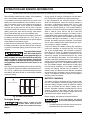
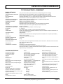
Provide Protection From Elements
The charging (DC) cord is equipped with a polarized connector which fits into a matching receptacle on the vehicle.
The power (AC) cord is equipped with a grounded plug.
Do not attempt to remove, cut or bend the ground post.
If vehicle is to be charged with a non E-Z-GO
charger, refer to the instructions supplied with
the charger.
Do Not Block Louvered Airways
NEMA 15 - 5R Grounded AC Receptacle
110 - 120 VAC. Dedicated 15 AMP Circuit
Locations outside the US and Canada: Reference
appropriate local electrical code and charger manufacturer recommendations for AC power requirements
Ref Pci 1
Fig. 2 Proper Charger Installation
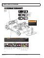
CONTROLS AND INDICATORS
Vehicle controls and indicators consist of:
• key/light switch
• direction selector
• state of charge meter
• accelerator pedal
• combination service and park brake pedal
• run - tow/maintenance switch (PDS only)
• horn
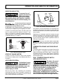
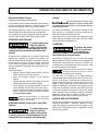
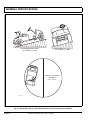
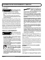
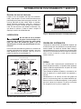
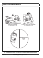
KEY/LIGHT SWITCH
Front of
Vehicle
Located on the dash panel, this switch enables the basic
electrical system of the vehicle to be turned on and off by
turning the key. To prevent inadvertent operation of the
vehicle when left unattended, the key should be turned to
the ‘OFF’ position and removed (Ref Fig. 4 on page 2).
Charger
Receptacle
Direction Selector (PDS only)
Ref Crl 1
State of Charge Meter
Fig. 3 Charger Receptacle Location
OFF
batteries are fully charged and the DC plug can be
removed to permit use of the vehicle.
Looping the DC cord through the steering
wheel when charging, serves as a good
reminder to store the cord out of the way when finished with
charging. The DC plug can be damaged by driving over or
catching the cord on the vehicle when driving away. A charging
interlock feature on the PowerWise™ charger prevents vehicle
operation while the DC plug is inserted in vehicle receptacle.
To prevent a physical
hazard that could result
in an electrical shock or
electrocution, be sure that the charger plug is not
damaged and is inserted into a grounded receptacle.
!
!
ON
Ref Kes 1
Key/Light Switch
Fig. 4 Key/Light Switch & State of Charge Meter
If the vehicle is equipped with lights, the key switch has a
position to operate them, indicated by the light icon.
If the vehicle is equipped with factory installed
custom accessories, some accessories remain
operational with the key switch in the ‘OFF’ position.
The power (AC) cord is equipped with a
grounded plug, do not attempt to pull out,
cut or bend the ground post.
Page 2
Owner’s Manual and Service Guide
OPERATION AND SERVICE INFORMATION
Read all of manual to become thoroughly familiar with this vehicle. Pay particular attention to all Notes, Cautions and Warnings
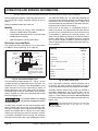
DIRECTION SELECTOR
Park
Brake
To prevent loss of
control, do not move
PDS vehicle direction selector while the vehicle is in motion.
Moving the selector will result in a sudden
slowing of the vehicle and the beeping of a
warning device.
!
!
PARK
To reduce the possibility of component
damage, the vehicle must be completely stopped before moving the direction selector.
On PDS models, if the direction selector is shifted before the
vehicle comes to a complete stop, a warning beeper will activate.
Located on the seat support panel or the dash panel, this
lever or switch permits the selection of either ‘F’ (forward), ‘R’ (reverse) or neutral (the position between forward and reverse). Vehicle should be left in neutral when
unattended (Ref Fig. 5 on page 3).
FWD
Neutral
Reverse
REV
Forward
FWD
REV
Forward
Reverse
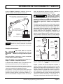
Service
Brake
Accelerator
Ref Abc 1
Fig. 6 Accelerator and Brake Controls
If key switch is ‘ON’ and park brake is set, depressing the
accelerator inadvertently will release the park brake and
will cause the vehicle to move which could cause severe
injury or death.
Depressing the accelerator pedal will release the park
brake if it is engaged. This is a feature to assure the vehicle is not driven with the park brake engaged. Depressing the accelerator pedal is not the preferred method of
releasing the park brake.
Depressing the lower section of the brake
pedal is the preferred method of releasing the
park brake to assure the longest service life of brake components.
COMBINATION BRAKE AND PARK BRAKE
PEDAL
Neutral, as shown
Ref Dsl 1
Fig. 5 Direction Selector Types
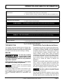
STATE OF CHARGE METER
Located in the dash, the state of charge meter indicates
the amount of usable power in the batteries (Ref Fig. 4
on page 2).
ACCELERATOR PEDAL
Unintentional move!
! ment of the accelerator pedal will
release the park brake and may cause the
vehicle to move which could result in
severe injury or death.
With the key switch ‘ON’, depressing the accelerator
pedal starts the motor. When the pedal is released, the
motor will stop (Ref Fig. 6 on page 3). To stop the vehicle
more quickly, depress the service brake.
The brake pedal incorporates a park brake feature (Ref
Fig. 6 on page 3). To engage, push down on the upper
section of the pedal until it locks in place. The park brake
will release when the service brake pedal is depressed.
Use the lower section of the brake pedal to operate the
service brake system.
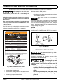
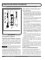
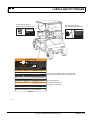
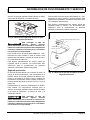
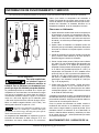
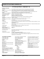
RUN - TOW/MAINTENANCE SWITCH
(PDS VEHICLES ONLY)
To reduce the possibilty of severe injury or death resulting
from loss of vehicle control, consider the
grade of the terrain the vehicle is on and set
vehicle’s park brake accordingly before
switching the Run - Tow/Maintenance
switch to the ‘Tow/Maintenance’ position.
When in the ‘Tow/Maintenance’ position, the
Anti-Roll Back and Walk-Away safety features of the PDS system no longer function.
!
Owner’s Manual and Service Guide
!
Page 3
OPERATION AND SERVICE INFORMATION
Read all of manual to become thoroughly familiar with this vehicle. Pay particular attention to all Notes, Cautions and Warnings
Before attempting to tow vehicle, move
the Run-Tow/Maintenance switch to the
‘Tow/Maintenance’ position. Failure to do so will damage the
controller or motor.
With the switch in ‘RUN’ position:
• the controller is activated
• the electronic braking system and warning beeper
features are activated
Before disconnecting or connecting a battery, or any other wiring, move the Run-Tow/Maintenance switch to the ‘Tow/Maintenance’ position.
PDS vehicles operate only in the ’RUN’ position.
After connecting a battery, or any other wiring, wait a minimum
of 30 seconds before moving the Run-Tow/Maintenance switch
to the ‘Run’ position.
The PDS vehicle is equipped with a two position switch
located under the passenger side of the seat on the controller environmental cover (Ref Fig. 7 on page 4).
The PDS is a low power consumption unit but it will drain
the vehicle batteries over a period of time. If the vehicle
is to be stored for a prolonged period of time, the PDS
should be disconnected from the batteries. See ‘Prolonged Storage’ on page 22.
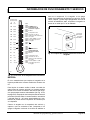
HORN
The horn is operated by pushing the horn button located on
the floor to the left of the brake pedal (Ref Fig. 8 on page 4).
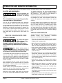
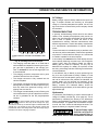
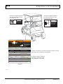
73093-G01
WARNING
■ Tampering with or unauthorized modification of this unit
TOWING
Always select 'TOW/MAINTENANCE'
Horn
by non E-Z-GO personnel could result in serious personal
injury, will void the warranty and result in permanent
damage to the vehicle
TOW
MAINTENANCE
■
position before towing
Possibility of electrical arc or battery
explosion. Before removing/connecting
batteries or electrical components, turn
switch to 'TOW MAINTENANCE' position
H
RUN
PARK
ORN
■ To disable electrical system, place switch in 'TOW/ MAINTENANCE' position and remove battery wire
■ After reconnecting batteries, allow a minimum of 30 seconds before selecting 'RUN' position
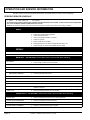
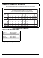
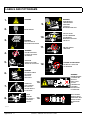
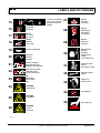
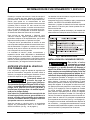
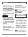
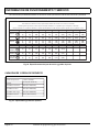
THE FOLLOWING CODES REQUIRE THAT THE REAR WHEELS BE RAISED BEFORE PERFORMING TESTS
Beep Fault
Symptoms
Correction Required
1-1
Controller Failure
Vehicle will not run
Check motor wiring & motor Ω. Replace controller
1-2
Throttle fault
Solenoid clicks, will not run
Replace/adjust pedal box, harness
1-4
2-4
Vehicle will not run
Vehicle will not run
3-1
High pedal disable
Solenoid coil failure
or disconnected
Solenoid driver fail
Release pedal/check pedal box, linkage & switch
Check coil connections/wiring,
replace solenoid if required
Check coil wiring for shorts, replace controller
3-3
3-4
Solenoid did not close
Field winding open
Vehicle will not run
Solenoid clicks, will not run
Vehicle will not run
Ref Hor 1
Check all solenoid wiring, replace solenoid if required
Check motor & controller field connections,
replace power harness or motor if required
4-1
Armature open
Solenoid clicks, will not run Check motor & controller armature connections,
replace power harness or motor if required
4-3
Solenoid drop out
Vehicle stops
Check solenoid/wiring, replace if required
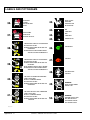
THE FOLLOWING CODES REQUIRE THAT THE VEHICLE BE OPERATED UNDER LOAD WHILE PERFORMING TESTS
Beep
Fault
Symptoms
Correction Required
Fig. 8 Horn Button
1-3
Speed sensor fault
2-1
2-2
Low battery voltage
High battery voltage
Vehicle runs slowly
Check speed sensor connections & magnet/torque,
replace speed sensor if required
Vehicle performance reduced Charge batteries/replace bad batteries
Regen performance reduced Check that battery voltage is less than 48 VDC
OPERATING THE VEHICLE
2-3
3-2
Thermal cutback
Solenoid welded
Vehicle performance reduced Allow controller to cool, check heat sink bolt torque
Vehicle runs slowly
Check auxiliary power. Replace solenoid
4-2
Motor stalled
Vehicle stopped
Improper use of the vehicle or the lack
of proper maintenance may result in
damage or decreased performance.
Remove mechanical blockage
To enter diagnostic mode ◆ Turn key switch to 'OFF' ◆ Move 'RUN/TOW MAINTENANCE' switch to 'RUN'. ◆ Move direction
selector switch from neutral position to 'REV' position five (5) times ◆ After a confirming beep(s) sounds, the diagnostic fault
code will sound when a fault is detected. To exit diagnostic mode: Select 'TOW MAINTENANCE' position.
Read and understand the following warnings before
attempting to operate the vehicle.
Controller
Environmental
Cover
Ref Rtm 1
Fig. 7 Run-Tow/Maintenance Switch
With the switch in ‘TOW/MAINTENANCE’ position:
• the controller is deactivated
• the electronic braking system is deactivated which
allows the vehicle to be towed or roll freely
• the warning beeper is deactivated
Page 4
To reduce the possibility
of severe injury or death
resulting from loss of
vehicle control, the following warnings must be
observed:
When driving vehicle, consider the terrain, traffic
conditions and the environmental factors which
effect the terrain and the ability to control the
vehicle.
Use extra care and reduced speed when driving
on poor surfaces, such as loose dirt, wet grass,
gravel, etc.
!
Owner’s Manual and Service Guide
!
OPERATION AND SERVICE INFORMATION
Read all of manual to become thoroughly familiar with this vehicle. Pay particular attention to all Notes, Cautions and Warnings
Stay in designated areas and avoid extremely
rough terrain.
Maintain a safe speed when driving down hill. Use
service brake to control speed when traveling
down an incline. A sudden stop or change of
direction may result in loss of control.
To prevent loss of control, do not move the direction selector of a PDS vehicle while the vehicle is
in motion. Moving the selector will result in a sudden slowing of the vehicle and the beeping of a
warning device.
Slow down before and during turns. All turns
should be made at reduced speed.
Never drive vehicle up, down, or across an incline
that exceeds 14° (25% grade).
To reduce the possibility
!
! of severe injury or death
resulting from improper
vehicle operation, the following warnings must be
observed:
Refer to GENERAL SPECIFICATIONS for seating
capacity.
Depressing accelerator pedal will release foot
operated park brake and may cause inadvertent
vehicle movement. Turn the key to the ‘OFF’ position whenever the vehicle is parked.
To prevent inadvertent movement when the vehicle is to be left unattended, engage the park
brake, move direction selector to forward position, turn key to ‘OFF’ position and remove key.
Make sure that the direction selector is in correct
position before attempting to start the vehicle.
Always bring the vehicle to a complete stop
before shifting the direction selector.
Do not take vehicle out of ‘gear’ while in motion
(coast).
Check the area behind the vehicle before operating in reverse.
All occupants must be seated. Keep entire body
inside vehicle and hold on while vehicle is in
motion.
PRECISION DRIVE SYSTEM™
Precision Drive System™ (PDS) vehicles are operated in
one of four modes or “performance options”. All options
have standard features that control, protect and diagnose
the vehicle.
PDS vehicles operate only when the Run Tow/Maintenance switch is in the ’RUN’ position. See ‘RUN - TOW/MAINTENANCE SWITCH (PDS VEHICLES ONLY)’ on page 3.
Performance Options
The options are defined as follows:
Performance Option
Top Speed
Pedal-Up
Braking Strength
1. All Terrain
13 - 13.5 mph
(21 - 22 kph)
None
2. Steep Hill
13 - 13.5 mph
(21 - 22 kph)
Heavy
3. Mild Hill
14 - 14.5 mph
(22.5 - 23 kph)
Mild
4. Freedom
17 - 19 mph
(27 - 30.5 kph)
None
Fig. 9 Performance Options
1. The All-Terrain performance option: The vehicle’s top
speed is sensed and regulated directly by the controller.
2. The Steep Hill performance option: This option
includes all of the driving features and top speed of
All-Terrain plus pedal-up braking. This is the strongest of the two pedal-up braking options.
3. The Mild Hill performance option: This option includes
all of the driving features of the Steep Hill option,
except the pedal-up braking feel is milder and the top
speed is slightly higher.
4. The Freedom performance option: This option
includes all of the driving features of the All-Terrain
option except that the vehicle’s top speed is the highest available. This option is not offered on fleet golf
cars.
The Freedom option is not available for fleet
golf cars.
The vehicle performance option can be determined by
placing the vehicle in diagnostic mode. See Technician’s
Repair and Service Manual. The number of beeps heard
immediately after entering diagnostic mode corresponds
to the above option numbers.
Owner’s Manual and Service Guide
Page 5
OPERATION AND SERVICE INFORMATION
Read all of manual to become thoroughly familiar with this vehicle. Pay particular attention to all Notes, Cautions and Warnings
Regenerative Braking
To prevent the possibility of loss of
control that could
cause severe injury or death, use service
brake to control speed. The PDS system is
not a substitute for the service brake.
!
!
PDS models are equipped with a regenerative motor
control system.
a) the vehicle has been stopped for more than 1.5
seconds
b) the accelerator pedal has been released for more
than one second
c) the vehicle begins to roll above 2 mph (3 kph)
the electronic braking will limit speed to approximately 2
mph (3 kph) and the warning beeper will sound. When
the accelerator pedal is depressed, the electronic braking and warning beeper will be overridden and normal
vehicle operation resumes. Any unusual situation sensed
by the PDS system will cause a similar response. The
system functions in all key switch positions.
Example: If all of the following events occur...
a) the vehicle is being driven down a slope
b) the vehicle attempts to exceed the specified top
speed with the accelerator pedal depressed or
released
Anti-Roll Back Feature
the regenerative braking will limit the speed of the vehicle
to the specified top speed (the warning beeper will not
sound). When the regenerative braking system is activated by this sequence of events, the motor generates
power which is returned to the batteries.
Anti-Stall Feature
If the operator attempts to override the regenerative
braking feature by moving the direction selector or key
switch to another position, the warning beeper will sound
and the vehicle will brake rapidly until it reaches the
speed of approximately 2 mph (3 kph).
Pedal-Up Brakng
Pedal-up braking is regenerative braking that occurs
when the accelerator pedal is released while the vehicle
is moving between 8 mph (13 kph) and the vehicle’s top
speed.
Example: If all of the following events occur...
a) the vehicle is being driven down a slope
b) the accelerator pedal is released for more than
one second
the pedal-up braking will slow the vehicle (the warning
beeper will not sound) until either the vehicle speed is
reduced to 8 mph (13 kph), at which it freely coasts
between 8 and 3 mph (5 kph), or the accelerator pedal is
applied. When pedal-up braking system is activated by
this sequence of events, the motor generates power
which is returned to the batteries.
Walk-Away Feature
Walk-Away limits vehicle movement without driver input,
slowing the vehicle to 2 mph (3 kph) and sounding an
audible alarm (reverse beeper).
Anti-Roll Back, like Walk-Away, limits backward motion of
the vehicle down an incline to less than 2 mph (3 kph).
See ‘Walk-Away Feature’ above.
Anti-Stall protection prevents motor damage from stalling
the vehicle against an object or on a hill.
Example: If all of the following events occur...
a) the system senses that the accelerator pedal is
depressed (power applied to motor)
b) the motor is stalled long enough that any more
time may cause motor damage
the PDS system will momentarily interrupt power to the
motor. This brief interruption will permit the car to roll
backwards slightly before again stopping in the stalled
condition. This process will repeat itself periodically until
the car is moved from the stalled condition.
Example: If all of the following events occur...
a) the system senses that the accelerator pedal is
depressed (power applied to motor)
b) the brake is engaged so as to prevent vehicle
motion
the PDS system will sense a stalled motor condition and
remove power from the motor. When the brake pedal is
released, the car will roll backwards slightly before power
is returned to the motor.
High Pedal Disable Feature
High pedal disable prevents undesired acceleration if the
direction selector lever is changed, or the key is turned
on while the accelerator is depressed.
Example: If all of the following events occur...
Page 6
Owner’s Manual and Service Guide
OPERATION AND SERVICE INFORMATION
Read all of manual to become thoroughly familiar with this vehicle. Pay particular attention to all Notes, Cautions and Warnings
Diagnostic Mode Feature
started.
Diagnostic mode eases troubleshooting.
In the unlikely event of certain electrical system failures,
the PDS controller will default to a mode that will permit
the vehicle to operate, but at a very reduced speed.
This feature allows the vehicle to be driven back to its
storage facility where the problem can be diagnosed.
The controller can be put in diagnostic mode by the technician and the controller will report the failure mode.
STARTING AND DRIVING
To reduce the possibility of roll-back
which could result
in severe injury or vehicle damage, do not
release the service brake until motor has
started.
!
!
All vehicles are equipped with an interlock system that
disables the controller and prevents the vehicle from
being operated while the charger is connected. The interlock functions even if the DC plug is not fully connected
in the vehicle receptacle. Remove charger plug from
vehicle receptacle and properly store cable prior to moving vehicle.
To operate vehicle:
• Apply the service brake, place the key in the key
switch and turn it to the ‘ON’ position.
• Move the direction selector to the direction
desired.
• Release the park brake by depressing the service
brake pedal until the park brake releases.
• Slowly depress the accelerator pedal to start the
motor. Release service brake when motor starts.
• When the accelerator pedal is released, the motor
stops. To stop the vehicle more quickly, depress
the service brake pedal.
When the direction selector is in the reverse
position, a warning signal will sound to indicate
that the vehicle is ready to run in reverse.
STARTING VEHICLE ON A HILL (Non PDS
Vehicle)
To reduce the possibility of roll-back
which could result
in severe injury or vehicle damage, do not
release the service brake until motor has
!
!
Do not hold vehicle on hill by using
accelerator and motor. Leaving motor
in a stalled condition for more than 3 - 4 seconds will cause permanent damage to motor.
To reduce the possibility of permanent damage to the
drive system, it is important to prevent excessive rollback when starting the vehicle on a hill.
Place left foot on service brake and release the park
brake. Depress accelerator with right foot and release
the service brake by lifting left foot.
COASTING
To reduce the possibility of severe injury or death from
coasting at above recommended speeds,
limit speed with service brake.
!
!
Uncontrolled coasting does not occur with PDS model
vehicles because the PDS controls the top speed of the
vehicle while moving down hill. However, the PDS is not
a substitute for the service brake which should be used
to control the speed of the vehicle.
Some PDS models are equipped with a feature
(pedal-up braking) which slows the vehicle’s
speed when the accelerator pedal is released.
On steep hills, it is possible for non-PDS vehicles to
coast at faster than normal speeds that may be encountered on a flat surface. To prevent loss of vehicle control,
speeds should be limited to no more than the maximum
speed on level ground (see vehicle specification). Limit
speed by releasing the accelerator and applying service
brake. Severe damage to the drive train components due
to excessive speed may result from driving the vehicle
above specified speed. Damage caused by excessive
speed may cause a loss of control, is costly, is considered abuse and will not be covered under warranty.
LABELS AND PICTOGRAMS
Vehicles may be labeled with pictograms as a method of
conveying information or warnings. Appendix A illustrates and explains pictograms that may appear on the
vehicle. Not all pictograms shown in Appendix A will be
found on your vehicle.
Owner’s Manual and Service Guide
Page 7
OPERATION AND SERVICE INFORMATION
Read all of manual to become thoroughly familiar with this vehicle. Pay particular attention to all Notes, Cautions and Warnings
SUN TOP AND WINDSHIELD
!
!
The sun top does not
provide protection from
roll over or falling
objects.
The windshield does not provide protection
from tree limbs or flying objects.
The sun top and windshield provide some protection
from the elements; however, they will not keep the operator and passenger dry in a downpour. This vehicle is not
equipped with seat belts and the sun top has not been
designed to provide roll over protection. In addition, the
sun top does not protect against falling objects nor does
the windshield protect against flying objects and tree
limbs. Keep arms and legs inside of vehicle while it is
moving.
VEHICLE CLEANING AND CARE
VEHICLE CLEANING
To reduce the possi!
! bility of severe injury or vehicle
damage, read and understand all instructions supplied by manufacturer of pressure
washer.
When pressure washing exterior of
vehicle, do not use pressure in excess
of 700 psi. To reduce the possibility of cosmetic damage, do not
use any abrasive or reactive solvents to clean plastic parts.
It is important that proper techniques and cleaning materials be used. Using excessive water pressure may
cause severe injury to operator or bystander, damage to
seals, plastics, seat material, body finish or electrical system. Do not use pressure in excess of 700 psi to wash
exterior of vehicle.
Clean windshield with lots of water and a clean cloth.
Minor scratches may be removed using a commercial
plastic polish or Plexus® plastic cleaner available from
the service parts department.
Normal cleaning of vinyl seats and plastic or rubber trim
requires the use of a mild soap solution applied with a
sponge or soft brush and wipe with a damp cloth.
Removal of oil, tar, asphalt, shoe polish, etc. will require
the use of a commercially available vinyl/rubber cleaner.
The painted surfaces of the vehicle provide attractive
appearance and durable protection. Frequent washing
with lukewarm or cold water and mild detergent is
required to preserve the painted surfaces.
Occasional cleaning and waxing with non-abrasive products designed for ‘clear coat’ automotive finishes will
enhance the appearance and durability of the painted
surfaces.
Corrosive materials used as fertilizers or for dust control
can collect on the underbody of the vehicle. These materials will cause corrosion of underbody parts unless
flushed occasionally with plain water. Thoroughly clean
any areas where mud or other debris can collect. Sediment packed in closed areas should be loosened to ease
it’s removal, taking care not to chip or otherwise damage
paint.
VEHICLE CARE PRODUCTS
To help maintain the vehicle there are several products
available through local Distributors, authorized
Branches, or the Service Parts Department.
• Touch-up paint specially formulated to match vehicle
colors for use on both metal and molded plastic bodies.
(P/N 28140-G** and 28432-G**)
• Battery Protectant formulated to form a long-term, flexible, non-tacky, dry coating that will not crack, peel or
flake over a wide temperature range. (P/N 75500-G01)
• White Lithium Grease designed to provide lubrication
protection in areas where staining or discoloring is a
problem, or in areas of extreme temperature ranges.
(P/N 75502-G01)
• Penetrant/Lubricant, a 4-in-1 product that penetrates
seized parts, lubricates leaving a light lubricating film,
reduces corrosion by adhering to wet or dry surfaces
and displaces moisture, sealing against future moisture
return. (P/N 75503-G01)
• Multi-purpose Cleaner and Degreaser that contains
natural, environmentally safe solvents. (P/N 75504G01)
• Multi-purpose Hand Cleaner is an industrial strength
cleaner containing no harsh solvents, yet gently lifts
grease off hands. May be used with or without water.
(P/N 75505-G01)
• Battery Cleaner that neutralizes battery acids and dissolves terminal corrosion and can be rinsed with water.
(P/N 75506-G01)
• Biodegradable Cleaner that breaks down grease to be
easily wiped or rinsed away. (P/N 75507-G01)
Page 8
Owner’s Manual and Service Guide
OPERATION AND SERVICE INFORMATION
Read all of manual to become thoroughly familiar with this vehicle. Pay particular attention to all Notes, Cautions and Warnings
• Multi-purpose Value Pack sampler includes 4 ounce
(118 ml) aerosol cans of Battery Protector, Penetrant/
Lubricant, White Lithium Grease, and Carburetor and
Choke Cleaner. (P/N 75508-G01)
If only the front or rear of the vehicle is to be raised, place
the chocks in front and behind each wheel not being
raised to stabilize the vehicle.
Lower the vehicle by reversing the lifting sequence.
• Plexus® plastic cleaner and polish removes minor
scratches from windshield. (P/N 28433-G**)
Center of
Front Axle
REPAIR
LIFTING THE VEHICLE
Tool List
Qty. Required
Floor jack .................................................................... 1
Jack stands ................................................................. 4
Chocks ........................................................................ 4
Some servicing operations may require the front wheels,
the rear wheels, or the entire vehicle be raised.
!
!
Flat Portion
of Frame
To reduce the possibility
of severe injury or death
from a vehicle falling
from a jack:
Be sure the vehicle is on a firm and level surface.
Never get under a vehicle while it is supported by
a jack.
Use jack stands and test the stability of the vehicle on the stands.
Always place chocks in front and behind the
wheels not being raised.
Use extreme care since the vehicle is extremely
unstable during the lifting process.
When lifting vehicle, position jacks and
jack stands at the areas indicated only.
To raise the entire vehicle, install chocks in front and
behind each front wheel (Ref Fig. 10 on page 9). Center
the jack under the rear frame crossmember. Raise the
vehicle enough to place a jack stand under the outer
ends of the rear axle.
Lower the jack and test the stability of the vehicle on the
two jack stands.
Place the jack at the center of the front axle. Raise the
vehicle enough to place jack stands under the frame
crossmember as indicated.
Lower the jack and test the stability of the vehicle on all
four jack stands.
Outside End
of Rear Axle
Ref Liv 1
View from Underside of Vehicle
Fig. 10 Lifting the Vehicle
WHEELS AND TIRES
Tire Repair
Tool List
Qty. Required
Lug wrench, 3/4" ......................................................... 1
Impact socket, 3/4", 1/2" drive..................................... 1
Impact wrench, 1/2" drive ............................................ 1
Torque wrench, 1/2" drive............................................ 1
A ti r e e x p l o s io n c a n
cause severe injury or
death. Never exceed
inflation pressure rating on tire sidewall.
To reduce the possibility of tire explosion, pressurize tire with small amount of air applied intermittently to seat beads. Due to the low volume of
the small tires, overinflation can occur in seconds. Never exceed the tire manufacturer’s recommendation when seating a bead. Protect face
!
Owner’s Manual and Service Guide
!
Page 9
OPERATION AND SERVICE INFORMATION
Read all of manual to become thoroughly familiar with this vehicle. Pay particular attention to all Notes, Cautions and Warnings
and eyes from escaping air when removing valve
core.
To reduce the possibility of severe injury caused
by a broken socket when removing wheels, use
only sockets designed for impact wrench use.
Use caution when inflating tires. Overinflation
could cause the tire to separate from the wheel or
cause the tire to explode, either of which could
cause severe injury.
Use caution when inflating tires. Due to the low volume of
the small tires, overinflation can occur in seconds. Overinflation could cause the tire to separate from the wheel
or cause the tire to explode.
Tire inflation should be determined by the condition of the
terrain. See GENERAL SPECIFICATIONS section for
recommended tire inflation pressure. For outdoor applications with major use on grassy areas, the following
should be considered. On hard turf, it is desirable to have
a slightly higher inflation pressure. On very soft turf, a
lower pressure reduces the possibility of tires cutting into
the turf. For vehicles being used on paved or hard surfaces, tire inflation pressure should be in the higher
allowable range, but under no condition should inflation
pressure be higher than recommended on tire sidewall.
All four tires should have the same pressure for optimum handling characteristics. Be sure to install the valve
dust cap after checking or inflating.
The vehicle is fitted with low pressure tubeless tires
mounted on one piece rims; therefore, the most cost
effective way to repair a puncture in the tread is to use a
commercial tire plug.
Tire plug tools and plugs are available at most
automotive parts outlets and have the advantage of not requiring the tire be removed from the wheel.
If the tire is flat, remove the wheel and inflate the tire to
the maximum recommended pressure for the tire.
Immerse the tire in water to locate the leak and mark with
chalk. Insert tire plug in accordance with manufacturer’s
instructions.
To reduce the possibility of severe injury, be sure
mounting/demounting machine is anchored
to floor. Wear OSHA approved safety equipment when mounting/demounting tires.
!
Page 10
!
If the tire is to be removed or mounted, the tire changing
machine manufacturer’s recommendations must be followed in order to reduce possibility of severe injury.
Wheel Installation
To reduce the possibility of component
damage, do not tighten lug nuts to more
than 85 ft. lbs. (115 Nm) torque.
It is important to follow the ‘cross sequence’
pattern when installing lug nuts. This will
assure even seating of the wheel against the hub.
With the valve stem to the outside, mount the wheel onto
the hub with lug nuts. Finger tighten lug nuts in a ‘cross
sequence’ pattern (Ref Fig. 11 on page 10). Tighten lug
nuts to 50 - 85 ft. lbs. (70 - 115 Nm) torque in 20 ft. lbs.
(30 Nm) increments following the ‘cross sequence’ pattern.
'Cross Sequence'
3
1
Tire style
may vary
4
2
Ref Whi 1
Fig. 11 Wheel Installation
LIGHT BULB REPLACEMENT
To reduce the possibility of premature
bulb failure, do not touch new bulbs
with bare fingers. Use clean, dry tissue or paper towel to handle
the glass portion of the bulb.
For vehicles equipped with lights mounted below cowl,
locate bulb socket on backside of light bar (Ref Fig. 12
on page 11) and turn bulb socket a quarter turn counterclockwise to unlock and pull out bulb. Insert new bulb
(Ref. Capacities and Replacement Parts on page 18) and
rotate socket a quarter turn clockwise to secure.
To replace the tail and brake light bulb, remove hardware
securing lens and remove lens (Ref Fig. 13 on page 11).
Install replacement bulb (Ref. Capacities and Replacement Parts on page 18).
Owner’s Manual and Service Guide
OPERATION AND SERVICE INFORMATION
Read all of manual to become thoroughly familiar with this vehicle. Pay particular attention to all Notes, Cautions and Warnings
TRANSPORTING VEHICLE
TOWING
!
Marker
Light
Turn
Signal
Light
Marker
Light
Turn Signal
Light
Headlights
R G
Y R
!
To reduce the possibility
of severe injury or death:
Use extra caution when towing a vehicle.
Do not ride on vehicle being towed.
Do not attempt to tow the vehicle with ropes,
chains or any device other than a factory
approved tow bar.
Do not tow vehicle on highways.
Do not tow a single vehicle at speeds in excess of
12 mph (19 kph).
Do not tow more than three vehicles at a time.
Do not exceed 5 mph (8 kph) while towing multiple vehicles.
For non-PDS vehicles, place direction
selector in neutral position prior to towing to prevent possible damage to electric motor.
Ref Hdr 1
Fig. 12 Headlight, Turn Signal & Marker Light Bulb
Replacement
Rear
Fender
Tail Light
Lens
For PDS vehicles, place Run-Tow/Maintenance switch in ‘Tow/
Maintenance’ position prior to towing to prevent damage to electric motor and controller.
Do not tow a single vehicle at speeds in excess of 12 mph (19
kph). Do not tow more than three vehicles at a time. Do not
exceed 5 mph (8 kph) while towing multiple vehicles. Towing the
vehicle at above recommended speed may result in severe injury
and/or damage to vehicle and other property.
Tow bars are not intended for road use.
Ref Tlr 1
Tail Light
Bulb
Fig. 13 Tail and Brake Light Bulb Replacement
PDS model vehicles are equipped with a ‘Run-Tow/Maintenance’ switch located underneath the seat on the passenger side. The ‘Tow/Maintenance’ position allows the
vehicle to roll freely without activating the warning beeper
and eliminating potential damage to controller or motor
(Ref Fig. 7 on page 4). Check to see that vehicles to be
towed are switched to the ‘Tow/Maintenance’ position.
Never use ropes or chains to tow vehicle(s). Tow bars
are available from the Service Parts Department.
Tow bars are not intended for highway use. Before towing, place direction selector in neutral. Do not ride on
vehicle being towed. Tow bars are designed to tow only
one vehicle at a maximum speed of 12 mph (19 kph) and
up to three vehicles at a maximum speed of 5 mph (8
kph).
Owner’s Manual and Service Guide
Page 11
OPERATION AND SERVICE INFORMATION
Read all of manual to become thoroughly familiar with this vehicle. Pay particular attention to all Notes, Cautions and Warnings
HAULING
!
!
To reduce the possibility
of severe injury or death
while transporting vehi-
cle:
Secure the vehicle and contents.
Never ride on vehicle being transported.
Always remove windshield before transporting.
Maximum speed with sun top installed is 50 mph
(80 kph).
If the vehicle is to be transported at highway speeds, the
sun top must be removed and the seat bottom secured.
When transporting vehicle below highway speeds, check
for tightness of hardware and cracks in sun top at mounting points. Always remove windshield when transporting.
Always check that the vehicle and contents are adequately secured before transporting. The rated capacity
of the trailer or truck must exceed the weight of the vehicle (see GENERAL SPECIFICATIONS for vehicle
weight) and load plus 1000 lbs. (454 kg). Lock the park
brake and secure the vehicle using ratchet tie downs.
SERVICE AND MAINTENANCE
!
!
To reduce the possibility
of severe injury or death
from improper servicing
techniques:
Do not attempt any type of servicing operations
before reading and understanding all notes, cautions and warnings in this manual.
Any servicing requiring adjustments to be made
to the powertrain while the motor is running must
be made with both drive wheels raised and vehicle properly supported on jack stands.
To reduce the possibility of motor damage, never
operate vehicle at full throttle for more than 4 - 5
seconds while vehicle is in a ‘no load’ condition.
Wear eye protection when working on
the vehicle. Use extra care when working around batteries, or using solvents or compressed air.
To reduce the possibility of causing an electrical
arc, which could result in a battery explosion, turn
off all electrical loads from the battery before
removing battery wires.
Page 12
Wrap wrenches with vinyl
tape to reduce the possibility
of a dropped wrench ‘shorting out’ a battery, which could result in an explosion.
Reduce the possibility of accidental starting by
removing and grounding spark plug wires and
disconnecting battery at negative terminal before
servicing.
The electrolyte in a battery is an acid solution
which can cause severe burns to the skin and
eyes. Treat all electrolyte spills to the body and
eyes with extended flushing with clear water.
Contact a physician immediately.
Any electrolyte spills should be neutralized with a
solution of 2 teaspoons (10 ml) sodium bicarbonate (baking soda) dissolved in 1 quart (1 liters) of
water and flushed with water.
Aerosol containers of battery terminal protectant
must be used with extreme care. Insulate metal
container to reduce the possibility of can contacting battery terminals which could result in an
explosion.
It is in the best interest of both vehicle owner and service
technician, to carefully follow the procedures recommended in this manual. Preventative maintenance,
applied at recommended intervals, is the best guarantee
for keeping the vehicle both dependable and economical.
This vehicle will give years of satisfactory service, providing it receives regular maintenance. Refer to the Periodic
Service Schedule for appropriate service intervals (Ref
Fig. 16 on page 14). Refer to Lubrication Points for
appropriate lubrication locations (Ref Fig. 21 on page
17).
SERIAL NUMBER PLATE LOCATION
Early Production
The serial number and manufacture date code are
located on a plate on the passenger side of the dash
housing of the vehicle (Ref Fig. 14 on page 13).
Design changes take place on an ongoing basis. In order
to obtain correct components for the vehicle, the manufacture date code, serial number and vehicle model must
be provided when ordering service parts.
To prolong vehicle life, some maintenance items must be serviced more frequently on vehicles used under severe driving conditions such
Owner’s Manual and Service Guide
OPERATION AND SERVICE INFORMATION
Read all of manual to become thoroughly familiar with this vehicle. Pay particular attention to all Notes, Cautions and Warnings
OFF
ON
Lift Flap on Access Panel
Ref Spl 1
Serial Number
Labels
Fig. 14 Serial Number Plate Location - Early Production
as extreme temperatures, extreme dust/debris conditions, frequent use with maximum load.
To access powertrain for routine maintenance, lift or
remove seat. For major repair, refer to appropriate Technician’s Repair and Service Manual.
Some service procedures may require the vehicle to be
lifted. Refer to LIFTING THE VEHICLE for proper lifting
procedure and safety information.
Late Production
Two serial number and manufacture date code plates are
on the vehicle. One is placed on the body below the
front, driver side of the seat. The other is located on the
chassis between the seat back supports. To access it,
raise the seat and lift up the flap on the access panel
(Ref Fig. 15 on page 13).
Ref Spl 3
Fig. 15 Serial Number Plate Location - Late Production
Design changes take place on an ongoing basis. In order
to obtain correct components for the vehicle, the manufacture date code, serial number and vehicle model must
be provided when ordering service parts.
To prolong vehicle life, some maintenance items must be serviced more frequently on vehicles used under severe driving conditions such
as extreme temperatures, extreme dust/debris conditions, frequent use with maximum load.
To access powertrain for routine maintenance, lift or
remove seat. For major repair, refer to appropriate Technician’s Repair and Service Manual.
Some service procedures may require the vehicle to be
lifted. Refer to LIFTING THE VEHICLE for proper lifting
procedure and safety information.
Owner’s Manual and Service Guide
Page 13
OPERATION AND SERVICE INFORMATION
Read all of manual to become thoroughly familiar with this vehicle. Pay particular attention to all Notes, Cautions and Warnings
PERIODIC SERVICE SCHEDULE
✓
♦
Check
▲ Replace
Clean, Adjust, etc.
To perform service that is listed in this schedule but not described in this manual, contact a local Service Representative or see the Repair and Service Manual for this vehicle.
NOTE: Some maintenance items must be serviced more frequently on vehicles used under severe driving conditions
DAILY
BEFORE USE:
✓ Check service brake general operation
✓ Check park brake function
✓ Check warning device function in reverse
✓ Check tire condition
✓ Check overall vehicle condition
♦ Recharge batteries to full state of charge after each day’s use
✓ Inspect charger connector and receptacle at each charge
WEEKLY
TIRES
✓
Examine for cuts, excessive wear and pressure (See GENERAL SPECIFICATIONS)
WHEELS
✓
Check for bent rims, missing or loose lug nuts
MONTHLY - 20 HOURS (includes items listed in previous table & the following)
BATTERIES
♦ Clean batteries & terminals. See BATTERY CLEANING.
✓ Check charge condition and all connections
WIRING
✓
Check all wiring for loose connections and broken/missing insulation
CHARGER / RECEPTACLE
♦
Clean connections, keep receptacles free of dirt and foreign matter
ACCELERATOR
✓
Check for smooth movement
SERVICE BRAKE
(MECHANICAL BRAKES)
✓
Conduct brake performance test
PARK BRAKE
✓
Check brake performance and adjust if required
DIRECTION SELECTOR
✓
Check attachment, tighten if required
STEERING ASSEMBLY
✓
Check for abnormal play, tightness of all hardware
TIE ROD/LINKAGES
✓
Check for excessive play, bent components or loose connections
PDS SYSTEM
✓
Check for PDS Controller braking force (see PDS MODEL VEHICLES in text) proper
operation of system
REAR AXLE
✓
Check for leakage, add SAE 30 oil as required
QUARTERLY - 50 HOURS (includes items listed in previous tables & the following)
FRONT AXLE
✓
Check for damage to axle and loose or missing hardware
FRONT SHOCK ABSORBERS
✓
Check for oil leakage and loose fasteners
FRONT SPRINGS
✓
Check for loose hardware, cracks at attachments
FRONT WHEEL ALIGNMENT
✓
Check for unusual tire wear, align if required
Fig. 16 Periodic Service Schedule
Page 14
Owner’s Manual and Service Guide
OPERATION AND SERVICE INFORMATION
Read all of manual to become thoroughly familiar with this vehicle. Pay particular attention to all Notes, Cautions and Warnings
PARK BRAKE
✓ Check for bent/binding linkage rod
✓ Check for damage or wear to latch arm or catch bracket
♦ Lubricate as required, use light oil. DO NOT LUBRICATE CABLES OR BRAKE LATCH
REAR SHOCK ABSORBERS
✓
POWERWISE™ CHARGER PLUG
♦ Clean auxiliary contact (see BATTERY CHARGER MAINTENANCE)
HARDWARE AND FASTENERS
✓ Check for loose or missing hardware and components
♦ Tighten or replace missing hardware
Check for oil leakage, loose mounting hardware
SEMI-ANNUAL - 125 HOURS (includes items listed in previous tables & the following)
DIRECTION SELECTOR
✓
Check for wear and smooth movement (lubricate shaft with light oil if required)
KING PINS
✓
Check for excessive play and tightness of retaining nuts
STEERING ASSEMBLY
✓
Check bellows and pinion seal for damage or grease leakage
RACK END BALL JOINT
♦
Lubricate, use wheel bearing grease
REAR AXLE
✓
Check for unusual noise and loose or missing mounting hardware
ANNUAL - 250-300 HOURS (includes items listed in previous tables & the following)
FRONT WHEEL BEARINGS
✓
Check and adjust as required, see Technician’s Repair and Service Manual
REAR AXLE
✓
Check lubricant, add lubricant (SAE 30 oil) as required
SERVICE BRAKES
♦ Clean and adjust, see Technician’s Repair and Service Manual
✓ Check brake shoe linings, see Technician’s Repair and Service Manual
Fig. 16 Periodic Service Schedule
TIRE INSPECTION
Periodic Brake Test for Mechanical Brakes
Tire condition should be inspected per the Periodic Service Schedule (Ref. Fig. 16 on page 14). Inflation pressures should be checked when the tires are cool. Be sure
to install the valve dust cap after checking or inflating.
The purpose of this test is to compare the braking performance of the vehicle to the braking performance of new
or ‘known to be good’ vehicles or to an established
acceptable stopping distance. Actual stopping distances
will be influenced by weather conditions, terrain, road
surface condition, actual vehicle weight (accessories
installed) and vehicle speed. No specific braking distance
can be reliably specified. The test is conducted by latching the parking brake to eliminate different pedal pressures and to include the affects of linkage misadjustment.
BRAKES
To reduce the possibility
of severe injury or death,
always evaluate pedal
travel before operating a vehicle to verify some braking function is present.
All driving brake tests must be done in a safe location
with regard for the safety of all personnel.
!
!
Over time, a subtle loss of performance may
take place; therefore, it is important to establish
the standard with a new vehicle.
The Periodic Brake Performance Test should be performed regularly (Ref. Fig. 16 on page 14) as an evaluation of braking system performance. It is useful as a
method of identifying subtle loss of performance over
time.
Establish the acceptable stopping distance by testing a
new or ‘known to be good’ vehicle and recording the
stopping location or stopping distance. For fleets of vehicles, several vehicles should be tested when new and
the range of stopping locations or distances recorded.
Over time, a subtle loss of performance may
take place; therefore, it is important to establish
the standard with a new vehicle.
Drive the vehicle at maximum speed on a flat, dry, clean,
paved surface (Ref. Fig. 17 on page 16). Quickly depress
the brake pedal to latch the parking brake at the line or
Owner’s Manual and Service Guide
Page 15
OPERATION AND SERVICE INFORMATION
Read all of manual to become thoroughly familiar with this vehicle. Pay particular attention to all Notes, Cautions and Warnings
able stopping distance or pulls to one side, the vehicle
has failed the test and should be tested again.
If the vehicle fails the second test, it should immediately
be removed from service. The vehicle must be inspected
by a qualified mechanic who should refer to the TROUBLESHOOTING section in the Technicain’s Repair and
Service Manual.
Dry, Level, Clean, Paved Surface
REAR AXLE
The only maintenance required for the first five years is
the periodic inspection of the lubricant level. The rear
axle is provided with a lubricant level check/fill plug
located on the bottom of the differential (Ref Fig. 18 on
page 16) (Ref Fig. 19 on page 16). Unless leakage is evident, the lubricant need only be replaced after five years.
Accelerate To
Maximum Speed
Latch
Parking Brake
and Take Foot
Off Pedal
Line or Marker
Check/Fill Plug
Ref Raf 3
Acceptable
Stopping 4 ft. (1.2 m)
Distance
Ref Bpt 1
Line or Marker
Fig. 18 Add, Check and Drain Axle Lubricant - Early
Production
Normal Range of
Stopping Distance
Any vehicles that stop
more than 4 ft. (1.2 m)
beyond the Acceptable
Stopping Distance or
pulls to one side should
be removed from service
and inspected by a
qualified mechanic
Fig. 17 Typical Brake Performance Test
marker in the test area and remove foot from pedal. The
vehicle should stop aggressively. The wheel brakes may
or may not lock. Observe the vehicle stopping location or
measure the vehicle stopping distance from the point at
which the brakes were latched. The vehicle should stop
within the ‘normal’ range of stopping distances. If the
vehicle stops more than 4 ft. (1.2 m) beyond the accept-
Page 16
Ref Raf 1
Check/Fill Plug
Fig. 19 Add, Check and Drain Axle Lubricant - Late
Production
Owner’s Manual and Service Guide
OPERATION AND SERVICE INFORMATION
Read all of manual to become thoroughly familiar with this vehicle. Pay particular attention to all Notes, Cautions and Warnings
Checking the Lubricant Level
Clean the area around the check/fill plug and remove
plug. The correct lubricant level is just below the bottom
of the threaded hole. If lubricant is low, add lubricant as
required. Add lubricant slowly until lubricant starts to
seep from the hole. Install the check/fill plug. In the event
that the lubricant is to be replaced, the vehicle must be
elevated and the oil pan removed or the oil siphoned
through the check/fill hole.
Rack Ball Joint
Ref Lub 1
LUBRICATION
Fig. 21 Lubrication Points - Late Production
Do not use more than three (3) pumps
of grease in any grease fitting at any
one time. Excess grease may cause grease seals to fail or
grease migration into areas that could damage components.
Putting more than three pumps of grease in a grease fitting could damage grease seals and cause premature
bearing failure (Ref Fig. 20 on page 17) (Ref Fig. 21 on
page 17).
King Pin
View From Underside Of Vehicle
Ball Joints (2)
and Idler Arm
PDS SYSTEM TEST
At monthly intervals, test the PDS system by allowing the
vehicle to roll down an incline with the accelerator pedal
released. Braking force should be felt at approximately 2
mph (3 kph) indicating that the PDS system is functioning. If vehicle speed continues to rise, apply the service
brake and have vehicle inspected by a trained mechanic.
King Pin
HARDWARE
Ball Joint
Ball Joint
Ball Joint on
Rack and Rod
Steering Unit
Periodically, the vehicle should be inspected for loose
fasteners. Fasteners should be tightened in accordance
with the Torque Specifications table (Ref Fig. 22 on page
18).
Use care when tightening fasteners and refer to the
Technician’s Repair and Service Manual for specific
torque values.
Generally, three grades of hardware are used in the vehicle. Grade 5 hardware can be identified by the three
marks on the hexagonal head and grade 8 hardware is
identified by 6 marks on the head. Unmarked hardware is
Grade 2 (Ref Fig. 22 on page 18).
Rack Ball Joint
Tie Rod Ends
Ref Lub 3
View From Underside Of Vehicle
Fig. 20 Lubrication Points - Early Production
Owner’s Manual and Service Guide
Page 17
OPERATION AND SERVICE INFORMATION
Read all of manual to become thoroughly familiar with this vehicle. Pay particular attention to all Notes, Cautions and Warnings
ALL TORQUE FIGURES ARE IN FT. LBS. (Nm)
Unless otherwise noted in text, tighten all hardware in accordance with this chart.
This chart specifies 'lubricated' torque figures. Fasteners that are plated or lubricated when
installed are considered 'wet' and require approximately 80% of the torque required for 'dry' fasteners.
BOLT SIZE
1/4"
5/16"
3/8"
7/16"
1/2"
9/16"
5/8"
3/4"
7/8"
1"
Grade 2
4
(5)
8
(11)
15
(20)
24
(33)
35
(47)
55
(75)
75
(102)
130
(176)
125
(169)
190
(258)
Grade 5
6
(8)
13
(18)
23
(31)
35
(47)
55
(75)
80
(108)
110
(149)
200
(271)
320
(434)
480
(651)
Grade 8
6
(8)
18
(24)
35
(47)
55
(75)
80
(108)
110
(149)
170
(230)
280
(380)
460
(624)
680
(922)
BOLT SIZE
M4
M5
M6
M8
M10
M12
M14
Class 5.8
(Grade 2)
5.8
1
(2)
2
(3)
4
(6)
10
(14)
20
(27)
35
(47)
55
(76.4)
Class 8.8
(Grade 5)
8.8
2
(3)
4
(6)
7
(10)
18
(24)
35
(47)
61
(83)
97
(131)
Class 10.9
(Grade 8) 10.9
3
(4)
6
(8)
10
(14)
25
(34)
49
(66)
86
(117)
136
(184)
Ref Tsp 1
Fig. 22 Torque Specifications and Bolt Grades
CAPACITIES AND REPLACEMENT PARTS
Rear Axle Oil
40 oz (1.2 liters) / SAE 30
Fuse
15 amp (P/N 18392-G1)
Headlight Bulb
#894 (P/N 74004-G01)
Marker Bulb
#912 (P/N 74005-G01)
Turn Signal Bulb
#921 (P/N 74006-G01)
Tail Light Bulb
#1157 (P/N 21759-G1)
Ref Cap 1
Fig. 23 Capacities and Replacement Parts
Page 18
Owner’s Manual and Service Guide
OPERATION AND SERVICE INFORMATION
Read all of manual to become thoroughly familiar with this vehicle. Pay particular attention to all Notes, Cautions and Warnings
must be used with extreme care. Insulate metal
container to prevent can from contacting battery
terminals which could result in an explosion.
W ra p w r e n c h e s w i t h
vinyl tape to prevent the
possibility of a dropped
wrench from ‘shorting
out’ a battery, which could result in an explosion
and severe personal injury or death.
BATTERIES AND CHARGING
SAFETY
Always observe the following warnings when
working on or near batteries:
To prevent battery explosion that could result in
severe personal injury or
death, keep all smoking materials, open flame or
sparks away from the batteries.
Hydrogen gas is formed when charging batteries.
Do not charge batteries without adequate ventilation. A 4% concentration of hydrogen gas is
explosive.
Be sure that the key switch is off and all electrical
accessories are turned off before starting work on
vehicle.
Never disconnect a circuit under load at a battery
terminal.
Batteries are heavy. Use proper
lifting techniques when moving
them. Always lift the battery with
a commercially available battery
lifting device. Use care not to tip
batteries wh en rem oving o r
installing them; spilled electrolyte can cause burns and damage.
The electrolyte in a storage battery is an acid
solution which can cause severe burns to the skin
and eyes. Treat all electrolyte spills to the body
and eyes with extended flushing with clear water.
Contact a physician immediately.
Always wear a safety shield or
approved safety goggles when adding water or charging batteries.
!
!
BATTERY
A battery is defined as two dissimilar metals immersed in
an acid. If the acid is absent or if the metals are not dissimilar, a battery has not been created. The batteries
most commonly used in these vehicles are lead acid.
A battery does not store electricity, but is able to produce
electricity as the result of a chemical reaction which
releases stored chemical energy in the form of electrical
energy. The chemical reaction takes place faster in warm
conditions and slower in cold conditions. Temperature is
important when conducting tests on a battery and test
results must be corrected to compensate for temperature
differences.
As a battery ages, it still performs adequately except that
its capacity is diminished. Capacity describes the time
that a battery can continue to provide its design amperes
from a full charge.
A battery has a maximum life, therefore good maintenance is designed to maximize the available life and
reduce the factors that can reduce the life of the battery.
BATTERY MAINTENANCE
Tool List
Qty. Required
Insulated wrench, 9/16" ............................................... 1
Battery carrier.............................................................. 1
Hydrometer.................................................................. 1
Battery maintenance kit P/N 25587-G01..................... 1
At Each Charging Cycle
Any electrolyte spills should be neutralized with a
solution of 1/4 cup (60 ml) sodium bicarbonate
(baking soda) dissolved in 1 1/2 gallons (6 liters)
of water and flushed with water.
Overfilling batteries may result in electrolyte
being expelled from the battery during the charge
cycle. Expelled electrolyte may cause damage to
the vehicle and storage facility.
Aerosol containers of battery terminal protectant
To reduce the possibility
of fire, never attach a
battery charger to a vehicle that is to be unattended beyond the normal charging cycle. Overcharging could cause damage to the
vehicle batteries and result in extreme overheating.
The charger should be checked after 24 hours and
unplugged after the charge cycle is complete.
!
Owner’s Manual and Service Guide
!
Page 19
OPERATION AND SERVICE INFORMATION
Read all of manual to become thoroughly familiar with this vehicle. Pay particular attention to all Notes, Cautions and Warnings
Before charging the batteries, inspect the plug of the battery charger and vehicle receptacle housing for dirt or
debris.
Charge the batteries after each days use.
Monthly
• Inspect all wiring for fraying, loose terminations,
corrosion or deterioration of insulation.
• Check that the electrolyte level is correct and add
suitable water as required.
• Clean the batteries and wire terminations.
Electrolyte Level and Water
The correct level of the electrolyte is 1/2" (13 mm) above
the plates in each cell (Ref Fig. 24 on page 20).
vent tube and battery cap. The water will evaporate but
the sulfuric acid will remain where it can damage vehicle
components and the storage facility floor. Sulfuric acid
loss will weaken the concentration of acid within the electrolyte and reduce the life of the battery.
Over the life of the battery, a considerable amount of
water is consumed. It is important that the water used be
pure and free of contaminants that could reduce the life
of the battery by reducing the chemical reaction. The
water must be distilled or purified by an efficient filtration
system. Water that is not distilled should be analyzed
and if required, filtration installed to permit the water to
meet the requirements of the water purity table (Ref Fig.
25 on page 20).
Impurity
Expansion
Space
1/4" to 3/8"
(6 to 10 mm)
Parts Per
Million
Vent Cap
Color ................................................................................Clear
Gas Vent
Suspended ..................................................................... Trace
Vent
Total Solids....................................................................... 100
Calcium & Magnesium Oxides .......................................... 40
1/2" (13 mm
Iron ..................................................................................... 5
Ammonia ............................................................................ 8
Plates
Ref Cel 1
Electrolyte level should be
at least 1/2" (13 mm) abov
the plates and 1/4" to 3/8"
(6 to 10 mm) below bottom
of vent
Organic & Volatile Matter................................................... 50
Nitrites ................................................................................ 5
Nitrates .............................................................................. 10
Chloride .............................................................................. 5
Fig. 24 Correct Electrolyte Level
This level will leave approximately 1/4" - 3/8" (6 - 10 mm)
of space between the electrolyte and the vent tube. The
electrolyte level is important since any portion of the
plates exposed to air will be ruined beyond repair. Of
equal importance is too much water which will result in
electrolyte being forced out of the battery due to gassing
and the increase in volume of the electrolyte that results
from the charging cycle.
Do not overfill batteries. The charging
cycle will expel electrolyte and result in
component damage.
A battery being charged will ‘gas’ with the majority of the
gassing taking place at the end of the charging cycle.
This gas is hydrogen which is lighter than air. Water and
sulfuric acid droplets will be carried out of the battery
vents by the hydrogen gas; however, this loss is minimal.
If the battery electrolyte level is too high, the electrolyte
will block the vent tube and the gas will force it out of the
Page 20
Fig. 25 Water Purity Table
Even if the water is colorless, odorless, tasteless and fit
for drinking, the water should be analyzed to see that it
does not exceed the impurity levels specified in the table.
Automatic watering devices such as the one included in
the Battery Maintenance Kit (P/N 25587-G01) can be
used with an approved water source (Ref Fig. 26 on
page 21). These watering devices are fast and accurate
to use and maintain the correct electrolyte level within the
battery cells.
The watering device should only be used if the
electrolyte level is less than 1/2" (13 mm)
above top of plates.
Owner’s Manual and Service Guide
OPERATION AND SERVICE INFORMATION
Read all of manual to become thoroughly familiar with this vehicle. Pay particular attention to all Notes, Cautions and Warnings
sparks away from the battery.
Watering gun similar to the type included in the
Battery Maintenance Kit
Valve consistently
fills to a
predetermined
level
1 1/2 gallons
(6 liters)
Clear Water
Electrolyte
Level
Pure Water
The correct cleaning technique is to spray the top and
sides of the batteries with a solution of sodium bicarbonate (baking soda) and water. This solution is best applied
with a garden type sprayer equipped with a non metallic
spray wand or plastic spray bottle. The solution
should consist of the ingredients shown in the illustration
(Ref Fig. 27 on page 21). In addition, special attention
should be paid to metal components adjacent to the batteries which should also be sprayed with the solution.
Single Battery Cell
1 quart
(1 liter)
Clear Water
1/4 Cup (60 ml)
Sodium Bicarbonate
(Baking Soda)
Ref Awg 1
Fig. 26 Automatic Watering Gun
OR
Battery Cleaning
To prevent battery damage, be sure that
all battery caps (if equipped) are tightly
installed.
To reduce the possibility of damage to vehicle or floor, neutralize acid before rinsing battery.
To reduce the possibility of damage to electrical components
while cleaning, do not use a pressure washer.
Cleaning should take place per the Periodic Service
Schedule (Ref. Fig. 16 on page 14).
When cleaning the outside of batteries and terminals,
first spray with a solution of sodium bicarbonate (baking
soda) and water to neutralize any acid deposits before
rinsing with clear water.
Use of a water hose without first neutralizing any acid will
move acid from the top of batteries to another area of the
vehicle or storage facility where it will attack the metal
structure or the concrete/asphalt floor. Additionally, conductive residue will remain on the batteries and contribute to their self discharge.
To reduce the possibility of battery
explosion that could
result in severe injury or death, do not use
metallic spray wand to clean battery and
keep all smoking materials, open flame or
!
!
Non
Metallic
Wand
2 Gallon
(7.5 liter)
Garden
Sprayer
2 Teaspoons
(10 ml)
Sodium
Bicarbonate
(Baking Soda)
Plastic
Spray
Bottle
Ref Pns 1
Fig. 27 Preparing Acid Neutralizing Solution
Allow the solution to sit for at least three minutes. Use a
soft bristle brush or cloth to wipe the tops of the batteries
to remove any conductive residue. Rinse the entire area
with low pressure clear water. Do not use a pressure
washer. All of the items required for complete battery
cleaning and watering (electric vehicles only) are contained in the Battery Maintenance Kit (P/N 25587-G01).
Battery Replacement
Before any electrical service is performed on PDS model vehicles, the
Run-Tow/Maintenance switch must be placed in the ‘Tow/Maintenance’ position.
If a power wire (battery, motor or controller) is disconnected for
any reason on the PDS model vehicle, the Run-Tow/Maintenance
switch must be left in the ‘Tow/Maintenance’ position for at least
30 seconds after the circuit is restored.
Owner’s Manual and Service Guide
Page 21
OPERATION AND SERVICE INFORMATION
Read all of manual to become thoroughly familiar with this vehicle. Pay particular attention to all Notes, Cautions and Warnings
Remove battery hold downs and cables. Lift out batteries
with a commercially available lifting device.
During periods of storage, the batteries will need attention to keep them maintained and prevent discharge.
If the batteries have been cleaned and any acid in the
battery rack area neutralized as recommended, no corrosion to the battery racks or surrounding area should be
present. Any corrosion found should be immediately
removed with a putty knife and a wire brush. The area
should be washed with a solution of sodium bicarbonate
(baking soda) and water and thoroughly dried before
priming and painting with a corrosion resistant paint.
In high temperatures the chemical reaction is faster,
while low temperatures cause the chemical reaction to
slow down. A vehicle that is stored at 90° F (32° C) will
lose .002 of specific gravity each day. If a fully charged
battery has a specific gravity of 1.275, and the battery is
allowed to sit unused, it will become partially discharged.
When it reaches 1.240, which it will do in less than
twenty days, it should be recharged. If a battery is left in
a discharged state, sulfating takes place on and within
the plates. This condition is not reversible and will cause
permanent damage to the battery. In order to prevent
damage, the battery should be recharged. A hydrometer
can be used to determine the specific gravity and therefore the state of charge of a battery.
The batteries should be placed into the battery racks and
the battery hold downs tightened to 45 - 55 in. lbs. (5 - 6
Nm) torque, to prevent movement but not tight enough to
cause distortion of the battery cases.
Inspect all wires and terminals. Clean any corrosion from
the battery terminals or the wire terminals with a solution
of sodium bicarbonate (baking soda) and brush clean if
required.
To prevent battery explosion that could result in
severe personal injury or
death, extreme care must be used with aerosol containers of battery terminal protectant. Insulate the
metal container to prevent the metal can from contacting battery terminals which could result in an
explosion.
!
!
Use care to connect the battery wires as shown (Ref Fig.
28 on page 22). Tighten the battery post hardware to 50 70 in. lbs. (6 - 8 Nm) torque. Protect the battery terminals
and battery wire terminals with a commercially available
protective coating.
+
+
+
BL +
Front of Vehicle
-
-
+
Ref Bat 1
-
+
-
BL -
+
Fig. 28 Battery Connections
In winter conditions, the battery must be fully charged to
prevent the possibility of freezing (Ref Fig. 29 on page
23). A fully charged battery will not freeze in temperatures above -75° F (-60° C). Although the chemical reaction is slowed in cold temperatures, the battery must be
stored fully charged, and disconnected from any circuit
that could discharge the battery. For PDS vehicles, the
controller should be disconnected from the batteries by
setting the Run-Tow/Maintenance switch, located under
the passenger seat, to the ‘TOW/MAINTENANCE’ position. For portable chargers, disconnect the charging plug
from the vehicle receptacle. For on-board chargers, disconnect the charging harness from the batteries. The
batteries must be cleaned and all deposits neutralized
and removed from the battery case to prevent self discharge. The batteries should be tested or recharged at
thirty day minimum intervals.
BATTERY CHARGING
The battery charger is designed to fully charge the battery set. If the batteries are severely deep cycled, some
automatic battery chargers contain an electronic module
that may not activate and the battery charger will not
function. Automatic chargers will determine the correct
duration of charge to the battery set and will shut off
when the battery set is fully charged. Always refer to the
instructions of the specific charger used.
Before charging, the following should be observed:
Do not overfill batteries. The charging
cycle will expel electrolyte and result in
Prolonged Storage
Battery charger, controller and other
electronic devices need to be disconnected since they will contribute to the premature discharge of
batteries.
Page 22
component damage.
• The electrolyte level in all cells must be at the recommended level and cover the plates.
Owner’s Manual and Service Guide
OPERATION AND SERVICE INFORMATION
Read all of manual to become thoroughly familiar with this vehicle. Pay particular attention to all Notes, Cautions and Warnings
AC Voltage
E
L
E
C
T
R
O
L
Y
T
E
T
E
M
P
E
R
A
T
U
R
E
O
F
+15
O
Battery charger output is directly related to the input voltage. If multiple vehicles are receiving an incomplete
charge in a normally adequate time period, low AC voltage could be the cause and the power company should
be consulted.
C
-9
+5 -15
-5 -21
-15 -26
TROUBLESHOOTING
-25 -32
In general, troubleshooting will be done for two distinct
reasons. First, a battery that performs poorly and is outside of the manufacturers specification should be identified in order to replace it under the terms of the
manufacturer’s warranty. Different manufacturers have
different requirements. Consult the battery manufacturer
or a manufacturer representative for specific requirements.
-35 -37
-45 -43
-55 -48
-65 -54
-75 -60
-85 -65
-95 -71
1.100 1.140 1.180 1.220 1.260 1.300
1.120 1.160 1.200 1.240 1.280
SPECIFIC GRAVITY ELECTROLYTE FREEZING POINT
Ref Fpe 1
Fig. 29 Freezing Point of Electrolyte
• The charging must take place in an area that is
well ventilated and capable of removing the hydrogen gas that is generated by the charging process. A minimum of five air exchanges per hour
is recommended.
• The charging connector components are in good
condition and free from dirt or debris.
• The charger connector is fully inserted into the
vehicle receptacle.
• The charger connector/cord set is protected from
damage and is located in an area to prevent injury
that may result from personnel running over or
tripping over the cord set.
• The charger is automatically turned off during the
connect/disconnect cycle and therefore no electrical arc is generated at the DC plug/receptacle
contacts.
In some portable chargers, there will be a rattle
present in the body of the charger DC plug.
This rattle is caused by an internal magnet contained within the
charger plug. The magnet is part of the interlock system that
prevents the vehicle from being driven when the charger plug is
inserted in the vehicle charging receptacle.
The second reason is to determine why a particular vehicle does not perform adequately. Performance problems
may result in a vehicle that runs slowly or in a vehicle that
is unable to operate for the time required.
A new battery must mature before it will develop its maximum capacity. Maturing may take up to 100 charge/discharge cycles. After the maturing phase, the older a
battery gets, the lower the capacity. The only way to
determine the capacity of a battery is to perform a load
test using a discharge machine following manufacturer’s
recommendations.
A cost effective way to identify a poorly performing battery is to use a hydrometer to identify a battery in a set
with a lower than normal specific gravity. Once the particular cell or cells that are the problem are identified, the
suspect battery can be removed and replaced. At this
point there is nothing that can be done to salvage the
battery; however, the individual battery should be
replaced with a good battery of the same brand, type and
approximate age.
Hydrometer
A hydrometer (P/N 50900-G1) is used to test the state of
charge of a battery cell (Ref Fig. 30 on page 24). This is
performed by measuring the density of the electrolyte,
which is accomplished by measuring the specific gravity
of the electrolyte. The greater the concentration of sulfuric acid, the more dense the electrolyte becomes. The
higher the density, the higher the state of charge.
To prevent battery explosion that could result in
severe personal injury or
death, never insert a metal thermometer into a bat-
!
Owner’s Manual and Service Guide
!
Page 23
OPERATION AND SERVICE INFORMATION
Read all of manual to become thoroughly familiar with this vehicle. Pay particular attention to all Notes, Cautions and Warnings
Cylinder
electrolyte temperature is significantly different from the
ambient temperature if the vehicle has been operated.
Bulb
Using A Hydrometer
Float
Add to Float
Reading
Subtract
from Float
Reading
32
28
24
20
16
12
8
4
0
4
8
12
16
20
24
28
32
36
1100
1125
1150
1200
1225
1250
1275
1300
1100
1125
1150
1175
1200
1225
1250
1275
1300
2. Draw the minimum quantity of electrolyte into the
hydrometer to permit the float to float freely without
contacting the top or bottom of the cylinder.
3. Hold the hydrometer in a vertical position at eye level
and note the reading where the electrolyte meets the
scale on the float.
32
28
24
20
16
12
8
4
0
4
82
1
12
16
20
24
28
32
36
Weight
Thermometer
Ref Hyd 1
Fig. 30 Hydrometer
tery. Use a hydrometer with a built in thermometer
that is designed for testing batteries.
Specific gravity is the measurement of a liquid that is
compared to a baseline. The baseline is water which is
assigned a base number of 1.000. The concentration of
sulfuric acid to water in a new golf car battery is 1.280
which means that the electrolyte weighs 1.280 times the
weight of the same volume of water. A fully charged battery will test at 1.275 - 1.280 while a discharged battery
will read in the 1.140 range.
Do not perform a hydrometer test on a battery
that has just been watered. The battery must
go through at least one charge and discharge cycle in order to
permit the water to adequately mix with the electrolyte.
The temperature of the electrolyte is important since the
hydrometer reading must be corrected to 80° F (27° C).
High quality hydrometers are equipped with an internal
thermometer that will measure the temperature of the
electrolyte and will include a conversion scale to correct
the float reading. It is important to recognize that the
Page 24
1. Draw electrolyte into the hydrometer several times to
permit the thermometer to adjust to the electrolyte
temperature and note the reading. Examine the color
of the electrolyte. A brown or gray coloration indicates
a problem with the battery and is a sign that the battery is nearing the end of its life.
4. Add or subtract four points (.004) to the reading for
every 10° F (6°C) the electrolyte temperature is
above or below 80° F (27° C). Adjust the reading to
conform with the electrolyte temperature, e.g., if the
reading indicates a specific gravity of 1.250 and the
electrolyte temperature is 90° F (32° C), add four
points (.004) to the 1.250 which gives a corrected
reading of 1.254. Similarly if the temperature was 70°
F (21° C), subtract four points (.004) from the 1.250
to give a corrected reading of 1.246 (Ref Fig. 31 on
page 25).
5. Test each cell and note the readings (corrected to 80°
F or 27° C). A variation of fifty points between any two
cell readings (example 1.250 - 1.200) indicates a
problem with the low reading cell(s).
As a battery ages the specific gravity of the electrolyte
will decrease at full charge. This is not a reason to
replace the battery, providing all cells are within fifty
points of each other.
Since the hydrometer test is in response to a vehicle
exhibiting a performance problem, the vehicle should be
recharged and the test repeated. If the results indicate a
weak cell, the battery or batteries should be removed
and replaced with a good battery of the same brand, type
and approximate age.
BATTERY CHARGER MAINTENANCE
The only maintenance required of the charger is the periodic cleaning of the DC connector auxiliary contact.
To clean the auxiliary contact, slide an emery board
between main contact and auxiliary contact located in the
hole of the charger plug nearest the rounded corners
(Ref Fig. 32 on page 25). Press emery board down to
Owner’s Manual and Service Guide
OPERATION AND SERVICE INFORMATION
Read all of manual to become thoroughly familiar with this vehicle. Pay particular attention to all Notes, Cautions and Warnings
Electrolyte
Temperature
°F °C
160
71.1
150
65.6
140
60.0
130
54.4
120
48,9
110
43.3
100
37.8
90
32.2
80
26.7
70
21.1
60
15.6
50
10
40
4.4
30
–1.1
20
–6.7
10
–12.12
+.032
+.030
+.028
+.026
+.024
+.022
+.020
+.018
+.016
+.014
+.012
+.010
+.008
+.006
+.004
+.002
0
–.002
–.004
–.006
–.008
–.010
–.012
–.014
–.016
–.018
–.020
–.022
–.024
–.026
–.028
Main Contact
Auxiliary Contact
EXAMPLE #1:
Electrolyte Temperature
Above 80°F (27°C)
Electrolyte temperature
90° F (32° C)
Hydrometer reading 1.250
1.250 + .004 = 1.254
corrected specific gravity
Ref Cac 1
Fig. 32 Cleaning Auxiliary Contact in Charger Plug
EXAMPLE #2:
Electrolyte Temperature
Below 80°F (27 °C)
Electrolyte temperature
70° F (21° C)
Hydrometer reading 1.250
1.250 - .004 = 1.246
corrected specific gravity
Ref Htc 1
Fig. 31 Hydrometer Temperature Correction
apply pressure to the auxiliary contact and slide board in
and out of plug approximately 10 to 20 times, keeping
pressure applied to the auxiliary contact surface.
Plug charger into vehicle receptacle and wait for relay to
turn on. Check to see if charger turns off by moving plug
back and forth in receptacle. If charger does turn off,
repeat cleaning procedure once again. If, after recleaning
and retesting, the charger still turns off while the handle
is moved back and forth, check plug for a broken red wire
in DC cord.
Owner’s Manual and Service Guide
Page 25
OPERATION AND SERVICE INFORMATION
Read all of manual to become thoroughly familiar with this vehicle. Pay particular attention to all Notes, Cautions and Warnings
Notes:
Page 26
Owner’s Manual and Service Guide
GENERAL SPECIFICATIONS
GENERAL SPECIFICATIONS
Owner’s Manual and Service Guide
Page 27
GENERAL SPECIFICATIONS
TXT ELECTRIC - FLEET
STANDARD EQUIPMENT:
BATTERIES
SPEED CONTROLLER
MOTOR
TRANSAXLE
BRAKES
PARKING BRAKE
FRONT SUSPENSION
REAR SUSPENSION
STEERING
STEERING WHEEL
SEATING
SEATING CAPACITY
TOTAL LOAD CAPACITY
SPEED
CHASSIS
BODY
STANDARD COLORS
DASH PANEL
TIRES
TIRE PRESSURE
WEIGHT (Without Batteries)
OPERATING CONTROLS &
INSTRUMENTATION
BATTERY CHARGER
Six 6 Volt Deep Cycle (105 Minute Minimum, 220 Amp-Hour @ 20 Hour Discharge Rate
Solid State, 300 Amp Capacity with Non-Contact Inductive Throttle Sensor
36 VDC, Series Wound, Non Vented 2.5 hp (1.9 kw) @ 2700 rpm (1 Hour) Brazed Armature and
Solid Copper Windings
12.44:1 Helical Geared with Input Pinion Shaft Directly Connected to Motor Shaft
Dual Rear Wheel, Self-Adjusting Mechanical Drum Brakes
Automatic Parking Brake Release with Self-Compensating System
Leaf Springs with Hydraulic Shock Absorbers
Leaf Springs with Hydraulic Shock Absorbers
Single Reduction Rack & Pinion
Dual Handgrips, Pencil Holder & Scorecard Holder
Cushion Foam/Vinyl Cover, Hip Restraint/Hand Hold
Operator & 1 Passenger
800 lbs. (360 kg) Including Operator, Passenger, Accessories & Cargo
12 - 14 mph (19 - 23 kph)
Welded Tubular Steel; Powder Coated (DuraShield™)
Flexible, Impact Resistant DuraShield™ Injection Molded TPE (Thermoplastic Elastomer)
with Base Coat/Clear Coat
Champagne/Hunter Green
Scuff Resistant Glass Fiber Reinforced Plastic (Thermoplastic Olefin) with 4 Drink Holders, Tee & Ball
Storage
18 x 8.50 - 8 (4 Ply Rated) Load Range B
18 - 22 psi (124 - 152 kPa)
550 lbs. (250 kg)
Removable Key, ‘Deadman’ Accelerator Control, Direction Selector, Audible Reverse Warning
PowerWiseTM 36V, 110-120 VAC, Fully Automatic, Line Compensating, 21 amp DC output at 36 Volts,
9.5 amps input, 60 Hz. Anti Drive Away Charger/Vehicle Interlock. UL Listed, CSA Certified
-orRefer to specifications of charger supplied with vehicle
For locations outside US and Canada, refer to charger manufacturer for specifications and
recommendations
OPTIONS/ACCESSORIES:
2 Bag Attachment
4 Bag Attachment
4 Caddy Kit
Accent Stripes
Ash Tray
Bag Cover
Basket, Center
Basket, Side
Batteries 135 Minute 250 Amp-Hour @ 20
Hour Discharge Rate
Batteries 145 Minute 250 Amp-Hour @ 20
Hour Discharge Rate
Batteries GC5
Bunker Rake with Holder
CE Package
Cooler Jug (No Side Basket)
Differential Scuff Guard
Divot Repair (Sand Container & Scoop
Requires Side Basket)
Page 28
Divot Repair (Sand Bottle, No Side
Basket)
Hour Meter
Ice Chest and Mounting Bracket
Key Switch (Custom)
Key Switch (Individually Keyed)
Message Holder
No Charger
Paint Color (Custom)
PowerWiseTM + Portable (Upgrade from
Standard PowerWiseTM Charger
Rear Suspension (Heavy Duty)
Rear View Mirror (Requires Top)
Sand Bottle Kit
Seating (Special Color)
State of Charge Meter (LED)
Tires
Links
Turf Glide
Owner’s Manual and Service Guide
Turf Saver
Fairway
USA Trail
Top, (Sun Canopy)
Tow Bar (Detachable)
Tow Bar (Permanent)
Turn Signal with 4-Way Flasher
Weather Protection Enclosure
Wheel Covers 8" Chrome
Wheel Covers 6" Moon
Wheel Covers Spoke (Silver and Black)
Wheel Covers Spoke (Gold and Black)
Windshield One-Piece (Top Required)
Windshield Fold Down (Top Required)
Windshield Rear
World Charger, Portable CE 36 V with
PowerWiseTM Plug
World Charger, Portable Export 36 V with
PowerWiseTM Plug
GENERAL SPECIFICATIONS
TXT PDS ELECTRIC - FLEET
STANDARD EQUIPMENT:
BATTERIES
SPEED CONTROLLER
MOTOR
TRANSAXLE
BRAKES
PARKING BRAKE
FRONT SUSPENSION
REAR SUSPENSION
STEERING
STEERING WHEEL
SEATING
SEATING CAPACITY
TOTAL LOAD CAPACITY
SPEED
CHASSIS
BODY
STANDARD COLORS
DASH PANEL
TIRES
TIRE PRESSURE
WEIGHT (Without Batteries)
OPERATING CONTROLS &
INSTRUMENTATION
BATTERY CHARGER
Six 6 Volt Deep Cycle (105 Minute Minimum, 220 Amp-Hour @ 20 Hour Discharge Rate
Solid State, 350 Amp Capacity with Non-Contact Inductive Throttle Sensor
36 VDC, Shunt Wound with Brazed Armature and Solid Copper Windings
12.44:1 Helical Geared with Input Pinion Shaft Directly Connected to Motor Shaft
Dual Rear Wheel, Self-Adjusting Mechanical Drum Brakes
Automatic Parking Brake Release with Self-Compensating System
Leaf Springs with Hydraulic Shock Absorbers
Leaf Springs with Hydraulic Shock Absorbers
Single Reduction Rack & Pinion
Dual Handgrips, Pencil Holder & Scorecard Holder
Cushion Foam/Vinyl Cover, Hip Restraint/Hand Hold
Operator & 1 Passenger
800 lbs. (360 kg) Including Operator, Passenger, Accessories & Cargo
13 - 14.5 mph (21 - 23 kph)
Welded Tubular Steel; Powder Coated (DuraShield™)
Flexible, Impact Resistant DuraShield™ Injection Molded TPE (Thermoplastic Elastomer)
with Base Coat/Clear Coat
Champagne/Hunter Green
Scuff Resistant Glass Fiber Reinforced Plastic (Thermoplastic Olefin) with 4 Drink Holders, Tee & Ball
Storage
18 x 8.50 - 8 (4 Ply Rated) Load Range B
18 - 22 psi (124 - 152 kPa)
550 lbs. (250 kg)
Removable Key, ‘Deadman’ Accelerator Control, Direction Selector, Audible Reverse Warning
PowerWiseTM portable, fully automatic
Refer to specifications of charger supplied with vehicle
For locations outside US and Canada, refer to charger manufacturer for specifications and
recommendations
OPTIONS/ACCESSORIES:
2 Bag Attachment
4 Bag Attachment
4 Caddy Kit
Accent Stripes
Ash Tray
Bag Cover
Basket, Center
Basket, Side
Batteries 135 Minute 250 Amp-Hour @ 20
Hour Discharge Rate
Batteries 145 Minute 250 Amp-Hour @ 20
Hour Discharge Rate
Batteries GC5
Bunker Rake with Holder
CE Package
Cooler Jug (No Side Basket)
Differential Scuff Guard
Divot Repair (Sand Container & Scoop
Requires Side Basket)
Divot Repair (Sand Bottle, No Side
Basket)
Hour Meter
Ice Chest and Mounting Bracket
Key Switch (Custom)
Key Switch (Individually Keyed)
Message Holder
No Charger
Paint Color (Custom)
PowerWiseTM + Portable (Upgrade from
Standard PowerWiseTM Charger
Rear Suspension (Heavy Duty)
Rear View Mirror (Requires Top)
Sand Bottle Kit
Seating (Special Color)
State of Charge Meter (LED)
Tires
Links
Turf Glide
Turf Saver
Fairway
USA Trail
Top, (Sun Canopy)
Tow Bar (Detachable)
Tow Bar (Permanent)
Turn Signal with 4-Way Flasher
Weather Protection Enclosure
Wheel Covers 8" Chrome
Wheel Covers 6" Moon
Wheel Covers Spoke (Silver and Black)
Wheel Covers Spoke (Gold and Black)
Windshield One-Piece (Top Required)
Windshield Fold Down (Top Required)
Windshield Rear
World Charger, Portable CE 36 V with
PowerWiseTM Plug
World Charger, Portable Export 36 V with
PowerWiseTM Plug
Owner’s Manual and Service Guide
Page 29
GENERAL SPECIFICATIONS
TXT ELECTRIC - FREEDOM™
STANDARD EQUIPMENT:
BATTERIES
SPEED CONTROLLER
MOTOR
TRANSAXLE
BRAKES
PARKING BRAKE
FRONT SUSPENSION
REAR SUSPENSION
STEERING
STEERING WHEEL
SEATING
SEATING CAPACITY
TOTAL LOAD CAPACITY
SPEED
CHASSIS
BODY
STANDARD COLORS
DASH PANEL
TIRES
TIRE PRESSURE
WEIGHT (Without Batteries)
OPERATING CONTROLS &
INSTRUMENTATION
FEATURES
BATTERY CHARGER
Six 6 Volt Deep Cycle (105 Minute Minimum, 220 Amp-Hour @ 20 Hour Discharge Rate
Solid State, 350 Amp Capacity with Non-Contact Inductive Throttle Sensor
36 VDC, Series Wound, Non Vented 2.5 hp (1.9 kw) @ 2700 rpm (1 Hour) Brazed Armature and
Solid Copper Windings
12.44:1 Helical Geared with Input Pinion Shaft Directly Connected to Motor Shaft
Dual Rear Wheel, Self-Adjusting Mechanical Drum Brakes
Automatic Parking Brake Release with Self-Compensating System
Leaf Springs with Hydraulic Shock Absorbers
Leaf Springs with Hydraulic Shock Absorbers
Single Reduction Rack & Pinion
Dual Handgrips, Pencil Holder & Scorecard Holder
Cushion Foam/Vinyl Cover, Hip Restraint/Hand Hold
Operator & 1 Passenger
800 lbs. (360 kg) Including Operator, Passenger, Accessories & Cargo
12 - 14 mph (19 - 23 kph)
Welded Tubular Steel; Powder Coated (DuraShield™)
Flexible, Impact Resistant DuraShield™ Injection Molded TPE (Thermoplastic Elastomer)
with Base Coat/Clear Coat
Champagne/Hunter Green
Scuff Resistant Glass Fiber Reinforced Plastic (Thermoplastic Olefin) with 4 Drink Holders, Tee & Ball
Storage
18 x 8.50 - 8 (4 Ply Rated) Load Range B
18 - 22 psi (124 - 152 kPa)
550 lbs. (250 kg)
Removable Key, ‘Deadman’ Accelerator Control, Direction Selector, Audible Reverse Warning, State
of Charge Meter
Center Basket
PowerWiseTM portable, fully automatic
Refer to specifications of charger supplied with vehicle
For locations outside US and Canada, refer to charger manufacturer for specifications and
recommendations
OPTIONS/ACCESSORIES:
2 Bag Attachment
4 Bag Attachment
4 Caddy Kit
Accent Stripes
Ash Tray
Bag Cover
Basket, Side
Batteries 135 Minute 250 Amp-Hour @ 20
Hour Discharge Rate
Batteries 145 Minute 250 Amp-Hour @ 20
Hour Discharge Rate
Batteries GC5
Bunker Rake with Holder
CE Package
Cooler Jug (No Side Basket)
Differential Scuff Guard
Divot Repair (Sand Container & Scoop
Requires Side Basket)
Divot Repair (Sand Bottle, No Side
Basket)
Headlights and Taillights
Page 30
Horn
Hour Meter
Ice Chest and Mounting Bracket
Key Switch (Custom)
Key Switch (Individually Keyed)
Message Holder
Motor, High Speed
No Charger
Paint Color (Custom)
PowerWiseTM + Portable (Upgrade from
Standard PowerWiseTM Charger
Rear Suspension (Heavy Duty)
Rear View Mirror (Requires Top)
Sand Bottle Kit
Seating (Special Color)
Tires
Links
Turf Glide
Turf Saver
Fairway
USA Trail
Owner’s Manual and Service Guide
Top, (Sun Canopy)
Tow Bar (Detachable)
Tow Bar (Permanent)
Turn Signal with 4-Way Flasher
Weather Protection Enclosure
Wheel Covers 8" Chrome
Wheel Covers 6" Moon
Wheel Covers Spoke (Silver and Black)
Wheel Covers Spoke (Gold and Black)
Wheels, 10" Alloy with Pro Tour Tires
Windshield One-Piece (Top Required)
Windshield Fold Down (Top Required)
Windshield Rear
World Charger, Portable CE 36 V with
PowerWiseTM Plug
World Charger, Portable Export 36 V with
PowerWiseTM Plug
Wood Grain Dash with Locking Glove Box
Doors
GENERAL SPECIFICATIONS
TXT ELECTRIC - FREEDOM™ SE
STANDARD EQUIPMENT:
BATTERIES
SPEED CONTROLLER
MOTOR
TRANSAXLE
BRAKES
PARKING BRAKE
FRONT SUSPENSION
REAR SUSPENSION
STEERING
STEERING WHEEL
SEATING
SEATING CAPACITY
TOTAL LOAD CAPACITY
SPEED
CHASSIS
BODY
STANDARD COLORS
DASH PANEL
LIGHTING/HORN
TIRES
TIRE PRESSURE
WEIGHT (Without Batteries)
OPERATING CONTROLS &
INSTRUMENTATION
FEATURES
BATTERY CHARGER
Six 6 Volt Deep Cycle (105 Minute Minimum, 220 Amp-Hour @ 20 Hour Discharge Rate
Solid State, 350 Amp Capacity with Non-Contact Inductive Throttle Sensor
36 VDC, Series Wound, Non Vented 2.5 hp (1.9 kw) @ 2700 rpm (1 Hour) Brazed Armature and
Solid Copper Windings
12.44:1 Helical Geared with Input Pinion Shaft Directly Connected to Motor Shaft
Dual Rear Wheel, Self-Adjusting Mechanical Drum Brakes
Automatic Parking Brake Release with Self-Compensating System
Leaf Springs with Hydraulic Shock Absorbers
Leaf Springs with Hydraulic Shock Absorbers
Single Reduction Rack & Pinion
Dual Handgrips, Pencil Holder & Scorecard Holder
Cushion Foam/Vinyl Cover, Hip Restraint/Hand Hold
Operator & 1 Passenger
800 lbs. (360 kg) Including Operator, Passenger, Accessories & Cargo
12 - 14 mph (19 - 23 kph)
Welded Tubular Steel; Powder Coated (DuraShield™)
Flexible, Impact Resistant DuraShield™ Injection Molded TPE (Thermoplastic Elastomer)
with Base Coat/Clear Coat
Champagne/Hunter Green
Scuff Resistant Glass Fiber Reinforced Plastic (Thermoplastic Olefin) with 4 Drink Holders, Tee & Ball
Storage
Single Halogen Light Bar, Tail & Brake Lights, Horn
18 x 8.50 - 8 (4 Ply Rated) Load Range B
18 - 22 psi (124 - 152 kPa)
550 lbs. (250 kg)
Removable Key, ‘Deadman’ Accelerator Control, Direction Selector, Audible Reverse Warning, State
of Charge Meter
Center Basket
PowerWiseTM portable, fully automatic
Refer to specifications of charger supplied with vehicle
For locations outside US and Canada, refer to charger manufacturer for specifications and
recommendations
OPTIONS/ACCESSORIES:
2 Bag Attachment
4 Bag Attachment
4 Caddy Kit
Accent Stripes
Ash Tray
Bag Cover
Basket, Side
Batteries 135 Minute 250 Amp-Hour @ 20
Hour Discharge Rate
Batteries 145 Minute 250 Amp-Hour @ 20
Hour Discharge Rate
Batteries GC5
Bunker Rake with Holder
CE Package
Cooler Jug (No Side Basket)
Differential Scuff Guard
Divot Repair (Sand Container & Scoop
Requires Side Basket)
Divot Repair (Sand Bottle, No Side
Basket)
Glove Box, Locking
Hour Meter
Ice Chest and Mounting Bracket
Key Switch (Custom)
Key Switch (Individually Keyed)
Message Holder
Motor, High Speed
No Charger
Paint Color (Custom)
PowerWiseTM + Portable (Upgrade from
Standard PowerWiseTM Charger
Rear Suspension (Heavy Duty)
Rear View Mirror (Requires Top)
Sand Bottle Kit
Seating (Special Color)
Tires
Links
Turf Glide
Turf Saver
Fairway
USA Trail
Top, (Sun Canopy)
Tow Bar (Detachable)
Tow Bar (Permanent)
Turn Signal with 4-Way Flasher
Weather Protection Enclosure
Wheel Covers 8" Chrome
Wheel Covers 6" Moon
Wheel Covers Spoke (Silver and Black)
Wheel Covers Spoke (Gold and Black)
Wheels, 10" Alloy with Pro Tour Tires
Windshield One-Piece (Top Required)
Windshield Fold Down (Top Required)
Windshield Rear
World Charger, Portable CE 36 V with
PowerWiseTM Plug
World Charger, Portable Export 36 V with
PowerWiseTM Plug
Wood Grain Dash with Locking Glove Box
Doors
Owner’s Manual and Service Guide
Page 31
GENERAL SPECIFICATIONS
TXT ELECTRIC - FREEDOM™ LE
STANDARD EQUIPMENT:
BATTERIES
SPEED CONTROLLER
MOTOR
TRANSAXLE
BRAKES
PARKING BRAKE
FRONT SUSPENSION
REAR SUSPENSION
STEERING
STEERING WHEEL
SEATING
SEATING CAPACITY
TOTAL LOAD CAPACITY
SPEED
CHASSIS
BODY
STANDARD COLORS
DASH PANEL
LIGHTING/HORN
TIRES
TIRE PRESSURE
WEIGHT (Without Batteries)
OPERATING CONTROLS &
INSTRUMENTATION
FEATURES
BATTERY CHARGER
Six 6 Volt Deep Cycle (105 Minute Minimum, 220 Amp-Hour @ 20 Hour Discharge Rate
Solid State, 350 Amp Capacity with Non-Contact Inductive Throttle Sensor
36 VDC, Series Wound, Non Vented 2.5 hp (1.9 kw) @ 2700 rpm (1 Hour) Brazed Armature and
Solid Copper Windings
12.44:1 Helical Geared with Input Pinion Shaft Directly Connected to Motor Shaft
Dual Rear Wheel, Self-Adjusting Mechanical Drum Brakes
Automatic Parking Brake Release with Self-Compensating System
Leaf Springs with Hydraulic Shock Absorbers
Leaf Springs with Hydraulic Shock Absorbers
Single Reduction Rack & Pinion
Dual Handgrips, Pencil Holder & Scorecard Holder
Cushion Foam/Vinyl Cover, Hip Restraint/Hand Hold
Operator & 1 Passenger
800 lbs. (360 kg) Including Operator, Passenger, Accessories & Cargo
12 - 14 mph (19 - 23 kph)
Welded Tubular Steel; Powder Coated (DuraShield™)
Flexible, Impact Resistant DuraShield™ Injection Molded TPE (Thermoplastic Elastomer)
with Base Coat/Clear Coat
Champagne/Hunter Green
Wood Grain with 4 Drink Holders
Single Halogen Light Bar, Tail & Brake Lights, Horn
18 x 8.00 - 10 (4 Ply Rated) Load Range B
20 - 25 psi (140 - 170 kPa)
550 lbs. (250 kg)
Removable Key, ‘Deadman’ Accelerator Control, Direction Selector, Audible Reverse Warning, State
of Charge Meter
Sun Top, Fold Down Windshield, Center Basket, Turn Signal with 4-Way Flasher, Wood Grain
Locking Glove Box Doors
PowerWiseTM portable, fully automatic
Refer to specifications of charger supplied with vehicle
For locations outside US and Canada, refer to charger manufacturer for specifications and
recommendations
OPTIONS/ACCESSORIES:
2 Bag Attachment
4 Bag Attachment
4 Caddy Kit
Accent Stripes
Ash Tray
Bag Cover
Basket, Side
Batteries 135 Minute 250 Amp-Hour @ 20
Hour Discharge Rate
Batteries 145 Minute 250 Amp-Hour @ 20
Hour Discharge Rate
Batteries GC5
Bunker Rake with Holder
CE Package
Cooler Jug (No Side Basket)
Differential Scuff Guard
Divot Repair (Sand Container & Scoop
Requires Side Basket)
Divot Repair (Sand Bottle, No Side
Basket)
Page 32
Hour Meter
Ice Chest and Mounting Bracket
Key Switch (Custom)
Key Switch (Individually Keyed)
Message Holder
Motor, High Speed
No Charger
Paint Color (Custom)
PowerWiseTM + Portable (Upgrade from
Standard PowerWiseTM Charger
Rear Suspension (Heavy Duty)
Rear View Mirror (Requires Top)
Sand Bottle Kit
Seating (Special Color)
Tow Bar (Detachable)
Tow Bar (Permanent)
Weather Protection Enclosure
Windshield One-Piece (Top Required)
Windshield Rear
Owner’s Manual and Service Guide
World Charger, Portable CE 36 V with
PowerWiseTM Plug
World Charger, Portable Export 36 V with
PowerWiseTM Plug
GENERAL SPECIFICATIONS
TXT PDS ELECTRIC - FREEDOM™
STANDARD EQUIPMENT:
BATTERIES
SPEED CONTROLLER
MOTOR
TRANSAXLE
BRAKES
PARKING BRAKE
FRONT SUSPENSION
REAR SUSPENSION
STEERING
STEERING WHEEL
SEATING
SEATING CAPACITY
TOTAL LOAD CAPACITY
SPEED
CHASSIS
BODY
STANDARD COLORS
DASH PANEL
TIRES
TIRE PRESSURE
WEIGHT (Without Batteries)
OPERATING CONTROLS &
INSTRUMENTATION
FEATURES
BATTERY CHARGER
Six 6 Volt Deep Cycle (105 Minute Minimum, 220 Amp-Hour @ 20 Hour Discharge Rate
Solid State, 350 Amp Capacity with Non-Contact Inductive Throttle Sensor
36 VDC, Shunt Wound with Brazed Armature and Solid Copper Windings
12.44:1 Helical Geared with Input Pinion Shaft Directly Connected to Motor Shaft
Dual Rear Wheel, Self-Adjusting Mechanical Drum Brakes
Automatic Parking Brake Release with Self-Compensating System
Leaf Springs with Hydraulic Shock Absorbers
Leaf Springs with Hydraulic Shock Absorbers
Single Reduction Rack & Pinion
Dual Handgrips, Pencil Holder & Scorecard Holder
Cushion Foam/Vinyl Cover, Hip Restraint/Hand Hold
Operator & 1 Passenger
800 lbs. (360 kg) Including Operator, Passenger, Accessories & Cargo
17 - 19 mph (27 - 30.5 kph)
Welded Tubular Steel; Powder Coated (DuraShield™)
Flexible, Impact Resistant DuraShield™ Injection Molded TPE (Thermoplastic Elastomer)
with Base Coat/Clear Coat
Champagne/Hunter Green
Scuff Resistant Glass Fiber Reinforced Plastic (Thermoplastic Olefin) with 4 Drink Holders, Tee & Ball
Storage
18 x 8.50 - 8 (4 Ply Rated) Load Range B
18 - 22 psi (124 - 152 kPa)
550 lbs. (250 kg)
Removable Key, ‘Deadman’ Accelerator Control, Direction Selector, Audible Reverse Warning, State
of Charge Meter
Center Basket
PowerWiseTM portable, fully automatic
Refer to specifications of charger supplied with vehicle
For locations outside US and Canada, refer to charger manufacturer for specifications and
recommendations
OPTIONS/ACCESSORIES:
2 Bag Attachment
4 Bag Attachment
4 Caddy Kit
Accent Stripes
Ash Tray
Bag Cover
Basket, Side
Batteries 135 Minute 250 Amp-Hour @ 20
Hour Discharge Rate
Batteries 145 Minute 250 Amp-Hour @ 20
Hour Discharge Rate
Batteries GC5
Bunker Rake with Holder
CE Package
Cooler Jug (No Side Basket)
Differential Scuff Guard
Divot Repair (Sand Container & Scoop
Requires Side Basket)
Divot Repair (Sand Bottle, No Side
Basket)
Headlights and Taillights
Horn
Hour Meter
Ice Chest and Mounting Bracket
Key Switch (Custom)
Key Switch (Individually Keyed)
Message Holder
No Charger
Paint Color (Custom)
PowerWiseTM + Portable (Upgrade from
Standard PowerWiseTM Charger
Rear Suspension (Heavy Duty)
Rear View Mirror (Requires Top)
Sand Bottle Kit
Seating (Special Color)
Tires
Links
Turf Glide
Turf Saver
Fairway
USA Trail
Top, (Sun Canopy)
Tow Bar (Detachable)
Tow Bar (Permanent)
Turn Signal with 4-Way Flasher
Weather Protection Enclosure
Wheel Covers 8" Chrome
Wheel Covers 6" Moon
Wheel Covers Spoke (Silver and Black)
Wheel Covers Spoke (Gold and Black)
Wheels, 10" Alloy with Pro Tour Tires
Windshield One-Piece (Top Required)
Windshield Fold Down (Top Required)
Windshield Rear
World Charger, Portable CE 36 V with
PowerWiseTM Plug
World Charger, Portable Export 36 V with
PowerWiseTM Plug
Wood Grain Dash with Locking Glove Box
Doors
Owner’s Manual and Service Guide
Page 33
GENERAL SPECIFICATIONS
TXT PDS ELECTRIC - FREEDOM™ SE
STANDARD EQUIPMENT:
BATTERIES
SPEED CONTROLLER
MOTOR
TRANSAXLE
BRAKES
PARKING BRAKE
FRONT SUSPENSION
REAR SUSPENSION
STEERING
STEERING WHEEL
SEATING
SEATING CAPACITY
TOTAL LOAD CAPACITY
SPEED
CHASSIS
BODY
STANDARD COLORS
DASH PANEL
LIGHTING/HORN
TIRES
TIRE PRESSURE
WEIGHT (Without Batteries)
OPERATING CONTROLS &
INSTRUMENTATION
FEATURES
BATTERY CHARGER
Six 6 Volt Deep Cycle (105 Minute Minimum, 220 Amp-Hour @ 20 Hour Discharge Rate
Solid State, 350 Amp Capacity with Non-Contact Inductive Throttle Sensor
36 VDC, Shunt Wound with Brazed Armature and Solid Copper Windings
12.44:1 Helical Geared with Input Pinion Shaft Directly Connected to Motor Shaft
Dual Rear Wheel, Self-Adjusting Mechanical Drum Brakes
Automatic Parking Brake Release with Self-Compensating System
Leaf Springs with Hydraulic Shock Absorbers
Leaf Springs with Hydraulic Shock Absorbers
Single Reduction Rack & Pinion
Dual Handgrips, Pencil Holder & Scorecard Holder
Cushion Foam/Vinyl Cover, Hip Restraint/Hand Hold
Operator & 1 Passenger
800 lbs. (360 kg) Including Operator, Passenger, Accessories & Cargo
17 - 19 mph (27 - 30.5 kph)
Welded Tubular Steel; Powder Coated (DuraShield™)
Flexible, Impact Resistant DuraShield™ Injection Molded TPE (Thermoplastic Elastomer)
with Base Coat/Clear Coat
Champagne/Hunter Green
Scuff Resistant Glass Fiber Reinforced Plastic (Thermoplastic Olefin) with 4 Drink Holders, Tee & Ball
Storage
Single Halogen Light Bar, Tail & Brake Lights, Horn
18 x 8.50 - 8 (4 Ply Rated) Load Range B
18 - 22 psi (124 - 152 kPa)
550 lbs. (250 kg)
Removable Key, ‘Deadman’ Accelerator Control, Direction Selector, Audible Reverse Warning, State
of Charge Meter
Center Basket
PowerWiseTM portable, fully automatic
Refer to specifications of charger supplied with vehicle
For locations outside US and Canada, refer to charger manufacturer for specifications and
recommendations
OPTIONS/ACCESSORIES:
2 Bag Attachment
4 Bag Attachment
4 Caddy Kit
Accent Stripes
Ash Tray
Bag Cover
Basket, Side
Batteries 135 Minute 250 Amp-Hour @ 20
Hour Discharge Rate
Batteries 145 Minute 250 Amp-Hour @ 20
Hour Discharge Rate
Batteries GC5
Bunker Rake with Holder
CE Package
Cooler Jug (No Side Basket)
Differential Scuff Guard
Divot Repair (Sand Container & Scoop
Requires Side Basket)
Divot Repair (Sand Bottle, No Side
Basket)
Page 34
Glove Box, Locking
Hour Meter
Ice Chest and Mounting Bracket
Key Switch (Custom)
Key Switch (Individually Keyed)
Message Holder
No Charger
Paint Color (Custom)
PowerWiseTM + Portable (Upgrade from
Standard PowerWiseTM Charger
Rear Suspension (Heavy Duty)
Rear View Mirror (Requires Top)
Sand Bottle Kit
Seating (Special Color)
Tires
Links
Turf Glide
Turf Saver
Fairway
Owner’s Manual and Service Guide
USA Trail
Top, (Sun Canopy)
Tow Bar (Detachable)
Tow Bar (Permanent)
Turn Signal with 4-Way Flasher
Weather Protection Enclosure
Wheel Covers 8" Chrome
Wheel Covers 6" Moon
Wheel Covers Spoke (Silver and Black)
Wheel Covers Spoke (Gold and Black)
Wheels, 10" Alloy with Pro Tour Tires
Windshield One-Piece (Top Required)
Windshield Fold Down (Top Required)
Windshield Rear
World Charger, Portable CE 36 V with
PowerWiseTM Plug
World Charger, Portable Export 36 V with
PowerWiseTM Plug
Wood Grain Dash with Locking Glove Box
Doors
GENERAL SPECIFICATIONS
TXT PDS ELECTRIC - FREEDOM™ LE
STANDARD EQUIPMENT:
BATTERIES
SPEED CONTROLLER
MOTOR
TRANSAXLE
BRAKES
PARKING BRAKE
FRONT SUSPENSION
REAR SUSPENSION
STEERING
STEERING WHEEL
SEATING
SEATING CAPACITY
TOTAL LOAD CAPACITY
SPEED
CHASSIS
BODY
STANDARD COLORS
DASH PANEL
LIGHTING/HORN
TIRES
TIRE PRESSURE
WEIGHT (Without Batteries)
OPERATING CONTROLS &
INSTRUMENTATION
FEATURES
BATTERY CHARGER
Six 6 Volt Deep Cycle (105 Minute Minimum, 220 Amp-Hour @ 20 Hour Discharge Rate
Solid State, 350 Amp Capacity with Non-Contact Inductive Throttle Sensor
36 VDC, Shunt Wound with Brazed Armature and Solid Copper Windings
12.44:1 Helical Geared with Input Pinion Shaft Directly Connected to Motor Shaft
Dual Rear Wheel, Self-Adjusting Mechanical Drum Brakes
Automatic Parking Brake Release with Self-Compensating System
Leaf Springs with Hydraulic Shock Absorbers
Leaf Springs with Hydraulic Shock Absorbers
Single Reduction Rack & Pinion
Dual Handgrips, Pencil Holder & Scorecard Holder
Cushion Foam/Vinyl Cover, Hip Restraint/Hand Hold
Operator & 1 Passenger
800 lbs. (360 kg) Including Operator, Passenger, Accessories & Cargo
17 - 19 mph (27 - 30.5 kph)
Welded Tubular Steel; Powder Coated (DuraShield™)
Flexible, Impact Resistant DuraShield™ Injection Molded TPE (Thermoplastic Elastomer)
with Base Coat/Clear Coat
Champagne/Hunter Green
Wood Grain with 4 Drink Holders
Single Halogen Light Bar, Tail & Brake Lights, Horn
18 x 8.00 - 10 (4 Ply Rated) Load Range B
20 - 25 psi (140 - 170 kPa)
550 lbs. (250 kg)
Removable Key, ‘Deadman’ Accelerator Control, Direction Selector, Audible Reverse Warning, State
of Charge Meter
Sun Top, Fold Down Windshield, Center Basket, Turn Signal with 4-Way Flasher, Wood Grain
Locking Glove Box Doors
PowerWiseTM portable, fully automatic
Refer to specifications of charger supplied with vehicle
For locations outside US and Canada, refer to charger manufacturer for specifications and
recommendations
OPTIONS/ACCESSORIES:
2 Bag Attachment
4 Bag Attachment
4 Caddy Kit
Accent Stripes
Ash Tray
Bag Cover
Basket, Side
Batteries 135 Minute 250 Amp-Hour @ 20
Hour Discharge Rate
Batteries 145 Minute 250 Amp-Hour @ 20
Hour Discharge Rate
Batteries GC5
Bunker Rake with Holder
CE Package
Cooler Jug (No Side Basket)
Differential Scuff Guard
Divot Repair (Sand Container & Scoop
Requires Side Basket)
Divot Repair (Sand Bottle, No Side
Basket)
Hour Meter
Ice Chest and Mounting Bracket
Key Switch (Custom)
Key Switch (Individually Keyed)
Message Holder
No Charger
Paint Color (Custom)
PowerWiseTM + Portable (Upgrade from
Standard PowerWiseTM Charger
Rear Suspension (Heavy Duty)
Rear View Mirror (Requires Top)
Sand Bottle Kit
Seating (Special Color)
Tow Bar (Detachable)
Tow Bar (Permanent)
Weather Protection Enclosure
Windshield One-Piece (Top Required)
Windshield Rear
World Charger, Portable CE 36 V with
PowerWiseTM Plug
World Charger, Portable Export 36 V with
PowerWiseTM Plug
Owner’s Manual and Service Guide
Page 35
GENERAL SPECIFICATIONS
TXT ELECTRIC - SHUTTLE 2+2
STANDARD EQUIPMENT:
BATTERIES
SPEED CONTROLLER
MOTOR
TRANSAXLE
BRAKES
PARKING BRAKE
FRONT SUSPENSION
REAR SUSPENSION
STEERING
STEERING WHEEL
SEATING
SEATING CAPACITY
TOTAL LOAD CAPACITY
SPEED
CHASSIS
BODY
STANDARD COLORS
DASH PANEL
LIGHTING/HORN
TIRES
TIRE PRESSURE
WEIGHT (Without Batteries)
OPERATING CONTROLS &
INSTRUMENTATION
BATTERY CHARGER
Six 6 Volt Deep Cycle (105 Minute Minimum, 220 Amp-Hour @ 20 Hour Discharge Rate
Solid State, 300 Amp Capacity with Non-Contact Inductive Throttle Sensor
36 VDC, Series Wound, Non Vented 2.5 hp (1.9 kw) @ 2700 rpm (1 Hour) Brazed Armature and
Solid Copper Windings
12.44:1 Helical Geared with Input Pinion Shaft Directly Connected to Motor Shaft
Dual Rear Wheel, Self-Adjusting Mechanical Drum Brakes
Automatic Parking Brake Release with Self-Compensating System
Leaf Springs with Hydraulic Shock Absorbers
Leaf Springs with Hydraulic Shock Absorbers
Single Reduction Rack & Pinion
Dual Handgrips, Pencil Holder & Clipboard
Cushion Foam/Vinyl Cover, Hip Restraint/Hand Hold
Operator & 3 Passengers
800 lbs. (360 kg) Including Operator, Passenger, Accessories & Cargo
12 - 14 mph (19 - 23 kph)
Welded Tubular Steel; Powder Coated (DuraShield™)
Flexible, Impact Resistant DuraShield™ Injection Molded TPE (Thermoplastic Elastomer)
with Base Coat/Clear Coat
Champagne/Hunter Green
Scuff Resistant Glass Fiber Reinforced Plastic (Thermoplastic Olefin) with 4 Drink Holders, Tee & Ball
Storage
Single Halogen Light Bar, Tail & Brake Lights, Horn
18 x 8.50 - 8 (4 Ply Rated) Load Range B
18 - 22 psi (124 - 152 kPa)
646 lbs. (293 kg)
Removable Key, ‘Deadman’ Accelerator Control, Direction Selector, Audible Reverse Warning, State
of Charge Meter
PowerWiseTM portable, fully automatic
Refer to specifications of charger supplied with vehicle
For locations outside US and Canada, refer to charger manufacturer for specifications and
recommendations
OPTIONS/ACCESSORIES:
2 Bag Attachment
Accent Stripes
Ash Tray
Batteries 135 Minute 250 Amp-Hour @ 20
Hour Discharge Rate
Batteries 145 Minute 250 Amp-Hour @ 20
Hour Discharge Rate
Batteries GC5
CC Retro Kit
CE Package
Differential Scuff Guard
Hour Meter
Key Switch (Custom)
Key Switch (Individually Keyed)
Message Holder
No Charger
Paint Color (Custom)
PowerWiseTM + Portable (Upgrade from
Standard PowerWiseTM Charger)
Page 36
PowerWiseTM On-Board Charger
Rear Axle, 14.78:1
Rear View Mirror (Requires Top)
Seating (Special Color)
Tires
Links
Turf Glide
Turf Saver
Fairway
USA Trail
Top, (Sun Canopy)
Tow Bar (Detachable)
Tow Bar (Permanent)
Turn Signal with 4-Way Flasher
Weather Protection Enclosure
Wheel Covers 8" Chrome
Wheel Covers 6" Moon
Wheel Covers Spoke (Silver and Black)
Wheel Covers Spoke (Gold and Black)
Owner’s Manual and Service Guide
Windshield One-Piece (Top Required)
Windshield Fold Down (Top Required)
World Charger, Portable CE 36 V with
PowerWiseTM Plug
World Charger, Portable Export 36 V with
PowerWiseTM Plug
GENERAL SPECIFICATIONS
67 in.
(170 cm)
49 in.
(124 cm)
Front
33.5 in. (85 cm)
4.25 in.
(10.8 cm)
Ground
Clearance
Rear
38 in. (97 cm)
65.5 in. (166 cm)
92.5 in. (235 cm)
105 in. (267 cm)
NOTE: Shaded Area Indicates SHUTTLE 2+2
46.5 in.
(118 cm)
Ref Dim 1-1
Fig. 36 Vehicle Dimensions
Owner’s Manual and Service Guide
Page 37
GENERAL SPECIFICATIONS
RECOMMENDED MAX RAMP
25% GRADE or 14o MAX
RECOMMENDED MAX SIDE TILT
25% GRADE or 14o MAX
TURNING CLEARANCE
DIAMETER
19 ft. (5.8 m)
Ref Dim 1-2
Fig. 37 Vehicle Dimensions, Incline Specifications and Turning Clearance Diameter
Page 38
Owner’s Manual and Service Guide
GENERAL SPECIFICATIONS
FRONT
PowerWiseTM+
Only
SIDE
1 in. (2.5 cm)
9 1/8 in.
(23 cm)
7 ft. AC
Cord
(2 m)
6 3/4 in.
(17 cm)
4 7/8 in.
(12 cm)
10 ft. DC
Cord
(3 m)
10 7/8 in.
(28 cm)
8 3/16 in.
(21 cm)
REAR
Sized for
3/16 in.
(5 mm)
Bolt
Ref Dim 1-3
7 3/4 in.
(20 cm)
2 1/4 in.
(6 cm)
TYPICAL WEIGHT: 32 lbs. (15 kg)
Fig. 38 PowerWiseTM Portable Battery Charger Dimensions
Owner’s Manual and Service Guide
Page 39
GENERAL SPECIFICATIONS
Notes:
Page 40
Owner’s Manual and Service Guide
WARRANTY
LIMITED WARRANTIES
Owner’s Manual and Service Guide
Page 41
WARRANTY
DOMESTIC WARRANTY
(U.S. AND CANADA)
To obtain a copy of the limited warranty applicable to the vehicle, call or write a local distributor, authorized Branch
or the Warranty Department with vehicle serial number and manufacturer date code.
Page 42
Owner’s Manual and Service Guide
WARRANTY
2001 INTERNATIONAL WARRANTY
(ALL COUNTRIES OUTSIDE THE U.S. AND CANADA)
E-Z-GO DIVISION OF TEXTRON INC. ("E-Z-GO") warrants to the Original Retail Purchaser or the
Original Retail Lessee that any 2001 E-Z-GO Vehicle and/or Battery Charger shall be free from any defects in material or workmanship for one year from the date of installation at the customers location with respect to parts and
labor.
EXCLUSIONS:
Specifically excluded from any E-Z-GO warranty are adjustments/repairs made due to normal
wear beyond the first 180 days, routine maintenance items, cosmetic deterioration, and electrical components which
are susceptible to fluctuations in current beyond the control of E-Z-GO. This warranty also does not apply to Acts
of God or other events over which E-Z-GO has no control. Transportation charges for warranty service, as well as
freight charges to receive warranty parts are excluded from this warranty and all replaced parts shall become the
property of E-Z-GO. This warranty also excludes batteries, tires, and Lester battery chargers that are warranted by
their respective manufacturers.
REMEDY: The sole remedy under this warranty and E-Z-GO's only obligation in the event of a defect in the vehicle/
battery charger, is that E-Z-GO will, at its sole option, repair or replace any defective parts. This remedy precludes
all other remedies including any lawsuits, claims or other proceedings alleging strict liability, negligence of contract
or any cause of action. E-Z-GO reserves the right to improve or change the design of any E-Z-GO vehicle or battery
charger without assuming any responsibility to modify previously manufactured vehicles or battery chargers.
DISCLAIMER: THIS WARRANTY IS MADE IN LIEU OF ALL OTHER WARRANTIES, IMPLIED OR EXPRESSED,
INCLUDING ANY WARRANTY OF MERCHANTABILITY OR FITNESS FOR A PARTICULAR PURPOSE. E-Z-GO
WILL FURTHER DISCLAIM ANY LIABILITY FOR INCIDENTAL OR CONSEQUENTIAL DAMAGES, TO INCLUDE
BUT NOT BE LIMITED TO, PERSONAL INJURY OR PROPERTY DAMAGE ARISING FROM ANY DEFECT IN
THE VEHICLE/BATTERY CHARGER.
No agent, employee or representative of E-Z-GO, or any person has any authority to bind E-Z-GO to any other
agreement, representation, or warranty concerning the goods sold under this warranty.
WARNING: ANY MODIFICATION OR CHANGE TO THE VEHICLE OR BATTERY CHARGER WHICH ALTERS
THE WEIGHT DISTRIBUTION OF THE VEHICLE, ITS STABILITY, INCREASES THE SPEED, OR ALTERS THE
OUTPUT OF THE BATTERY CHARGER BEYOND THE FACTORY SPECIFICATION, CAN CAUSE PERSONAL
INJURY. DO NOT MAKE ANY SUCH MODIFICATION OR CHANGE. E-Z-GO PROHIBITS, AND DISCLAIMS RESPONSIBILITY FOR, ANY SUCH MODIFICATIONS OR ANY OTHER ALTERATION WHICH WOULD ADVERSELY AFFECT THE SAFETY OF VEHICLE OR BATTERY CHARGER.
VOIDING OF WARRANTY: THIS, AND ANY OTHER WARRANTY SHALL BE VOID IF THE VEHICLE OR BATTERY CHARGER IS ABUSED OR OTHERWISE NOT USED IN ITS INTENDED MANNER; IS IN AN ACCIDENT
OR COLLISION; SHOWS INDICATIONS THAT THE SPEED GOVERNOR WAS ADJUSTED OR MODIFIED ALLOWING THE VEHICLE TO OPERATE BEYOND E-Z-GO'S SPECIFICATIONS; SHOWS INDICATIONS THAT IT
HAS BEEN ALTERED OR MODIFIED IN ANY WAY FROM E-Z-GO SPECIFICATIONS, INCLUDING BUT NOT
LIMITED TO ALTERATIONS TO THE SPEED BRAKING SYSTEM, STEERING OR OTHER OPERATING SYSTEMS OF THE VEHICLE OR; SHOWS INDICATIONS THAT ROUTINE MAINTENANCE WAS NOT PERFORMED
WHEN, AND IN THE MANNER SPECIFIED IN THE E-Z-GO MAINTENANCE MANUAL. THIS WARRANTY SHALL
BE VOID WITH RESPECT TO ANY DEFECT OR DAMAGE CAUSED BY, OR AS A RESULT OF, OR RELATED
TO PARTS OR ACCESSORIES WHICH ARE NOT MANUFACTURED OR AUTHORIZED BY E-Z-GO, OR WERE
NOT INSTALLED PER E-Z-GO'S INSTRUCTIONS, OR, FOR GASOLINE VEHICLES, THE USE OF NON-RECOMMENDED FUELS AND LUBRICANTS.
FOR FURTHER INFORMATION, CALL 1-706-798-4311 OR WRITE TO E-Z-GO DIVISION OF TEXTRON INC. ATTENTION: WARRANTY DEPARTMENT, P.O. BOX 388, AUGUSTA, GEORGIA 30903-0388.
Owner’s Manual and Service Guide
Page 43
WARRANTY
2002 INTERNATIONAL WARRANTY
(ALL COUNTRIES OUTSIDE THE U.S. AND CANADA)
TEXTRON GOLF, TURF & SPECIALTY PRODUCTS (“TGTSP”) warrants to the Original Retail Purchaser or the Original Retail Lessee that any 2002 TGTSP vehicle and/or Battery Charger shall be free from any defects in material
or workmanship for one year from the date of installation at the customer’s location with respect to parts and labor.
EXCLUSIONS: Specifically excluded from any TGTSP warranty are adjustments/repairs made due to normal wear beyond
the first 180 days, routine maintenance items, cosmetic deterioration, and electrical components which are susceptible to fluctuations in current beyond the control of TGTSP. This warranty also does not apply to Acts of God or other events over which TGTSP
has no control. Transportation charges for warranty service, as well as freight charges to receive warranty parts are excluded from
this warranty and all replaced parts shall become the property of TGTSP. This warranty also excludes batteries, tires, and Lester
battery chargers which are warranted by their respective manufacturer.
REMEDY: The sole remedy under this warranty and TGTSP’s only obligation in the event of a defect in the vehicle/
battery charger, is that TGTSP will, at its sole option, repair or replace any defective parts. This remedy precludes
all other remedies including any lawsuits, claims or other proceedings alleging strict liability, negligence of contract
or any cause of action. TGTSP reserves the right to improve or change the design of any TGTSP vehicle or battery
charger without assuming any responsibility to modify previously manufactured vehicles or battery chargers.
DISCLAIMER: THIS WARRANTY IS MADE IN LIEU OF ALL OTHER WARRANTIES, IMPLIED OR EXPRESSED,
INCLUDING ANY WARRANTY OF MERCHANTABILITY OR FITNESS FOR A PARTICULAR PURPOSE. TGTSP
WILL FURTHER DISCLAIM ANY LIABILITY FOR INCIDENTAL OR CONSEQUENTIAL DAMAGES, TO INCLUDE
BUT NOT BE LIMITED TO, PERSONAL INJURY OR PROPERTY DAMAGE ARISING FROM ANY DEFECT IN
THE VEHICLE/BATTERY CHARGER.
No agent, employee or representative of TGTSP, or any person has any authority to bind TGTSP to any other agreement, representation, or warranty concerning the goods sold under this warranty.
WARNING: ANY MODIFICATION OR CHANGE TO THE VEHICLE OR BATTERY CHARGER WHICH ALTERS
THE WEIGHT DISTRIBUTION OF THE VEHICLE, ITS STABILITY, INCREASES THE SPEED, OR ALTERS THE
OUTPUT OF THE BATTERY CHARGER BEYOND THE FACTORY SPECIFICATION, CAN CAUSE PERSONAL
INJURY. DO NOT MAKE ANY SUCH MODIFICATION OR CHANGE. TGTSP PROHIBITS, AND DISCLAIMS RESPONSIBILITY FOR, ANY SUCH MODIFICATIONS OR ANY OTHER ALTERATION WHICH WOULD ADVERSELY AFFECT THE SAFETY OF VEHICLE OR BATTERY CHARGER.
VOIDING OF WARRANTY: THIS, AND ANY OTHER WARRANTY SHALL BE VOID IF THE VEHICLE OR BATTERY CHARGER IS ABUSED OR OTHERWISE NOT USED IN ITS INTENDED MANNER; IS IN AN ACCIDENT
OR COLLISION; SHOWS INDICATIONS THAT THE SPEED GOVERNOR WAS ADJUSTED OR MODIFIED ALLOWING THE VEHICLE TO OPERATE BEYOND TGTSP’S SPECIFICATIONS; SHOWS INDICATIONS THAT IT
HAS BEEN ALTERED OR MODIFIED IN ANY WAY FROM TGTSP SPECIFICATIONS, INCLUDING BUT NOT
LIMITED TO ALTERATIONS TO THE SPEED BRAKING SYSTEM, STEERING OR OTHER OPERATING SYSTEMS OF THE VEHICLE OR; SHOWS INDICATIONS THAT ROUTINE MAINTENANCE WAS NOT PERFORMED
WHEN, AND IN THE MANNER SPECIFIED IN THE TGTSP MAINTENANCE MANUAL. THIS WARRANTY SHALL
BE VOID WITH RESPECT TO ANY DEFECT OR DAMAGE CAUSED BY, OR AS A RESULT OF, OR RELATED
TO PARTS OR ACCESSORIES WHICH ARE NOT MANUFACTURED OR AUTHORIZED BY TGTSP, OR WERE
NOT INSTALLED PER TGTSP’S INSTRUCTIONS, OR, FOR GASOLINE VEHICLES, THE USE OF NON-RECOMMENDED FUELS AND LUBRICANTS.
FOR FURTHER INFORMATION, CALL 1-706-798-4311 OR WRITE TO TEXTRON GOLF, TURF & SPECIALTY
PRODUCTS. ATTENTION: WARRANTY DEPARTMENT, P.O. BOX 388, AUGUSTA, GEORGIA 30903-0388.
Page 44
Owner’s Manual and Service Guide
WARRANTY
2003 INTERNATIONAL WARRANTY
(ALL COUNTRIES OUTSIDE THE U.S. AND CANADA)
TEXTRON GOLF, TURF & SPECIALTY PRODUCTS ("TGTSP") warrants to the Original Retail
Purchaser or the Original Retail Lessee that any 2003 TGTSP vehicle and/or Battery Charger shall be free from any
defects in material or workmanship for one year from the date of installation at the customer's location with respect
to parts and labor.
EXCLUSIONS:
Specifically excluded from any TGTSP warranty are adjustments/repairs made due to normal
wear beyond the first 180 days, routine maintenance items, cosmetic deterioration, and electrical components which
are susceptible to fluctuations in current beyond the control of TGTSP. This warranty also does not apply to Acts
of God or other events over which TGTSP has no control. Transportation charges for warranty service, as well as
freight charges to receive warranty parts are excluded from this warranty and all replaced parts shall become the
property of TGTSP. This warranty also excludes batteries, tires, and Lester battery chargers which are warranted
by their respective manufacturer.
REMEDY: The sole remedy under this warranty and TGTSP's only obligation in the event of a defect in the vehicle/
battery charger, is that TGTSP will, at its sole option, repair or replace any defective parts. This remedy precludes
all other remedies including any lawsuits, claims or other proceedings alleging strict liability, negligence of contract
or any cause of action. TGTSP reserves the right to improve or change the design of any TGTSP vehicle or battery
charger without assuming any responsibility to modify previously manufactured vehicles or battery chargers.
DISCLAIMER: THIS WARRANTY IS MADE IN LIEU OF ALL OTHER WARRANTIES, IMPLIED OR EXPRESSED,
INCLUDING ANY WARRANTY OF MERCHANTABILITY OR FITNESS FOR A PARTICULAR PURPOSE. TGTSP
WILL FURTHER DISCLAIM ANY LIABILITY FOR INCIDENTAL OR CONSEQUENTIAL DAMAGES, TO INCLUDE
BUT NOT BE LIMITED TO, PERSONAL INJURY OR PROPERTY DAMAGE ARISING FROM ANY DEFECT IN
THE VEHICLE/BATTERY CHARGER.
No agent, employee or representative of TGTSP, or any person has any authority to bind TGTSP to any other agreement, representation, or warranty concerning the goods sold under this warranty.
WARNING: ANY MODIFICATION OR CHANGE TO THE VEHICLE OR BATTERY CHARGER WHICH ALTERS
THE WEIGHT DISTRIBUTION OF THE VEHICLE, ITS STABILITY, INCREASES THE SPEED, OR ALTERS THE
OUTPUT OF THE BATTERY CHARGER BEYOND THE FACTORY SPECIFICATION, CAN CAUSE PERSONAL
INJURY. DO NOT MAKE ANY SUCH MODIFICATION OR CHANGE. TGTSP PROHIBITS, AND DISCLAIMS RESPONSIBILITY FOR, ANY SUCH MODIFICATIONS OR ANY OTHER ALTERATION WHICH WOULD ADVERSELY AFFECT THE SAFETY OF VEHICLE OR BATTERY CHARGER.
VOIDING OF WARRANTY: THIS, AND ANY OTHER WARRANTY SHALL BE VOID IF THE VEHICLE OR BATTERY CHARGER IS ABUSED OR OTHERWISE NOT USED IN ITS INTENDED MANNER; IS IN AN ACCIDENT
OR COLLISION; SHOWS INDICATIONS THAT THE SPEED GOVERNOR WAS ADJUSTED OR MODIFIED ALLOWING THE VEHICLE TO OPERATE BEYOND TGTSP'S SPECIFICATIONS; SHOWS INDICATIONS THAT IT
HAS BEEN ALTERED OR MODIFIED IN ANY WAY FROM TGTSP SPECIFICATIONS, INCLUDING BUT NOT
LIMITED TO ALTERATIONS TO THE SPEED BRAKING SYSTEM, ELECTRICAL SYSTEM, STEERING OR OTHER OPERATING SYSTEMS OF THE VEHICLE OR; SHOWS INDICATIONS THAT ROUTINE MAINTENANCE
WAS NOT PERFORMED WHEN, AND IN THE MANNER SPECIFIED IN THE TGTSP MAINTENANCE MANUAL.
THIS WARRANTY SHALL BE VOID WITH RESPECT TO ANY DEFECT OR DAMAGE CAUSED BY, OR AS A RESULT OF, OR RELATED TO PARTS OR ACCESSORIES WHICH ARE NOT MANUFACTURED OR AUTHORIZED BY TGTSP, OR WERE NOT INSTALLED PER TGTSP'S INSTRUCTIONS, OR, FOR GASOLINE VEHICLES, THE USE OF NON-RECOMMENDED FUELS AND LUBRICANTS.
FOR FURTHER INFORMATION, CALL 1-706-798-4311 OR WRITE TO TEXTRON GOLF, TURF & SPECIALTY
PRODUCTS. ATTENTION: WARRANTY DEPARTMENT, P.O. BOX 388, AUGUSTA, GEORGIA 30903-0388.
Owner’s Manual and Service Guide
Page 45
WARRANTY
Notes:
Page 46
Owner’s Manual and Service Guide
DECLARATION OF CONFORMITY
DECLARATION OF CONFORMITY
(EUROPE ONLY)
Owner’s Manual and Service Guide
Page 47
DECLARATION OF CONFORMITY
Page 48
Owner’s Manual and Service Guide
DECLARATION OF CONFORMITY
EC Declaration of Conformity • Déclaration de Conformité CE •
EG Conformiteits-Declaratie • EG-Konformitatsbescheinigung •
Certificato di Conformità CE • EF Konformitetserklæring •
EU Uppfyllandecertifikat • Ilmoitus yhdenmukaisuudesta ey:n sääntöjen kanss •
Declaración de Conformidad de la CE • Declaração de Conformidade da CE
We the undersigned • Nous, soussignés • Wij, ondergetekenden • Wir, die Unterzeichnenden • Noi sottoscritti Undertegnede •
Undertecknarna • Me allekirjoittaneet • Los abajo firmantes • Nós, abaixo assinados
Ransomes Jacobsen Limited
West Road, Ransomes Europark,
Ipswich, England, IP3 9TT
Declare that the machine Described Below • Certifions que la machine suivante • verklaren dat onderstaand beschreven machine •
erklären, dass die nachfolgend beschriebene Maschine • Dichiariamo che la macchina descritta di seguito • Erklærer, at følgende maskine •
Deklarerar att den maskin som beskrivs nedan • vahvistamme, että alla kuvattu kone • Certificamos que la máquina descrita abajo •
declaramos que a máquina a seguir descrita
Make & Type • Nom & Type • Merk & Type • Marke und Typ • Marca e tipo •
Fabrikat og type • Fabrikat & typ • Malli ja tyyppi • Marca y Tipo • Marca & Tipo .............. E-Z-GO
Fleet Golf Car, Fleet PDS Golf Car
Freedom, Freedom SE, Freedom LE
PDS Freedom, PDS Freedom SE
PDS Freedom LE, Shuttle 2+2
Shuttle 2, Shuttle 4, Shuttle 6, TE5
Category • Modèle •Categorie • Kategorie • Categoria • Kategori • Luokka •
Categoría • Categoria
Electric Powered Golf Cars, Personal
& Cargo Vehicles
Series • Série • Serie • Sarja .............................................................................................. Starting Model Year: 2001 Onwards
Complies with the provisions of the following European directives and amendments and the regulations transposing it into national law •
Est conforme aux prescriptions des normes, modifications et règles européennes suivantes • voldoet aan de bepalingen van de volgende
Europese Richtlijnen en Amendementen, alsmede aan de verordeningen die deze omzetten in nationale wetgeving • den Bestimmungen der
folgenden Europa-Richtlinien einschließlich aller Änderungen und Ergänzungen sowie den Vorschriften, die diese in das nationale Recht
umsetzen, entspricht • soddisfa quanto previsto dalle seguenti direttive ed emendamenti europei e dalle normative che li riportano in legge
nazionale • Overholder bestemmelserne i følgende EF-direktiver med ændringer og i de forordninger, hvorved de omsættes til national lov •
Uppfyller kraven i följande europeiska direktiv med tillägg och regler transponerade till nationell lagstiftning • täyttää seuraavana mainittujen
Euroopan direktiivien ja muutosten ja säännösten asettamat edellyt
Machinery Safety Directive • Directive de sécurité des machines • Richtlijn Machineveiligheid • Richtlinie zur Maschinensicherheit •
Direttiva sulla sicurezza del macchinario • Maskinsikkerhedsdirektivet • Maskinsäkerhetsdirektiv • Koneen turvallisuutta koskeva direktiivi •
Directiva de seguridad de maquinaria • Directiva de segurança de máquinas ................ 98/37/EC
EMC Directive • Directive de compatibilité électromagnétique • EMC Richtlijn •
EMK-Richtlinie • Direttiva EMC • EMC-direktivet • Elektromagnetiskt kompatibilitetsdirektiv •
EMC-direktiivi • Directiva EMC ............................................................................................. 89/336/EEC
92/31/EEC
Battery & Accumulator Directive • Directive de pile et Accumulateur • Batterij en Opstapelaar Richtlijn • Batterie und Speicherdirektive •
La Direttiva di batteria ed Accumulator • Directiva de batería y Acumulador • ................ 91/157/EEC
Keeper of Technical File, Place & Date of Declaration • Lieu & Date de déclaration • Plaats & datum verklaringsaflegging • Ort und Datum
dieser Erklärung • Luogo e data della dichiarazione • Sted og dato for erklæringen • Plats & datum för deklaration • Lausunnon paikka ja
päivämäärä • Lugar y fecha de la declaración • Local e data da declaração
Mangaing Director Jacobsen International
Ransomes Jacobsen Limited
West Road, Ransomes Europark,
Ipswich, England, IP3 9TT
01.08.2005
S. Chicken
Mangaing Director Jacobsen International
Certificate Number • Numéro du certificat • Certificaatnummer • Zertifikat Nummer •
Numero certificato • Certifikatnummer • Certifikat nummer • Sertifikaattinumero •
Número de certificado • Número do Certificado
Electric Powered Golf Cars & Personal Vehicles(Rev0)
Owner’s Manual and Service Guide
Page 49
DECLARATION OF CONFORMITY
Notes:
Page 50
Owner’s Manual and Service Guide
LABELS AND PICTOGRAMS
LABELS AND PICTOGRAMS
Owner’s Manual and Service Guide
Appendix A - 1
LABELS AND PICTOGRAMS
1. To Prevent Roll-Back 2. Apply Service
Brake With
On a Hill From a
Left Foot
Stopped Position
!
4. Depress Accelerator While
3. Fully
Releasing Service Brake As
Release
Park Brake Vehicle Starts
74443G01
74443G01
See Following
Pages For
Explanation
Of These
Pictograms:
(1,2)
OFF
OFF
ON
74316G01
71145-G01
OFF
ON
71123-G02
ON
74320G01
74320G01
71123G02
OFF
See Following
Pages For
Explanation
Of These
Pictograms
(43,44,45)
74316G01
71145G01
OFF
ON
OFF
ON
ON
74322G01
71129-G02
74322G01
71129G02
WARNING
FAILURE TO FOLLOW THESE INSTRUCTIONS MAY
RESULT IN SEVERE PERSONAL INJURY.
Avoid standing in front of or behind vehicle.
No more than 2 occupants per seat.
Always remain seated and hold on while vehicle is in motion.
Keep feet, legs, hands and arms inside the vehicle
at all times.
Do not leave children unattended on seat while
vehicle is moving.
74132G01
74132G01
WARNING
SAFETY AND OPERATION INSTRUCTIONS
FAILURE TO FOLLOW THESE INSTRUCTIONS MAY RESULT IN SEVERE PERSONAL INJURY.
27647-G01
Operate from the driver's side only. For golf course and non-highway use only, and to be operated only by authorized drivers in designated
areas. All occupants must be seated. Keep entire body inside vehicle and hold on when vehicle is in motion.
Maximum vehicle payload is 800 lbs. (363 kg) including a maximum of 2 persons, golf bags, options and/or accessories.
Be sure occupants are seated, move direction selector to desired position, apply service brake, turn key 'ON' and accelerate smoothly.
To release parking (PARK) brake, depress service (lower) brake pedal. To stop, release accelerator pedal and apply service brake.
Before leaving vehicle, turn key 'OFF', move the direction selector to 'neutral' position and engage parking (PARK) brake.
Drive slowly straight up and down slopes and in turns. Use extra care in reverse, in congested areas or on wet or loose terrain.
Do not operate under the influence of drugs or alcohol. Vehicle must be serviced by qualified personnel only.
27647G01
!
!
P
F
!
< 14° 25%
R
< 14° 25%
F
35962-G01
35962G01
WARNING
Read Owner's
Manual before
operating
vehicle
WARNING
Use caution
when operating
in poor weather
WARNING
Do not drink
or use drugs
when operating
vehicle
WARNING
Do not drive
across slopes
in excess of 14˚
WARNING
Do not drive up slopes
in excess of 14˚
WARNING
Operate vehicle
from drivers
seat only
WARNING
Keep seated and
keep arms and
legs inside
vehicle
To go forward,
turn key ON,
put Direction
Selector in
FORWARD and
push accelerator
pedal
To go in reverse,
turn key ON,
put Direction
Selector in
REVERSE and
push accelerator
pedal
WARNING
To park, set
parking brake, Vehicle is not
turn key OFF, intended for
put Direction use on
Selector in
highways
FORWARD (Gas)
NEUTRAL (Electric)
Ref Lal 1-1
Appendix A - 2
Owner’s Manual and Service Guide
LABELS AND PICTOGRAMS
See Following Pages For
Explanation Of Pictogram (49)
See Following Pages For
Explanation Of Pictogram (30)
WARNING
WARNING
Keep entire body
Windshields do not
provide protection
from golf balls or
other flying objects.
inside car.
27653G01
EGWHL14
73093-G01
WARNING
■ Tampering with or unauthorized modification of this unit
by non E-Z-GO personnel could result in serious personal
RUN
TOW
MAINTENANCE
TOWING
Always select 'TOW/MAINTENANCE'
position before towing
■
injury, will void the warranty and result in permanent
damage to the vehicle
Possibility of electrical arc or battery
explosion. Before removing/connecting
batteries or electrical components, turn
switch to 'TOW MAINTENANCE' position
■ To disable electrical system, place switch in 'TOW/ MAINTENANCE' position and remove battery wire
■ After reconnecting batteries, allow a minimum of 30 seconds before selecting 'RUN' position
THE FOLLOWING CODES REQUIRE THAT THE REAR WHEELS BE RAISED BEFORE PERFORMING TESTS
Beep Fault
Symptoms
Correction Required
1-1
Controller Failure
Vehicle will not run
Check motor wiring & motor Ω. Replace controller
1-2
Throttle fault
Solenoid clicks, will not run Replace/adjust pedal box, harness
1-4
2-4
High pedal disable
Solenoid coil failure
or disconnected
Vehicle will not run
Vehicle will not run
3-1
3-3
3-4
Solenoid driver fail
Solenoid did not close
Field winding open
Vehicle will not run
Vehicle will not run
Solenoid clicks, will not run
Release pedal/check pedal box, linkage & switch
Check coil connections/wiring,
replace solenoid if required
Check coil wiring for shorts, replace controller
Check all solenoid wiring, replace solenoid if required
Check motor & controller field connections,
replace power harness or motor if required
4-1
Armature open
Solenoid clicks, will not run Check motor & controller armature connections,
replace power harness or motor if required
4-3
Solenoid drop out
Vehicle stops
Check solenoid/wiring, replace if required
THE FOLLOWING CODES REQUIRE THAT THE VEHICLE BE OPERATED UNDER LOAD WHILE PERFORMING TESTS
Beep
Fault
Symptoms
Correction Required
1-3
Speed sensor fault
Vehicle runs slowly
Check speed sensor connections & magnet/torque,
replace speed sensor if required
2-1
Low battery voltage
Vehicle performance reduced Charge batteries/replace bad batteries
2-2
High battery voltage
Regen performance reduced Check that battery voltage is less than 48 VDC
2-3
Thermal cutback
Vehicle performance reduced Allow controller to cool, check heat sink bolt torque
3-2
4-2
Solenoid welded
Motor stalled
Vehicle runs slowly
Vehicle stopped
Raise Seat To Find This Label Located On The
Passenger Side Affixed To The Controller Cover.
See Following Pages
For Explanation Of These
Pictograms (1,43,44,50)
Check auxiliary power. Replace solenoid
Remove mechanical blockage
To enter diagnostic mode ◆ Turn key switch to 'OFF' ◆ Move 'RUN/TOW MAINTENANCE' switch to 'RUN'. ◆ Move direction
selector switch from neutral position to 'REV' position five (5) times ◆ After a confirming beep(s) sounds, the diagnostic fault
code will sound when a fault is detected. To exit diagnostic mode: Select 'TOW MAINTENANCE' position.
73093G01
Ref Lal 1-2
Owner’s Manual and Service Guide
Appendix A - 3
LABELS AND PICTOGRAMS
1.
!
WARNING
9.
2.
< 14˚ 25%
READ MANUAL
MAX
xxx lbs.
xxx kg
10.
3.
WARNING
USE CAUTION IN
INCLEMENT WEATHER
!
4.
WARNING
DO NOT OPERATE
IF USING ALCOHOL
OR DRUGS
5.
MAXIMUM
CROSS HILL/RAMP
ANGLE AS SPECIFIED
MAX
14˚ / 25%
WARNING
READ MANUAL
FOR MAXIMUM
LOAD BED
CAPACITY.
MAXIMUM RAMP/HILL
SECURE LOAD
AS FAR FORWARD
AS POSSIBLE.
MAXIMUM LOAD BED
CAPACITY
11.
DO NOT RIDE IN
LOAD BED
12.
DANGER OF EXPLOSION
DO NOT FILL GAS CAN
IN LOAD BED
P
P
!
WARNING
MAXIMUM CROSS
HILL/RAMP
ANGLE AS
SPECIFIED
6.
< 14˚ 25%
LOAD WITH
HIGH CENTER
OF GRAVITY
COULD RESULT
IN TIP OVER
7.
8.
MAX
xx in
xx cm
LOAD
CENTER
OF GRAVITY,
MAXIMUM
HEIGHT
13.
MAX LOAD
XXX LBS
in
XXX KG xxx cm
14.
Ref Pic 1-1
Appendix A - 4
Owner’s Manual and Service Guide
WARNING
MAXIMUM LOAD
& CENTER OF
GRAVITY.
KEEP LOAD
AS FAR
FORWARD AS
POSSIBLE.
DO NOT RIDE
IN LOAD BED
KEEP HANDS &
FINGERS AWAY
FROM DUMP BED.
DO NOT STAND
BEHIND DUMP
BED
LABELS AND PICTOGRAMS
15.
PP
16.
17.
18.
PP
CLEAN UP GASOLINE
SPILLS WITH WATER
BEFORE STARTING
ENGINE
3
1
H2O
UNLEADED
GASOLINE
28.
DO NOT
SPILL FUEL
ON A HOT
ENGINE
PP
PP
GROUND
FUEL PUMP
19.
LOW OIL PRESSURE
20.
NEGATIVE
GROUND
BATTERY
21.
DO NOT CONNECT
POSITIVE BATTERY
TERMINAL TO GROUND
22.
SHORTING BATTERY
TERMINALS MAY
CAUSE EXPLOSION
23.
NO
TAMPERING.
KEEP HANDS
OUT
24.
25.
26.
27.
DO NOT
EXPOSE
TO FLAME
DO NOT
DISPOSE OF
BATTERIES
IN LANDFILL
29.
DO NOT
DRIVE ON
HIGHWAY
30.
WINDSHIELDS
DO NOT
PROVIDE
PROTECTION
FROM
FLYING OBJECTS
31.
BATTERIES ARE
HEAVY.
USE CARE LIFTING
32.
USE INSULATED
TOOLS
33.
WEAR EYE
PROTECTION
WARNING
CORROSIVE
34.
NO SMOKING
35.
HOT SURFACE
WARNING
EXPLOSIVE
WARNING
LETHAL
VOLTAGE
Ref Pic 1-2
Owner’s Manual and Service Guide
Appendix A - 5
LABELS AND PICTOGRAMS
OPERATE
FROM
DRIVERS SIDE
ONLY
36.
42.
43.
KEEP ARMS
AND LEGS
WITHIN VEHICLE
37.
38.
F
TO OPERATE VEHICLE IN REVERSE:
✱ TURN KEY TO ON
✱ MOVE DIRECTION SELECTOR TO
REVERSE
✱ AN AUDIBLE DEVICE WILL SOUND
✱ DEPRESS ACCELERATOR PEDAL
AND ACCELERATE SMOOTHLY
39.
R
40.
P
F
P
41.
TO OPERATE VEHICLE IN FORWARD:
✱ TURN KEY TO ON
✱ MOVE DIRECTION SELECTOR TO
FORWARD
✱ DEPRESS ACCELERATOR PEDAL
AND ACCELERATE SMOOTHLY
TO LEAVE A GASOLINE POWERED
VEHICLE IN PARK:
✱ APPLY PARKING BRAKE
✱ TURN KEY TO OFF
✱ MOVE DIRECTION SELECTOR TO
FORWARD
TO LEAVE AN ELECTRIC POWERED
VEHICLE IN PARK:
✱ APPLY PARKING BRAKE
✱ TURN KEY TO OFF
✱ MOVE DIRECTION SELECTOR TO
NEUTRAL
44.
45.
46.
47.
ON
ON
POSITION
OFF
OFF
POSITION
HEADLIGHTS
UNLOCKED
LOCKED
48.
DIFFERENTIAL
LOCKED
49.
WARNING
KEEP ENTIRE BODY
INSIDE CAR
50.
WARNING
POSSIBILE ELECTRIC
ARC OR BATTERY
EXPLOSION. WEAR
EYE PROTECTION.
N
Ref Pic 1-3
Appendix A - 6
KEEP CLEAR
HAND OR
FINGERS CAN
BE TRAPPED
Owner’s Manual and Service Guide
Read and understand the following warnings
before attempting to operate the vehicle:
!
!
To prevent personal
injury or death,
observe the
following:
When vehicle is to be left unattended,
engage park brake, move direction selector
to neutral, turn key to ‘OFF’ position and
remove key.
Drive vehicle only as fast as terrain and
safety considerations allow. Consider the
terrain and traffic conditions. Consider
environmental factors which effect the
terrain and the ability to control the vehicle.
Avoid driving fast down hill. Sudden stops
or change of direction may result in a loss of
control. Use service brake to control speed
when traveling down an incline.
Use extra care and reduced speed when
driving on poor surfaces, such as loose dirt,
wet grass, gravel, etc.
All travel should be directly up or down hills.
Use extra care when driving the vehicle
across an incline.
Read and understand the following text and
warnings before attempting to service vehicle:
In any product, components will eventually fail to perform
properly as the result of normal use, age, wear or abuse.
It is virtually impossible to anticipate all possible component failures or the manner in which each component
may fail.
Be aware that a vehicle requiring repair indicates that the
vehicle is no longer functioning as designed and therefore should be considered potentially hazardous. Use
extreme care when working on any vehicle. When diagnosing, removing or replacing any components that are
not operating correctly, take time to consider the safety of
yourself and others around you should the component
move unexpectedly.
Some components are heavy, spring loaded, highly corrosive, explosive or may produce high amperage or
reach high temperatures. Battery acid and hydrogen gas
could result in serious bodily injury to the technician/
mechanic and bystanders if not treated with the utmost
caution. Be careful not to place hands, face, feet or body
in a location that could expose them to injury should an
unforeseen situation occur.
Always use the appropriate tools listed in the tool list and
wear approved safety equipment.
Before working on
the vehicle, remove
all jewelry (rings,
watches, necklaces, etc.)
!
!
Stay in designated areas and avoid steep
slopes. Use the park brake whenever the
vehicle is parked.
Be sure no loose clothing or hair can contact
moving parts.
Keep feet, legs, hands and arms inside
vehicle at all times.
Raise rear of vehicle and support on jack
stands before attempting to run or adjust
powertrain.
Avoid extremely rough terrain.
Check area behind the vehicle before
operating in reverse.
Make sure the direction selector is in correct
position before attempting to start the
vehicle.
Slow down before and during turns. All turns
should be executed at reduced speed.
Always bring vehicle to a complete stop
before shifting the direction selector.
See GENERAL SPECIFICATIONS for vehicle
load and seating capacity.
Use care not to touch hot objects.
Wear eye protection when working on or
around the vehicle. In particular, use care
when working around batteries, using
solvents or compressed air.
Hydrogen gas is formed when charging
batteries. Do not charge batteries without
adequate ventilation.
Do not permit open flame or anyone to
smoke in an area that is being used for
charging batteries. A concentration of 4%
hydrogen gas or more is explosive.
SEGURIDAD
Si tiene alguna duda respecto al material contenido en este manual póngase en contacto con un representante
autorizado.
Lea y comprenda todas las etiquetas ubicadas en el vehículo. Cambie cualquier etiqueta que esté dañada o que falte.
En cuestas pronunciadas, es posible que el vehículo descienda desembragado a velocidades más altas que en superficie plana. Para no perder el control del vehículo y evitar la posibilidad de graves lesiones, limite la velocidad a no más
de la velocidad máxima en terreno nivelado. Ver las ESPECIFICACIONES GENERALES). Limite la velocidad
poniendo el freno de servicio.
Si se maneja el vehículo a velocidades sobre la especificada se puede causar daño catastrófico a los componentes del
tren de mando debido al exceso de velocidad. El daño causado por el exceso de velocidad puede causar la pérdida de
control del vehículo, es caro de reparar, es considerado maltrato del vehículo y no está cubierto por la garantía.
Tenga sumo cuidado al remolcar el vehículo. No remolque el vehículo a velocidades superiores a 19 km/h. No
remolque más de tres vehículos a la vez. No supere los 8 km/h al remolcar varios vehículos. Si se remolca a una
velocidad superior a la recomendada, se pueden sufrir lesiones personales y/o causar daños al vehículo y otros equipos. Los vehículos equipados con Precision Drive System™ (PDS, Sistema Motor de Precisión) deben remolcarse con
el interruptor de Funcionamiento-Remolcado/Mantenimiento, situado en el asiento del pasajero, en la posición ‘Remolcado/Mantenimiento’.
Se deben colocar señales parecidas a las ilustradas para advertir sobre situaciones que podrían causar una condición
peligrosa.
BATERIA - ADVERTENCIA
BATTERY
WARNING
LAS BATERIAS
BATTERIES
CONTIENEN PLOMO
CONTAIN
LEAD
Y SUS
ACCESORIOS
AND
RELATED
PARTS
Los bornes,
Batteryterminales
posts, y
accesorios de
batería
terminals
andla related
contienen plomo
y
accessories
contain
compuestos
plomo que
lead
and leaddecompounds,
chemicals
pueden
provocarknown
cáncer y
to
cause
cancer and
daños
reproductivos.
reproductive harm.
!
< 14˚ 25%
LAVARSE LAS MANOS DESPUES DE MANEJARLAS
ADVERTENCIA: Los bornes,
terminales y accesorios de la
batería contienen plomo y
compuestos
de plomo
queposts,
pueden
provocar
y daños
WARNING:
Battery
terminals
andcáncer
related
reproductivos.
accessories contain
lead and lead compounds,
WASH HANDS
AFTER HANDLING!
LAVARSE LAS MANOS
WASH
DESPUES
DE HANDS
MANEJARLAS
AFTER HANDLING!
ADVERTENCIA ADVERTENCIA ADVERTENCIA ADVERTENCIA
chemicals known to cause cancer and reproductive harm.
GIRO BRUSCO
GIRO BRUSCO
CUESTA EMPINADA
APLICAR LOS FRENOS
PARA LIMITAR
LA VELOCIDAD
APLICAR LOS FRENOS
PARA LIMITAR
LA VELOCIDAD
APLICAR LOS FRENOS
PARA LIMITAR
LA VELOCIDAD
NODO
CONDUCIR
NOTPOR
CUESTAS DE
MAS DE 14
DRIVE
ACROSS
SLOPES
GRADOS IN
EXCESS OF 14˚
Asegúrese de que este manual permanezca como parte del registro permanente de servicio en caso de venderse el
vehículo.
NOTAS, PRECAUCIONES Y ADVERTENCIAS
En esta guía se usará NOTA, PRECAUCION y
ADVERTENCIA.
NOTA
Una NOTA indica una condición que debe
observarse.
PRECAUCION
Una PRECAUCION indica una
condición que puede resultar en
Los bornes, terminales y accesorios de
la batería contienen
plomo y compuestos de plomo. Lávese las
manos después de manejarla.
!
ADVERTENCIA
!
daño al vehículo.
Una ADVERTENCIA
indica una condición
peligrosa que podría
provocar graves lesiones o la muerte.
!
ADVERTENCIA
!
Respete
estas
NOTAS,
PRECAUCIONES
y
ADVERTENCIAS; sea consciente que para poder
reparar un vehículo se requieren conocimientos mecánicos y respeto por las condiciones que pueden ser
peligrosas. Un servicio o reparación inapropiado puede
dañar el vehículo o dejarlo peligroso de conducir.
(LAS NOTAS, PRECAUCIONES Y ADVERTENCIAS CONTINUAN EN LA CONTRAPORTADA TRASERA)
MANUAL DEL PROPIETARIO
Y GUIA DE SERVICIO
VEHICULOS ELECTRICOS PARA
CAMPOS DE GOLF &
VEHICULOS PERSONALES
VEHICULO PARA CAMPOS DE GOLF
VEHICULO PDS PARA CAMPOS DE GOLF
FREEDOM™
FREEDOM™ SE
FREEDOM™ LE
PDS FREEDOM™
PDS FREEDOM™ SE
PDS FREEDOM™ LE
SHUTTLE™ 2+2
E-Z-GO Division of Textron se reserva el derecho a efectuar cambios en el diseño sin obligación de aplicar dichos cambios en unidades anteriormente
vendidas, y la información que figura en este manual está sujeta a cambios sin previo aviso.
E-Z-GO Division of Textron no se hace responsable de los errores que contenga este manual ni de los daños directos o indirectos que la utilización de la
información que figura en este manual pueda provocar.
DEPARTAMENTO DE SERVICIO AL CLIENTE EN EE.UU. TEL: 1-800-241-5855 FAX: 1-800-448-8124
FUERA DE LOS EE.UU. TEL: 010-1-706-798-4311 FAX: 010-1-706-771-4609
E-Z-GO DIVISION OF TEXTRON, INC., P.O.BOX 388, AUGUSTA, GEORGIA EE.UU. 30903-0388
Manual del propietario y guía de servicio
Página i
INFORMACION GENERAL
Este vehículo ha sido diseñado y fabricado en los Estados Unidos como ‘Vehículo mundial’.
Los estándares y especificaciones citados en el siguiente texto son originales de los EE.UU.
a menos que se cite lo contrario.
El uso de repuestos no originales del fabricante (OEM) puede anular la garantía.
Las baterías llenadas excesivamente pueden anular la garantía.
ALMACENAMIENTO PROLONGADO DE LAS BATERIAS
Con el tiempo todas las baterías se autodescargan. El ritmo de autodescarga varía en
función de la temperatura ambiente y la edad y el estado de las baterías.
Una batería con carga máxima no se congela a menos que la temperatura descienda por
debajo de –60°C.
Para su conservación en invierno, las baterías deben estar limpias, totalmente cargadas y
desconectadas de toda fuente de electricidad. El cargador y el controlador de la batería son
fuentes de electricidad. desenchufar del receptáculo del vehículo el enchufe de CC del
cargador de la batería.
En vehículos PDS, desenchufar el controlador de la batería seleccionando la posición
‘REMOLCADO/MANTENIMIENTO’ en el INTERRUPTOR ‘FUNCIONAMIENTO-REMOLCADO/
MANTENIMIENTO’ situado bajo el asiento del pasajero.
Como en todos los vehículos eléctricos, las baterías deben revisarse y recargarse cuando
se requiera o a intervalos mínimos de 30 días.
Página ii
Manual del propietario y guía de servicio
INDICE
SEGURIDAD ................................................................................... Dentro de la contraportada
INFORMACION GENERAL ........................................................................................................ ii
INFORMACION SOBRE SEGURIDAD ...................................................................................... v
ANTES DE UTILIZAR EL VEHICULO POR PRIMERA VEZ .................................................... 1
Fig. 1 Tabla de servicio inicial ................................................................................................................1
INSTALACION DEL CARGADOR PORTATIL ....................................................................................................1
Fig. 2 Instalación apropiada del cargador ..............................................................................................2
Fig. 3 Ubicación del receptáculo del cargador .......................................................................................2
CONTROLES E INDICADORES ............................................................................................... 2
INTERRUPTOR DE LLAVE DE CONTACTO/LUCES ........................................................................................2
Fig. 4 Interruptor de llave de contacto/luces e indicador de estado de carga .......................................2
SELECTOR DE DIRECCION ..............................................................................................................................3
Fig. 5 Tipos de selector de dirección .....................................................................................................3
INDICADOR DE ESTADO DE CARGA ...............................................................................................................3
PEDAL DEL ACELERADOR ...............................................................................................................................3
Fig. 6 Controles del acelerador y del freno ............................................................................................3
PEDAL COMBINADO DE FRENO DE SERVICIO Y DE ESTACIONAMIENTO .............................................3
INTERRUPTOR DE FUNCIONAMIENTO - REMOLCADO/MANTENIMIENTO
(SOLO VEHICULOS PDS) ..................................................................................................................................3
Fig. 7 Interruptor de Funcionamiento-Remolcado/Mantenimiento .........................................................4
CLAXON ..............................................................................................................................................................4
Fig. 8 Botón del claxon ..........................................................................................................................4
OPERACION DEL VEHICULO .................................................................................................. 4
PRECISION DRIVE SYSTEM™ (SISTEMA DE TRACCION DE PRECISION) ..................................................5
Opciones de rendimiento ...............................................................................................................................5
Fig. 9 Opciones de rendimiento .............................................................................................................5
Frenado regenerativo .....................................................................................................................................6
Frenado con el pedal arriba ...........................................................................................................................6
Dispositivo de ralentización............................................................................................................................6
Dispositivo antivuelco.....................................................................................................................................6
Dispositivo anticalado ....................................................................................................................................6
Dispositivo de desactivación del pedal arriba ................................................................................................6
Dispositivo de modo diagnóstico....................................................................................................................7
ENCENDIDO Y CONDUCCION ..........................................................................................................................7
ENCENDIDO DEL VEHICULO EN PENDIENTE (Vehículo sin PDS) .................................................................7
DESCENSO CON MOTOR DESEMBRAGADO .................................................................................................7
ETIQUETAS Y PICTOGRAMAS .........................................................................................................................7
TOLDO Y PARABRISAS .....................................................................................................................................8
LIMPIEZA Y CUIDADO DEL VEHICULO .................................................................................. 8
LIMPIEZA DEL VEHICULO .................................................................................................................................8
PRODUCTOS PARA EL CUIDADO DEL VEHICULO .........................................................................................8
REPARACION ........................................................................................................................... 9
ELEVACION DEL VEHICULO .............................................................................................................................9
Fig. 10 Elevación del vehículo ...............................................................................................................9
RUEDAS Y NEUMATICOS .................................................................................................................................9
Reparación de neumáticos ............................................................................................................................9
Instalación de las ruedas ............................................................................................................................. 10
Fig. 11 Instalación de las ruedas ......................................................................................................... 10
CAMBIO DE BOMBILLAS ................................................................................................................................. 10
Fig. 12 Cambio de bombilla de las luces delanteras, de giro & y de marcha atrás .............................11
Fig. 13 Cambio de bombilla de las luces traseras y de freno .............................................................. 11
TRANSPORTE DEL VEHICULO ............................................................................................. 11
REMOLCADO ....................................................................................................................................................11
TRANSPORTE .................................................................................................................................................. 12
Manual del propietario y guía de servicio
Página iii
INDICE
SERVICIO Y MANTENIMIENTO .............................................................................................. 12
UBICACION DE LA PLACA DEL NUMERO DE SERIE ................................................................................... 12
Primera producción ..................................................................................................................................... 12
Fig. 14 Ubicación de la placa del número de serie - Primera producción ........................................... 13
Segunda producción.................................................................................................................................... 13
Fig. 15 Ubicación de la placa del número de serie - Segunda producción ......................................... 13
MANTENIMIENTO PERIODICO ...................................................................................................................... 14
Fig. 16 Programa de mantenimiento periódico ................................................................................... 14
REVISION DE LOS NEUMATICOS .................................................................................................................. 15
FRENOS ........................................................................................................................................................... 15
Prueba periódica de frenado en frenos mecánicos ..................................................................................... 15
Fig. 17 Prueba típica de rendimiento de los frenos ............................................................................. 16
EJE TRASERO ................................................................................................................................................. 16
Fig. 18 Añadir, revisar y vaciar el lubricante del eje trasero - primera producción ............................. 16
Fig. 19 Añadir, revisar y vaciar el lubricante del eje trasero - segunda producción ............................ 16
Revisión del nivel de lubricante ................................................................................................................... 17
LUBRICACION ................................................................................................................................................. 17
Fig. 20 Puntos de lubricación - Primera producción ........................................................................... 17
Fig. 21 Puntos de lubricación - Primera producción ........................................................................... 17
PRUEBA DEL SISTEMA PDS .......................................................................................................................... 17
PIEZAS ............................................................................................................................................................. 17
Fig. 22 Especificaciones del par de torsión y grados de perno ........................................................... 18
CAPACIDADES Y PIEZAS DE REPUESTO .................................................................................................... 18
Fig. 23 Capacidades y piezas de repuesto ......................................................................................... 18
BATERIAS Y CARGA .............................................................................................................. 19
SEGURIDAD ..................................................................................................................................................... 19
BATERIA ........................................................................................................................................................... 19
MANTENIMIENTO DELA BATERIA ................................................................................................................. 19
En cada ciclo de carga ................................................................................................................................ 19
Mensualmente ............................................................................................................................................. 20
Nivel de electrolito y agua .......................................................................................................................... 20
Fig. 24 Nivel correcto de electrolito ..................................................................................................... 20
Fig. 25 Tabla de pureza del agua ....................................................................................................... 20
Fig. 26 Pistola automática para llenado de agua ................................................................................ 21
Limpieza de la batería ................................................................................................................................. 21
Fig. 27 Preparación de la solución neutralizadora de ácido ............................................................... 21
Cambio de la batería ................................................................................................................................... 21
Fig. 28 Conexiones de la batería ........................................................................................................ 22
Almacenamiento prolongado....................................................................................................................... 22
Fig. 29 Punto de congelación del electrolito ....................................................................................... 23
CARGA DE LA BATERIA ................................................................................................................................. 22
Voltaje de CA............................................................................................................................................... 23
RESOLUCION DE PROBLEMAS ..................................................................................................................... 23
Hidrómetro .................................................................................................................................................. 23
Fig. 30 Hidrómetro .............................................................................................................................. 24
Cómo usar un hidrómetro ........................................................................................................................... 24
MANTENIMIENTO DEL CARGADOR DE LA BATERIA .................................................................................. 24
Fig. 31 Corrección de la temperatura del hidrómetro .......................................................................... 25
Fig. 32 Limpieza del contacto auxiliar del enchufe del cargador ........................................................ 25
ESPECIFICACIONES GENERALES ........................................................................................ 27
TXT ELECTRICO - FLOTA ................................................................................................................................ 28
TXT PDS ELECTRICO - FLOTA ....................................................................................................................... 29
TXT ELECTRICO - FREEDOM™ ...................................................................................................................... 30
TXT ELECTRICO - FREEDOM™ SE ................................................................................................................ 31
TXT ELECTRICO - FREEDOM™ LE ................................................................................................................ 32
TXT PDS ELECTRICO - FREEDOM™.............................................................................................................. 33
TXT PDS ELECTRICO - FREEDOM™ SE........................................................................................................ 34
TXT PDS ELECTRICO - FREEDOM™ LE ........................................................................................................ 35
TXT ELECTRICO - SHUTTLE 2+2 .................................................................................................................... 36
Página iv
Manual del propietario y guía de servicio
INDICE
Fig. 33 Dimensiones del vehículo ..........................................................................................................37
Fig. 34 Dimensiones del vehículo, especificaciones de incinación y diámetro de distancia de giro ..... 38
Fig. 35 Dimensiones del cargador portátil de la batería PowerWise™ .................................................39
GARANTIAS LIMITADAS ........................................................................................................ 41
GARANTIA LOCAL............................................................................................................................................. 42
GARANTIA INTERNACIONAL (2001)................................................................................................................43
GARANTIA INTERNACIONAL (2002)................................................................................................................44
GARANTIA INTERNACIONAL (2003)................................................................................................................45
DECLARACION DE CONFORMIDAD (SOLO EUROPA)........................................................ 47
FLEET GOLF CAR (2000).................................................................................................................................. 48
FREEDOM™ GOLF CAR (2000) ....................................................................................................................... 49
FREEDOM™ HP GOLF CAR (2000) ................................................................................................................. 50
SHUTTLE 2+2 (2000)......................................................................................................................................... 51
FLEET AND FREEDOM™ GOLF CAR (2002)................................................................................................... 52
SHUTTLE 2+2 (2002)......................................................................................................................................... 53
ETIQUETAS Y PICTOGRAMAS .............................................................................. Apéndice A
Manual del propietario y guía de servicio
Página v
INDICE
Notas:
Página vi
Manual del propietario y guía de servicio
INFORMACION SOBRE SEGURIDAD
Este manual ha sido diseñado para ayudar a mantener el vehículo de acuerdo con los procedimientos desarrollados
por el fabricante. El cumplimiento de estos procedimientos y los consejos para la localización de averías asegurará la
obtención del mejor rendimiento posible del producto. Para reducir la posibilidad de lesiones personales y/o daños al
equipo, se deben respetar cuidadosamente las instrucciones siguientes:
GENERALIDADES
Muchos vehículos se emplean en diversas tareas para las que en principio no están previstos; por tanto, es imposible
prever y advertir de todas las posibles combinaciones de circunstancias que pueden darse. Ninguna advertencia
reemplaza el sentido común y un manejo prudente.
El sentido común y el manejo prudente valen más a la hora de prevenir accidentes y lesiones que todas las
advertencias e instrucciones juntas. El fabricante aconseja encarecidamente a los usuarios y al personal de mantenimiento leer este manual en su totalidad, prestando especial atención a las PRECAUCIONES y ADVERTENCIAS que
en él figuran.
Si tiene dudas, póngase en contacto con su representante más cercano o escriba a la dirección citada en la contraportada, a la atención de: Product Service Department (Departamento de Mantenimiento).
TEXTRON Golf, Turf & Specialty Products se reserva el derecho a efectuar cambios en el diseño sin obligación de
aplicar dichos cambios en unidades anteriormente vendidas, y la información que figura en este manual está sujeta a
cambios sin previo aviso.
TEXTRON Golf, Turf & Specialty Products no se hace responsable de los errores que contenga este manual ni de los
daños directos o indirectos que la utilización de la información que figura en este manual pueda provocar.
Este vehículo cumple la actual norma vigente en materia de requisitos de seguridad y funcionamiento.
Estos vehículos están diseñados y fabricados para utilizarlos fuera de carretera. No cumplen con los Federal Motor
Vehicle Standards (Estándares Federales sobre Seguridad de Vehículos a Motor de los Estados Unidos y no van equipados para ser utilizados en vías públicas. En algunos lugares se permite que estos vehículos circulen por las calles
de manera restringida y conforme a las ordenanzas municipales.
Para los vehículos eléctricos, comprobar que todos los accesorios eléctricos estén conectados directamente a tierra,
al borne negativo (–) de la batería. Nunca emplear el chasis o la carrocería como conexión a tierra.
Consultar las ESPECIFICACIONES GENERALES para el número de asientos del vehículo.
Nunca modificar el vehículo de manera que altere la distribución del peso, reduzca la estabilidad o aumente la
velocidad por encima de la especificación de fábrica. Tales modificaciones pueden provocar graves lesiones
personales o la muerte. Las modificaciones que aumentan la velocidad y/o el peso del vehículo aumentan la distancia de frenado y pueden reducir la estabilidad del vehículo. No efectuar modificaciones ni cambios como los citados. El
fabricante prohíbe y declina toda responsabilidad por tales modificaciones o por cualquier otra alteración que afecte
negativamente a la seguridad del vehículo.
Los vehículos capaces de alcanzar velocidades más altas deben limitar su velocidad, equiparándola a la de otros
vehículos que se utilizan en los campos de golf. Además, la velocidad debiera moderarse atendiendo a las condiciones ambientales, a las características del terreno y al sentido común.
Manual del propietario y guía de servicio
Página vii
INFORMACION SOBRE SEGURIDAD
MANEJO GENERAL
Siempre:
• Utilizar el vehículo de manera responsable, manteniéndolo en condiciones seguras de manejo.
• Leer y atender a las advertencias y etiquetas con instrucciones de funcionamiento que se hallan adheridas al
vehículo.
• Seguir las normas de seguridad establecidas en la zona en la que se utilice el vehículo.
• Reducir la velocidad para compensar el terreno accidentado o las malas condiciones.
• Aplicar los frenos de servicio para controlar la velocidad en pendientes pronunciadas.
• Mantener suficiente distancia de seguridad con respecto a los demás vehículos.
• Reducir la velocidad en zonas húmedas.
• Extremar la precaución al aproximarse a curvas cerradas o sin visibilidad.
• Extremar la precaución al manejar sobre terreno poco firme.
• Extremar la precaución en zonas por las que circulen peatones.
MANTENIMIENTO
Siempre:
• Mantener el vehículo según el programa de mantenimiento periódico del fabricante.
• Asegurarse de que las reparaciones sean realizadas por personal entrenado y cualificado.
• Seguir las instrucciones del fabricante del vehículo. Asegurarse de que el vehículo está inhabilitado antes de realizar
tareas de mantenimiento. Esto comprende retirar la llave de contacto y desconectar un cable de la batería.
• Aislar las herramientas que se utilizan en la zona de las baterías para evitar chispas o la explosión de las baterías a
consecuencia de los cortocircuitos en los bornes de las baterías o en los cables asociados. Retirar la(s) batería(s) o
cubrir los bornes al descubierto con un material aislante.
• Verificar la polaridad de todos los bornes de las baterías y comprobar que las baterías vuelven a conectarse
correctamente y que se instalan otra vez las fundas de caucho.
• Emplear las piezas de repuesto indicadas. No emplear nunca piezas de repuesto de calidad inferior.
• Emplear las herramientas que se recomiendan.
• Comprobar que las herramientas y procedimientos no recomendados específicamente por el fabricante no comprometen la seguridad del personal ni perjudican el funcionamiento seguro del vehículo.
• Apoyar el vehículo con cuñas para ruedas y soportes de seguridad. Nunca meterse debajo de un vehículo que esté
apoyado por un gato. Elevar el vehículo siguiendo las instrucciones del fabricante.
• Efectuar mantenimiento del vehículo alejado de una zona donde haya llamas al descubierto o personas fumando.
• Tener presente que un vehículo que no funciona de la manera prevista constituye un riesgo potencial y que no debe
utilizarse.
Página viii
Manual del propietario y guía de servicio
INFORMACION SOBRE SEGURIDAD
• Hacer un manejo de prueba del vehículo tras cualquier reparación o mantenimiento. Todas las pruebas de realizarse
en una zona segura donde no circulen ni vehículos ni peatones.
• Reemplazar las etiquetas de advertencia, precaución o informativas que falten o que presenten desperfectos.
• Conservar siempre registros detallados del historial de mantenimiento del vehículo.
El fabricante no puede prever todas las situaciones, por lo que quienes intenten mantener o reparar el vehículo deben
disponer de los conocimientos y la experiencia necesarios para reconocer y protegerse de situaciones que podrían
provocar graves lesiones personales o la muerte y daños en el vehículo. Extremar la precaución y, en caso de no
saber con certeza qué lesiones podrían producirse, delegar la reparación o mantenimiento en un mecánico
cualificado.
VENTILACION
El gas hidrógeno se genera en el ciclo de carga de las baterías y es explosivo en concentraciones tan bajas como el
4%. Dado que el gas hidrógeno es más ligero que el aire, se concentra en el techo de los edificios, por lo que se precisa una adecuada ventilación. Cinco renovaciones del aire por hora, o la cantidad especificada por los códigos
locales, se consideran el mínimo indispensable.
Nunca reabastecer de combustible o cargar un vehículo en una zona donde haya llamas o chispas. Prestar especial
atención a calentadores de agua y calefactores de gas natural o de propano.
Emplear siempre un circuito exclusivo para cada cargador de baterías. No permitir que se enchufen al receptáculo
otros dispositivos cuando el cargador se encuentra en funcionamiento.
Los cargadores deben instalarse y utilizarse de acuerdo con las recomendaciones del fabricante del cargador o el
código eléctrico aplicable (lo que presente un valor superior).
Manual del propietario y guía de servicio
Página ix
INFORMACION SOBRE SEGURIDAD
Notas:
Notes:
Página x
Manual del propietario y guía de servicio
INFORMACION SOBRE SEGURIDAD
Leer el manual entero para familiarizarse totalmente con este vehículo. Prestar especial atención a todas las Notas, Precauciones y Advertencias
GENERALIDADES
4.3
El siguiente texto se proporciona recomendado por la
parte II de ASME/ANSI B56.8-1988. E-Z-GO apoya los
contenidos de estas especificaciones.
4.3.1 El usuario debe mantener legibles las placas
de datos, las advertencias y las instrucciones suministradas por el fabricante.
PARTE II
PARA EL USUARIO
4 PRACTICAS GENERALES DE
SEGURIDAD
4.1
Introducción
4.1.1 Al igual que otras máquinas, estos vehículos
pueden provocar heridas si se utilizan o mantienen
incorrectamente. La Parte II contiene prácticas
generales de seguridad aplicables a las operaciones de
vehículos portadores. Antes de trabajar con ellos, el
usuario debe establecer las prácticas adicionales de
seguridad requeridas para la operación segura.
4.2
Estabilidad
4.2.1
La experiencia ha demostrado que este
vehículo, que cumple con este estándar, es estable si se
opera correctamente según las reglas y prácticas específicas de seguridad establecidas para adaptarse a las
condiciones y al terreno. Sin embargo, una utilización
incorrecta, un servicio inapropiado o un mal
mantenimiento pueden provocar inestabilidad y arruinar
el propósito del estándar. Algunas de las condiciones
que pueden afectar la estabilidad son el fallo del usuario
al no seguir las prácticas de seguridad, las condiciones
del terreno, la pendiente, la velocidad, la carga, la
operación del portador con cargas inapropiadas, el peso
de la batería, las fuerzas dinámicas y estáticas y el conocimiento del operador del portador.
(a) El usuario debe entrenar a los operadores del
veh ículo para que cumplan estrictamente las instrucciones de funcionamiento citadas en este estándar.
(b) El usuario debe estudiar las condiciones de funcionamiento específicas y el entorno, y establecer y entrenar a los operadores del vehículo a cumplir con las
prácticas específicas adicionales de seguridad.
Placas de datos, señalizaciones, capacidad y
modificaciones
4.3.2 El usuario no debe realizar modificaciones ni
a4adir accesorios que afecten a la capacidad o la
operación segura, o realizar cambios que no sigan las
recomendaciones citadas en el manual del propietario
sin autorización previa por parte del fabricante. Cuando
se hayan realizado modificaciones autorizadas, el
usuario debe asegurarse de cambiar las placas de
instrucciones, adhesivos o etiquetas de capacidad,
operación, advertencia y mantenimiento.
4.3.3 Como se requiere en los párrafos 4.3.1 o
4.3.2, se debe comunicar al fabricante para asegurar las
nuevas placas de datos, advertencias o instrucciones
que van a ser acopladas al vehículo.
4.4
Manejo y almacenamiento de combustible
4.4.1 El usuario debe supervisar el almacenamiento
y manejo de combustibles líquidos (si se utilizan) para
asegurarse de que cumplen con los párrafos correspondientes de ANSI/NFPA 505 y ANSI/NFPA 30.
4.4.2 El almacenamiento y manejo de combustible
de gas licuado de petróleo debe cumplir con los párrafos
de ANSI/NFPA 505 y ANSI/NFPA 58. Si dicho almacenamiento no cumple con estos párrafos, el usuario debe
impedir que se utilice el vehículo hasta que se cumpla
con estos estándares.
4.5
Cambio y carga de baterías de almacenamiento
para vehículos personales eléctricos y de carga
4.5.1 El usuario debe tener instalaciones para el
cambio y la carga de la batería y los procedimientos
deben seguir los párrafos de ANSI/NFPA 505.
4.5.2 El usuario debe revisar periódicamente las
instalaciones y revisar los procedimientos para asegurarse de cumplir con los párrafos de ANSI/NFPA 505,
y debe hacer que los operadores del vehículo se familiaricen con ellos.
4.6
Lugares peligrosos
4.6.1 El usuario debe determinar los peligros del
entorno y del lugar donde se va a utilizar el vehículo
según ANSI/NFPA 505.
4.6.2 En zonas peligrosas, el usuario sólo debe permitir utilizar vehículos aprobados y que cumplan con
ANSI/NFPA 505.
Manual del propietario y guía de servicio
Página xi
INFORMACION SOBRE SEGURIDAD
Leer el manual entero para familiarizarse totalmente con este vehículo. Prestar especial atención a todas las Notas, Precauciones y Advertencias
4.7
Iluminación en zonas operativas
4.7.1 El usuario, de acuerdo con su responsabilidad
de observar el entorno y las condiciones operativas,
debe determinar si el vehículo necesita luces y, si es así,
debe equipar el vehículo con luces apropiadas según las
recomendaciones del fabricante.
4.8
Control de gases y humos nocivos
4.8.1 Cuando se utilice un vehículo equipado con
motores de combustión interna en zonas cerradas, debe
mantenerse la atmósfera dentro de los límites especificados en la publicación “Threshold Limit Values for
Chemical Substances and Physical Agents in the Workroom Environment" (Valores límite para sustancias
químicas y agentes físicos en el entorno de trabajo) de la
American Conference of Governmental Industrial
Hygienists (Asociación americana de higienistas industriales guvernamentales. Esto se consigue por medio de la
ventilación proporcionada por el usuario, y/o la instalación, uso y mantenimiento adecuados del equipo de
control de emisiones o proporcionado por el fabricante
del equipo.
4.9
4.9.2 El usuario debe determinar si las condiciones
operativas requieren equipar el vehículo con dispositivos
sonoros y/o visuales adicionales y debe proporcionar y
mantener dichos dispositivos según las recomendaciones del fabricante.
5 REGLAS Y PRACTICAS PARA LA
OPERACION SEGURA
Calificaciones del personal y el operador de
vehículos de carga
5.1.1 El vehículo sólo debe ser utilizado por personas entrenadas. Los operadores deben estar capacitados visual, auditiva, física y mentalmente para operar el
equipo con seguridad según la Sección 5 y cualquier
otra parte aplicable de este Estándar.
5.2
Formación del personal y el operador del
vehículo de carga
5.2.1 El usuario debe llevar a cabo un programa de
formación del operador.
Página xii
5.2.3 El usuario debe incluir lo siguiente en el programa de formación:
(a) instrucciones proporcionadas por el fabricante;
(b) énfasis en la seguridad de pasajeros, cargas de
material, operador del vehículo y otros empleados;
(c) reglas generales de seguridad de este Estándar y
reglas específicas determinadas por el usuario según
este Estándar, y por qué fueron formuladas;
(d) introducción del equipo, lugares y funciones de
control, explicación de cómo funcionan cuando se utilizan correcta e incorrectamente, condiciones de la superficie y otras condiciones del entorno en el que va a
utilizarse el vehículo;
(e) pruebas y análisis de rendimiento operativo
durante y al finalizar el programa.
5.3
Dispositivo(s) de advertencia
4.9.1 El usuario debe realizar revisiones periódicas
del vehículo para asegurarse de que el/los dispositivo(s)
sonoros y/o visuales se mantienen en buen estado.
5.1
5.2.2 La consecución de dicho programa será
requerida por el usuario antes de la utilización del
vehículo. El programa debe presentarse a los operadores nuevos en su totalidad.
Responsabilidad del personal y el operador del
vehículo de carga
5.3.1 Los operadores deben cumplir las siguientes
reglas y prácticas de seguridad de los párrafos 5.4, 5.5,
5.6, y 5.7.
5.4
Generalidades
5.4.1 Proteger a los peatones en todo momento. No
conducir el vehículo de manera que pueda ser peligroso
para nadie.
5.4.2 Las personas que no sean el operador sólo
deben ir montadas en el/los asiento(s) para personal
proporcionado(s) por el fabricante. El cuerpo debe permanecer dentro del cuerpo del vehículo.
5.4.3 Cuando el vehículo vaya a dejarse desatendido, detenerlo, poner el freno de estacionamiento, apagar el motor, desconectar el circuito de control o de
encendido y quitar la llave si la hay. Bloquear las ruedas
si la máquina está en una pendiente.
5.4.4 Un vehículo se considera desatendido si el
operador está a al menos 7,6 m del mismo, dentro de su
campo de visión, o si el abandona el vehículo y no está
dentro de su campo de visión. Cuando el operador está
bajado y a menos de 7,6 m, también debe neutralizar los
controles y poner el freno de estacionamiento para
impedir el movimiento del vehículo.
Manual del propietario y guía de servicio
INFORMACION SOBRE SEGURIDAD
Leer el manual entero para familiarizarse totalmente con este vehículo. Prestar especial atención a todas las Notas, Precauciones y Advertencias
5.4.5 Mantenerse a una distancia del borde de rampas y plataformas.
5.4.6 Utilizar solamente vehículos aprobados en
lugares peligrosos, tal y como se define en los
estándares sobre seguridad.
5.4.7 Informar de cualquier accidente en el que se
vea afectado personal, estructuras de edificios y equipo.
5.4.8 Los operadores no deben añadir nada al
vehículo ni modificarlo.
5.4.9 Los vehículos no deben aparcarse ni dejarse
desatendidos si bloquean el acceso a salidas de incendios, escaleras o equipos contraincendios.
5.5
Transporte
5.5.1 Seguir las regulaciones de tráfico, incluyendo
los límites autorizados de velocidad. En condiciones normales de tráfico, mantenerse a la derecha. Mantenerse
una distancia segura de otros vehículos que vayan
delante, basada en la velocidad de transporte; y mantener controlado el vehículo en todo momento.
5.5.2 Ceder el paso a peatones, ambulancias,
camiones de bomberos u otros vehículos en situaciones
de emergencia.
5.5.3 No adelantar a otros vehículos que viajen en
la misma dirección en intersecciones, puntos con mala
visibilidad u otros lugares peligrosos.
5.5.4 Tener una visión clara del recorrido, controlar
el tráfico y el personal y mantener una distancia segura.
5.5.5 Disminuir la velocidad o detenerse y activar el
dispositivo sonoro de advertencia en cruces y cuando la
visibilidad no sea adecuada.
5.5.6
Subir o bajar pendientes lentamente.
5.5.7 Evitar girar si es posible y tener cuidado en
pendientes, rampas o inclinaciones; en condiciones normales, desplazarse hacia arriba o abajo en línea recta.
5.5.8 El vehículo debe operarse siempre a una
velocidad que permita detenerse de modo seguro.
5.5.9 Arrancar, parar, girar o cambiar de sentido de
la marcha suavemente para no mover la carga, poner en
peligro a los pasajeros o volcar el vehículo.
5.5.10 No realizar actividades peligrosas, como
carreras o adelantamientos.
5.5.11 Frenar al acercarse o estar en superficies resbaladizas.
5.5.12 No meter el vehículo en remolques a menos
que se esté autorizado. Acercarse al remolque lentamente y entrar recto cuando el remolque esté nivelado.
Una vez dentro del remolque, apagar el motor y poner el
freno de estacionamiento. Es aconsejable que el personal abandone el remolque antes de subir o bajar el
vehículo.
5.5.13 No pasar por encima de objetos sueltos,
hoyos o baches.
5.5.14 Al girar, reducir la velocidad para aumentar la
estabilidad y girar el volante o timón suavemente.
5.6
Carga
5.6.1 Manejar solamente cargas estables y bien distribuidas. Al manejar cargas descentradas que no
puedan alterarse, tener mucho cuidado.
5.6.2 Manejar solamente cargas dentro de la
capacidad del vehículo tal y como se especifique en la
placa de datos.
5.6.3 Manejar cargas que superen las dimensiones
utilizadas para establecer la capacidad del vehículo con
sumo cuidado. La estabilidad y maniobrabilidad pueden
verse afectadas.
5.7
Cuidados del operador a los vehículos
personales y de carga
5.7.1 Al comienzo de cada turno en el que vaya a
utilizarse el vehículo, el operador debe comprobar el
estado del mismo y comprobar los neumáticos, los dispositivos de advertencia, las luces, la(s) batería(s), la
velocidad, los controles de dirección, los frenos y el
mecanismo de la dirección. Si el vehículo necesita
alguna reparación o no es seguro, debe informarse
inmediatamente a la autoridad correspondiente y el
vehículo no debe utilizarse hasta que vuelva a ser
seguro.
5.7.2 Si, durante su utilización, el vehículo no es
seguro, debe informarse inmediatamente a la autoridad
correspondiente y el vehículo no debe utilizarse hasta
que vuelva a ser seguro.
5.7.3 No realizar reparaciones ni ajustes a menos
que se esté autorizado.
5.7.4 Durante el repostado de combustible el motor
debe pararse y el operador debe abandonar el vehículo.
5.7.5 Antes de encender el motor, las fugas de
aceite o combustible deben absorberse o secarse completamente y debe ponerse el tapón del depósito de
combustible.
Manual del propietario y guía de servicio
Página xiii
INFORMACION SOBRE SEGURIDAD
Leer el manual entero para familiarizarse totalmente con este vehículo. Prestar especial atención a todas las Notas, Precauciones y Advertencias
5.7.6 No operar el vehículo si hay una fuga en el
sistema de combustible o en la(s) batería(s).
5.7.7 No utilizar llamas para comprobar el nivel del
electrolito en batería(s) de almacenamiento o el nivel de
líquido en los depósitos de combustible.
(i) Evitar los riesgos de incendio y tener preparado
equipos contraincendios. No utilizar llamas abiertas para
comprobar el nivel o las fugas de combustible, el electrolito de la batería o el refrigerante. No utilizar recipientes abiertos de combustible o líquidos limpiadores
inflamables para limpiar piezas.
(j) Ventilar adecuadamente la zona de trabajo.
6 PRACTICAS DE MANTENIMIENTO
6.1
Introducción
6.1.1 Los vehículos pueden convertirse en un peligro si no se mantienen. Por lo tanto, se deben tener
instalaciones, personal y procedimientos de mantenimiento. Las instalaciones pueden estar dentro o fuera
del complejo.
6.2
Procedimientos de mantenimiento
6.2.1 El mantenimiento y la revisión de los vehículos debe realizarse según las recomendaciones del fabricante y las siguientes prácticas.
(a) Se debe seguir un sistema de mantenimiento preventivo, lubricación y revisión.
(b) Solamente el personal cualificado y autorizado
deberá mantener, reparar, ajustar y revisar los vehículos.
(c) Antes de realizar mantenimiento o reparaciones,
seguir las recomendaciones del fabricante para inmovilizar el vehículo.
(d) Bloquear el chasis antes de trabajar bajo él.
(e) Antes de desconectar cualquier parte de sistema
de combustible en vehículos de gasolina o gasóleo con
sistemas de combustible alimentados por gravedad, asegurarse de cerrar la válvula de paso y hacer funcionar el
motor hasta que el sistema de combustible esté agotado
y el motor deje de funcionar.
(f) Antes de desconectar cualquier parte del sistema
de combustible del motor en vehículos de gas licuado de
petróleo, cerrar la válvula del cilindro de gas licuado de
petróleo y hacer funcionar el motor hasta que el sistema
de combustible esté agotado y el motor deje de funcionar.
(k) Manejar los cilindros de gas licuado de petróleo
con cuidado. Los daños físicos tales como abolladuras,
arañazos o cortes pueden debilitar peligrosamente el
depósito y hacer que no seguro.
(l) Los frenos, los mecanismos de la dirección, los
mecanismos de control de velocidad y dirección, los dispositivos de advertencia, las luces, los reguladores, las
protecciones y los dispositivos de seguridad deben
revisarse regularmente y mantenerse en buen estado.
(m) Los vehículos dispositivos especiales diseñados y
aprobados para utilizarse en zonas peligrosas deben
revisarse para garantizar que el mantenimiento cumple
con las reglas de seguridad.
(n) Los sistemas de combustible deben comprobarse
para buscar fugas y ver el estado de las piezas. Si se
detecta una fuga se debe impedir la utilización del
vehículo hasta que la fuga haya sido eliminada.
(o) Las placas de datos, etiquetas o adhesivos de
capacidad, operación y mantenimiento del fabricante del
vehículo deben mantenerse legibles.
(p) Las baterías, motores, controladores de velocidad
y dirección, interruptores de límite y conexiones deben
revisarse y mantenerse según los procedimientos
recomendados por el fabricante.
(q) Los vehículos deben mantenerse limpios para
reducir el riesgo de incendios y facilitar la detección de
piezas sueltas defectuosas.
(r) El cliente o usuario no debe realizar modificaciones
y adiciones que afecten a la capacidad y el funcionamiento seguro de la máquina sin autorización escrita por
parte del fabricante; cuando dichas modificaciones
hayan sido autorizadas, el usuario debe asegurarse de
cambiar las placas, etiquetas o adhesivos de capacidad,
operación,
advertencia
y
mantenimiento
correspondientes.
(g) La operación para comprobar el rendimiento del
vehículo debe realizarse en una zona autorizada donde
haya distancias seguras.
(s) Hay que asegurarse de que las piezas de repuesto
sean intercambiables con las piezas originales y de la
misma calidad.
(h) Antes de comenzar la operación del vehículo,
seguir las instrucciones del fabricante y los procedimientos recomendados.
FIN DEL TEXTO ASME/ANSI B56.8-1988
Página xiv
Manual del propietario y guía de servicio
INFORMACION SOBRE SEGURIDAD
Leer el manual entero para familiarizarse totalmente con este vehículo. Prestar especial atención a todas las Notas, Precauciones y Advertencias
GENERALIDADES
5.2.
El siguiente texto se proporciona recomendado por la
parte II de ANSI / NGCMA Z130.1 - 1993. E-Z-GO, como
miembro de la Asociación de fabricantes de vehículos
para campos de golf (NGCMA), apoya los contenidos de
estas especificaciones.
El usuario debe realizar periódicamente una encuesta
sobre seguridad, y como las condiciones se aplican a las
instalaciones, debe identificar las zonas donde el
vehículo no debe ser utilizado e identificar posibles peligros.
PARTE II
5.2.1. Pendiente pronunciada
MAINTENIMIENTO Y OPERACIONES
En zonas con pendientes pronunciadas, los vehículose
solamente deben utilizarse en las zonas designadas, y
las pendientes deben señalarse con una señal que diga:
“Advertencia,
pendiente pronunciada, descender
lentamente con un pie en el freno.”
5. PRACTICAS
SEGURIDAD
5.1.
GENERALES
DE
Encuesta sobre seguridad
5.2.2. Zonas mojadas
Introducción
Al igual que otras máquinas, los vehículos para campos
de golf pueden provocar heridas si se utilizan o mantienen incorrectamente. Esta sección contiene prácticas
generales recomendadas para la utilización segura de
los vehículos para campos de golf. Antes de trabajar con
ellos, el usuario debe establecer las prácticas adicionales de seguridad requeridas para la operación segura.
La experiencia demuestra que los vehículos para
campos de golf que cumplen con las provisiones citadas
en la Parte II de este Estándar son seguros si se utilizan
de acuerdo con las advertencias de seguridad y
operación fijadas en el vehículo. La operación segura se
mejora cuando los vehículos se operan siguiendo un
conjunto específico de instrucciones de operación,
reglas y prácticas de seguridad establecidas para adecuarse al terreno y a las condiciones.
La información contenida en la Parte II tiene como
objetivo proporcionar al usuario una información básica
sobre seguridad y para que éste realice el programa de
seguridad del vehículo.
Es aconsejable volver a imprimir la Parte II en los
manuales de operación y servicio del fabricante para
garantizar la operación y la práctica segura en las
instalaciones del usuario.
Las zonas con césped mojado pueden hacer que el
vehículo pierda tracción y que su estabilidad se vea
afectada. Las zonas mojadas deben aislarse para
impedir la operación de vehículos en las mismas o
deben identificarse con advertencias apropiadas para no
utilizar el vehículo en dichas zonas.
5.2.3. Curvas cerradas, puntos con mala visibilidad,
aproximaciones a puentes
Las curvas cerradas, puntos con mala visibilidad, las
aproximaciones a puentes o otras zonas potencialmente
peligrosas deben aislarse para impedir la operación de
vehículos en las mismas o deben identificarse con
advertencias apropiadas al operador citando la naturaleza del peligro y las precauciones apropiadas que
deben tomarse para evitarlo.
5.2.4. Terreno poco firme
El terreno poco firme puede hacer que el vehículo pierda
tracción y que su estabilidad se vea afectada. Las zonas
con terreno poco firme deben repararse lo antes posible,
aislarse para impedir la operación de vehículos en las
mismas o identificarse con advertencias apropiadas al
operador que prohíban operar el vehículo debido a
terreno poco firme o de condiciones peligrosas.
Manual del propietario y guía de servicio
Página xv
INFORMACION SOBRE SEGURIDAD
Leer el manual entero para familiarizarse totalmente con este vehículo. Prestar especial atención a todas las Notas, Precauciones y Advertencias
5.2.5. Zonas de interferencia entre vehículos para
campos de golf y peatones
Las zonas donde haya interferencias entre vehículos y
peatones deben evitarse lo más posible redirigiendo el
tráfico de los vehículos o a los peatones. Si esto no es
posible o es poco práctico, deben colocarse advertencias para los peatones y los operadores de los vehículos
en las que se recomiende conducir lentamente y tener
cuidado.
6.
MAINTENIMIENTO
6.1. Introducción
6.1.1. Los vehículos para campos de golf pueden
convertirse en un peligro si no se mantienen
apropiadamente. Por lo tanto, se deben tener instalaciones, personal y procedimientos de mantenimiento de
acuerdo con las recomendaciones del fabricante.
6.2.3.1. Debe haber ventilación para eliminar los
vapores, humos y otros materials inflamabales de los
vehículos de gasolina. Consultar los códigos aplicables
contra incendios para obtener información sobre los
niveles específicos de ventilación.
6.2.3.2. Debe haber ventilación para eliminar la acumulación de hidrógeno inflamable emitido durante el
proceso de carga de los vehículos eléctricos. La cantidad de hidrógeno emitido depende de factores tales
como el estado de las baterías, el régimen de salida del
cargador de las baterías y el tiempo que las baterías permanecen cargándose. Las emisiones de hidrógeno suelen ser de 10 a 20 litros cúbicos por carga por vehículo.
Debido a la naturaleza volátil del hidrógeno y su propensión a acumularse en los techos, se recomienda un
mínimo de 5 cambios de aire cada hora. El usuario debe
consultar los códigos aplicables sobre incendios y seguridad para obtener información sobre los niveles específicos de ventilación requeridos así como sobre la
utilización de aparatos eléctricos a prueba de explosiones.
6.2. Mantenimiento preventivo
6.2.4. Procedimientos de mantenimiento
Se debe seguir un sistema de revisión y mantenimiento
preventivo de acuerdo con las recomendaciones del fabricante. Dicho programa será una valiosa herramienta
para proporcionar un vehículo seguro y que funcione
correctamente y para evitar con ello posibles accidentes.
6.2.1. Personal
El mantenimiento debe realizarse de acuerdo con los
procedimientos de mantenimiento recomendados por el
fabricante que aparecen en los manuales de operación y
servicio.
6.2.5. Procedimientos
mantenimiento
Solamente el personal calificado y autorizado deberá
revisar, ajustar y mantener los vehículos.
6.2.2. Piezas y materiales
Solamente deben utilizarse piezas y materiales de
repuesto recomendados por el fabricante.
de
seguridad
para
el
El mantenimiento debe realizarse de acuerdo con los
procedimientos de seguridad recomendados por el
fabricante que aparecen en los manuales de operación y
servicio. La siguiente es una lista de procedimientos
generales de seguridad recomendados, aunque no
anula las instrucciones específicas del fabricante.
6.2.3. Ventilación
6.2.5.1. Seguir las instrucciones del fabricante para
inmovilizar el vehículo antes de comenzar cualquier
tarea de mantenimiento.
Las zonas de mantenimiento y almacenamiento deben
ventilarse para evitar incendios de acuerdo con los
códigos y reglamentos contra incendios.
6.2.5.2. Bloquear el chasis antes de trabajar debajo del
vehículo.
Página xvi
Manual del propietario y guía de servicio
INFORMACION SOBRE SEGURIDAD
Leer el manual entero para familiarizarse totalmente con este vehículo. Prestar especial atención a todas las Notas, Precauciones y Advertencias
6.2.5.3. Antes de desconectar cualquier parte del sistema de combustible, vaciar el sistema y cerrar todas las
válvulas de paso para evitar fugas o la acumulación de
combustibles inflamables en la zona de trabajo.
6.2.5.4. Evitar los riesgos de incendio y tener disponible
un equipo de protección contra incendios.
6.2.5.5. Antes de realizar cualquier mantenimiento en
vehículos eléctricos, desconectar el sistema eléctrico de
acuerdo con las instrucciones del fabricante.
6.2.5.6. Utilizar herramientas aisladas al trabajar en
vehículos eléctricos o alrededor de baterías.
6.2.5.7. Los frenos, mecanismos de la dirección, dispositivos de advertencia, reguladores y otros dispositivos
de seguridad deben revisarse y mantenerse en buen
estado y no deben modificarse.
6.2.5.8. Después de cualquier tarea de mantenimiento
o reparación, el vehículo debe ser conducido por personal calificado, entrenado y autorizado para garantizar
el funcionamiento y los ajustes apropiados.
6.2.5.9. La conducción del vehículo para comprobar su
funcionamiento después de una reparación debe ser
realizada en una zona sin tráfico ni peatones.
6.2.5.10. Anotar en el registro de mantenimiento todas la
tareas de mantenimiento realizadas, incluyendo datos
tales como fecha, nombre de la persona que ha
realizado el mantenimiento y el tipo de mantenimiento. El
equipo directivo de las instalaciones debe revisar periódicamente el registro de mantenimiento para garantizar
la exactitud y realización completa de las entradas del
registro.
6.2.5.11. Proporcionar
al
operador
tarjetas
anotaciones para poder anotar necesidades
mantenimiento en vehículos específicos.
6.2.7. El usuario no debe realizar modificaciones ni
añadir accesorios que afecten a la capacidad o la operación segura, o realizar cambios que no sigan las
recomendaciones citadas en el manual del propietario
sin autorización previa por parte del fabricante. Cuando
se hayan realizado modificaciones autorizadas, el
usuario debe asegurarse de cambiar las placas de
instrucciones, adhesivos o etiquetas de capacidad, operación, advertencia y mantenimiento.
6.2.8. Como se requiere en los párrafos 6.2.6 o 6.2.7,
se debe comunicar al fabricante para asegurar las nuevas placas de datos, advertencias o instrucciones que
van a ser acopladas al vehículo.
7. MANEJO Y ALMACENAMIENTO DE
COMBUSTIBLES/CARGA
DE
LA
BATERIA
7.1.
El usuario debe supervisar el manejo y
almacenamiento de los combustibles líquidos de
acuerdo con los requisitos sobre incendios y seguridad
aplicables.
7.2.
El almacenamiento y manejo de combustibles de
gas licuado de petróleo debe realizarse de acuerdo con
las recomendaciones de la Asociación Americana de
Gas y los requisitos sobre incendios y seguridad
aplicables.
7.3.
El usuario debe tener instalaciones y procedimientos para el cambio y la carga de baterías de acuerdo con las leyes o regulaciones aplicables (ver
también el párrafo 6.2.3.2).
7.4.
El usuario debe revisar periódicamente las instalaciones y revisar los procedimientos para asegurarse de
que se siguen los procedimientos citados en los párrafos
6.2.3.2 y 7.3.
de
de
6.2.6. El usuario debe mantener legibles las placas de
datos, las advertencias y las instrucciones suministradas
por el fabricante.
Manual del propietario y guía de servicio
Página xvii
INFORMACION SOBRE SEGURIDAD
Leer el manual entero para familiarizarse totalmente con este vehículo. Prestar especial atención a todas las Notas, Precauciones y Advertencias
8. REGLAS Y PRACTICAS PARA LA
OPERACION SEGURA
8.1. Calificaciones del operador
8.1.1. Los vehículos solamente pueden ser utilizados
por personas autorizadas. Se aconseja no permitir utilizar el vehículo a personas sin carné de conducir.
8.1.2. El usuario debe mostrar las instrucciones de
operación y de seguridad recomendadas por el fabricante y las reglas de seguridad del campo de golf en un
lugar visible cerca de la zona de alquiler o de recogida.
También es aconsejable que, como en cualquier vehículo a motor, se coloque la advertencia “no operar el
vehículo bajo los efectos del alcohol o las drogas”.
Página xviii
Manual del propietario y guía de servicio
INFORMACION SOBRE SEGURIDAD
Leer el manual entero para familiarizarse totalmente con este vehículo. Prestar especial atención a todas las Notas, Precauciones y Advertencias
Notas:
Notes:
Manual del propietario y guía de servicio
Página xix
INFORMACION SOBRE SEGURIDAD
Leer el manual entero para familiarizarse totalmente con este vehículo. Prestar especial atención a todas las Notas, Precauciones y Advertencias
Página xx
Manual del propietario y guía de servicio
INFORMACION DE FUNCIONAMIENTO Y SERVICIO
Leer el manual entero para familiarizarse totalmente con este vehículo. Prestar especial atención a todas las Notas, Precauciones y Advertencias
Gracias por comprar este vehículo. Antes de manejar el
vehículo, rogamos leer este Manual del propietario y
guía de servicio. En este manual se incluye toda la información para ayudar en el mantenimiento de este
vehículo. Algunas ilustraciones pueden mostrar artículos
opcinales para el vehículo. En este manual se hace
referencia a varios modelos, incluidos vehículos eléctricos y con motor de gasolina, por lo que parte de la información puede no corresponder al vehículo específico.
Se ilustran las diferencias físicas de los controles.
Las baterías del vehículo deben cargarse antes de usar
el vehículo por primera vez.
Asegurarse de que los neumáticos estén correctamente
inflados. Ver ESPECIFICACIONES GENERALES.
Determinar y registrar la distancia de frenada requerida
para detener el vehículo para futuras pruebas de rendimiento de frenada.
Quitar el plástico protector de debajo y del respaldo del
asiento durante el transporte antes de utilizar el vehículo.
Este vehículo ha sido diseñado y fabricado como
‘Vehículo universal’. Algunos países tienen requisitos
particulares respecto a las espeficiacioens; por lo tanto
algunas secciones pueden no aplicarse a su país.
La mayoría de los procedimientos de servicio de este
manual pueden realizarse utilizando herramientas manuales de automoción. Póngase en contacto con su representante local para el servicio del vehículo de acuerdo
con el Esquema de servicio periódico.
Los manuales de servicio, piezas, mantenimiento y
reparación técnica están disponibles en distribuidores
locales, delegaciones autorizadas o el departamento de
piezas de servicio. Al pedir piezas o información para su
vehículo, se debe proporcionar el modelo del vehículo, el
número de serie y el código de fecha de fabricación.
ANTES DE UTILIZAR EL VEHICULO
POR PRIMERA VEZ
Leer, comprender y seguir la etiqueta de seguridad del
panel de instrumentos. Asegurarse de saber utilizar el
vehículo y su equipo de modo seguro. Mantener un buen
rendimiento depende en gran medida del operador.
Como parte natural del
! ADVERTENCIA ! p r o c e s o d e c a r g a s e
genera gas hidrógeno.
Una concentración de gas hidrógeno del 4% es explosiva. La carga debe efectuarse en una zona que disponga de la debida ventilación (mínimo 5
renovaciones del aire por hora o la cantidad especificada por los códigos locales).
Para reducir las posibilidades de una explosión de
la batería que podría provocar graves heridas o la
muerte, no fumar nunca alrededor de las baterías
en zonas con llamas abiertas o equipos eléctricos
que puedan causar un arco eléctrico.
Antes de manejar un vehículo nuevo, se recomienda
efectuar los procedimientos dados en la TABLA DE
SERVICIO INICIAL (Ver Fig. 1 en la página 1).
Fig. 1 Tabla de servicio inicial
INSTALACION DEL CARGADOR PORTATIL
P a r a e v it a r e l s o b r e calentamiento que pueda
provocar graves daños
al cargador y un posible incendio, no bloquear ni
obstruír las salidas de aire. Los cargadores portátiles
deben montarse en una plataforma sobre el nivel del
suelo, o de tal manera que permita el máximo de circulación de aire por debajo y alrededor del cargador.
!
ADVERTENCIA
!
Los cargadores portátiles se entregan con el vehículo.
Antes de utilizar el vehículo o el cargador, los cargadores
deben quitarse y montarse en una plataforma o pared
elevada para permitir el máximo flujo de aire alrededor y
debajo del cargador. Si el cargador se utiliza en el exterior debe proprcionarse protección contra la lluvia y el sol
(Ver Fig. 2 en la página 2). Para el cargador se necesita
un circuito exclusivo. Consultar el manul del cargador
para protección apropiada para el circuito. El cargador
puede dejarse conectado a la salida CA. Para cargar el
vehículo consultar las etiquetas de instrucciones del cargador. Meter el endchufe CC polarizado completamente
en el recptáculo del vehículoe (Ver Fig. 3 en la página 2).
El cargador se encenderá automáticamente después de
ser enchufado, y se apagará automáticamente cuando
las baterías estén totalmente cargadas, cuando se podrá
sacar el enchufe CC para poder usar el vehículo.
Manual del propietario y guía de servicio
Página 1
INFORMACION DE FUNCIONAMIENTO Y SERVICIO
Leer el manual entero para familiarizarse totalmente con este vehículo. Prestar especial atención a todas las Notas, Precauciones y Advertencias
El cable de carga (CC) tiene un conector polarizado que
encaja en un receptáculo del vehículo.
El cable eléctrico (CA) tiene enchufe con conexión a
tierra. No intentar extraer, cortar ni doblar la clavija de
conexión a tierra.
NOTA
Si el vehículo va a cargarse con un cargador que
no es de E-Z-GO, consultar las instrucciones
suministradas con el mismo.
CONTROLES E INDICADORES
Fig. 2 Instalación apropiada del cargador
El vehículo tiene los siguientes indicadores:
• interruptor de llave de contacto/luces
• selector de dirección
• indicador de estado de carga
• pedal del acelerador
• pedal de freno de servicio de combinación y de
freno de estacionamiento
• interruptor de funcionamiento - remolcado/mantenimiento (sólo PDS)
• claxon.
INTERRUPTOR DE LLAVE DE CONTACTO/
LUCES
Situado en el panel de instrumentos, este interruptor permite conectar y desconectar el sistema eléctrico básico
del vehículo girando la llave. Para evitar el funcionamiento accidental del vehículo cuando se deja desatendido, la llave debe girarse hasta la posición de apagado
y retirarse (Ver Fig. 4 en la página 2).
Fig. 3 Ubicación del receptáculo del cargador
NOTA
El pasar el cable de CC a través del volante al
cargar sirve para acordarse de guardar el cable
en un sitio donde no estorbe al terminar de cargar. El enchufe
de CC puede dañarse al pasarle por encima o si se queda
prendido al vehículo al iniciar la marcha. Un fallos del interbloqueo de carga del cargador PowerWise™ impide utilizar el
vehículo si el enchufe CC está metido en el receptáculo.
Para impedir un
!
! riesgo físico que
podría provocar una
descarga eléctrica o electrocución, asegurarse de que el cargador no esta dañado y
de que esta metido en un receptáculo
conectado a tierra.
El cable eléctrico (CA) tiene enchufe con
conexión a tierra. No intentar extraer, cortar
ni doblar la clavija de conexión a tierra.
ADVERTENCIA
Página 2
Fig. 4 Interruptor de llave de contacto/luces e
indicador de estado de carga
Si el vehículo lleva luces, el interruptor de contacto tiene
una posición para activarlas indicado por el icono luces.
NOTA
Si el vehículo va equipado con accesorios especiales instalados en fábrica, algunos permanecen
activos con la llave de contacto apagada.
Manual del propietario y guía de servicio
INFORMACION DE FUNCIONAMIENTO Y SERVICIO
Leer el manual entero para familiarizarse totalmente con este vehículo. Prestar especial atención a todas las Notas, Precauciones y Advertencias
SELECTOR DE DIRECCION
Para impedir la pérdida
de control, no mover el
selector de dirección
d e u n v eh í c u l o P D S
cuando esté en movimiento. Hacerlo frenaría
repentinamente el vehículo y haría sonar un dispositivo de advertencia.
!
ADVERTENCIA
!
Para evitar dañar los componentes, el vehículo debe estar totalmente parado al mover el selector de dirección.
PRECAUCION
En modelos PDS, si el selector de dirección se
mueve antes de que el vehículo se detenga por completo, sonará un dispositivo de advertencia.
Situado en el panel del asiento o el de instrumentos, esta
palanca o interruptor permite seleccionar ‘F’ (hacia
delante), ‘R’ (marcha atrás) o punto muerto (entre marcha hacia delante y marcha atrás). El vehículo debe
dejarse en punto puerto si está desatendido (Ver Fig. 5
en la página 3).
Fig. 6 Controles del acelerador y del freno
Si la llave de contacto está ‘CONECTADO’ y está puesto
el freno de estacionamiento, al pisar accidentalmente el
acelerador se suelta el freno de estacionamiento, haciendo que el vehículo se mueva, lo que podría provocar
graves heridas o la muerte.
Pisar el acelerador soltará el freno de estacionamiento si
está puesto. Esta característica asegura que el vehículo
no se conduzca con el freno de estacionamiento puesto.
Este no es el método más indicado para soltar el freno
de estacionamiento.
NOTA
Para prolongar la vida útil de los componentes
del freno, el método preferido para soltar el freno
de estacionamiento es pisar la parte inferior del pedal del
freno.
PEDAL COMBINADO DE FRENO DE
SERVICIO Y DE ESTACIONAMIENTO
Fig. 5 Tipos de selector de dirección
INDICADOR DE ESTADO DE CARGA
Situado en el panel de instrumentos, este indicador
indica la cantidad de potencia utilizable en las baterías
(Ver Fig. 4 en la página 2).
PEDAL DEL ACELERADOR
El movimiento no intencionado del pedal del
ace lerad or sue l ta e l
freno de estacionamiento y hace que se mueva el vehículo, lo que
puede provocar heridas o la muerte.
!
ADVERTENCIA
!
Con el interruptor de contacto ‘CONECTADO’, pisar el
acelerador enciende el motor. Si se suelta el pedal se
para motor (Ver Fig. 6 en la página 3). Para parar el
vehículo antes, pisar el freno de servicio.
El pedal de freno tiene incorporada una función de freno
de estacionamiento (Ver Fig. 6 en la página 3). Para
ponerlo, pisar la parte superior del pedal hasta que se
trabe en su lugar. El freno de estacionamiento se soltará
al pisar el pedal de freno de servicio. Usar la parte inferior del pedal de freno para accionar el sistema de freno
de servicio.
INTERRUPTOR DE FUNCIONAMIENTO REMOLCADO/MANTENIMIENTO
(SOLO VEHICULOS PDS)
Para evitar graves heridas debido a la pérdida
de control del vehículo, considerar la pendiente el terreno y poner el freno de
estacionamiento antes de poner este interruptor
en ‘Remolcado/Mantenimiento’. En esta posición
no funcionan los dispositivos de seguridad de
antivuelco y de desplazamiento del sistema PDS.
!
ADVERTENCIA
Manual del propietario y guía de servicio
!
Página 3
INFORMACION DE FUNCIONAMIENTO Y SERVICIO
Leer el manual entero para familiarizarse totalmente con este vehículo. Prestar especial atención a todas las Notas, Precauciones y Advertencias
PRECAUCION
Antes de remolcar el vehículo, opner le
interruptor
en
‘Remolcado/
Mantenimiento’. No hacerlo dañará el controlador o el motor.
Antes de desconectar o conectar una batería u otro cableado,
poner el interruptor en ‘Remolcado/Mantenimiento’.
Después de conectar una batería u otro cableado,
esperar al menos 30 segundos antes de poner el
interruptor en ‘Funcionamiento’.
El vehículo PDS va equipado con un interurptor de dos
posiciones situado debajo del asiento en el lado del
pasajero, en la cubierta del controlador (Ver Fig. 7 en la
página 4).
Con el interruptor en ‘FUNCIONAMIENTO’:
• se conecta el controlador
• se activan el sistema electrónico de frenado y la
advertencia sonora.
NOTA
Los vehículos PDS funcionan solamente en
posición ’FUNCIONAMIENTO’.
El PDS es una unidda con bajo consumo eléctrico pero
desgastará las baterías con el tiempo. Si el vehículo va a
almacenarse mucho tiempo, el PDS debe desconectarse
de las baterías. Ver ‘Almacenamiento prolongado’ en la
página 22.
CLAXON
El claxon se opera pulsando el botón situado en el suelo, a la
izquierda del pedal del freno (Ver Fig. 8 en la página 4).
Fig. 8 Botón del claxon
OPERACION DEL VEHICULO
PRECAUCION
El uso o manejo incorrecto del
vehículo o la falta del mantenimiento apropiado puede resultar en daños al mismo
o perjudicar su rendimiento.
Leer y entender las siguientes advertencia antes de
intentar operar el vehículo.
Para evitar heridas
!
! graves o la muerte debido a la pérdida de control del vehículo, seguir las siguientes advertencias:
ADVERTENCIA
Fig. 7 Interruptor de Funcionamiento-Remolcado/
Mantenimiento
Con el interruptor en ‘REMOLCADO/MANTENIMIENTO’:
• se desconecta el controlador
• se desactiva el sistema electrónivo de frenado, lo
que permite remolcar el vehículo
• se desactiva la advertencia sonora.
Página 4
Al conducir el vehículo, considerar las condiciones del terreno, el tráfico y los factores am-bientales que afectan al terreno y
a la capacidad de controlar el vehículo.
Tener sumo cuidado y reducir la velocidad
cuando se conduzca por superficies en mal
estado, tales como tierra suelta, pasto
mojado, gravilla, etc.
Manual del propietario y guía de servicio
INFORMACION DE FUNCIONAMIENTO Y SERVICIO
Leer el manual entero para familiarizarse totalmente con este vehículo. Prestar especial atención a todas las Notas, Precauciones y Advertencias
Permanecer en las áreas designadas y evitar las pendientes empinadas.
Mantener una velocidad segura en descensos. Usar el freno de servicio para controlar
la velocidad al bajar una pendiente. Una
parada o cambio de dirección repentino
pueden provocar la pérdida de control.
Para impedir la pérdida de control, no mover el selector de dirección de un vehículo
PDS cuando esté en movimiento. Hacerlo
frenaría repentinamente el vehículo y haría
sonar un dispositivo de advertencia
Aminorar la velocidad antes y durante los
virajes. Todo viraje debe hacerse a velocidad reducida.
No conducir nunca el vehículo por pendientes superiores al 14° (25% de
inclinación).
Para evitar heridas
! ADVERTENCIA ! gra ve s o la m uert e
debido a la la utilización indebida del
vehículo, seguir las siguientes advertencias:
Consultar las ESPECIFICACIONES GENERALES para la capacidad de los asientos.
Pisar el acelerador soltará el freno de estacionamiento y puede mover el vehículo.
Poner la llave en ‘DESCONECTADO’ al
aparcar el vehículo.
Para impedir un movimiento inadvertido
cuando el vehículo está desatendido, poner
el selector de dirección en marcha hacia
delante, la llave en ‘DESCONECTADO’ y
quitar la llave.
Asegurarse de poner el selector de dirección en la psición correcta antes de intentar
poner en marcha el vehículo.
Parar por completo el vehículo antes de
mover el selector de dirección.
No quitar la marcha en el vehículo si está
en mo-vimiento (desplazamiento sin marchas).
Comprobar la zona de detrás del vehículo
antes de ir marcha atrás.
Los ocupantes deben estar sentados. Mantener el cue rpo dent ro del vehíc ulo y
sujetarse al estar en movimiento.
PRECISION DRIVE SYSTEM™ (SISTEMA DE
TRACCION DE PRECISION)
Los vehículos con Sistema de Tracción de Precisión
(PDS) se operan usando uno de los cuatro modos de las
“opciones de rendimiento”. Todas las opciones tiene características estándar que controlan, protejen y diagnostican el vehículo.
NOTA
Los vehículos PDS sólo funcionan con el interruptor de Funcionamiento - Remolcado/Mantenimiento en ’FUNCIONAMIENTO’. Ver ‘INTERRUPTOR DE
FUNCIONAMIENTO
REMOLCADO/MANTENIMIENTO
(SOLO VEHICULOS PDS)’ en la página 3.
Opciones de rendimiento
Las opciones se definen como sigue:
Opción de
rendimiento
Velocidad máxima
Fuerza de frenada
con el pedal arriba
1. Todo terreno
21 - 22 km/h
Ninguna
2. Pendiente
empinada
21 - 22 km/h
Fuerte
3. Pendiente suave
22,5 - 23 km/h
Media
4. ‘Freedom’
27 - 30,5 km/h
Ninguna
Fig. 9 Opciones de rendimiento
1. Opción para todo terreno: La velocidad máxima del
vehículo es analizada y regulada por el controlador.
2. Opción para pendiente empinada: Esta opción
incluye todas las características de conducción y la
velocidad mima para todo terreno además de la
frenada con el pedal arriba. Es la frenada más
potente de las dos con pedal arriba.
3. Opción para pendiente suave: Esta opcióN incluye
todas las características de la opción para pendiente
empinada, salvo que en esta opción la frenada con el
pedal arriba es más suave y la velocidad máxima es
ligeramente mayor.
4. Opción ‘Freedom’: Esta opción incluye todas las
características de la opción para todo terreno, salvo
que en esta opción la velocidad máxima es la mayor
disponible. Esta opción no se ofrece en los vehículos
de flota para campos de golf.
NOTA
La opción ‘Freedom’ no está disponible en los
vehículos de flota para campos de golf.
La opción de rendimiento del vahículo puede determinarse poniendo el vehículo en modo de diagnóstico.
Consultar el manusl de reparación técnica y de servicio.
El número de sonidos oídos al entrar en modo de diagnóstico corresponde al número de opción citado arriba.
Manual del propietario y guía de servicio
Página 5
INFORMACION DE FUNCIONAMIENTO Y SERVICIO
Leer el manual entero para familiarizarse totalmente con este vehículo. Prestar especial atención a todas las Notas, Precauciones y Advertencias
Frenado regenerativo
Para impedir la pérdida
de control que podría
provocar graves heridas o la muerte, utilizar
el freno de servicio para controlar la velocidad. El
sistema PDS no es substituto del freno de servicio.
!
ADVERTENCIA
!
Los modelos PDS van equipados con un sistema regenerativo controlado por motor.
Ejemplo: Si todo lo siguiente ocurre:
a) el vehículo se conduce bajando una pendiente
b) el vehículo intenta superar la velocidad máxima
especificada con el pedal del acelerador pisado o
soltado.
El frenado regenerativo limitará la velocidad del vehículo
a la velocidad máxima especificada (la advertencia
sonora no snará). Cuando se activa el sistema de
frenado regenerativo con esta secuencia de
acontecimientos, el motor generá potencia que se envía
a las baterías.
Si el operador intenta anular el frenado regenerativo
poniendo el selector de dirección o el interruptor de contacto en otra posición, la advertencia conora sonará y el
vehículo frenará rápidamente hasra que alcance una
velocidad aproximada de 3 km/h.
Ejemplo: Si todo lo siguiente ocurre:
a) el vehículo ha estado detenido más de 1,5 segundos
b) el pedal del acelerador se ha soltado más de un
segundo
c) el vehículo comienza a moverse a más de 3 km/h.
El frenado electrónico limitará la velocidad a aproximadamente 3 km/h y la advertencia sonora se activará.
Cuando se pise el pedal del acelerador, el frenado electrónico y la advertencia sonora serán anulados y seguirá
la operació normal del vehículo. Cualquier situación
inusual detectada por el sistema PDS provocará una
respuesta similar. El sistema funciona en todas las posiciones del interruptor.
Dispositivo antivuelco
Limita a menos de 3 km/h el movimiento del vehículo
marcha atrás al bajar una pendiente. Ver ‘Dispositivo de
ralentización’ explicado anteriormente.
Dispositivo anticalado
Impide que se dañe el motor al calarse por culpa de un
un objeto o en una pendiente.
Frenado con el pedal arriba
Ejemplo: Si todo lo siguiente ocurre:
a) el sistema detecta que se ha pisado el pedal del
acelerador (potencia aplicada al motor)
b) el motor se cala lo suficiente para poder comenzar a provocar daños
El frenado con el pedal arriba es un frenado regenerativo
producido cuando se suelta el pedal del acelerador con
el vehículo en movimiento entre 13 km/h y su velocidad
máxima.
El sistem PDS interrumpe momentáneamente la
corriente al motor. Esto permite mover el vehículo marcha atrás antes de detenerse y calarse. Este proceso se
repite hasta que el vehículo deja de estar calado.
Ejemplo: Si todo lo siguiente ocurre:
a) el vehículo se conduce bajando una pendiente
b) se suelta el pedal del acelerador durante más de
un segundo.
Ejemplo: Si todo lo siguiente ocurre:
a) el sistema detecta que se ha pisado el pedal del
acelerador (potencia aplicada al motor)
b) se pone el freno para impedir que se mueva el
vehículo.
El frenado con el pedal arriba frenará el vehículo (la
advertencia sonorá no sonará) hasta que la velocidad
del vehículo se haya reducido a 13 km/h, momento en el
que se moverá sin marchas entre 13 y 5 km/h, o se pisa
el pedal del acelerador. Cuando se activa el sistema de
frenado con el pedal arriba con esta secuencia de acontecimientos, el motor generá potencia que se envía a las
baterías.
Dispositivo de ralentización
Limita el movimiento del vehículo sin aportación del conductor, frenando el vehículo a 3 km/h y haciendo sonar la
advertencia sonora (sonido de marcha atrás).
Página 6
El sistema PDS detecta el motor calado y suprime la
corriente del motor. Cuando se suelta el pedal del freno,
el vehículo se mueve marcha atrás abtes de que que
vuelva a haber corriente en el motor.
Dispositivo de desactivación del pedal
arriba
Esto evita una aceleración no deseada si se cambia la
palanca del selector de dirección o so se conecta la llave
de contacto con el acelerador pisado.
Manual del propietario y guía de servicio
INFORMACION DE FUNCIONAMIENTO Y SERVICIO
Leer el manual entero para familiarizarse totalmente con este vehículo. Prestar especial atención a todas las Notas, Precauciones y Advertencias
Dispositivo de modo diagnóstico
El modo diagnóstico facilita la resolución de problemas.
En caso de que haya fallos del sistema eléctrico, el controlador PDS activará por defecto un modo que permita
operar el vehículo a una velocidad muy reducida.
Este dispositivo permite conducir el vehículo hasta su
lugar de almacenamiento para diagnosticar el problema.
El controlador puede ser activado en modo diagnósitico
por el técnico y el controlador registrará el modo de fallo.
ENCENDIDO Y CONDUCCION
Para evitar que el
vaya marcha
!
! vehículo
atrás y provoque
graves heridas o daños
al vehículo, no quitar el freno de servicio hasta
que se haya encendido el motor.
ADVERTENCIA
Los vehículos tienen un sistema de interbloqueo que
inhabilita el controlador e impide operar el vehículo con
el cargador conectado. El interbloqueo funciona aunque
el enchufe CC no esté totalmente conectado en el
receptáculo. Sacar el enchufe del receptáculo y guardar
el cable antes de mover el vehículo.
Para operar el vehículo:
• Poner el freno de servicio, meter la llave en el
interruptor de contacto y girarla a la posición
‘CONECTADO’.
• Poner el selector de dirección en la dirección
deseada.
• Soltar el freno de estacionamiento pisando el
pedal del freno de servicio hasta que se suelte el
freno de estacionamiento.
• Pisar lentamente el pedal del acelerador para
encender el motor. Soltar el freno de servicio
cuando se encienda el motor.
• Cuando se suelte el pedal del acelerador se
parará el motor. Para parar el vehículo más rápidamente, pisar el pedal del freno de servicio.
NOTA
Cuando el selector de dirección esté en marcha
atrás sonará una señal de advertencia para indicar que el vehículo va a amoverse marcha atrás.
ENCENDIDO DEL VEHICULO EN
PENDIENTE (Vehículo sin PDS)
Para evitar que el
vehículo vaya marcha
atrás, y provoque
graves heridas o daños
al vehículo, no quitar el freno de servicio hasta
que se haya encendido el motor.
!
ADVERTENCIA
!
PRECAUCION
No mantener el vehículo en pendiente usando el acelerador y el
motor. Deja el motor calado más de 3 o 4 segundos
dañará el motor permanentemente.
Para no dañar permanentemente el sistema de tracción,
es importante evitar un movimiento marcha atrás excesivo al encender el vehículo en pendiente.
Poner el pie izquierdo en el freno de servicio y soltar el
freno de estacionamiento. Pisar el acelerador con el pie
derecho y soltar el freno de servicio levantando el pie
izquierdo.
DESCENSO CON MOTOR DESEMBRAGADO
Para evitar graves herio la muerte debido
!
! das
al descenso con motor
desembragado
a
velocidads excesivas, limitar la velocidad con el
freno de servicio.
ADVERTENCIA
El descenso incontrolado no se produce con los modelos
PDS porque el el PDS controla la velocidad máxima del
vehículo al bajar una pendiente. No obstante, el PDS no
es substituto del freno de servicio y no debe utilizarse
para controlar la velocidad del vehículo.
NOTA
Algunos modelos PDS van equipados con un dispositivo (frenado con pedal arriba) que disminuye
la velocidad del vehículo cuando se suelta el pedal del acelerador.
En pendientes pronunciadas, es posible que los vehículos sin PDS desciendan con el motor desembragado a
velocidades superiores a las encontradas en superficies
llanas. Para evitar la pérdida de control del vehículo, las
velocidades deben limitarse a la velocidad máxima en
terreno llano (ver las especificaciones del vehículo).
Limitar la velocidad soltando el acelerador y poniendo el
freno de servicio. Conducir el vehículo a velocidades
superiores a las especificadas puede provocar graves
daños a los componentes del tren de engranajes. Los
daños provocados por el exceso de velocidad pueden
provocar una pérdida de control, son costosos, son considerados abuso y no están cubiertos por la garantía.
ETIQUETAS Y PICTOGRAMAS
Los vehículos pueden llevar pictogramas con advertencias. El Apéndice A ilustra y explica los pictogramas que
pueden aparecer en el vehículo. No todos los pictogramas mostrados en el Apéndice A aparecen en todos los
vehículos.
Manual del propietario y guía de servicio
Página 7
INFORMACION DE FUNCIONAMIENTO Y SERVICIO
Leer el manual entero para familiarizarse totalmente con este vehículo. Prestar especial atención a todas las Notas, Precauciones y Advertencias
TOLDO Y PARABRISAS
!
ADVERTENCIA
!
El toldo no ofrece protección en caso de vuelco o
impacto de objetos que
caigan sobre el mismo.
El parabrisas no ofrece protección contra ramas de
árboles u objetos volantes.
El toldo y el parabrisas protejen contra los elementos; sin
embargo no protejen completamente si el tiempo es muy
inclemente. Este vehículo no va equipado con cinturones
de seguridad y el toldo no tiene protección antivuelco.
Además, el toldo y elparabrisas no protejen contra objetos que puedan caer. Mantener los brazos y las piernas
dentro del vehículo cuando éste esté en movimiento.
LIMPIEZA Y CUIDADO DEL
VEHICULO
LIMPIEZA DEL VEHICULO
Para evitar graves heridas o daños al vehículo, leer y comprender
las instrucciones prorpocionadas por el fabricante de la pistola de lavado a presión.
!
ADVERTENCIA
!
Cuando se lave el vehículo a
PRECAUCION
presión, no utilizar más de 700
psi de presión. Para no dañar el vehículo cosméticamente, no utilizar disolventes abrasivos o reactivos
al limpiar piezas de plástico.
Es importante usar técnicas y materiales limpiadores
apropiados. Usar agua a demasiada presión puede provocar graves heridas al operador o los peatones, daños
a las juntas, plásticos, material de los asientos, acabado
de la carrocería o sistema eléctrico. No utilizar más de
700 psi de presión al lavar el exterior del vehículo.
Limpiar el parabrisas con abundante agua y un trapo limpio. Los arañazos pequeños pueden quitarse con un
barniz para plástco o con limpiador de plástico Plexus®
disponible en el departamento de piezas de servicio.
La limpieza normal de los asientos de vinilo y de los bordes de plástico o goma exige utilizar una solución de
jabón suave con una esponja o cepillo suave y limpiarlos
con un trapo húmedo.
estas superficies es necesario lavarlas frecuentemente
con agua templada o fría y detergente suave.
La limpieza y encerado ocasional con productos no abrasivos diseñados para acabados transparentes mejorará
la apariencia y aumentará la durabilidad de las superficies pintadas.
Los materiales corrosivos tales como fertilizantes y los
materiales protectores antipolvo pueden acumularse
debajo del vehículo. Estos materiales provocarán la corrosión de las piezas con las que estén en contacto a
menos que se laven ocasionalmente con agua. Limpiar a
fondo cualquier zona donde pueda acumularse barro o
suciedad. Los sedimentos acumulados en zonas cerradas deben soltarse y quitarse sin dañar la pintura.
PRODUCTOS PARA EL CUIDADO DEL
VEHICULO
Para mantener el vehículo existen numerosos productos
disponibles en los distribuidores locales, delegaciones
autorizadas o el servicio de piezas de servicio.
• Pintura de retoque del mismo color que el vehículo
para superficies metalicas y de plástico moldeado (N/P
28140-G** y 28432-G**).
• Protector de batería para proporcionar capas secas
duraderas, flexibles y no pegajosas que no se agrieten, pelen o desaparezcan a distintas temepraturas
(N/P 75500-G01).
• Grasa de litio blanco para lubricar zonas desgastadas,
descoloridas o con distintas temperaturas (N/P 75502G01).
• Penetrante/Lubricante, 4 productos en 1 que penetran
en las piezas atascadas, las lubrican y dejan una capa
lubricante reduciendo la corrosión al adherirse en seco
o mojado y sellarlas (N/P 75503-G01).
• Limpiador y desengrasador multiuso con disolventes
naturales y seguros (N/P 75504-G01).
• Limpiador de manos multiuso sin disolventes potentes
que elimina la grasa de las manos. Puede utilizarse
con o sin agua (N/P 75505-G01).
• Limpiador de batería que neutraliza los ácidos y disuelve las corrosión de las terminales y puede
aclararse con agua (N/P 75506-G01).
• Limpiador biodegradable que suelta la grasa para
poder eliminarla o aclarala (N/P 75507-G01).
Para limpiar restos de aceite, alquitrán, asfalto, limpiador
de zapatos, etc. se necesita un limpiador de vinilo/goma.
• Paquete multiuso con aerosoles protectores de batería
Las superficies pintadas del vehículo ofrecen una atractiva apariencia y protección duradera. Para mantener
de 118 ml, grasa de litio blanco y limpiador de carburador y estrangulador (N/P 75508-G01).
Página 8
Manual del propietario y guía de servicio
INFORMACION DE FUNCIONAMIENTO Y SERVICIO
Leer el manual entero para familiarizarse totalmente con este vehículo. Prestar especial atención a todas las Notas, Precauciones y Advertencias
• Limpiador y barniz de plástico Plexus® que elimina los
arañazos pequeños del parabrisas (N/P 28433-G**).
REPARACION
ELEVACION DEL VEHICULO
Herramientas
Cant. requerida
Gato ............................................................................ 1
Soportes regulables .................................................... 4
Cuñas.......................................................................... 4
Para algunos trabajos de mantenimiento es necesario
levantar las ruedas delanteras, traseras o el vehículo
entero.
!
ADVERTENCIA
!
Para evitar graves heridas o la muerte al caerse
un vehículo del gato:
Asegurarse de que el vehículo esté en una
superficie firme y nivelada.
Nunca meterse debajo de un vehículo que
esté apoyado por un gato.
Emplear soportes regulables y probar la
estabilidad del vehículo en los soportes.
Colcar siempre cuñas delante y detrás de
las ruedas que quedan en el suelo.
Tener sumo cuidado ya que el vehículo es
muy inestable mientras se eleva.
Al levantar el vehículo, colocar
gatos y soportes regulables
solamente en los puntos indicados.
PRECAUCION
Para elevar todo el vehículo, colocar cuñas delante y
detrás de las dos ruedas delanteras (Ver Fig. 10 en la
página 9). Centrar el gato debajo de la traviesa trasera
del bastidor. Elevar el vehículo y colocar un soporte
regulable debajo de los extremos externos del puente
trasero.
Bajar el gato y probar la estabilidad del vehículo en los
dos soportes regulables.
Colocar el gato en el centro del eje delantero. Levantar el
vehículo y colocar los soportes regulables debajo de la
traviesa del bastidor según se indica.
Bajar el gato y probar la estabilidad del vehículo en los
cuatro soportes regulables.
Si solamente se va a levantar la parte delantera o trasera
del vehículo, colocar cuñas delante y detrás de cada una
de las ruedas que quedan en el suelo para estabilizar el
vehículo.
Fig. 10 Elevación del vehículo
RUEDAS Y NEUMATICOS
Reparación de neumáticos
Herramientas
Cant. requerida
Llave para tuercas de perno 3/4“ ................................ 1
Casquillo 3/4“ para llave de impacto 1/2” .................... 1
Llave de impacto 1/2” .................................................. 1
Llave torsiométrica 1/2” ............................................... 1
La explosión de un neumático puede provocar
g r a v e s h e r i d a s o la s
muerte. No exceder de la presión recomendada en la
cara lateral del neumático.
!
ADVERTENCIA
!
Para que no explote el neumático, inflarlo
aplicando intermitentemente un poco de
aire para asentarlo debidamente en la llanta. Debido al bajo volumen de los neumáticos pequeños, se pueden inflar
excesivamente en cuestión de segundos.
No sobrepasar nunca el valor recomendado
por el fabricante del neumático al asentarlo
en la llanta. Al retirar el núcleo de la válvula, proteger la cara y los ojos del escape de
aire.
Para evitar las lesiones que podrían provocar los casquillos al romperse, emplear úni-
Manual del propietario y guía de servicio
Página 9
INFORMACION DE FUNCIONAMIENTO Y SERVICIO
Leer el manual entero para familiarizarse totalmente con este vehículo. Prestar especial atención a todas las Notas, Precauciones y Advertencias
camente casquillos diseñados para llaves
de impacto.
Tener cuidaddo al inflar neumáticos. Un
inflado excesivo puede hacer que el neumático se separe de la rueda o que explote,
causando lesiones.
Al inflar neumáticos proceder con cuidado. Debido al
bajo volumen de estos neumáticos pequeños, se pueden
inflar excesivamente en cuestión de segundos. Un
inflado excesivo puede hacer que el neumático se
separe de la rueda o que explote, causando lesiones.
El inflado de los neumáticos debe determinarse según el
estado del terreno. Ver la sección ESPECIFICACIONES
GENERALES para la presión recomendada de los neumáticos. Para trabajos al aire libre principalmente en
lugares con mucho pasto, se debe tomar en cuenta lo
siguiente. En césped duro, conviene tener una presión
de inflado ligeramente más alta. En césped muy blando,
una presión más baja impide que los neumáticos se
entierren en el céspedf. En vehículos que vayan a
emplearse en superficies pavimentadas o duras, la
presión de inflado debe hallarse en la parte alta del margen permitido, pero nunca superior a la recomendada en
el costado del neumático. Los cuatro neumáticos
deben tener la misma presión para posibilitar la máxima
maniobrabilidad del vehículo. Instalar la tapa
guardapolvo de la válvula después de revisar o inflar.
El vehículo tiene neumáticos sin cámara a baja presión
montados sobre llantas de una pieza; por lo tanto, la
mejor manera de reparar un neumático desinflado por un
pinchazo en la parte de rodadura del neumático es
emplear un taco corriente para neumáticos.
NOTA
Las herramientas para tacos de neumáticos y los
tacos pueden adquirirse en la mayoría de las
tiendas de repuestos de automóvil y tienen la ventaja de que
no obligan a retirar el neumático de la rueda.
Si el neumático está desinflado, retirar la rueda e inflar el
neumático hasta la presión máxima que se recomienda
para dicho neumático. Sumergir el neumático en agua
para localizar la fuga y marcarla con tiza. Introducir el
taco para neumáticos de acuerdo con las especificaciones del fabricante.
Para evitar graves heriasegurarse de que
!
! das,
la máquina para montar/desmontar está
anclada al suelo. Llevar equipo protector OSHA al
montar/desmontar neumáticos .
ADVERTENCIA
máquina para cambiar neumáticos para reducir la
posibilidad de que se produzcan lesiones.
Instalación de las ruedas
PRECAUCION
Para no dañar los componentes,
no apretar las tuercas de perno
a más de 115 Nm.
NOTA
Es importante seguir el patrón entrecruzado al
colocar las tuercas de perno. Esto garantiza un
asiento uniforme de la rueda contra el cubo.
Con el vástago de la válvula hacia el exterior, montar la
rueda sobre el cubo con tuercas de perno. Apretar con
los dedos las tuercas de perno siguiendo un patrón
entrecruzado (Ver Fig. 11 en la página 10). A continuación, apretar las tuercas a 70 - 115 Nm en incrementos
de 30 Nm, siguiendo el mismo patrón entrecruzado.
'Patrón entrecruzado'
El estilo del
neumático
puede variar
3
4
2
Ref Whi 1
Fig. 11 Instalación de las ruedas
CAMBIO DE BOMBILLAS
Para evitar la falla prematura de
las bombillas, no tocar las bombillas nuevas directamente con los dedos. Emplear
toallas de papel limpias y secas para sujetar la parte
de vidrio de la bombilla.
PRECAUCION
En vehículos equipados con luces debajo del capó, colocar el enchufe de la bombilla en la parte trasera de la
barra de luces (Ver Fig. 12 en la página 11) y girar el
enchufe un curato a la izquierda para slotar y sacar la
bombilla. Meter una bombilla nueva (Ver Capacidades y
piezas de repuesto en la página 18) y girar el enchufe un
cuarto a la derecha para fijarlo.
Para cambiar las bombillas de las luces traseras y de
frenob, quitar las piezas que sujetan la lante y sacar la
lente (Ver Fig. 13 en la página 11). Instalar la bombilla
nueva (Ver Capacidades y piezas de repuesto en la
página 18).
Si va a desmontarse o montarse el neumático, deben
seguirse las recomendaciones del fabricante de la
Página 10
1
Manual del propietario y guía de servicio
INFORMACION DE FUNCIONAMIENTO Y SERVICIO
Leer el manual entero para familiarizarse totalmente con este vehículo. Prestar especial atención a todas las Notas, Precauciones y Advertencias
Luz de
Luces marcha atrás
delanteras
Luz de
Luz marcha atrás
de señal
de giro
Luz de señal
de giro
R G
Ref Hdr 1
Fig. 12 Cambio de bombilla de las luces delanteras,
de giro & y de marcha atrás
Guardabarros
trasero
Lente de
la luz trase
Fig. 13 Cambio de bombilla de las luces traseras y de
freno
TRANSPORTE DEL VEHICULO
REMOLCADO
!
!
No remolcar un vehículo a más de 19 km/h. No
remolcar más de tres vehículos al mismo tiempo. No
superar 8 km/h al remolcar varios vehículos. Remolcar el vehículo a más velocidad de la recomendada
podría provocar graves heridas y/o daños al vehículo u otros objetos.
Las barras de remolcado no están diseñadas para
ser utilizadas en carretera.
Los modelos con PDS van equipados con un interruptor
de ‘Funcionamiento-Remolcado/Mantenimineot’ situado
debajo del asiento en el lado del pasajero. La posición
‘Remolcado/Mantenimiento’ permite mover el vehículo
sin activar la advertencia sonora y evita posibles daños
al controlador o el motor (Ver Fig. 7 en la página 4). Asegurarse de los vehículos que van a ser remolcados tengan el interruptor en ‘Remolcado/Mantenimiento’.
Bombilla de la
luz trasera
ADVERTENCIA
En vehículos sin PDS, colocar el selector de dirección en punto muerto antes
de remolcarlos para evitar posibles daños en el motor eléctrico.
PRECAUCION
En vehículos con PDS, colocar el interruptor de Funcionamiento-Remolcado/Mantenimiento en ‘Remolcado/Mantenimiento’ antes de remolcarlos para
evitar posibles daños en el motor eléctrico y el controlador.
Y R
Ref Tlr 1
No intentar remolcar el vehíuclo con sogas,
cadenas o cualquier otro dispositivo que
no sea la barra de remolcado aprobada de
fábrica.
No remolcar un vehículo en autopistas.
No remolcar un vehículo a más de 19 km/h.
No remolcar más de tres vehículos al mismo tiempo.
No superar 8 km/h al remolcar varios vehículos.
Para evitar graves heridas o la muerte:
No utilizar nunca sogas o cadenas para remolcar vehículos. Pueden conseguirse barras de remolcado en el
departamento de piezas de servicio.
Las barras de remolcado no están diseñadas para ser
utilizadas en carretera. Antes de remolcar un vehículo,
poner el selector de dirección en punto muertol. NO viajar en un vehículo remolcado. Las barras de remolcado
están diseñadas para remolcar solamente un vehículo a
una velocidad máxima de 19 km/h y hasta tres vehículos
a una velocidad máxima de 8 km/h.
Tener sumo cuidado al remolcar el vehículo.
No viajar en un vehículo remolcado.
Manual del propietario y guía de servicio
Página 11
INFORMACION DE FUNCIONAMIENTO Y SERVICIO
Leer el manual entero para familiarizarse totalmente con este vehículo. Prestar especial atención a todas las Notas, Precauciones y Advertencias
TRANSPORTE
!
ADVERTENCIA
!
Para evitar graves heridas o la muerte al transportar el vehículo:
Asegurar el vehículo y sus contenidos.
No viajar nunca en un vehículo transportado.
Quitar el parabrisas antes del transporte.
La máxima velocidad permitida con el toldo
puesto es 80 km/h.
Si el vehículo va a transportarse a velocidades de autopista, debe quitarse el toldo y fijarse el la parte inferior
del saiento. Al transportar el vehículo a velocidades inferiores, comprobar la tirantez de las piezas y que no haya
grietas en los puntos de montaje del toldo. Quitar siempre el parabrisas durante el transporte. Comprobar siempre que el vehículo y sus contenidos estén fijados antesl
transporte. La capacidad del remolque o carretilla debe
exceder el peso del vehículo (ver ESPCIFICACIONES
GENERALES para el peso del vehículo) y su carga más
454 kg. Bloquear el freno de estacionamiento y fijar el
vehículo utilizando enganches de trinquete.
SERVICIO Y MANTENIMIENTO
!
ADVERTENCIA
!
Para evitar graves heridas o la muerte por
causa de técnicas
incorrectas de servicio:
No realizar ningún servicio antes de comprender las notas, precauciones o advertencias de este manual.
Cualquier servicio que requiera hacer ajustes al tren de mando con el motor eléctrico
funcionando debe hacerse con las ruedas
motrices elevadas.
Para no dañar el motor, no usar el vehículo
a máxima velocidad más de 4 - 5 segundos
si está descargado.
Usar gafas protectoras al trabajar
en el vehículo. Tener cuidado
especial al trabajar en las baterías, o al utilizar aire comprimido o disolventes
Para reducir la posibilidad de que se forme
un arco eléctrico, que podría provocar una
explosión de las baterías, quitar toda carga
de las baterías antes de retirar los cables
de la batería.
Página 12
Envolver las llaves con
cinta de vinilo para
reducir la posibilidad de
que la caída de una llave
haga cortocircuito con la batería, lo que
podría resultar en una explosión.
Reducir las posibilidades de que se produzca una puesta en marcha accidental quitando y conectando a tierra los cables de la
bujía y desconectando el borne negativo de
la misma.
El electrolito de una batería es una solución
ácida que puede provocar graves quemaduras en la piel y los ojos. Siempre que se
derrame electrolito sobre el cuerpo o los
ojos, enjuagarse por largo rato con agua
limpia. Acudir inmediatamente a un médico.
Todo derrame de electrolito debe neutralizarse con una solución de 10 ml de bicarbonato de soda en 1 litro de agua y
aclararse con agua.
Los envases de aerosol de protector para
bornes de baterías deben usarse con sumo
cuidado. Aislar el envase metálico para
impedir el contacto directo del metal con
los bornes de la batería, lo cual podría
resultar en una explosión.
Lo más apropiado para el propieatrio del vehículo y el
técnico de servicio es seguir cuidadosamente los procedimientos recomendados en este manual. El
mantenimiento preventivo aplicado a intervalos regulares es la mejor garantía para mantener un vehículo
fiable y económico.
Este vehículo brindará muchos años de servicio satisfactorio, siempre que reciba un mantenimiento regular. Ver
el programa de mantenimiento periódico para los intervalos de servicio apropiados (Ver Fig. 16 en la página 14).
Ver los lugares de lubricación en Puntos de lubricación
(Ver Fig. 21 en la página 17).
UBICACION DE LA PLACA DEL NUMERO
DE SERIE
Primera producción
El número de serie y el código de fecha de fabricación
están situados en una placa situada en el lado del panel
de instrumentos en el lado del pasajero (Ver Fig. 14 en la
página 13).
Continuamente se producen modificaciones de diseño.
Para obtener los componentes correctos para el
Manual del propietario y guía de servicio
INFORMACION DE FUNCIONAMIENTO Y SERVICIO
Leer el manual entero para familiarizarse totalmente con este vehículo. Prestar especial atención a todas las Notas, Precauciones y Advertencias
vehículo, al encargar repuestos debe indicarse el código
de la fecha de fabricación y el número de serie.
Para acceder al tren de mando para trabajos de mantenimiento de rutina, levantar o quitar el asiento. Para
reparaciones importantes, consultar el manual de servicio y reparación para técnicos.
OFF
ON
Para algunos procedimientos de servicio puede ser
necesario elevar el vehículo. Ver ELEVACION DEL
VEHICULO para el procedimiento de elevación
adecuado e información relativa a seguridad.
Ref Spl 1
Fig. 14 Ubicación de la placa del número de serie Primera producción
Para prolongar la vida del
vehículo,
algunos
artículos
deben mantenerse más a menudo en vehículos utilizados en condicoines adversas como temperaturas
excesivas, ambientes con mucho polvo o suciedad o
uso fecuente con carga máxima.
Levantar la aleta del panel de accesp
PRECAUCION
Etiquetas del
número de serie
Para acceder al tren de mando para trabajos de mantenimiento de rutina, levantar o quitar el asiento. Para
reparaciones importantes, consultar el manual de servicio y reparación para técnicos.
Para algunos procedimientos de servicio puede ser
necesario elevar el vehículo. Ver ELEVACION DEL
VEHICULO para el procedimiento de elevación
adecuado e información relativa a seguridad.
Ref Spl 3
Segunda producción
El vehículo tiene dos placas con el número de serie y el
código de fecha de fabricación. Una está situada en el
bastidor, debajo de la parte delantera del lado del conductor. La otra está en el chasis, entre los respldos de
los asientos. Para acceder a ellas, levantar el asiento y
levantar la aleta del panel de acceso (Ver Fig. 15 en la
página 13).
Fig. 15 Ubicación de la placa del número de serie Segunda producción
Continuamente se producen modificaciones de diseño.
Para obtener los componentes correctos para el
vehículo, al encargar repuestos debe indicarse el código
de la fecha de fabricación, el número de serie y el
modelo del vehículo.
Para prolongar la vida del
vehículo,
algunos
artículos
deben mantenerse más a menudo en vehículos utilizados en condicoines adversas como temperaturas
excesivas, ambientes con mucho polvo o suciedad o
uso fecuente con carga máxima.
PRECAUCION
Manual del propietario y guía de servicio
Página 13
INFORMACION DE FUNCIONAMIENTO Y SERVICIO
Leer el manual entero para familiarizarse totalmente con este vehículo. Prestar especial atención a todas las Notas, Precauciones y Advertencias
MANTENIMIENTO PERIODICO
✓ Comprobar
♦ Limpiar, Ajustar, etc.
▲ Cambiar
Para realizar servicios citados en este programa pero no descritos en el manual, ponerse en contacto con un representante local o
consultar el manual de reparación y servicio del vehículo.
NOTA: En los vehículos usados en condiciones severas de conducción es necesario dar servicio a algunos componentes más frecuentemente.
DIARIAMENTE
ANTES DE UTILIZAR:
✓ Comprobar el funcionamiento general del freno de servicio
✓ Comprobar el funcionamiento del freno de estacionamiento
✓ Comprobar el funcionamiento del dispositivo de advertencia de marcha atrás
✓ Comprobar el estado de los neumáticos
✓ Comprobar el estado general del vehículo
♦ Recargar completamente las baterías después de cada uso diario
✓ Revisar el conector y el receptáculo del cargador durante todas las cargas
SEMANALMENTE
NEUMATICOS
✓
Buscar cortes, excesivo desgaste y presión (ver ESPECIFICACIONES GENERALES)
RUEDAS
✓
Comprobar que haya llantas tordicas, perdidas o tuercas de perno sueltas
MENSUALMENTE - 20 HORAS (incluye los artículos de la tabla anterior y los siguientes)
BATERIAS
♦ Limpiar las baterías y los bornes. Ver LIMPIEZA DE LA BATERIA
✓ Comprobar el estado de la carga y las conexiones
CABLES
✓
Comprobar los cables y que no haya conexiones sueltas y aislantes rotos/perdidos
CARGADOR / RECEPTACULO
♦
Limpiar las conexiones, mantener los receptáculos limpios
ACELERADOR
✓
Comprobar que se mueva suavemente
FRENO DE SERVICIO
(FRENOS MECANICOS)
✓
Comprobar el rendimiento de los frenos
FRENO DE ESTACIONAMIENTO
✓
Comprobar el rendimiento de los frenos y ajustar si es necesario
SELECTOR DE DIRECCION
✓
Comprobar el accesorio, tensar si es necesario
MONTAJE DE LA DIRECCION
✓
Comprobar el huelgo, la tensión y las piezas
BARRA DE ACOPLAMIENTO/
CONEXIONES
✓
Comprobar el huelgo y que no haya componentes torcidos o conexiones sueltas
SISTEMA PDS
✓
EJE TRASERO
✓
Comprobar la fuerza de frenado del controlador PDS (ver VEHICULOS PDS) y el funcionamiento correcto del sistema
Comprobar que no haya fugas, añadir aceite SAE 30 si es necesario
TRIMESTRALMENTE - 50 HORAS (incluye los artículos de la tabla anterior y los siguientes)
EJE DELANTERO
✓
Comprobar que no haya daños en el eje o piezas sueltas o perdidas
AMORTIGUADORES DELANTEROS
✓
Comprobar que no haya fugas de aceite o fijadores sueltos
MUELLES DELANTEROS
✓
Comprobar que no haya piezas sueltas o grietas en los accesorios
ALINEACION DE LAS RUEDAS
DELANTERAS
✓
Comprobar que no haya desgaste inusual de los neumáticos y alinear si es necesario
Fig. 16 Programa de mantenimiento periódico
Página 14
Manual del propietario y guía de servicio
INFORMACION DE FUNCIONAMIENTO Y SERVICIO
Leer el manual entero para familiarizarse totalmente con este vehículo. Prestar especial atención a todas las Notas, Precauciones y Advertencias
FRENO DE ESTACIONAMIENTO
✓ Comprobar que no haya barras de unión torcidas/rotas
✓ Comprobar que no haya daños o desagaste en el brazo o la abrazadera de la lengüeta
♦ Lubricar con aceite ligero. NO LUBRICAR CABLES O LA LENGUETA DEL FRENO
AMORTIGUADORES TRASEROS
✓
ENCHUFE DEL CARGADOR
POWERWISE™
♦ Limpiar el contacto auxiliar (ver MANTENIMIENTO DEL CARGADOR DE LA BATERIA)
PIEZAS Y FIJADORES
✓ Comprobar que no haya piezas o componentes sueltos o perdidos
♦ Tensar las piezas sueltas
Comprobar que no haya fugas de aceite o piezas de montaje sueltas
SEMESTRALMENTE - 125 HORAS (incluye los artículos de la tabla anterior y los siguientes)
SELECTOR DE DIRECCION
✓
PIVOTES CENTRALES
✓
Comprobar que no haya demasiada holgura o tirantez en las tuercas de fijación
MONTAJE DE LA DIRECCION
✓
Comprobar que no haya daños o fugas de grasa en los fuelles y la base del piñón
JUNTA ESFERICA DEL EXTREMO DEL
SOPORTE
♦
Lubricar, usar grasa para cojinetes de la rueda
EJE TRASERO
✓
Comprobar que no haya ruido inusual o piezas de montaje sueltas o perdidas
Comprobar que no haya desgaste y que haya movimiento suave (lubricar el eje con aceite
ligero si es necesario)
ANUALMENTE - 250-300 HORAS (incluye los artículos de la tabla anterior y los siguientes)
COJINETES DE LAS RUEDAS
DELANTERAS
✓
Comprobar y ajustar lo necesario, ver el manual técnico de reparación y servicio
EJE TRASERO
✓
Comprobar el lubricante, añadir lubricante (aceite SAE 30) si es necesario
FRENOS DE SERVICIO
♦ Limpiar y ajustar, ver el manual técnico de reparación y servicio
✓ Comprobar el revestimiento de la zapata, ver el manual técnico de reparación y servicio
Fig. 16 Programa de mantenimiento periódico
REVISION DE LOS NEUMATICOS
El estado de los neumáticos debe comprobarse según el
programa de mantenimiento periódico (Ver Fig. 16 en la
página 14). Revisar semanalmente la presión de inflado
mientras están fríos. Asegurarse de instalar la tapa
guardapolvo de la válvula después de revisar o inflar.
FRENOS
Para evitar graves heri!
! das o la muerte, probbar
el pedal antes de operar
un vehículo para asegurarse de que el freno funciona.
Las pruebas de conducción de los frenos deben
hacerse en un lugar seguro para todo el personal.
ADVERTENCIA
NOTA
Con el tiempo puede producirise una pérdida de
rendimiento; por lo tanto, es importante
establecer el estándar con un vehículo nuevo.
La prueba periódica de rendimiento de los frenos debe
realizarse regularmente (Ver Fig. 16 en la página 14)
para ver el rendimiento del sistema. Sirve para identificar
una posible pérdida de rendimiento con el tiempo.
Prueba periódica de frenado en frenos
mecánicos
El propósito de esta prueba es comprobar el rendimiento
de frenado del vehículo con el rendimiento de frenado de
vahículos nuevos o en buen estado o para establecer
una distancia aceptable de frenado. Las distancias
reales de frenado pueden verse influenciadas por las
condiciones atmosféricas, el terreno, la superficie de la
carretera, el peso real del vehículo (con accesorios) y la
velocidad del vehículo. No puede establecerse una distancia definitva de frenado. La prueba se realiza bloqueando el freno de estacionamiento para eliminar las
distintas presiones del pedal y para incluir los efectos de
un mal ajuste de las uniones.
Establecer la distancia aceptable de frenado probando
un vehículo nuevo o en buen estado y registrando el
lugar de parada o la distancia de parada. Para flotas de
vehículos, deben probarse varios vehículos cuando son
nuevos y deben registrarse los lugares de paradas o las
distancias de parada.
Manual del propietario y guía de servicio
Página 15
INFORMACION DE FUNCIONAMIENTO Y SERVICIO
Leer el manual entero para familiarizarse totalmente con este vehículo. Prestar especial atención a todas las Notas, Precauciones y Advertencias
Observar el lugar de detención del vehículo o medir la
distancia de detención en el punto donde se bloquean
los frenos. El vehículo debe detenerse en la gama ‘normal’ de detención. Si se detiene a más de 1,2 m de la
distancia aceptable de detención o se desvía a un lado,
no ha superado la prueba y debe volver a pasarla.
Superficie pavimentada seca, nivelada y limpia
Si falla la segunda prueba, debe dejar de utilizarse
inmediatamente. Debe ser revisado por un mecánico
que debe consultar la sección RESOLUCION DE PROBLEMAS del manual técnico de reparación y servicio.
EJE TRASERO
El único mantenimiento requerido durante los primeros
cinco años es la inspección periódica del nivel de lubricante. El eje trasero tiene un tapón de revisión/llenado
de lubricante en la parte inferior del diferencial (Ver Fig.
18 en la página 16) (Ver Fig. 19 en la página 16). A
menos que sea evidente la existencia de fugas, sólo es
necesario cambiar el lubricante cada cinco años.
Acelerar a
máxima velocidad
Bloquear el
freno de
estacionamiento
y quitar el pie
del pedal
Distancia
aceptable 1,2 m
de frenado
Línea o marcador
Tapón de
revisión/
llenado
Línea o marcador
Gama de distancia
normal de frenado
Los vehículos que
paren a más de 1,2 m
de la distancia aceptable
de frenado o se desvíen
hacia un lado deben dejar
de utilizarse y deben ser
revisados por un mecánico
Ref Raf 3
Fig. 18 Añadir, revisar y vaciar el lubricante del eje
trasero - primera producción
Ref Bpt 1
Fig. 17 Prueba típica de rendimiento de los frenos
NOTA
Con el tiempo puede producirise una pérdida de
rendimiento; por lo tanto, es importante
establecer el estándar con un vehículo nuevo.
Conducir el vehículo a máxima velocidad en una superficie llana, seca y pavimentada (Ver Fig. 17 en la página
16). Pisar rápidamente el pedal del freno para bloquear
el freno de estacionamiento en la línea o marcador de la
zona de prueba y soltar el pie del pedal. El vehículo
debería detenerse agresivamente. Los frenos de las ruedas pueden o no bloquearse.
Página 16
Ref Raf 1
Tapón de revisión/ llenado
Fig. 19 Añadir, revisar y vaciar el lubricante del eje
trasero - segunda producción
Manual del propietario y guía de servicio
INFORMACION DE FUNCIONAMIENTO Y SERVICIO
Leer el manual entero para familiarizarse totalmente con este vehículo. Prestar especial atención a todas las Notas, Precauciones y Advertencias
Revisión del nivel de lubricante
Limpiar la zona de alrededor del tapón de revisión/llenado y quitar el tapón. El nivel correcto de lubricante es
justo debajo de la parte inferior del agujero roscado. Si el
nivel de lubricante es bajo, añadir según se requiera.
Añadir lubricante lentamente hasta que comience a
rebosar por el orificio. Instalar el tapón de revisión/llenado. En caso de tener que cambiar el lubricante, hay
que elevar el vehículo y retirar el cárter o aspirar el
aceite por el orificio de revisión/llenado.
Junta esférica
de cremallera
Ref Lub 1
Vista desde la parte inferior del vehículo
Fig. 21 Puntos de lubricación - Primera producción
LUBRICACION
No usar más de tres (3) bombas
de grasa al mismo tiempo en los
accesorios de engrase. El exceso de grasa puede
hacer que fallen las bombas de grasa o que se
deposite grasa en zonas que podrían dañar los componentes.
PRECAUCION
Poner más de tres bombas de grasa en un accesorio de
engrase podría dañar las juntas den engrase y provocar
fallos prematuros en los cojinetes. (Ver Fig. 20 en la
página 17) (Ver Fig. 21 en la página 17).
PRUEBA DEL SISTEMA PDS
Comprobar el sistema PDS mensualmente dejando que
el vehículo baje por una pendiente con el pedal del acelerador soltado. La fuerza de frenado debe notarse a
aproximadamente 3 km/h, indicando que el sistema PDS
funciona. SI la velocidad del vehículo sigue aumentando,
poner el freno de servicio y hacer que un mecánico
revise el vehículo.
Juntas esféricas (2)
y brazo tensor Pivote de dirección
Pivote de dirección
PIEZAS
Junta esférica
Junta esférica
en cremallera y varilla
El vehículo debe inspeccionarse periódicamente en
busca de fijadores sueltos. Los fijadores deben apretarse
según la tabla de especificaciones de pares de torsión
(Ver Fig. 22 en la página 18).
Junta esférica
Unidad de dirección
Tener cuidado al apretar los fijadores y consultar los valores de apriete en el manual técnico de reparación y
servicio.
Generalmente, en el vehículo se usan dos grados de
pernos. Los pernos de grado 5 se pueden identificar por
las tres marcas en la cabeza hexagonal y los de grado 8
por las 6 marcas en la cabeza. Los pernos sin marcas
son de grado 2 (Ver Fig. 22 en la página 18).
Junta esférica
en cremallera
Ref Lub 3
Extremos de
la barra de
acoplamiento
Vista desde la parte inferior del vehículo
Fig. 20 Puntos de lubricación - Primera producción
Manual del propietario y guía de servicio
Página 17
INFORMACION DE FUNCIONAMIENTO Y SERVICIO
Leer el manual entero para familiarizarse totalmente con este vehículo. Prestar especial atención a todas las Notas, Precauciones y Advertencias
TODOS LOS VALORES DE PARES DE APRIETE SE DAN EN Nm
Salvo indicación contraria en el texto, apretar toda la tornillería de acuerdo con los valores en esta tabla.
La tabla siguiente especifica los valores de pares de apriete 'lubricados'. Los sujetadores que son chapados o lubricados
cuando se instalan son considerados 'húmedos' y requieren aproximadamente el 80% del par de apriete requerido por los sujetadores 'secos'.
1/4"
5/16"
3/8"
7/16"
1/2"
9/16"
5/8"
3/4"
7/8"
1"
Grado 2
4
(5)
8
(11)
15
(20)
24
(33)
35
(47)
55
(75)
75
(102)
130
(176)
125
(169)
190
(258)
Grado 5
6
(8)
13
(18)
23
(31)
35
(47)
55
(75)
80
(108)
110
(149)
200
(271)
320
(434)
480
(651)
Grado 8
6
(8)
18
(24)
35
(47)
55
(75)
80
(108)
110
(149)
170
(230)
280
(380)
460
(624)
680
(922)
TAMAÑO PERNO
M4
M5
M6
M8
M10
M12
M14
Clase 5.8
(Grado 2)
5.8
1
(2)
2
(3)
4
(6)
10
(14)
20
(27)
35
(47)
55
(76.4)
Clase 8.8
(Grado 5)
8.8
2
(3)
4
(6)
7
(10)
18
(24)
35
(47)
61
(83)
97
(131)
Clase 10.9
(Grado 8) 10.9
3
(4)
6
(8)
10
(14)
25
(34)
49
(66)
86
(117)
136
(184)
TAMAÑO PERNO
Ref Tsp 1
Fig. 22 Especificaciones del par de torsión y grados de perno
CAPACIDADES Y PIEZAS DE REPUESTO
Aceite del eje trasero
1,2 litros / SAE 30
Fusible
15 Amp (N/P 18392-G1)
Bombilla luz delantera
#894 (N/P 74004-G01)
Bombilla marcador
#912 (N/P 74005-G01)
Bombilla señal de giro
#921 (N/P 74006-G01)
Bombilla luz trasera
#1157 (N/P 21759-G1)
Ref Cap 1
Fig. 23 Capacidades y piezas de repuesto
Página 18
Manual del propietario y guía de servicio
INFORMACION DE FUNCIONAMIENTO Y SERVICIO
Leer el manual entero para familiarizarse totalmente con este vehículo. Prestar especial atención a todas las Notas, Precauciones y Advertencias
BATERIAS Y CARGA
SEGURIDAD
NOTA
Respetar siempre las advertencias siguientes al
trabajar en las baterías o cerca de ellas:
Para
evitar
una
explosión
de
la
batería
y
!
!
provocar graves heridas
o la muerte, mantener las baterías apartadas de los
cigarrillos, llamas no protegidas o chispas.
ADVERTENCIA
Durante la carga de baterías se forma hidrógeno. No cargar las baterías ventilación
adecuada. Una concentración de hidrógeno
del 4% es explosiva.
Asegurarse que el interruptor de llave de
contacto esté desconectado y todos los
accesorios eléctricos apagados antes de
trabajar en el vehículo.
Nunca desconectar un circuito bajo carga
en un borne de la batería.
Las baterías son pesadas.
Emplear métodos para
l e v a n t a r a pr o p i a d o s p a r a
trasladarlas de un lugar a
otro. Siempre levantar la batería con un aparato especial
para ello a la venta en el comercio. Tener cuidado al retirar
o instalar baterías para no volcarlas; un
derrame de electrolito puede provocar quemaduras y daños.
El electrolito de una batería de acumuladores es una solución ácida que puede
provocar graves quemaduras en la piel y
los ojos. Siempre que se derrame electrolito sobre el cuerpo o los ojos, enjuagarse por largo rato con agua limpia. Acudir
inmediatamente a un médico.
Siempre colocarse una careta protectora o gafas protectoras
aprobadas cuando se añada agua
a las baterías o se carguen.
Todo derrame de electrolito debe neutralizarse con una solución de 60 ml de bicarbonato de soda en 6 litr os de a gua y
enjuagarse con un chorro de agua.
El llenado excesivo de una batería puede
resultar en la expulsión de electrolito
durante el ciclo de carga. El electrolito
expulsado puede dañar el vehículo y el
lugar de almacenamiento.
Los envases de aerosol de protector para
bornes de baterías deben usarse con sumo
cuidado.
Aislar el envase metálico para impedir el
contacto directo del metal con los bornes
de la batería lo que podría resultar en una
explosión.
Envolver las llaves
c on cint a de vinilo
para que la caída de
una llave no haga
cortocircuito con la
batería, lo que podría resultar en una
explosión y graves lesiones personales o la
muerte.
BATERIA
Una batería se define como dos metales disimilares
sumergidos en un ácido. Si falta el ácido o si los metales
no son disimilares, no existe batería. Las baterías que
más se utilizan en estos vehículos son de plomo-ácido.
Una batería no almacena electricidad, pero puede producirla por una reacción química que libera energía
química almacenada en forma de energía eléctrica. La
reacción química se produce antes con calor y más lentamente con frío. La temperatura es importante al realizar
pruebas en una batería, y sus resultados se deben corregir para compensar las diferencias de temperatura.
A medida que la batería se envejece, continúa funcionando adecuadamente, salvo que su capacidad disminuye. La capacidad describe el tiempo que una batería
puede continuar proporcionando sus amperios nominales
a partir de una carga plena.
Una batería tiene una duración máxima, por lo tanto el
buen mantenimiento está diseñado para maximizar la
duración disponible y reducir los factores que pueden
reducir la vida útil de la batería.
MANTENIMIENTO DELA BATERIA
Herramientas
Cant. requerida
Llave aislada 9/16” ...................................................... 1
Portabaterías............................................................... 1
Hidrómetro................................................................... 1
Juego de mantenimiento de baterías
N/P 25587-G01 ........................................................... 1
En cada ciclo de carga
!
ADVERTENCIA
Manual del propietario y guía de servicio
!
No acoplar nunca
un cargador de
baterías a un
vehículo que vaya
Página 19
INFORMACION DE FUNCIONAMIENTO Y SERVICIO
Leer el manual entero para familiarizarse totalmente con este vehículo. Prestar especial atención a todas las Notas, Precauciones y Advertencias
a dejarse desatendido más tiempo del que
ocupe el ciclo normal de carga. Una sobrecarga podría dañar las baterías del vehículo
y provocar un enorme sobrecalentamiento.
El cargador debe revisarse transcurridas 24
horas y desenchufarse al finalizar el ciclo
de carga.
Una batería en carga emite gas, y gran parte del desprendimiento de gas se llevará a cabo al final del ciclo de
carga. El gas es hidrógeno, que es más liviano que el
aire. Las gotas de agua y ácido sulfúrico salen al exterior
por el hidrógeno por los respiraderos de la batería; no
obstante, esta pérdida es mínima.
Antes de cargar las baterías, inspeccionar el enchufe del
cargador de baterías y el alojamiento del receptáculo en
el vehículo, en busca de suciedad o residuos.
Si el nivel de electrolito está demasiado alto, bloquea el
tubo respiradero y el gas lo fuerza a salir por el tubo
respiradero y la tapa de la batería. El agua se evapora,
pero el ácido sulfúrico permanece donde puede dañar
componentes del vehículo y el suelo del lugar de almacenamiento. La pérdida de ácido sulfúrico debilitará la
concentración de ácido dentro del electrolito y reducirá la
vida útil de la batería.
Cargar las baterías después del uso diario.
Mensualmente
• Inspeccionar todo el alambrado en busca de
•
•
deshilachamientos, terminaciones s ueltas,
corrosión o deterioro del aislante.
Revisar el nivel del electrolito y añadir agua
adecuada según se requiera.
Limpiar las baterías y las terminaciones de los
cables.
Nivel de electrolito y agua
El nivel correcto del electrolito se encuentra a por lo
menos 13 mm por encima de las placas en cada celda
(Ver Fig. 24 en la página 20).
Durante la vida útil de la batería, se consume una cantidad considerable de agua. Es importante que el agua utilizada sea pura y sin contaminantes que pudieran reducir
la vida útil de la batería al reducir la reacción química. El
agua debe ser destilada o purificada por un sistema de
filtrado eficaz. El agua que no sea destilada deberá analizarse y, si se requiere, deberá instalarse un sistema de
filtrado para que el agua cumpla los requisitos de la tabla
de pureza del agua (Ver Fig. 25 en la página 20).
Impureza
Espacio para
expansión
Tapa con ventilación
Respiradero
de gases
Respiradero
6a
10 mm
Partes por
millón
Color ......................................................................... Transparente
En suspensión ............................................................... Trazas
Sólidos totales .................................................................. 100
Oxidos de calcio y magnesio ............................................. 40
13 mm
Placas
Ref Cel 1
El nivel del electrólito debe
llegar a por lo menos 13 mm
por encima de las placas y
entre 6 y 10 mm por debajo
del respiradero
Hierro .................................................................................. 5
Amoniaco............................................................................ 8
Materia orgánica y volátil................................................... 50
Nitritos ................................................................................ 5
Nitratos .............................................................................. 10
Fig. 24 Nivel correcto de electrolito
Este nivel dejará un espacio aproximadamente de
6-10 mm entre el electrolito y el tubo respiradero. El nivel
de electrolito es importante ya que cualquier porción de
las placas que quede expuesta al aire se arruinará para
siempre. De igual importancia es el exceso de agua el
cual causará la expulsión del electrolito fuera de la batería
debido al desprendimiento de gases y al aumento de volumen del electrolito como resultado del ciclo de carga.
No sobrellenar las baterías. El ciclo de
PRECAUCION
carga expulsará el electrolito y los componentes sufrirán daños.
Página 20
Cloruro ................................................................................ 5
Fig. 25 Tabla de pureza del agua
Aunque el agua sea incolora, inodora, insípida y apta
para beber, es necesario analizar el agua para comprobar que no sobrepase los niveles de impureza especificados en la tabla.
Se pueden usar dispositivos automáticos de llenado de
agua, como el que figura en el juego para mantenimiento
de baterías (N/P 25587-G01) con agua aprobada (Ver
Fig. 26 en la página 21). Estos dispositivos de llenado de
Manual del propietario y guía de servicio
INFORMACION DE FUNCIONAMIENTO Y SERVICIO
Leer el manual entero para familiarizarse totalmente con este vehículo. Prestar especial atención a todas las Notas, Precauciones y Advertencias
agua son rápidos y precisos y mantienen el nivel correcto de electrolito en las celdas de las baterías.
Pistola para llenado de agua parecida a la includa
en el juego para mantenimiento de baterías
Para
evitar
una
explosión de la batería
!
! que podría provocar
graves heridas o la
muerte, no utilizar una varilla rocaidroa metalica
para limpiar la batería y mantener la batería apartada de los cigarrillos, llamas no protegidas o
chispas.
ADVERTENCIA
El método correcto de limpieza es rociar la parte superior
y los lados de las baterías con una solución de bicarbonato de soda y agua. Esta solución se aplica mejor con un
pulverizador de jardín equipado con una varilla rociadora no metálica o botella rociadora de plástico. La
solución debe tener los ingredientes mostrados en la
ilustración (Ver Fig. 27 en la página 21). Además de las
baterías, se debe prestar atención especial a los componentes metálicos adyacentes a ellas, los cuales también
se deben rociar con la solución de bicarbonato de soda.
La válvula añade
agua uniformemente hasta
un nivel preestablecido
Nivel del
electrólito
Agua pura
guera, en las baterías quedará un residuo conductor el
cual contribuirá a la descarga de las baterías.
Celda simple de batería
Ref Awg 1
Fig. 26 Pistola automática para llenado de agua
El dispositivo para llenado de agua sólo debe utiNOTA
lizarse si el nivel de electrolito se encuentra
menos de 13 mm por encima de la parte superior de las placas.
6 litros
de agua pura
1 litro de
agua pura
60 ml de
bicarbonato de soda
Limpieza de la batería
10 ml de
bicarbonato
de soda
O
Para evitar daños en las batPRECAUCION
erías, comprobar que todas las
tapas de las
baterías (si las hay) están bien apretadas.
Para evitar daños al vehículo o el suelo, neutralizar
el ácido antes de aclarar la batería.
Para evitar daños en los componentes eléctircos al
limpiar, no utilizar un limpiador a presión.
La limpieza debe realizarse según el programa de mantenimiento periódico (Ver Fig. 16 en la página 14).
Al limpiar el exterior de las baterías y bornes, rociar con
una solución de bicarbonato de soda (levadura química)
y agua para neutralizar los depósitos de ácido.
De no hacerlo, se moverá el ácido de la parte superior de
las baterías a otra parte del vehículo o lugar de almacenamiento donde atacará la estructura metálica o el
piso de concreto/asfalto. Después de lavar con la man-
Varilla no
metálica
Pulverizador
de jardín
de 7,5 litros
Botella
rociadora
de plástico
Ref Pns 1
Fig. 27 Preparación de la solución neutralizadora de
ácido
Esperar al menos tres minutos después de aplicar la
solución. Emplear un cepillo de cerdas suaves o un trapo
para limpiar la parte superior de las baterías con el fin de
eliminar todo residuo que pueda provocar la autodescarga de la batería. Enjuagar toda el área con agua limpia a baja presión. Todos los elementos necesarios para
una completa limpieza y llenado de agua de las baterías
(solamente vehículos eléctricos) se encuentran en el
juego para mantenimiento de baterías (N/P 25587-G01).
Manual del propietario y guía de servicio
Página 21
INFORMACION DE FUNCIONAMIENTO Y SERVICIO
Leer el manual entero para familiarizarse totalmente con este vehículo. Prestar especial atención a todas las Notas, Precauciones y Advertencias
Cambio de la batería
Antes de realizar cualquier reparación
eléctrica en vehículos con PDS, el interruptor Funcionamiento-Remolcado/Mantenimiento debe colocarse en ‘Remolcado/Mantenimiento.
+
PRECAUCION
Si se desconecta un cable de corriente (batería,
motor o controlador) en un vehículo con PDS, el
interruptor
Funcionamiento-Remolcado/Mantenimiento debe dejarse en Remolcado/Mantenimiento
al menos 30 segundos tras restaurar el circuito.
Retirar las fijaciones y cables de las baterías. Izar las baterías con un dispositivo de izado.
Si se limpiaron las baterías y se neutralizó el ácido en el
área del soporte de baterías como se recomienda, no
debe haber ninguna corrosión en el soporte o área circundante. Si llegara a encontrarse corrosión, quitarla
inmediatamente con una espátula y un cepillo de alambre. Lavar el área con una solución de bicarbonato de
soda y agua y secar a fondo antes de imprimar y pintar
con pintura anticorrosiva.
Colocar las baterías en los soportes y apretar firmemente
las fijaciones a 5 - 6 Nm, lo bastante para impedir que se
muevan pero no para provocar la deformación de las
cajas de las baterías.
Revisar los los cables y bornes. Si es necesario, limpiar
la corrosión de los bornes de las baterías o de los cables
con una solución de bicarbonato de soda (levadura
química) y un cepillo.
Para
evitar
una
explosión de la batería
que podría provocar
graves heridas o la muerte, tener mucho cuidado con
los contenedores de aerosol del protector de los
bornes de la batería. Aislar el contenedor de metal
para que la lata metalica no toque los bornes de la
batería y provoque una explosión.
!
ADVERTENCIA
!
Tener cuidado al conectar los cables de la batería tal
como se indica (Ver Fig. 28 en la página 22). Apretar los
tornillos de los bornes de la batería hasta un par de 6 - 8
Nm. Protejer los bornes de la batería y los terminales de
los cables con un revestimiento protector.
Almacenamiento prolongado
Hay que desconectar el cargador de la
batería, el controlador y otros dispositivos electrónicos que causan una descarga prematura.
PRECAUCION
En períodos de almacenamiento, hay que cuidar las
baterías para mantenerlas y que no se descarguen.
Página 22
+
+
BL +
Frente del vehículo
-
-
+
Ref Bat 1
-
+
-
BL -
+
Fig. 28 Conexiones de la batería
A temperaturas altas la reacción química es más rápida,
y más lenta a temperaturas bajas. Un vehículo guardado
a 32°C pierde cada día 0,002 de gravedad específica. Si
una batería con carga máxima tiene una gravedad específica de 1,275 y no se usa por cierto tiempo, se descargará parcialmente. Cuando llegue a 1,240, lo cual
sucederá en menos de veinte días, deberá recargarse.
Si se deja descargada, se produce sulfatación en las
placas y dentro de ellas. Esta condición es irreversible y
dañará para siempre la batería. Para impedir ese daño,
hay que volver a cargar la batería. Puede utilizarse un
hidrómetro para determinar la gravedad específica y, por
tanto, el estado de carga de una batería.
Durante el invierno la batería debe estar cargada para
evitar la posibilidad de que se congele (Ver Fig. 29 en la
página 23). Una batería con carga máxima no se congela a más de -60°C. Aunque la reacción química es
más lenta a temperaturas frías, hay que guardar la
batería cargada y desconectada de cualquier circuito
que pueda descargarla. En vehículos con PDS, el controlador debe desconectarse de las baterías poniendo el
interruptor Funcionamiento-Remolcado/Mantenimiento,
situado bajo el asiento del pasajero, en ‘REMOLCADO/
MANTENIMIENTO’. En cargadores portátiles, desconectar el enchufe de carga del receptáculo del vehículo. En
cargadores de a bordo, desconectar el arnés de carga
de las baterías. Deben limpiarse las baterías y los
depósitos se deben neutralizar y quitar de la caja de la
batería para impedir la autodescarga. Las baterías
deben probarse o recargarse al menos cada treinta días.
CARGA DE LA BATERIA
El cargador de baterías está diseñado para cargar totalmente las baterías. Si las baterías han estado en una
descarga de larga duración, algunos cargadores
automáticos tienen un módulo electrónico que puede no
activarse y el cargador no funcionará. Los cargadores
automáticos determinan la duración correcta de la carga
y se apagan cuando esté cargada. Siempre consultar las
instrucciones del cargador específico utilizado.
Manual del propietario y guía de servicio
INFORMACION DE FUNCIONAMIENTO Y SERVICIO
Leer el manual entero para familiarizarse totalmente con este vehículo. Prestar especial atención a todas las Notas, Precauciones y Advertencias
T
E
M
P
E
R
A
T
U
R
A
D
E
L
E
L
E
C
T
R
O
L
I
T
O
O
F
+15
parte del sistema de bloqueo que impide manejar el vehículo
cuando el enchufe del cargador está conectado al receptáculo
de carga del vehículo.
O
C
-9
Voltaje de CA
+5 -15
La salida del cargador de baterías está directamente relacionada con el voltaje de entrada. Si varios vehículos
reciben una carga incompleta en un tiempo que normalmente debería ser suficiente, la causa podría ser un
voltaje de CA bajo y se deberá consultar a la compañía
de electricidad.
-5 -21
-15 -26
-25 -32
-35 -37
-45 -43
-55 -48
RESOLUCION DE PROBLEMAS
-65 -54
-75 -60
-85 -65
-95 -71
1,100 1,140 1,180 1,220 1,260 1,300
1,120 1,160 1,200 1,240 1,280
Ref Fpe 1
PUNTO DE CONGELACION DEL ELECTROLITO
CON GRAVEDAD ESPECIFICA
Fig. 29 Punto de congelación del electrolito
Antes de cargar, observar lo siguiente:
No sobrellenar las baterías. El
ciclo de carga expulsará el electrolito y los componentes sufrirán daños.
PRECAUCION
• El nivel del electrolito en todas las celdas debe
•
•
•
•
•
estar al nivel recomendado y cubrir las placas.
La carga debe hacerse en un lugar ventilado para
eliminar el hidrógeno generado en la carga. Se
aconseja un mínimo de cinco cambios de aire por
hora.
Los componentes del conector de carga deben
encontrarse en buen estado sin suciedad y residuos.
El conector del cargador está insertado hasta el
fondo en el receptáculo del vehículo.
El conjunto de conector/cordón del cargador está
protegido contra daños y se encuentra en un área
adecuada para impedir lesiones que pudieran
resultar si las personas pasan por encima o se
tropiezan en el cordón.
El cargador se apaga automáticamente durante el
ciclo de conexión/desconexión y por consiguiente
no se genera arco eléctrico en los contactos del
enchufe/receptáculo de CC.
NOTA
En algunos cargadores portátiles, se producirá
un chirrido en la estructura del enchufe de CC del
cargador. Este chirrido lo provoca un imán interno que se
encuentra en el interior del enchufe del cargador. El imán forma
En general, la localización de averías se hará por dos
razones. Primero, se debe identificar una batería que se
comporte deficientemente y fuera de las especificaciones
del fabricante para poder cambiarla mientras está bajo la
garantía del fabricante. Diferentes fabricantes tienen
diferentes requisitos. Para los requisitos específicos, consultar con el fabricante de la batería o un representante
del fabricante.
La segunda razón es determinar por qué un vehículo en
particular no funciona adecuadamente. Los problemas
pueden hacer que el vehículo funcione muy lento o sea
incapaz de funcionar durante el tiempo requerido.
Una batería nueva debe madurar para poder desarrollar
toda su capacidad. La maduración se demora hasta 100
ciclos de carga/descarga. Tras la fase de maduración,
cuanto más vieja sea la batería, tanto menor será su
capacidad. La única manera de determinar la capacidad
de una batería es realizar una prueba bajo carga utilizando una máquina de descarga.
Una manera económica de identificar una batería de
comportamiento deficiente es utilizar un hidrómetro para
identificar la batería de un conjunto con una gravedad
específica más baja que lo normal. Una vez que se identifica la celda o celdas averiadas, se puede sacar y reemplazar la batería sospechosa. En ese momento no hay
nada que pueda hacerse para salvar la batería; la batería
en cuestión debe cambiarse por otra de la misma marca,
tipo y edad aproximada que se encuentre en buen
estado.
Hidrómetro
Para verificar el estado de carga de la celda de una batería se utiliza un hidrómetro (N/P 50900-G1) (Ver Fig. 30
en la página 24). Se realiza midiendo la densidad del
electrolito, lo cual se logra midiendo la gravedad específica del mismo. Cuanto mayor la concentración de ácido
sulfúrico, tanto más denso se vuelve el electrolito. Cuanto
mayor la densidad, tanto más alta la condición de carga.
Manual del propietario y guía de servicio
Página 23
INFORMACION DE FUNCIONAMIENTO Y SERVICIO
Leer el manual entero para familiarizarse totalmente con este vehículo. Prestar especial atención a todas las Notas, Precauciones y Advertencias
Cilindro
Pera
Flotador
Sumar a la
indicación
del flotador
Restar de la
indicación
del flotador
32
28
24
20
16
12
8
4
0
4
8
12
16
20
24
28
32
36
1100
1125
1150
1200
1225
1250
1275
1300
1100
1125
1150
1175
1200
1225
1250
1275
1300
32
28
24
20
16
12
8
4
0
4
82
1
12
16
20
24
28
32
36
Termómetro
Ref Hyd 1
Fig. 30 Hidrómetro
Para evitar explosiones,
no introducir nunca un
termómetro metálico en
la batería. Usar un hidrómetro con termómetro incorporado que haya sido diseñado para probar baterías.
ADVERTENCIA
!
La gravedad específica es la medida de un líquido que
comparado con una línea base. La línea base es el agua
a la que se ha asignado un número base de 1,000. La
concentración de ácido sulfúrico a agua en una batería
nueva es 1,280; esto significa que el electrolito pesa
1,280 veces el peso del mismo volumen de agua. Al probarla, una batería cargada indicará 1,275-1,280 y una
descargada indicará en la gama de 1,140.
NOTA
No probar con el hidrómetro una batería a la cual
recién se le añadió agua. La batería debe pasar
por al menos un ciclo de carga y descarga para que el agua se
mezcle adecuadamente con el electrolito.
La temperatura del electrolito es importante ya que la
indicación del hidrómetro se debe corregir a 27°C. Los
hidrómetros de buena calidad tienen un termómetro
Página 24
Cómo usar un hidrómetro
1. Aspirar electrolito al hidrómetro varias veces para que
el termómetro se ajuste a la temperatura del electrolito; anotar el valor indicado. Examinar el color del
electrolito. Un color marrón o gris indica una avería en
la batería y es indicio de que está llegando al final de
su vida útil.
2. Aspirar hacia el hidrómetro la cantidad mínima de
electrolito para que el flotador pueda flotar libremente
sin entrar en contacto con la parte superior o inferior
del cilindro.
Peso
!
interno que medirá la temperatura del electrolito e
incluirá una escala de conversión para corregir la indicación del flotador. Es importante reconocer que la temperatura del electrolito es bastante diferente de la
temperatura ambiente, si se ha manejado el vehículo.
3. Sujetar el hidrómetro en posición vertical a nivel de los
ojos y anotar el valor indicado en el punto donde el
electrolito llega a la escala en el flotador.
4. Sumar o restar cuatro puntos (0,004) al valor indicado
por cada 6°C que la temperatura del electrolito sea
superior o inferior a 27°C. Ajustar la indicación para
adaptarla a la temperatura del electrolito; por ejemplo,
si se indica una gravedad específica de 1,250 y la
temperatura del electrolito es 32°C, sumar cuatro
puntos (0,004) a 1,250, lo que da una indicación corregida de 1,254. De la misma manera, si la temperatura era 21°C, restar cuatro puntos (0,004) de 1,250
para llegar a una indicación corregida de 1,246 (Ver
Fig. 31 en la página 25).
5. Probar cada una de las celdas y anotar las indicaciones (corregidas a 27°C). Una variación de cincuenta puntos entre las indicaciones de dos celdas
cualesquiera (ejemplo 1,250 -1,200) indica una avería
en la celda de indicación baja.
A medida que la batería envejece, la gravedad específica
del electrolito disminuye a carga plena. Esto no es motivo
para cambiar la batería, siempre que todas las celdas no
varíen más de cincuenta puntos entre sí.
Como la prueba del hidrómetro se realiza cuando el
rendimiento del vehículo no es satisfactorio, será necesario volver a carga la batería y repetir la prueba. Si los
resultados indican la existencia de una celda débil, la
batería o baterías deben retirarse y cambiarse por otras
de la misma marca, tipo y edad aproximada que estén
en buenas condiciones.
MANTENIMIENTO DEL CARGADOR DE LA
Manual del propietario y guía de servicio
INFORMACION DE FUNCIONAMIENTO Y SERVICIO
Leer el manual entero para familiarizarse totalmente con este vehículo. Prestar especial atención a todas las Notas, Precauciones y Advertencias
atrás en el receptáculo. Si el cargador no se apaga,
repetir el procedimiento de limpieza una vez más. Si tras
volver a limpiar y probar sigue apagándose al mover el
enchufe de adelante a atrás, comprobar el cargador en
busca de un cable rojo CC en el cableado.
Temperatura
del electrólito
°F °C
160
71,1
150
65,6
140
60,0
130
54,4
120
48,9
110
43,3
100
37,8
90
32,2
80
26,7
70
21,1
60
15,6
50
10
40
4,4
30
–1,1
20
–6,7
10
–12,12
+,032
+,030
+,028
+,026
+,024
+,022
+,020
+,018
+,016
+,014
+,012
+,010
+,008
+,006
+,004
+,002
–,002
–,004
–,006
–,008
–,010
–,012
–,014
–,016
–,018
–,020
–,022
–,024
–,026
–,028
EJEMPLO N˚ 1:
Temperatura del
electrólito superior
a 27˚C
Temperatura del
electrólito de 32˚C
Indicación del hidrómetro
de 1,250
1,250 + 0,004 = 1,254
gravedad específica
corregida
EJEMPLO N˚ 2:
Temperatura del
electrólito inferior
a 27˚C
Temperatura del
electrólito de 21˚C
Indicación del hidrómetro
de 1,250
1,250 - 0,004 = 1,246
gravedad específica
corregida
Contacto
principal
Contacto
auxiliar
ef Cac 1
Fig. 32 Limpieza del contacto auxiliar del enchufe del
cargador
ef Htc 1
Fig. 31 Corrección de la temperatura del hidrómetro
BATERIA
El único mantenimiento que requiere el cargador es la
limpieza periódica del contacto auxiliar del conector de
CC.
Para limpiar el contacto auxiliar, insertar una tabla de
esmeril entre el contacto principal y el contacto auxiliar
situado en el orificio del extremo del enchufe del cargador que presenta extremos redondeados (Ver Fig. 32 en
la página 25). Empujando hacia abajo la tabla de esmeril
para hacer presión sobre el contacto auxiliar, introducirla
y retirarla entre 10 y 20 veces aproximadamente, manteniendo la presión sobre la superficie de contacto que
va a limpiarse.
Colocar el cargador en el receptáculo del vehículo y
esperar a que se encienda el relé. Comprobar si se
apaga el cargador moviendo el enchufe de adelante a
Manual del propietario y guía de servicio
Página 25
INFORMACION DE FUNCIONAMIENTO Y SERVICIO
Leer el manual entero para familiarizarse totalmente con este vehículo. Prestar especial atención a todas las Notas, Precauciones y Advertencias
Notas:
Página 26
Manual del propietario y guía de servicio
ESPECIFICACIONES GENERALES
ESPECIFICACIONES GENERALES
Manual del propietario y guía de servicio
Página 27
ESPECIFICACIONES GENERALES
TXT ELECTRICO - FLOTA
EQUIPO ESTANDAR:
BATERIAS
Ciclo profundo de 6 Voltios (105 minutos mínimo, 220 Amp/hora @ 20 horas descarga)
CONTROLADOR DE VELOCIDAD Estado sólido, 300 Amp de capacidad con sensor de acelerador inductivo sin contacto
MOTOR
36 VCC, bobinado en serie, no venteado 1,9 kw @ 2700 rpm (1 hora) armadura cobresoldada y bobinado de
cobre sólido
EJE TRANSVERSAL
Engranajes helicoidales 12.44:1 con eje de piñones de entada conectado directamente al eje motriz
FRENOS
Frenos de tambor mecánicos autoajustables en las dos ruedas traseras.
FRENO DE ESTACIONAMIENTO Soltador automático del freno de estacionamiento con sistema autocompensador
SUSPENSION DELANTERA
Ballestas con amortiguadores hidráulicos
SUSPENSION TRASERA
Ballestas con amortiguadores hidráulicos
DIRECCION
Engranaje de cremallera de reducción simple
VOLANTE
Empuñadura doble, soporte para bolígrafo y soporte para tarjeta de puntuaciones
ASIENTOS
Asiento de espuma, forro de vinilo, protección para caderas, asa de mano
CAPACIDAD DE LOS ASIENTOS Operador y 1 pasajero
CAPACIDAD TOTAL DE CARGA
360 kg incluyendo operador, pasajero, accesorios y carga
VELOCIDAD
19 - 23 km/h
CHASIS
Acero tubular soldado, revestido con pintura pulverizada (DuraShield™)
CARROCERIA
Flexible, TPE (elastómetro termoplástico) moldeado por inyección resistente a impactos DuraShield™ con capa
de base/capa transparente
COLORES DE SERIE
Champán/Verde
TABLERO
Plástico reforzado de fibra de vidrio antirrasguños (Olefina termoplástica) con 4 soportes para bebidas y espacio
para tee y pelotas
NEUMATICOS
18 x 8.50 - 8 (4 capas) gama B de carga
PRESION DE NEUMATICOS
124-152 kPa
PESO (sin baterías)
250 kg
CONTROLES OPERATIVOS E
INSTRUMENTACION
Llave extraíble, Control de seguridad del acelerador, selector de dirección, advertencia sonora de marcha atrás
CARGADOR DE LA BATERIA
PowerWiseTM de 36V, 110-120 VCA, totalmente automático, compensación de línea, salida CC de 21 Amp a 36
V, entrada de 9,5 Amp, 60 Hz. Cargador antirrobo/interbloque del vehículo. UL, Certificación CSA
-oConsultar las especificaciones del cargador suministrado conel vehículo
Para fuera de los EE.UU. y Canadá consultar al fabricante del cargador para obtener información sobre las
especificaciones y recomendaciones
OPCIONES/ACCESORIOS:
Accesorio para 2 bolsas
Accesorio para 4 bolsas
4 juegos para remolque
Etiquetas
Cenicero
Forro para bolsa
Cesto, centro
Cesta, lados
Baterías 135 minutos, 250 Amp/hora @ 20
horas descarga
Baterías 145 minutos, 250 Amp/hora @ 20
horas descarga
Baterías GC5
Soporte para arena
Paquete CE
Tazón para refrigerante (sin cesta lateral)
Protección antiarañazos en el diferencial
Reparación Divot (Contenedor de arena y pico
requieren cesta lateral)
Página 28
Reparación Divot (botella de arena, sin cesta
lateral)
Contador horario
Cajón para hielos y abrazadera de montaje
Llave de contacto (de encargo)
Llave de contacto (individual)
Soporte para mensajes
Sin cargador
Color de pintura (de encargo)
Cargador PowerWiseTM + Portátil (Mejora del
cargador estándar PowerWiseTM )
Suspensión trasera (reforzada)
Espejo trasero (requiere capota)
Juego de botella de arena
Asientos (color especial)
Indicador de estado de la batería (DEL)
Neumáticos
Links
Turf Glide
Turf Saver
Fairway
USA Trail
Capota, (cubierta para sol)
Barra de remolque (desmontable)
Barra de remolque (fija)
Señal de giro con indicador de 4 vías
Recinto protector contra la intemperie
Forros para las ruedas de 20 cm de cromo
Forros para las ruedas de 15 cm Moon
Forros para las ruedas de radios (plateado y
negro)
Forros para las ruedas de radios (dorado y
negro)
Parabrisas de una pieza (capota requerida)
Parabrisas abatible (capota requerida)
Parabrisas trasero
Cargador universal, portátil CE 36 V con
enchufe PowerWiseTM
Cargador universal, portátil Export 36 V con
enchufe PowerWiseTM
Manual del propietario y guía de servicio
ESPECIFICACIONES GENERALES
TXT PDS ELECTRICO - FLOTA
EQUIPO ESTANDAR:
BATERIAS
Ciclo profundo de 6 Voltios (105 minutos mínimo, 220 Amp/hora @ 20 horas descarga)
CONTROLADOR DE VELOCIDAD Estado sólido, 350 Amp de capacidad con sensor de acelerador inductivo sin contacto
MOTOR
36 VCC, excitado en derivación con armadura cobresoldada y bobinado de cobre sólido
EJE TRANSVERSAL
Engranajes helicoidales 12.44:1 con eje de piñones de entada conectado directamente al eje motriz
FRENOS
Frenos de tambor mecánicos autoajustables en las dos ruedas traseras.
FRENO DE ESTACIONAMIENTO Soltador automático del freno de estacionamiento con sistema autocompensador
SUSPENSION DELANTERA
Ballestas con amortiguadores hidráulicos
SUSPENSION TRASERA
Ballestas con amortiguadores hidráulicos
DIRECCION
Engranaje de cremallera de reducción simple
VOLANTE
Empuñadura doble, soporte para bolígrafo y soporte para tarjeta de puntuaciones
ASIENTOS
Asiento de espuma, forro de vinilo, protección para caderas, asa de mano
CAPACIDAD DE LOS ASIENTOS Operador y 1 pasajero
CAPACIDAD TOTAL DE CARGA 360 kg incluyendo operador, pasajero, accesorios y carga
VELOCIDAD
21 - 23 km/h
CHASIS
Acero tubular soldado, revestido con pintura pulverizada (DuraShield™)
CARROCERIA
Flexible, TPE (elastómetro termoplástico) moldeado por inyección resistente a impactos DuraShield™ con capa
de base/capa transparente
COLORES DE SERIE
Champán/Verde
TABLERO
Plástico reforzado de fibra de vidrio antirrasguños (Olefina termoplástica) con 4 soportes para bebidas y espacio
para tee y pelotas
NEUMATICOS
18 x 8.50 - 8 (4 capas) gama B de carga
PRESION DE NEUMATICOS
124-152 kPa
PESO (sin baterías)
250 kg
CONTROLES OPERATIVOS E
INSTRUMENTACION
Llave extraíble, Control de seguridad del acelerador, selector de dirección, advertencia sonora de marcha atrás
CARGADOR DE LA BATERIA
PowerWiseTM portátil, totalmente automático
Consultar las especificaciones del cargador suministrado con el vehículo
Para fuera de los EE.UU. y Canadá consultar al fabricante del cargador para obtener información sobre las
especificaciones y recomendaciones
OPCIONES/ACCESORIOS:
Accesorio para 2 bolsas
Accesorio para 4 bolsas
4 juegos para remolque
Etiquetas
Cenicero
Forro para bolsa
Cesto, centro
Cesta, lados
Baterías 135 minutos, 250 Amp/hora @ 20
horas descarga
Baterías 145 minutos, 250 Amp/hora @ 20
horas descarga
Baterías GC5
Soporte para arena
Paquete CE
Tazón para refrigerante (sin cesta lateral)
Protección antiarañazos en el diferencial
Reparación Divot (Contenedor de arena y pico
requieren cesta lateral)
Reparación Divot (botella de arena, sin cesta
lateral)
Contador horario
Cajón para hielos y abrazadera de montaje
Llave de contacto (de encargo)
Llave de contacto (individual)
Soporte para mensajes
Sin cargador
Color de pintura (de encargo)
Cargador PowerWiseTM + Portátil (Mejora del
cargador estándar PowerWiseTM)
Suspensión trasera (reforzada)
Espejo trasero (requiere capota)
Juego de botella de arena
Asientos (color especial)
Indicador de estado de la batería (DEL)
Neumáticos
Links
Turf Glide
Turf Saver
Fairway
USA Trail
Capota, (cubierta para sol)
Barra de remolque (desmontable)
Barra de remolque (fija)
Señal de giro con indicador de 4 vías
Recinto protector contra la intemperie
Forros para las ruedas de 20 cm de cromo
Forros para las ruedas de 15 cm Moon
Forros para las ruedas de radios (plateado y
negro)
Forros para las ruedas de radios (dorado y
negro)
Parabrisas de una pieza (capota requerida)
Parabrisas abatible (capota requerida)
Parabrisas trasero
Cargador universal, portátil CE 36 V con
enchufe PowerWiseTM
Cargador universal, portátil Export 36 V con
enchufe PowerWiseTM
Manual del propietario y guía de servicio
Página 29
ESPECIFICACIONES GENERALES
TXT ELECTRICO - FREEDOM™
EQUIPO ESTANDAR:
BATERIAS
Ciclo profundo de 6 Voltios (105 minutos mínimo, 220 Amp/hora @ 20 horas descarga)
CONTROLADOR DE VELOCIDAD Estado sólido, 350 Amp de capacidad con sensor de acelerador inductivo sin contacto
MOTOR
36 VCC, bobinado en serie, no venteado 1,9 kw @ 2700 rpm (1 hora) armadura cobresoldada y bobinado de
cobre sólido
EJE TRANSVERSAL
Engranajes helicoidales 12.44:1 con eje de piñones de entada conectado directamente al eje motriz
FRENOS
Frenos de tambor mecánicos autoajustables en las dos ruedas traseras.
FRENO DE ESTACIONAMIENTO Soltador automático del freno de estacionamiento con sistema autocompensador
SUSPENSION DELANTERA
Ballestas con amortiguadores hidráulicos
SUSPENSION TRASERA
Ballestas con amortiguadores hidráulicos
DIRECCION
Engranaje de cremallera de reducción simple
VOLANTE
Empuñadura doble, soporte para bolígrafo y soporte para tarjeta de puntuaciones
ASIENTOS
Asiento de espuma, forro de vinilo, protección para caderas, asa de mano
CAPACIDAD DE LOS ASIENTOS Operador y 1 pasajero
CAPACIDAD TOTAL DE CARGA
360 kg incluyendo operador, pasajero, accesorios y carga
VELOCIDAD
19 - 23 km/h
CHASIS
Acero tubular soldado, revestido con pintura pulverizada (DuraShield™)
CARROCERIA
Flexible, TPE (elastómetro termoplástico) moldeado por inyección resistente a impactos DuraShield™ con capa
de base/capa transparente
COLORES DE SERIE
Champán/Verde
TABLERO
Plástico reforzado de fibra de vidrio antirrasguños (Olefina termoplástica) con 4 soportes para bebidas y espacio
para tee y pelotas
NEUMATICOS
18 x 8.50 - 8 (4 capas) gama B de carga
PRESION DE NEUMATICOS
124-152 kPa
PESO (sin baterías)
250 kg
CONTROLES OPERATIVOS E
INSTRUMENTACION
Llave extraíble, Control de seguridad del acelerador, selector de dirección, advertencia sonora de marcha atrás,
indicador de estado de carga
DISPOSITIVOS
Cesto, centro
CARGADOR DE LA BATERIA
PowerWiseTM portátil, totalmente automático
Consultar las especificaciones del cargador suministrado con el vehículo
Para fuera de los EE.UU. y Canadá consultar al fabricante del cargador para obtener información sobre las
especificaciones y recomendaciones
OPCIONES/ACCESORIOS:
Accesorio para 2 bolsas
Accesorio para 4 bolsas
4 juegos para remolque
Etiquetas
Cenicero
Forro para bolsa
Cesta, lados
Baterías 135 minutos, 250 Amp/hora @ 20
horas descarga
Baterías 145 minutos, 250 Amp/hora @ 20
horas descarga
Baterías GC5
Soporte para arena
Paquete CE
Tazón para refrigerante (sin cesta lateral)
Protección antiarañazos en el diferencial
Reparación Divot (Contenedor de arena y pico
requieren cesta lateral)
Reparación Divot (botella de arena, sin cesta
lateral)
Luces delanteras y traseras
Claxon
Página 30
Contador horario
Cajón para hielos y abrazadera de montaje
Llave de contacto (de encargo)
Llave de contacto (individual)
Soporte para mensajes
Motor, velocidad alta
Sin cargador
Color de pintura (de encargo)
Cargador PowerWiseTM + Portátil (Mejora del
cargador estándar PowerWiseTM )
Suspensión trasera (reforzada)
Espejo trasero (requiere capota)
Juego de botella de arena
Asientos (color especial)
Neumáticos
Links
Turf Glide
Turf Saver
Fairway
USA Trail
Capota, (cubierta para sol)
Barra de remolque (desmontable)
Barra de remolque (fija)
Señal de giro con indicador de 4 vías
Recinto protector contra la intemperie
Forros para las ruedas de 20 cm de cromo
Forros para las ruedas de 15 cm Moon
Forros para las ruedas de radios (plateado y
negro)
Forros para las ruedas de radios (dorado y
negro)
Ruedas, aleación de 25 cm con neumáticos Pro
Tour
Parabrisas de una pieza (capota requerida)
Parabrisas abatible (capota requerida)
Parabrisas trasero
Cargador universal, portátil CE 36 V con
enchufe PowerWiseTM
Cargador universal, portátil Export 36 V con
enchufe PowerWiseTM
Panel de madera con guantera bloqueable
Manual del propietario y guía de servicio
ESPECIFICACIONES GENERALES
TXT ELECTRICO - FREEDOM™ SE
EQUIPO ESTANDAR:
BATERIAS
Ciclo profundo de 6 Voltios (105 minutos mínimo, 220 Amp/hora @ 20 horas descarga)
CONTROLADOR DE VELOCIDAD Estado sólido, 350 Amp de capacidad con sensor de acelerador inductivo sin contacto
MOTOR
36 VCC, bobinado en serie, no venteado 1,9 kw @ 2700 rpm (1 hora) armadura cobresoldada y bobinado de
cobre sólido
EJE TRANSVERSAL
Engranajes helicoidales 12.44:1 con eje de piñones de entada conectado directamente al eje motriz
FRENOS
Frenos de tambor mecánicos autoajustables en las dos ruedas traseras.
FRENO DE ESTACIONAMIENTO Soltador automático del freno de estacionamiento con sistema autocompensador
SUSPENSION DELANTERA
Ballestas con amortiguadores hidráulicos
SUSPENSION TRASERA
Ballestas con amortiguadores hidráulicos
DIRECCION
Engranaje de cremallera de reducción simple
VOLANTE
Empuñadura doble, soporte para bolígrafo y soporte para tarjeta de puntuaciones
ASIENTOS
Asiento de espuma, forro de vinilo, protección para caderas, asa de mano
CAPACIDAD DE LOS ASIENTOS Operador y 1 pasajero
CAPACIDAD TOTAL DE CARGA 360 kg incluyendo operador, pasajero, accesorios y carga
VELOCIDAD
19 - 23 km/h
CHASIS
Acero tubular soldado, revestido con pintura pulverizada (DuraShield™)
CARROCERIA
Flexible, TPE (elastómetro termoplástico) moldeado por inyección resistente a impactos DuraShield™ con capa
de base/capa transparente
COLORES DE SERIE
Champán/Verde
TABLERO
Plástico reforzado de fibra de vidrio antirrasguños (Olefina termoplástica) con 4 soportes para bebidas y espacio
para tee y pelotas
LUCES/CLAXON
Barra de luces halógenas simple, Luces traseras y de freno, claxon
NEUMATICOS
18 x 8.50 - 8 (4 capas) gama B de carga
PRESION DE NEUMATICOS
124-152 kPa
PESO (sin baterías)
250 kg
CONTROLES OPERATIVOS E
INSTRUMENTACION
Llave extraíble, Control de seguridad del acelerador, selector de dirección, advertencia sonora de marcha atrás,
indicador de estado de carga
DISPOSITIVOS
Cesto, centro
CARGADOR DE LA BATERIA
PowerWiseTM portátil, totalmente automático
Consultar las especificaciones del cargador suministrado con el vehículo
Para fuera de los EE.UU. y Canadá consultar al fabricante del cargador para obtener información sobre las
especificaciones y recomendaciones
OPCIONES/ACCESORIOS:
Accesorio para 2 bolsas
Accesorio para 4 bolsas
4 juegos para remolque
Eqtiquetas
Cenicero
Forro para bolsa
Cesta, lados
Baterías 135 minutos, 250 Amp/hora @ 20
horas descarga
Baterías 145 minutos, 250 Amp/hora @ 20
horas descarga
Baterías GC5
Soporte para arena
Paquete CE
Tazón para refrigerante (sin cesta lateral)
Protección antiarañazos en el diferencial
Reparación Divot (Contenedor de arena y pico
requieren cesta lateral)
Reparación Divot (botella de arena, sin cesta
lateral)
Guantera, bloqueable
Contador horarios
Cajón para hielos y abrazadera de montaje
Llave de contacto (de encargo)
Llave de contacto (individual)
Soporte para mensajes
Motor, velocidad alta
Sin cargador
Color de pintura (de encargo)
Cargador PowerWiseTM + Portátil (Mejora del
cargador estándar PowerWiseTM)
Suspensión trasera (reforzada)
Espejo trasero (requiere capota)
Juego de botella de arena
Asientos (color especial)
Neumáticos
Links
Turf Glide
Turf Saver
Fairway
USA Trail
Capota, (cubierta para sol)
Barra de remolque (desmontable)
Barra de remolque (fija)
Señal de giro con indicador de 4 vías
Recinto protector contra la intemperie
Forros para las ruedas de 20 cm de cromo
Forros para las ruedas de 15 cm Moon
Forros para las ruedas de radios (plateado y
negro)
Forros para las ruedas de radios (dorado y
negro)
Ruedas, aleación de 25 cm con neumáticos Pro
Tour
Parabrisas de una pieza (capota requerida)
Parabrisas abatible (capota requerida)
Parabrisas trasero
Cargador universal, portátil CE 36 V con
enchufe PowerWiseTM
Cargador universal, portátil Export 36 V con
enchufe PowerWiseTM
Panel de madera con guantera bloqueable
Manual del propietario y guía de servicio
Página 31
ESPECIFICACIONES GENERALES
TXT ELECTRICO - FREEDOM™ LE
EQUIPO ESTANDAR:
BATERIAS
Ciclo profundo de 6 Voltios (105 minutos mínimo, 220 Amp/hora @ 20 horas descarga)
CONTROLADOR DE VELOCIDAD Estado sólido, 350 Amp de capacidad con sensor de acelerador inductivo sin contacto
MOTOR
36 VCC, bobinado en serie, no venteado 1,9 kw @ 2700 rpm (1 hora) armadura cobresoldada y bobinado de
cobre sólido
EJE TRANSVERSAL
Engranajes helicoidales 12.44:1 con eje de piñones de entada conectado directamente al eje motriz
FRENOS
Frenos de tambor mecánicos autoajustables en las dos ruedas traseras.
FRENO DE ESTACIONAMIENTO Soltador automático del freno de estacionamiento con sistema autocompensador
SUSPENSION DELANTERA
Ballestas con amortiguadores hidráulicos
SUSPENSION TRASERA
Ballestas con amortiguadores hidráulicos
DIRECCION
Engranaje de cremallera de reducción simple
VOLANTE
Empuñadura doble, soporte para bolígrafo y soporte para tarjeta de puntuaciones
ASIENTOS
Asiento de espuma, forro de vinilo, protección para caderas, asa de mano
CAPACIDAD DE LOS ASIENTOS Operador y 1 pasajero
CAPACIDAD TOTAL DE CARGA
360 kg incluyendo operador, pasajero, accesorios y carga
VELOCIDAD
19 - 23 km/h
CHASIS
Acero tubular soldado, revestido con pintura pulverizada (DuraShield™)
CARROCERIA
Flexible, TPE (elastómetro termoplástico) moldeado por inyección resistente a impactos DuraShield™ con capa
de base/capa transparente
COLORES DE SERIE
Champán/Verde
TABLERO
Panel de madera con 4 soportes para bebidas
LUCES/CLAXON
Barra de luces halógenas simple, Luces traseras y de freno, claxon
NEUMATICOS
18 x 8,00 -10 (4 capas) gama B de carga
PRESION DE NEUMATICOS
140-170 kPa
PESO (sin baterías)
250 kg
CONTROLES OPERATIVOS Y
INSTRUMENTACION
Llave extraíble, Control de seguridad del acelerador, selector de dirección, advertencia sonora de marcha atrás,
indicador de estado de carga
DISPOSITIVOS
Capota, parabrisas plegable, cesta central, señal de giro con indicador de 4 vías, guantera bloqueable de
madera
CARGADOR DE LA BATERIA
PowerWiseTM portátil, totalmente automático
Consultar las especificaciones del cargador suministrado con el vehículo
Para fuera de los EE.UU. y Canadá consultar al fabricante del cargador para obtener información sobre las
especificaciones y recomendaciones
OPCIONES/ACCESORIOS:
Accesorio para 2 bolsas
Accesorio para 4 bolsas
4 juegos para remolque
Etiquetas
Cenicero
Forro para bolsa
Cesta, lados
Baterías 135 minutos, 250 Amp/hora @ 20
horas descarga
Baterías 145 minutos, 250 Amp/hora @ 20
horas descarga
Baterías GC5
Soporte para arena
Paquete CE
Tazón para refrigerante (sin cesta lateral)
Protección antiarañazos en el diferencial
Reparación Divot (Contenedor de arena y pico
requieren cesta lateral)
Página 32
Reparación Divot (botella de arena, sin cesta
lateral)
Contador horario
Cajón para hielos y abrazadera de montaje
Llave de contacto (de encargo)
Llave de contacto (individual)
Soporte para mensajes
Motor, velocidad alta
Sin cargador
Color de pintura (de encargo)
Cargador PowerWiseTM + Portátil (Mejora del
cargador estándar PowerWiseTM)
Suspensión trasera (reforzada)
Espejo trasero (requiere capota)
Juego de botella de arena
Asientos (color especial)
Barra de remolque (desmontable)
Barra de remolque (fija)
Recinto protector contra la intemperie
Manual del propietario y guía de servicio
Parabrisas de una pieza (capota requerida)
Parabrisas trasero
Cargador universal, portátil CE 36 V con
enchufe PowerWiseTM
Cargador universal, portátil Export 36 V con
enchufe PowerWiseTM
ESPECIFICACIONES GENERALES
TXT PDS ELECTRICO - FREEDOM™
EQUIPO ESTANDAR:
BATERIAS
CONTROLADOR DE VELOCIDAD
MOTOR
EJE TRANSVERSAL
FRENOS
FRENO DE ESTACIONAMIENTO
SUSPENSION DELANTERA
SUSPENSION TRASERA
DIRECCION
VOLANTE
ASIENTOS
CAPACIDAD DE LOS ASIENTOS
CAPACIDAD TOTAL DE CARGA
VELOCIDAD
CHASIS
CARROCERIA
COLORES DE SERIE
TABLERO
NEUMATICOS
PRESION DE NEUMATICOS
PESO (sin baterías)
CONTROLES OPERATIVOS E
INSTRUMENTACION
DISPOSITIVOS
CARGADOR DE LA BATERIA
Ciclo profundo de 6 Voltios (105 minutos mínimo, 220 Amp/hora @ 20 horas descarga)
Estado sólido, 350 Amp de capacidad con sensor de acelerador inductivo sin contacto
36 VCC, excitado en derivación con armadura cobresoldada y bobinado de cobre sólido
Engranajes helicoidales 12.44:1 con eje de piñones de entada conectado directamente al eje motriz
Frenos de tambor mecánicos autoajustables en las dos ruedas traseras.
Soltador automático del freno de estacionamiento con sistema autocompensador
Ballestas con amortiguadores hidráulicos
Ballestas con amortiguadores hidráulicos
Engranaje de cremallera de reducción simple
Empuñadura doble, soporte para bolígrafo y soporte para tarjeta de puntuaciones
Asiento de espuma, forro de vinilo, protección para caderas, asa de mano
Operador y 1 pasajero
360 kg incluyendo operador, pasajero, accesorios y carga
27 - 30,5 km/h
Acero tubular soldado, revestido con pintura pulverizada (DuraShield™)
Flexible, TPE (elastómetro termoplástico) moldeado por inyección resistente a impactos DuraShield™ con
capa de base/capa transparente
Champán/Verde
Plástico reforzado de fibra de vidrio antirrasguños (Olefina termoplástica) con 4 soportes para bebidas y
espacio para tee y pelotas
18 x 8.50 - 8 (4 capas) gama B de carga
124-152 kPa
250 kg
Llave extraíble, Control de seguridad del acelerador, selector de dirección, advertencia sonora de marcha
atrás, indicador de estado de carga
Cesto, centro
PowerWiseTM portátil, totalmente automático
Consultar las especificaciones del cargador suministrado con el vehículo
Para fuera de los EE.UU. y Canadá consultar al fabricante del cargador para obtener información sobre las
especificaciones y recomendaciones
OPCIONES/ACCESORIOS:
Accesorio para 2 bolsas
Accesorio para 4 bolsas
4 juegos para remolque
Etiquetas
Cenicero
Forro para bolsa
Cesta, lados
Baterías 135 minutos, 250 Amp/hora @ 20
horas descarga
Baterías 145 minutos, 250 Amp/hora @ 20
horas descarga
Baterías GC5
Soporte para arena
Paquete CE
Tazón para refrigerante (sin cesta lateral)
Protección antiarañazos en el diferencial
Reparación Divot (Contenedor de arena y pico
requieren cesta lateral)
Reparación Divot (botella de arena, sin cesta
lateral)
Luces delanteras y traseras
Claxon
Contador horario
Cajón para hielos y abrazadera de montaje
Llave de contacto (de encargo)
Llave de contacto (individual)
Soporte para mensajes
Sin cargador
Color de pintura (de encargo)
Cargador PowerWiseTM + Portátil (Mejora del
cargador estándar PowerWiseTM)
Suspensión trasera (reforzada)
Espejo trasero (requiere capota)
Juego de botella de arena
Asientos (color especial)
Neumáticos
Links
Turf Glide
Turf Saver
Fairway
USA Trail
Capota, (cubierta para sol)
Barra de remolque (desmontable)
Barra de remolque (fija)
Señal de giro con indicador de 4 vías
Recinto protector contra la intemperie
Forros para las ruedas de 20 cm de cromo
Forros para las ruedas de 15 cm Moon
Forros para las ruedas de radios (plateado y
negro)
Forros para las ruedas de radios (dorado y
negro)
Ruedas, aleación de 25 cm con neumáticos Pro
Tour
Parabrisas de una pieza (capota requerida)
Parabrisas abatible (capota requerida)
Parabrisas trasero
Cargador universal, portátil CE 36 V con
enchufe PowerWiseTM
Cargador universal, portátil Export 36 V con
enchufe PowerWiseTM
Panel de madera con guantera bloqueable
Manual del propietario y guía de servicio
Página 33
ESPECIFICACIONES GENERALES
TXT PDS ELECTRICO - FREEDOM™ SE
EQUIPO ESTANDAR:
BATERIAS
CONTROLADOR DE VELOCIDAD
MOTOR
EJE TRANSVERSAL
FRENOS
FRENO DE ESTACIONAMIENTO
SUSPENSION DELANTERA
SUSPENSION TRASERA
DIRECCION
VOLANTE
CAPACIDAD DE LOS ASIENTOS
ASIENTOS
CAPACIDAD TOTAL DE CARGA
VELOCIDAD
CHASIS
CARROCERIA
COLORES DE SERIE
TABLERO
LUCES/CLAXON
NEUMATICOS
PRESION DE NEUMATICOS
PESO (sin baterías)
CONTROLES OPERATIVOS E
INSTRUMENTACION
DISPOSITIVOS
CARGADOR DE LA BATERIA
Ciclo profundo de 6 Voltios (105 minutos mínimo, 220 Amp/hora @ 20 horas descarga)
Estado sólido, 350 Amp de capacidad con sensor de acelerador inductivo sin contacto
36 VCC, excitado en derivación con armadura cobresoldada y bobinado de cobre sólido
Engranajes helicoidales 12.44:1 con eje de piñones de entada conectado directamente al eje motriz
Frenos de tambor mecánicos autoajustables en las dos ruedas traseras.
Soltador automático del freno de estacionamiento con sistema autocompensador
Ballestas con amortiguadores hidráulicos
Ballestas con amortiguadores hidráulicos
Engranaje de cremallera de reducción simple
Empuñadura doble, soporte para bolígrafo y soporte para tarjeta de puntuaciones
Operador y 1 pasajero
Asiento de espuma, forro de vinilo, protección para caderas, asa de mano
360 kg incluyendo operador, pasajero, accesorios y carga
27 - 30,5 km/h
Acero tubular soldado, revestido con pintura pulverizada (DuraShield™)
Flexible, TPE (elastómetro termoplástico) moldeado por inyección resistente a impactos DuraShield™ con capa
de base/capa transparente
Champán/Verde
Plástico reforzado de fibra de vidrio antirrasguños (Olefina termoplástica) con 4 soportes para bebidas y espacio
para tee y pelotas
Barra de luces halógenas simple, Luces traseras y de freno, claxon
18 x 8.50 - 8 (4 capas) gama B de carga
124-152 kPa
250 kg
Llave extraíble, Control de seguridad del acelerador, selector de dirección, advertencia sonora de marcha atrás,
indicador de estado de carga
Cesto, centro
PowerWiseTM portátil, totalmente automático
Consultar las especificaciones del cargador suministrado con el vehículo
Para fuera de los EE.UU. y Canadá consultar al fabricante del cargador para obtener información sobre las
especificaciones y recomendaciones
OPCIONES/ACCESORIOS:
Accesorio para 2 bolsas
Accesorio para 4 bolsas
4 juegos para remolque
Etiquetas
Cenicero
Forro para bolsa
Cesta, lados
Baterías 135 minutos, 250 Amp/hora @ 20
horas descarga
Baterías 145 minutos, 250 Amp/hora @ 20
horas descarga
Baterías GC5
Soporte para arena
Paquete CE
Tazón para refrigerante (sin cesta lateral)
Protección antiarañazos en el diferencial
Reparación Divot (Contenedor de arena y pico
requieren cesta lateral)
Reparación Divot (botella de arena, sin cesta
lateral)
Guantera, bloqueable
Contador de Horas
Página 34
Cajón para hielos y abrazadera de montaje
Llave de contacto (de encargo)
Llave de contacto (individual)
Soporte para mensajes
Sin cargador
Color de pintura (de encargo)
Cargador PowerWiseTM + Portátil (Mejora del
cargador estándar PowerWiseTM )
Suspensión trasera (reforzada)
Espejo trasero (requiere capota)
Juego de botella de arena
Asientos (color especial)
Neumáticos
Links
Turf Glide
Turf Saver
Fairway
USA Trail
Capota, (cubierta para sol)
Barra de remolque (desmontable)
Barra de remolque (fija)
Señal de giro con indicador de 4 vías
Recinto protector contra la intemperie
Forros para las ruedas de 20 cm de cromo
Forros para las ruedas de 15 cm Moon
Forros para las ruedas de radios (plateado y
negro)
Forros para las ruedas de radios (dorado y
negro)
Ruedas, aleación de 25 cm con neumáticos Pro
Tour
Parabrisas de una pieza (capota requerida)
Parabrisas abatible (capota requerida)
Parabrisas trasero
Cargador universal, portátil CE 36 V con
enchufe PowerWiseTM
Cargador universal, portátil Export 36 V con
enchufe PowerWiseTM
Panel de madera con guantera bloqueable
Manual del propietario y guía de servicio
ESPECIFICACIONES GENERALES
TXT PDS ELECTRICO - FREEDOM™ LE
EQUIPO ESTANDAR:
BATERIAS
Ciclo profundo de 6 Voltios (105 minutos mínimo, 220 Amp/hora @ 20 horas descarga)
CONTROLADOR DE VELOCIDAD Estado sólido, 350 Amp de capacidad con sensor de acelerador inductivo sin contacto
MOTOR
36 VCC, excitado en derivación con armadura cobresoldada y bobinado de cobre sólido
EJE TRANSVERSAL
Engranajes helicoidales 12.44:1 con eje de piñones de entada conectado directamente al eje motriz
FRENOS
Frenos de tambor mecánicos autoajustables en las dos ruedas traseras.
FRENO DE ESTACIONAMIENTO Soltador automático del freno de estacionamiento con sistema autocompensador
SUSPENSION DELANTERA
Ballestas con amortiguadores hidráulicos
SUSPENSION TRASERA
Ballestas con amortiguadores hidráulicos
DIRECCION
Engranaje de cremallera de reducción simple
VOLANTE
Empuñadura doble, soporte para bolígrafo y soporte para tarjeta de puntuaciones
ASIENTOS
Asiento de espuma, forro de vinilo, protección para caderas, asa de mano
CAPACIDAD DE LOS ASIENTOS Operador y 1 pasajero
CAPACIDAD TOTAL DE CARGA 360 kg incluyendo operador, pasajero, accesorios y carga
VELOCIDAD
27 - 30,5 km/h
CHASIS
Acero tubular soldado, revestido con pintura pulverizada (DuraShield™)
CARROCERIA
Flexible, TPE (elastómetro termoplástico) moldeado por inyección resistente a impactos DuraShield™ con capa
de base/capa transparente
COLORES DE SERIE
Champán/Verde
TABLERO
Panel de madera con 4 soportes para bebidas
LUCES/CLAXON
Barra de luces halógenas simple, Luces traseras y de freno, claxon
NEUMATICOS
18 x 8,00 -10 (4 capas) gama B de carga
PRESION DE NEUMATICOS
140-170 kPa
PESO (sin baterías)
250 kg
CONTROLES OPERATIVOS E
INSTRUMENTACION
Llave extraíble, Control de seguridad del acelerador, selector de dirección, advertencia sonora de marcha atrás,
indicador de estado de carga
DISPOSITIVOS
Capota, parabrisas plegable, cesta central, señal de giro con indicador de 4 vías, guantera bloqueable de madera
CARGADOR DE LA BATERIA
PowerWiseTM portátil, totalmente automático
Consultar las especificaciones del cargador suministrado con el vehículo
Para fuera de los EE.UU. y Canadá consultar al fabricante del cargador para obtener información sobre las
especificaciones y recomendaciones
OPCIONES/ACCESORIOS:
Accesorio para 2 bolsas
Accesorio para 4 bolsas
4 juegos para remolque
Etiquetas
Cenicero
Forro para bolsa
Cesta, lados
Baterías 135 minutos, 250 Amp/hora @ 20
horas descarga
Baterías 145 minutos, 250 Amp/hora @ 20
horas descarga
Baterías GC5
Soporte para arena
Paquete CE
Tazón para refrigerante (sin cesta lateral)
Protección antiarañazos en el diferencial
Reparación Divot (Contenedor de arena y pico
requieren cesta lateral)
Reparación Divot (botella de arena, sin cesta
lateral)
Contador horario
Cajón para hielos y abrazadera de montaje
Llave de contacto (de encargo)
Llave de contacto (individual)
Soporte para mensajes
Sin cargador
Color de pintura (de encargo)
Cargador PowerWiseTM + Portátil (Mejora del
cargador estándar PowerWiseTM)
Suspensión trasera (reforzada)
Espejo trasero (requiere capota)
Juego de botella de arena
Asientos (color especial)
Barra de remolque (desmontable)
Barra de remolque (fija)
Recinto protector contra la intemperie
Parabrisas de una pieza (capota requerida)
Parabrisas trasero
Cargador universal, portátil CE 36 V con
enchufe PowerWiseTM
Cargador universal, portátil Export 36 V con
enchufe PowerWiseTM
Manual del propietario y guía de servicio
Página 35
ESPECIFICACIONES GENERALES
TXT ELECTRICO - SHUTTLE 2+2
EQUIPO ESTANDAR:
BATERIAS
Ciclo profundo de 6 Voltios (105 minutos mínimo, 220 Amp/hora @ 20 horas descarga)
CONTROLADOR DE VELOCIDAD Estado sólido, 300 Amp de capacidad con sensor de acelerador inductivo sin contacto
MOTOR
36 VCC, bobinado en serie, no venteado 1,9 kw @ 2700 rpm (1 hora) armadura cobresoldada y bobinado de
cobre sólido
EJE TRANSVERSAL
Engranajes helicoidales 12.44:1 con eje de piñones de entada conectado directamente al eje motriz
FRENOS
Frenos de tambor mecánicos autoajustables en las dos ruedas traseras.
FRENO DE ESTACIONAMIENTO Soltador automático del freno de estacionamiento con sistema autocompensador
SUSPENSION DELANTERA
Ballestas con amortiguadores hidráulicos
SUSPENSION TRASERA
Ballestas con amortiguadores hidráulicos
DIRECCION
Engranaje de cremallera de reducción simple
VOLANTE
Empuñadura doble, soporte para bolígrafo y soporte para tarjeta de puntuaciones
ASIENTOS
Asiento de espuma, forro de vinilo, protección para caderas, asa de mano
CAPACIDAD DE LOS ASIENTOS Operador y 3 pasajero
CAPACIDAD TOTAL DE CARGA
360 kg incluyendo operador, pasajero, accesorios y carga
VELOCIDAD
19 - 23 km/h
CHASIS
Acero tubular soldado, revestido con pintura pulverizada (DuraShield™)
CARROCERIA
Flexible, TPE (elastómetro termoplástico) moldeado por inyección resistente a impactos DuraShield™ con capa
de base/capa transparente
COLORES DE SERIE
Champán/Verde
TABLERO
Plástico reforzado de fibra de vidrio antirrasguños (Olefina termoplástica) con 4 soportes para bebidas y espacio
para tee y pelotas
LUCES/CLAXON
Barra de luces halógenas simple, Luces traseras y de freno, claxon
NEUMATICOS
18 x 8.50 - 8 (4 capas) gama B de carga
PRESION DE NEUMATICOS
124-152 kPa
PESO (sin baterías)
293 kg
CONTROLES OPERATIVOS E
INSTRUMENTACION
Llave extraíble, Control de seguridad del acelerador, selector de dirección, advertencia sonora de marcha atrás,
indicador de estado de carga
CARGADOR DE LA BATERIA
PowerWiseTM portátil, totalmente automático
Consultar las especificaciones del cargador suministrado con el vehículo
Para fuera de los EE.UU. y Canadá consultar al fabricante del cargador para obtener información sobre las
especificaciones y recomendaciones
OPCIONES/ACCESORIOS:
Accesorio para 2 bolsas
Etiquetas
Cenicero
Baterías 135 minutos, 250 Amp/hora @ 20
horas descarga
Baterías 145 minutos, 250 Amp/hora @ 20
horas descarga
Baterías GC5
Juego retro CC
Paquete CE
Protección antiarañazos en el diferencial
Contador horario
Llave de contacto (de encargo)
Llave de contacto (individual)
Soporte para mensajes
Sin cargador
Color de pintura (de encargo)
Página 36
Cargador PowerWiseTM + Portátil (Mejora del
cargador estándar PowerWiseTM )
Cargador de a bordo PowerWiseTM
Eje trasero, 14.78:1
Espejo trasero (requiere capota)
Asientos (color especial)
Neumáticos
Links
Turf Glide
Turf Saver
Fairway
USA Trail
Capota, (cubierta para sol)
Barra de remolque (desmontable)
Barra de remolque (fija)
Señal de giro con indicador de 4 vías
Recinto protector contra la intemperie
Forros para las ruedas de 20 cm de cromo
Forros para las ruedas de 15 cm Moon
Forros para las ruedas de radios (plateado y
negro)
Forros para las ruedas de radios (dorado y
negro)
Parabrisas de una pieza (capota requerida)
Parabrisas abatible (capota requerida)
Cargador universal, portátil CE 36 V con
enchufe PowerWiseTM
Cargador universal, portátil Export 36 V con
enchufe PowerWiseTM
Manual del propietario y guía de servicio
ESPECIFICACIONES GENERALES
170 cm
124 cm
Delante
85 cm
10,8 cm
Distancia al suelo
Detrás
97 cm
166 cm
235 cm
267 cm
NOTA: La zona sombreada indica SHUTTLE 2+2
118 cm
Ref Dim 1-1
Fig. 33 Dimensiones del vehículo
Manual del propietario y guía de servicio
Página 37
ESPECIFICACIONES GENERALES
RAMPA MAX. RECOMENDADA
25% INCLINACION o 14o MAX
INCLINACION LATERAL MAX. RECOMENDADA
25% INCLINACION o 14o MAX
DIAMETRO DE DISTANCIA
DE GIRO
15,8 m
Ref Dim 1-2
Fig. 34 Dimensiones del vehículo, especificaciones de incinación y diámetro de distancia de giro
Página 38
Manual del propietario y guía de servicio
ESPECIFICACIONES GENERALES
DELANTE
PowerWiseTM+
Solamente
LADO
2,5 cm
23 cm
17 cm
Cable CA
2m
12 cm
Cable CC
3m
21 cm
28 cm
DETRAS
Para perno
de 5 mm
20 cm
6 cm
Ref Dim 1-3
PESO TIPICO: 15 kg
Fig. 35 Dimensiones del cargador portátil de la batería PowerWiseTM
Manual del propietario y guía de servicio
Página 39
ESPECIFICACIONES GENERALES
Notas:
Página 40
Manual del propietario y guía de servicio
GARANTIA
GARANTIAS LIMITADAS
Manual del propietario y guía de servicio
Página 41
GARANTIA
GARANTIA LOCAL
(EE.UU. Y CANADA)
Para obtener una copia de la garantía limitada aplicable al vehículo, ponerse en contacto con un distribuidor local,
delegación autorizada o el departamento de garantías citando el número de serie y el código de datos del fabricante.
Página 42
Manual del propietario y guía de servicio
GARANTIA
GARANTIA INTERNACIONAL 2001
(FUERA DE EE.UU. Y CANADA)
E-Z-GO DIVISION OF TEXTRON INC. ("E-Z-GO") al Comprador minorista original o al Arrendatario minorista
original que todos los vehículos y/o cargadores E-Z-GO modelo 2001 no presentarán defectos de material ni de
mano de obra durante un período de un (1) año en lo que respecta a piezas y mano de obra mientras se encuentren
en posesión del citado Comprador minorista original o Arrendatario minorista original.
EXCLUSIONES: Se hallan específicamente excluidos de toda garantía E-Z-GO los ajustes/reparaciones
efectuados a consecuencia del desgaste normal más allá de los primeros 180 días, artículos de mantenimiento de
rutina, deterioración cosmética y componentes eléctricos susceptibles a fluctuaciones de corriente más allá del
control de E-Z-GO. Esta garantía tampoco rige en casos de fuerza mayor u otras circunstancias sobre las que
E-Z-GO carece de control. Quedan excluidos de esta garantía los gastos de transporte relacionados con el servicio
en garantía, así como los gastos de transporte en los que se incurra para recibir piezas en garantía, y todas las
piezas reparadas pasarán a ser propiedad de E-Z-GO.
REMEDIO: El único remedio posible en virtud de la presente garantía y la única obligación de E-Z-GO en caso de
descubrirse un defecto en el vehículo es que E-Z-GO, siguiendo exclusivamente su propio criterio, repare o sustituya las piezas defectuosas. Este remedio excluye cualquier otro, incluidas querellas, reclamaciones u otros procedimientos en los que se alegue responsabilidad civil causal, incumplimiento de contrato o cualquier motivo que
dé lugar a acciones legales. E-Z-GO se reserva el derecho a mejorar o modificar el diseño de cualquier vehículo
E-Z-GO declinando toda responsabilidad de modificar vehículos fabricados anteriormente.
RENUNCIA: ESTA GARANTIA SUSTITUYE A CUALQUIER OTRA GARANTIA, TACITA O EXPRESA, INCLUIDA
TODA GARANTIA DE COMERCIALIZACION O DE ADECUACION A UN DETERMINADO FIN. E-Z-GO DECLINA
ADEMAS TODA RESPONSABILIDAD POR DAÑOS DIRECTOS O INDIRECTOS, INCLUIDOS, PERO NO LIMITADOS A, LESIONES FISICAS O DAÑOS MATERIALES PRODUCIDOS A CONSECUENCIA DE UN DEFECTO
DEL VEHICULO/CARGADOR DE LA BATERIA.
Ningún agente, empleado o representante de E-Z-GO, ni cualquier otra persona, dispone de autorización para vincular a E-Z-GO a cualquier otro acuerdo, interpretación o garantía relacionados con los bienes vendidos en virtud
de esta garantía.
ADVERTENCIA: TODA MODIFICACION O CAMBIO EN EL VEHICULO O EL CARGADOR DE LA BATERIA QUE
ALTERE LA DISTRIBUCION DEL PESO DEL VEHICULO O SU ESTABILIDAD, O QUE AUMENTE LA
VELOCIDAD SOBREPASANDO LA ESPECIFICACION DE FABRICA, PUEDE PROVOCAR GRAVES LESIONES
PERSONALES. NO EFECTUAR MODIFICACIONES NI CAMBIOS COMO LOS CITADOS. E-Z-GO PROHIBE, Y
DECLINA TODA RESPONSABILIDAD POR MODIFICACIONES DE TALES CARACTERISTICAS O CUALQUIER
OTRA ALTERACION QUE AFECTE NEGATIVAMENTE A LA SEGURIDAD DEL VEHICULO O DEL CARGADOR
DE LA BATERIA.
ANULACION DE LA GARANTIA: ESTA, Y CUALQUIER OTRA GARANTIA, SE RENDIRA NULA SI EL VEHICULO O EL CARGADOR DE LA BATERIA ES OBJETO DE MALOS TRATOS O NO SE UTILIZA DE LA MANERA
PREVISTA; SE VE INVOLUCRADO EN UN ACCIDENTE O COLISION; PRESENTA SIGNOS DE QUE SE HA
AJUSTADO O MODIFICADO EL GOBERNADOR DE VELOCIDAD PERMITIENDO QUE EL VEHICULO FUNCIONE SEGUN ESPECIFICACIONES MAS AMPLIAS QUE LAS ESTABLECIDAS POR E-Z-GO; PRESENTA SIGNOS DE HABER SIDO ALTERADO O MODIFICADO DE ALGUNA MANERA CON RESPECTO A LAS ESPECIFICACIONES DE E-Z-GO, INCLUIDAS, PERO NO LIMITADAS A, ALTERACIONES EN LA VELOCIDAD, SISTEMA DE FRENOS, DIRECCION U OTROS SISTEMAS DE MANEJO DEL VEHICULO; O PRESENTA SIGNOS DE
QUE EL MANTENIMIENTO REGULAR NO SE HA EFECTUADO EN LOS PLAZOS Y DE LA MANERA QUE SE
ESTABLECEN EN EL MANUAL DE MANTENIMIENTO DE E-Z-GO. ESTA GARANTIA SE RENDIRA NULA EN
CASO DE DEFECTOS O DAÑOS PROVOCADOS POR, RESULTANTES DE O RELACIONADOS CON PIEZAS
O ACCESORIOS NO FABRICADOS O AUTORIZADOS POR E-Z-GO, O NO INSTALADOS SEGUN LAS
INSTRUCCIONES DE E-Z-GO O, TRATANDOSE DE VEHICULOS CON MOTOR DE GASOLINA, CON EL
EMPLEO DE COMBUSTIBLES Y LUBRICANTES NO RECOMENDADOS.
PARA MAS INFORMACION, LLAMAR AL 1-706-798-4311 O ESCRIBIR A E-Z-GO DIVISION OF TEXTRON INC.
A LA ATENCION DE: DEPARTAMENTO DE GARANTIAS, P.O. BOX 388, AUGUSTA, GEORGIA 30903-0388.
Manual del propietario y guía de servicio
Página 43
GARANTIA
GARANTIA INTERNACIONAL 2002
(FUERA DE EE.UU. Y CANADA)
TEXTRON GOLF, TURF & SPECIALTY PRODUCTS (“TGTSP”) al Comprador minorista original o al Arrendatario
minorista original que todos los vehículos y/o cargadores TGTSP modelo 2002 no presentarán defectos de material ni de mano de obra durante un período de un (1) año en lo que respecta a piezas y mano de obra mientras
se encuen-tren en posesión del citado Comprador minorista original o Arrendatario minorista original.
EXCLUSIONES: Se hallan específicamente excluidos de toda garantía TGTSP los ajustes/reparaciones efectuados a consecuencia del desgaste normal más allá de los primeros 180 días, artículos de mantenimiento de rutina,
deterioración cosmética y componentes eléctricos susceptibles a fluctuaciones de corriente más allá del control de
TGTSP. Esta garantía tampoco rige en casos de fuerza mayor u otras circunstancias sobre las que
TGTSP
carece de control. Quedan excluidos de esta garantía los gastos de transporte relacionados con el servicio en garantía, así como los gastos de transporte en los que se incurra para recibir piezas en garantía, y todas las piezas
reparadas pasarán a ser propiedad de TGTSP.
REMEDIO: El único remedio posible en virtud de la presente garantía y la única obligación de TGTSP en caso de
descubrirse un defecto en el vehículo es que TGTSP, siguiendo exclusivamente su propio criterio, repare o sustituya las piezas defectuosas. Este remedio excluye cualquier otro, incluidas querellas, reclamaciones u otros procedimientos en los que se alegue responsabilidad civil causal, incumplimiento de contrato o cualquier motivo que
dé lugar a acciones legales. TGTSP se reserva el derecho a mejorar o modificar el diseño de cualquier vehículo
TGTSP declinando toda responsabilidad de modificar vehículos fabricados anteriormente.
RENUNCIA: ESTA GARANTIA SUSTITUYE A CUALQUIER OTRA GARANTIA, TACITA O EXPRESA, INCLUIDA
TODA GARANTIA DE COMERCIALIZACION O DE ADECUACION A UN DETERMINADO FIN. TGTSP DECLINA
ADEMAS TODA RESPONSABILIDAD POR DAÑOS DIRECTOS O INDIRECTOS, INCLUIDOS, PERO NO LIMITADOS A, LESIONES FISICAS O DAÑOS MATERIALES PRODUCIDOS A CONSECUENCIA DE UN DEFECTO
DEL VEHICULO/CARGADOR DE LA BATERIA.
Ningún agente, empleado o representante de TGTSP, ni cualquier otra persona, dispone de autorización para vincular a TGTSP a cualquier otro acuerdo, interpretación o garantía relacionados con los bienes vendidos en virtud
de esta garantía.
ADVERTENCIA: TODA MODIFICACION O CAMBIO EN EL VEHICULO O EL CARGADOR DE LA BATERIA QUE
ALTERE LA DISTRIBUCION DEL PESO DEL VEHICULO O SU ESTABILIDAD, O QUE AUMENTE LA VELOCIDAD SOBREPASANDO LA ESPECIFICACION DE FABRICA, PUEDE PROVOCAR GRAVES LESIONES
PERSONALES. NO EFECTUAR MODIFICACIONES NI CAMBIOS COMO LOS CITADOS. TGTSP PROHIBE, Y
DECLINA TODA RESPONSABILIDAD POR MODIFICACIONES DE TALES CARACTERISTICAS O CUALQUIER
OTRA ALTERACION QUE AFECTE NEGATIVAMENTE A LA SEGURIDAD DEL VEHICULO O DEL CARGADOR
DE LA BATERIA.
ANULACION DE LA GARANTIA: ESTA, Y CUALQUIER OTRA GARANTIA, SE RENDIRA NULA SI EL VEHICULO O EL CARGADOR DE LA BATERIA ES OBJETO DE MALOS TRATOS O NO SE UTILIZA DE LA MANERA
PRE-VISTA; SE VE INVOLUCRADO EN UN ACCIDENTE O COLISION; PRESENTA SIGNOS DE QUE SE HA
AJUS-TADO O MODIFICADO EL GOBERNADOR DE VELOCIDAD PERMITIENDO QUE EL VEHICULO FUNCIONE SE-GUN ESPECIFICACIONES MAS AMPLIAS QUE LAS ESTABLECIDAS POR TGTSP; PRESENTA SIGNOS DE HABER SIDO ALTERADO O MODIFICADO DE ALGUNA MANERA CON RESPECTO A LAS ESPECIFICA-CIONES DE TGTSP, INCLUIDAS, PERO NO LIMITADAS A, ALTERACIONES EN LA VELOCIDAD, SISTEMA DE FRENOS, DIRECCION U OTROS SISTEMAS DE MANEJO DEL VEHICULO; O PRESENTA SIGNOS DE
QUE EL MANTENIMIENTO REGULAR NO SE HA EFECTUADO EN LOS PLAZOS Y DE LA MANERA QUE SE
ES-TABLECEN EN EL MANUAL DE MANTENIMIENTO DE TGTSP. ESTA GARANTIA SE RENDIRA NULA EN
CASO DE DEFECTOS O DAÑOS PROVOCADOS POR, RESULTANTES DE O RELACIONADOS CON PIEZAS
O ACCESORIOS NO FABRICADOS O AUTORIZADOS POR TGTSP, O NO INSTALADOS SEGUN LAS INSTRUCCIONES DE TGTSP O, TRATANDOSE DE VEHICULOS CON MOTOR DE GASOLINA, CON EL EMPLEO
DE COMBUSTIBLES Y LUBRICANTES NO RECOMENDADOS.
PARA MAS INFORMACION, LLAMAR AL 1-706-798-4311 O ESCRIBIR A TEXTRON GOLF, TURF & SPECIALTY
PRODUCTS A LA ATENCION DE: DEPARTAMENTO DE GARANTIAS, P.O. BOX 388, AUGUSTA, GEORGIA
30903-0388.
Página 44
Manual del propietario y guía de servicio
GARANTIA
GARANTIA INTERNACIONAL 2003
(FUERA DE EE.UU. Y CANADA)
TEXTRON GOLF, TURF & SPECIALTY PRODUCTS (“TGTSP”) al Comprador minorista original o al Arrendatario
minorista original que todos los vehículos y/o cargadores TGTSP modelo 2003 no presentarán defectos de material ni de mano de obra durante un período de un (1) año en lo que respecta a piezas y mano de obra mientras
se encuen-tren en posesión del citado Comprador minorista original o Arrendatario minorista original.
EXCLUSIONES: Se hallan específicamente excluidos de toda garantía TGTSP los ajustes/reparaciones efectuados a consecuencia del desgaste normal más allá de los primeros 180 días, artículos de mantenimiento de rutina,
deterioración cosmética y componentes eléctricos susceptibles a fluctuaciones de corriente más allá del control de
TGTSP. Esta garantía tampoco rige en casos de fuerza mayor u otras circunstancias sobre las que TGTSP carece
de control. Quedan excluidos de esta garantía los gastos de transporte relacionados con el servicio en garantía, así
como los gastos de transporte en los que se incurra para recibir piezas en garantía, y todas las piezas reparadas
pasarán a ser propiedad de TGTSP.
REMEDIO: El único remedio posible en virtud de la presente garantía y la única obligación de TGTSP en caso de
descubrirse un defecto en el vehículo es que TGTSP, siguiendo exclusivamente su propio criterio, repare o sustituya las piezas defectuosas. Este remedio excluye cualquier otro, incluidas querellas, reclamaciones u otros procedimientos en los que se alegue responsabilidad civil causal, incumplimiento de contrato o cualquier motivo que
dé lugar a acciones legales. TGTSP se reserva el derecho a mejorar o modificar el diseño de cualquier vehículo
TGTSP declinando toda responsabilidad de modificar vehículos fabricados anteriormente.
RENUNCIA: ESTA GARANTIA SUSTITUYE A CUALQUIER OTRA GARANTIA, TACITA O EXPRESA, INCLUIDA
TODA GARANTIA DE COMERCIALIZACION O DE ADECUACION A UN DETERMINADO FIN. TGTSP DECLINA
ADEMAS TODA RESPONSABILIDAD POR DAÑOS DIRECTOS O INDIRECTOS, INCLUIDOS, PERO NO LIMITADOS A, LESIONES FISICAS O DAÑOS MATERIALES PRODUCIDOS A CONSECUENCIA DE UN DEFECTO
DEL VEHICULO/CARGADOR DE LA BATERIA.
Ningún agente, empleado o representante de TGTSP, ni cualquier otra persona, dispone de autorización para vincular a TGTSP a cualquier otro acuerdo, interpretación o garantía relacionados con los bienes vendidos en virtud
de esta garantía.
ADVERTENCIA: TODA MODIFICACION O CAMBIO EN EL VEHICULO O EL CARGADOR DE LA BATERIA QUE
ALTERE LA DISTRIBUCION DEL PESO DEL VEHICULO O SU ESTABILIDAD, O QUE AUMENTE LA VELOCIDAD SOBREPASANDO LA ESPECIFICACION DE FABRICA, PUEDE PROVOCAR GRAVES LESIONES
PERSONALES. NO EFECTUAR MODIFICACIONES NI CAMBIOS COMO LOS CITADOS. TGTSP PROHIBE, Y
DECLINA TODA RESPONSABILIDAD POR MODIFICACIONES DE TALES CARACTERISTICAS O CUALQUIER
OTRA ALTERACION QUE AFECTE NEGATIVAMENTE A LA SEGURIDAD DEL VEHICULO O DEL CARGADOR
DE LA BATERIA.
ANULACION DE LA GARANTIA: ESTA, Y CUALQUIER OTRA GARANTIA, SE RENDIRA NULA SI EL VEHICULO O EL CARGADOR DE LA BATERIA ES OBJETO DE MALOS TRATOS O NO SE UTILIZA DE LA MANERA
PRE-VISTA; SE VE INVOLUCRADO EN UN ACCIDENTE O COLISION; PRESENTA SIGNOS DE QUE SE HA
AJUS-TADO O MODIFICADO EL GOBERNADOR DE VELOCIDAD PERMITIENDO QUE EL VEHICULO FUNCIONE SE-GUN ESPECIFICACIONES MAS AMPLIAS QUE LAS ESTABLECIDAS POR TGTSP; PRESENTA SIGNOS DE HABER SIDO ALTERADO O MODIFICADO DE ALGUNA MANERA CON RESPECTO A LAS ESPECIFICA-CIONES DE TGTSP, INCLUIDAS, PERO NO LIMITADAS A, ALTERACIONES EN LA VELOCIDAD, SISTEMA DE FRENOS, DIRECCION U OTROS SISTEMAS DE MANEJO DEL VEHICULO; O PRESENTA SIGNOS DE
QUE EL MANTENIMIENTO REGULAR NO SE HA EFECTUADO EN LOS PLAZOS Y DE LA MANERA QUE SE
ES-TABLECEN EN EL MANUAL DE MANTENIMIENTO DE TGTSP. ESTA GARANTIA SE RENDIRA NULA EN
CASO DE DEFECTOS O DAÑOS PROVOCADOS POR, RESULTANTES DE O RELACIONADOS CON PIEZAS
O ACCESORIOS NO FABRICADOS O AUTORIZADOS POR TGTSP, O NO INSTALADOS SEGUN LAS INSTRUCCIONES DE TGTSP O, TRATANDOSE DE VEHICULOS CON MOTOR DE GASOLINA, CON EL EMPLEO
DE COMBUSTIBLES Y LUBRICANTES NO RECOMENDADOS.
PARA MAS INFORMACION, LLAMAR AL 1-706-798-4311 O ESCRIBIR A TEXTRON GOLF, TURF & SPECIALTY
PRODUCTS A LA ATENCION DE: DEPARTAMENTO DE GARANTIAS, P.O. BOX 388, AUGUSTA, GEORGIA
30903-0388.
Manual del propietario y guía de servicio
Página 45
GARANTIA
Notas:
Página 46
Manual del propietario y guía de servicio
DECLARACION DE CONFORMIDAD
DECLARACION DE CONFORMIDAD
(SOLO EUROPA)
Manual del propietario y guía de servicio
Página 47
DECLARACION DE CONFORMIDAD
Página 48
Manual del propietario y guía de servicio
DECLARACION DE CONFORMIDAD
EC Declaration of Conformity • Déclaration de Conformité CE •
EG Conformiteits-Declaratie • EG-Konformitatsbescheinigung •
Certificato di Conformità CE • EF Konformitetserklæring •
EU Uppfyllandecertifikat • Ilmoitus yhdenmukaisuudesta ey:n sääntöjen kanss •
Declaración de Conformidad de la CE • Declaração de Conformidade da CE
We the undersigned • Nous, soussignés • Wij, ondergetekenden • Wir, die Unterzeichnenden • Noi sottoscritti Undertegnede •
Undertecknarna • Me allekirjoittaneet • Los abajo firmantes • Nós, abaixo assinados
Ransomes Jacobsen Limited
West Road, Ransomes Europark,
Ipswich, England, IP3 9TT
Declare that the machine Described Below • Certifions que la machine suivante • verklaren dat onderstaand beschreven machine •
erklären, dass die nachfolgend beschriebene Maschine • Dichiariamo che la macchina descritta di seguito • Erklærer, at følgende maskine •
Deklarerar att den maskin som beskrivs nedan • vahvistamme, että alla kuvattu kone • Certificamos que la máquina descrita abajo •
declaramos que a máquina a seguir descrita
Make & Type • Nom & Type • Merk & Type • Marke und Typ • Marca e tipo •
Fabrikat og type • Fabrikat & typ • Malli ja tyyppi • Marca y Tipo • Marca & Tipo .............. E-Z-GO
Fleet Golf Car, Fleet PDS Golf Car
Freedom, Freedom SE, Freedom LE
PDS Freedom, PDS Freedom SE
PDS Freedom LE, Shuttle 2+2
Shuttle 2, Shuttle 4, Shuttle 6, TE5
Category • Modèle •Categorie • Kategorie • Categoria • Kategori • Luokka •
Categoría • Categoria
Electric Powered Golf Cars, Personal
& Cargo Vehicles
Series • Série • Serie • Sarja .............................................................................................. Starting Model Year: 2001 Onwards
Complies with the provisions of the following European directives and amendments and the regulations transposing it into national law •
Est conforme aux prescriptions des normes, modifications et règles européennes suivantes • voldoet aan de bepalingen van de volgende
Europese Richtlijnen en Amendementen, alsmede aan de verordeningen die deze omzetten in nationale wetgeving • den Bestimmungen der
folgenden Europa-Richtlinien einschließlich aller Änderungen und Ergänzungen sowie den Vorschriften, die diese in das nationale Recht
umsetzen, entspricht • soddisfa quanto previsto dalle seguenti direttive ed emendamenti europei e dalle normative che li riportano in legge
nazionale • Overholder bestemmelserne i følgende EF-direktiver med ændringer og i de forordninger, hvorved de omsættes til national lov •
Uppfyller kraven i följande europeiska direktiv med tillägg och regler transponerade till nationell lagstiftning • täyttää seuraavana mainittujen
Euroopan direktiivien ja muutosten ja säännösten asettamat edellyt
Machinery Safety Directive • Directive de sécurité des machines • Richtlijn Machineveiligheid • Richtlinie zur Maschinensicherheit •
Direttiva sulla sicurezza del macchinario • Maskinsikkerhedsdirektivet • Maskinsäkerhetsdirektiv • Koneen turvallisuutta koskeva direktiivi •
Directiva de seguridad de maquinaria • Directiva de segurança de máquinas ................ 98/37/EC
EMC Directive • Directive de compatibilité électromagnétique • EMC Richtlijn •
EMK-Richtlinie • Direttiva EMC • EMC-direktivet • Elektromagnetiskt kompatibilitetsdirektiv •
EMC-direktiivi • Directiva EMC ............................................................................................. 89/336/EEC
92/31/EEC
Battery & Accumulator Directive • Directive de pile et Accumulateur • Batterij en Opstapelaar Richtlijn • Batterie und Speicherdirektive •
La Direttiva di batteria ed Accumulator • Directiva de batería y Acumulador • ................ 91/157/EEC
Keeper of Technical File, Place & Date of Declaration • Lieu & Date de déclaration • Plaats & datum verklaringsaflegging • Ort und Datum
dieser Erklärung • Luogo e data della dichiarazione • Sted og dato for erklæringen • Plats & datum för deklaration • Lausunnon paikka ja
päivämäärä • Lugar y fecha de la declaración • Local e data da declaração
Mangaing Director Jacobsen International
Ransomes Jacobsen Limited
West Road, Ransomes Europark,
Ipswich, England, IP3 9TT
01.08.2005
S. Chicken
Mangaing Director Jacobsen International
Certificate Number • Numéro du certificat • Certificaatnummer • Zertifikat Nummer •
Numero certificato • Certifikatnummer • Certifikat nummer • Sertifikaattinumero •
Número de certificado • Número do Certificado
Electric Powered Golf Cars & Personal Vehicles(Rev0)
Manual del propietario y guía de servicio
Página 49
DECLARACION DE CONFORMIDAD
Notas:
Página 50
Manual del propietario y guía de servicio
ETIQUETAS Y PICTOGRAMAS
ETIQUETAS Y PICTOGRAMAS
Manual del propietario y guía de servicio
Apéndice A - 1
ETIQUETAS Y PICTOGRAMAS
2. Poner el freno
de servicio con
el pie izquierdo
1. Para evitar ir para
atrÆs en pendiente en
posici n parada
!
4. Pisar acelerador al soltar
3. Soltar el
el freno de servicio cuando
freno de
estacionamiento el veh culo se enciende
74443G01
74443G01
Consultar las
pÆginas siguientes
para obtener
informaci n sobre
estos pictogramas:
(1,2)
OFF
OFF
ON
74316G01
71145-G01
OFF
ON
71123-G02
ON
74320G01
71123G02
OFF
Consultar las
pÆginas siguientes
para obtener
informaci n sobre
estos pictogramas:
(43,44,45)
74316G01
71145G01
OFF
ON
74320G01
OFF
ON
ON
74322G01
71129-G02
74322G01
71129G02
ADVERTENCIA
NO SEGUIR ESTAS INSTRUCCIONES PUEDE
PROVOCAR GRAVES HERIDAS PERSONALES.
No permanecer enfrente o detrÆs del veh culo.
No mÆs de 2 ocupantes por asiento.
Estar sentado y sujetarse con el veh culo en movimiento.
Mantener los pies, piernas, manos y brazos dentro del
veh culo en todo momento.
No dejar niæos desatendidos en el asiento con el
veh culo en movimiento.
74132G01
74132G01
INSTRUCCIONES DE SEGURIDAD Y OPERACION
ADVERTENCIA
NO SEGUIR ESTAS INSTRUCCIONES PUEDE PROVOCAR GRAVES HERIDAS PERSONALES.
27647-G01
Operar desde el lado del conductor. Para campos de golf y fuera de autopistas, y para ser operado solamente por conductores autorizados en zonas. Los ocupantes deben estar
sentados. Mantener el cuerpo dentro del veh culo y agarrarse cuando el veh culo estÆ en movimiento.
La carga mÆxima del veh culo es 363 kg incluyendo 2 personas, bolasa de golf, opciones y/o accesorios.
Los ocupantes deben estar sentados, poner el selector de direcci n en la posici n deseada, el freno de servicio, encender el motor y acelerar suavemente.
Para soltar el freno de estacionamiento (PARK), pisar el pedal del freno de servicio. Para parar, soltar el pedal del acelerador y poner el freno de servicio.
Antes de abandonar el veh culo, apagar el motor, poner el selector de direcci n en ’Punto muerto’ y poner el freno de estacionamiento (PARK).
Conducir lentamente en pendientes y en giros. Tener especial cuidado al ir marcha atrÆs. en zonas congestionadas o sobre superficies mojadas o con tierra.
No utilizar el veh culo bajo los efectos de las drogas o el alcohol. El veh culo debe ser reparado solamente por personal cualificado.
27647G01
!
!
P
F
!
< 14 25%
R
< 14 25%
F
35962-G01
35962G01
ADVERTENCIA
Leer el manual
del propietario
antes de
utilizar el
veh culo
Ref Lal 1-1
Apéndice A - 2
ADVERTENCIA
Tener cuidado
al trabajar con
mal tiempo
ADVERTENCIA
No beber ni
consumir
drogas al
utilizar el
veh culo
ADVERTENCIA
No atravesar
pendientes de
mÆs de 14
ADVERTENCIA
No subir por
pendientes de
mÆs de 14
ADVERTENCIA
Operar el
veh culo
desde el
asiento del
conductor
ADVERTENCIA
Permancer
sentado y
mantener los
brazos y las
piernas dentro
del veh culo
Para ir hacia
delante, poner
la llave en
CONECTADO,
el selector de
direcci n en
HACIA
DELANTE y
pisar el
acelerador
Para ir marcha
atrÆs, poner la
llave en
CONECTADO,
el selector de
direcci n en
MARCHA
ATRAS y pisar
el acelerador
Para aparcar, ADVERTENCIA
poner el freno El veh culo no
de estaciona- debe utilizarse
en autopistas
miento, la
llave en
DESCONECTADO,
el selector de
direcci n en
HACIA
DELANTE (Gas)
PUNTO
MUERTO (ElØctrico)
Manual del propietario y guía de servicio
ETIQUETAS Y PICTOGRAMAS
Consultar las páginas siguientes
para obtener información sobre
este pictograma (49)
Consultar las páginas siguientes
para obtener información sobre
este pictograma (30)
ADVERTENCIA
ADVERTENCIA
Mantener el cuerpo
Los parabrisas no
protejen contra las
pelotas de golf
u otros objetos.
dentro del vehículo.
27653G01
EGWHL14
73093-G01
ADVERTENCIA
■
FU NCIONAMIENTO
REMOLC ADO
MANTENIMIENTO
■
REMOLC ADO
Seleccionar siempre ' REMOLC ADO/MANTENIMIENTO'
antes de remolcar
El mal uso o las modificaciones no autorizadas en esta unidad
por personal ajeno a E-Z-GO puede provocar graves heridas,
invalidará la garantía y puede provocar daños permanentes al
vehículo.
Posibilidad de arco eléctrico o explosión
de la batería. Antes de quitar/conectar las
baterías o componentes eléctricos, poner
el interruptor en 'REMOLCADO/
MANTENIMIENTO'.
■ Para inhabilitar el sistema eléctrico, poner el interruptor en 'REMOLCADO/MANTENIMIENTO' y quitar el cable de la batería
■ Tras reconectar las baterías, esperar 30 segundos antes de seleccionar 'FUNCIONAMIENTO'
LOS SIGUIENTES CODIGOS EXIGEN LEVANTAR LAS RUEDAS TRASERAS ANTES DE REALIZAR PRUEBAS
Sonido Fallo
Síntomas
Corrección requerida
Fallo del controlador
Fallo del acelerador
Solenoide no funciona
1-4
2-4
Pedal alto inhabilitado
Bobina del solenoide
fallida o desconect.
El vehículo no funciona
El vehículo no funciona
Soltar pedal/comprobar caja, eslabón e interruptor
Comprobar conexiones/cableado de la bobina,
cambiar el solenoide si es necesario
3-1
3-3
3-4
Fallo solenoide
Solenoide no cerrado
Devanado inductor
abierto
Armadura abierta
El vehículo no funciona
El vehículo no funciona
Solenoide no funciona
Comprobar bobina, cambiar controlador
Comprobar cableado solen., cambiar solen. si neces.
Comprobar conexiones motor & controlador,
cambiar arnes o motor si es necesario
Comprobar conex. armadura motor & controlador,
4-1
El vehículo no funciona
Comprobar cable y Ω motor. Cambiar controlador
Cambiar/ajustar caja y arnes del pedal
1-1
1-2
Solenoide no funciona
cambiar arnes o motor si es necesario
4-3
Solenoide inactivo
El vehículo se detiene
Comprobar solenoide/cables, cambiar si necesario
LOS SIGUIENTES CODIGOS EXIGEN OPERAR EL VEHICULO CON CARGA AL REALIZAR LAS PRUEBAS
Sonido Fallo
Síntomas
Corrección requerida
1-3
El vehículo va muy lento
2-1
2-2
2-3
Fallo del sensor
de velocidad
Voltaje batería bajo
Voltaje bateria alto
Reduccion térmica
Rendim. vehiculo reducido
Rendim. regener. reducido
Rendim. vehículo reducido
Comprobar conexiones sensor veloc. & imán/par
torsión, cambiar sensor veloc. si necesario
Cargar baterías/cambiar baterías fallidas
Comprobar voltaje batería inferior a 48 VCC
Enfriar control., comprobar par perno disip. téerm.
3-2
4-2
Solenoide soldado
Motor calado
El vehículo va muy lento
El vehículo se para
Comprobar corriente auxiliar. Cambiar solenoide
Quitar bloqueo mecánico
Levantar el asiento para encontrar esta etiqueta situada en el lado
del pasajero junto a la cubierta del controlador.
Consultar las páginas siguientes
para obtener información sobre
estos pictogramas (1,43,44,50)
Para entrar en diagnóstico ◆ Poner interruptor llave en 'DESCONECTADO' ◆ Poner interruptor 'FUNCIONAMIENTO/REMOLCADO MANTENIMIENTO'
en 'FUNCIONAMIENTO'. ◆ Poner interruptor selector de dirección en 'REV' cinco (5) veces ◆ Tras un sonido de confirmación, el código
de fallo de diagnóstico sonará al detectar un fallo. Para abandonar el modo de diagnóstico: Seleccionar 'REMOLCADO MANTENIMIENTO'.
73093G01
Ref Lal 1-2
Manual del propietario y guía de servicio
Apéndice A - 3
ETIQUETAS Y PICTOGRAMAS
1.
!
ADVERTENCIA
9.
2.
< 14° 25%
LEER EL MANUAL
MAX
xxx lbs.
xxx kg
10.
3.
ADVERTENCIA
LEER EL MANUAL PARA
CAPACIDAD MAXIMA DE LA
PLATAFORMA DE CARGA.
RAMPA/PENDIENTE MAXIMA
ASEGURAR LA CARGA LO MAS
DELANTE POSIBLE.
CAPACIDAD MAXIMA DE LA
PLATAFORMA DE CARGA
ADVERTENCIA
TENER CUIDADO CON
MAL TIEMPO
!
11.
4.
ADVERTENCIA
NO UTILIZAR BAJO LOS
EFECTOS DEL ALCOHOL
O LAS DROGAS
5.
ANGULO MAXIMO EN
PENDIENTE/RAMPA
COMO SE ESPECIFICA
MAX
14° / 25%
NO MONTARSE EN LA
PLATAFORMA DE CARGA
12.
PP
!
ADVERTENCIA
ANGULO MAXIMO EN
PENDIENTE/RAMPA
COMO SE ESPECIFICA
6.
< 14° 25%
13.
UNA CARGA CON
CENTRO ALTO DE
GRAVEDAD PUEDE
PROVOCAR UN
VUELCO
7.
8.
PELIGRO DE EXPLOSION
NO LLENAR LA LATA DE
COMBUSTIBLE EN LA
PLATAFORMA DE CARGA
MAX
xx in
xx cm
CARGA MAX
XXX LBS
in
XXX KG xxx cm
CENTRO DE
GRAVEDAD DE
LA
CARGA,
ALTURA MAXIMA
14.
Ref Pic 1-1
Apéndice A - 4
Manual del propietario y guía de servicio
ADVERTENCIA
CARGA & CENTRO DE
GRAVEDAD MAXIMA.
MANTENER LA CARGA
LO MAS DELANTE
POSIBLE.
NO MONTARSE EN LA
PLATAFORMA DE CARGA
ALEJAR LAS MANOS Y
LOS DEDOS DE LA
PLATAFORMA DE
DESCARGA.
NO PERMANECER
DETRAS DE LA
PLATAFORMA DE
DESCARGA
ETIQUETAS Y PICTOGRAMAS
15.
PP
16.
17.
PP
LIMPIAR LOS RESTOS
DE GASOLINA CON
AGUA ANTES DE
ENCENDER EL MOTOR
3
1
H2O
27.
GASOLINA SIN PLOMO
28.
NO DERRAMAR
COMBUSTIBLE EN
UN MOTOR CALIENTE
PP
NO EXPONER
A LLAMAS
NO DESECHAR LAS
BATERIAS EN
VERTEDEROS
PUBLICOS
NO IR POR AUTOPISTA
18.
19.
20.
21.
22.
23.
PP
BOMBA DE COMBUSTIBLE EN TIERRA
29.
PRESION BAJA DE ACEITE
BATERIA A TIERRA NEGATIVA
NO CONECTAR A TIERRA LA TERMINAL
POSITIVA DE LA BATERIA
CORTOCIRCUITAR LAS TERMINALES
DE LA BATERIA PUEDE PROVOCAR
UNA EXPLOSION
30.
31.
LAS BATERIAS SON
PESADAS.
TENER CUIDADO AL
LEVANTARLAS
32.
USAR HERRAMIENTAS
AISLADAS
NO
ALTERAR
ALEJAR LAS MANOS
33.
24.
25.
26.
LOS PARABRISAS
NO PROTEJEN
CONTRA OBJETOS
VOLANTES
LLEVAR PROTECCION
PARA LOS OJOS
ADVERTENCIA
CORROSIVO
34.
NO FUMAR
35.
SUPERFICIE CALIENTE
ADVERTENCIA
EXPLOSIVO
ADVERTENCIA
VOLTAJE LETAL
Ref Pic 1-2
Manual del propietario y guía de servicio
Apéndice A - 5
ETIQUETAS Y PICTOGRAMAS
OPERAR SOLAMENTE
DESDE EL LADO
DEL CONDUCTOR
36.
42.
43.
MANTENER LOS BRAZOS Y
LAS PIERNAS DENTRO DEL
VEHICULO
37.
38.
F
PARA IR MARCHA ATRAS:
✱ PONER LA LLAVE EN 'CONECTADO'
✱ PONER EL SELECTOR DE
DIRECCION EN MARCHA ATRAS
✱ SONARA UN DISPOSITIVO SONORO
✱ PISAR EL ACELERADOR Y
ACELERAR SUAVEMENTE
39.
R
P
40.
F
P
41.
N
PARA IR HACIA DELANTE:
✱ PONER LA LLAVE EN 'CONECTADO'
✱ PONER EL SELECTOR DE
DIRECCION HACIA DELANTE
✱ PISAR EL ACELERADOR Y
ACELERAR SUAVEMENTE
PARA APARCAR UN VEHICULO DE
GASOLINA:
✱ PONER EL FRENO DE
ESTACIONAMIENTO
✱ PONER LA LLAVE EN
'DESCONECTADO'
✱ PONER EL SELECTOR DE
DIRECCION HACIA DELANTE
PARA APARCAR UN VEHICULO
ELECTRICO:
✱ PONER EL FRENO DE
ESTACIONAMIENTO
✱ PONER LA LLAVE EN
'DESCONECTADO'
✱ PONER EL SELECTOR DE
DIRECCION EN NEUTRA
ALEJAR LAS MANOS.
LOS DEDOS PUEDEN
QUEDAR ATRAPADOS
44.
45.
ON
POSICION
'CONECTADO'
OFF
POSICION
'DESCONECTADO'
46.
47.
DESBLOQUEADO
BLOQUEADO
48.
DIFERENCIAL BLOQUEADO
49.
ADVERTENCIA
MANTENER EL CUERPO
DENTRO DEL VEHICULO
50.
Ref Pic 1-3
Apéndice A - 6
LUCES DELANTERAS
Manual del propietario y guía de servicio
ADVERTENCIA
POSIBILE ARCO
ELECTRICO O EXPLOSION
DE LA BATERIA. LLEVAR
PROTECCION PARA
LOS OJOS.
NOTA
Se recomienda leer y entender los siguientes
mensajes de advertencia antes de intentar manejar el vehículo:
!
ADVERTENCIA
!
Para evitar lesiones
personales o la
muerte, respetar lo
siguiente:
Cuando vaya a dejarse desatendido el vehículo,
aplicar el freno de estacionamiento, mover el
selector de dirección a punto muerto, girar la
llave de contacto hasta la posición de apagado y
sacar la llave.
Manejar el vehículo solamente a una velocidad
apropiada para el terreno y las consideraciones
de seguridad. Tomar en consideración las
condiciones del terreno y tránsito. Tomar en
cuenta los factores ambientales que afectan al
terreno y a la capacidad de controlar el vehículo.
Evitar viajar cuesta abajo a alta velocidad. Las
paradas o los cambios de dirección repentinos
pueden provocar la pérdida del control. Usar los
frenos de servicio para controlar la velocidad al
descender una pendiente.
Tener sumo cuidado y reducir la velocidad
cuando se conduzca por superficies en mal
estado, tales como tierra suelta, pasto mojado,
gravilla, etc.
Siempre ascender o descender directamente las
cuestas.
Tener sumo cuidado al cruzar transversalmente
una pendiente con el vehículo.
Permanecer en las áreas designadas y evitar las
pendientes empinadas. Siempre aplicar el freno
de estacionamiento cuando el vehículo esté
estacionado.
Siempre mantener los pies, las piernas, las
manos y los brazos en el interior del vehículo.
Evitar los terrenos extremadamente
accidentados.
Asegurarse que el área detrás del vehículo esté
despejada antes de retroceder.
Asegurarse que el selector de sentido de marcha
esté en la posición correcta antes de poner en
marcha el vehículo.
Aminorar la velocidad antes y durante los
virajes. Todo viraje debe hacerse a velocidad
reducida.
Siempre detener totalmente el vehículo antes de
cambiar de posición el selector de sentido de
marcha.
Consultar las ESPECIFICACIONES GENERALES
para la capacidad de carga y el número de
asientos estándar del vehículo.
NOTA
Se recomienda leer y entender el siguiente texto
y mensajes de advertencia antes de intentar
manejar el vehículo:
En cualquier producto los componentes a la larga
dejarán de funcionar adecuadamente como resultado del
uso normal, envejecimiento, desgaste o maltrato.
Es casi imposible anticipar todas las averías posibles de
los componentes o la manera en que cada uno pueda
fallar.
Ser consciente de que un vehículo que requiere reparación cesa de funcionar como fue diseñado y, por lo
tanto, se le debe considerar potencialmente peligroso.
Proceder con extremo cuidado al trabajar en cualquier
vehículo. Durante el diagnóstico, el retiro o el reemplazo
de cualquier componente que no esté funcionando correctamente, tomarse el tiempo para considerar los riesgos posibles para usted y para otras personas en caso
de que algún componente llegara a moverse inesperadamente.
Algunos componentes son pesados, accionados por
resorte, hipercorrosivos, explosivos o pueden producir
un alto amperaje o alcanzar altas temperaturas. El ácido
y el gas hidrógeno de la batería pueden lesionar gravemente al técnico o mecánico y personas en la cercanía,
si no se les trata con el mayor cuidado posible. Tener cuidado de no poner las manos, la cara, los pies o el cuerpo
en un lugar donde pudieran quedar expuestos a lesiones
en caso de ocurrir una situación inesperada.
Utilizar siempre las herramientas apropiadas citadas en
la lista de herramientas y llevar equipo apropiado de seguridad.
Antes de trabajar en el
vehículo, quitarse
todas las joyas
(anillos, reloj, collares, etc.).
!
ADVERTENCIA
!
Asegurarse de que no quede ropa o cabello
suelto que pueda enredarse en las piezas
móviles.
Tener cuidado de no tocar los objetos calientes.
Levantar la parte trasera del vehículo y apoyarlo
en soportes regulables antes de hacer funcionar
o ajustar el tren de mando.
Usar gafas protectoras al trabajar en el vehículo
o en sus proximidades. Tener cuidado especial
cuando se trabaje en las baterías, se utilice aire
comprimido o solventes.
Durante la carga de las baterías se forma gas
hidrógeno. No cargar las baterías sin tener la
ventilación adecuada.
No permitir llama expuesta ni que nadie fume en
el lugar donde se están cargando las baterías.
Las concentraciones de 4% o más de gas
hidrógeno son explosivas.
E-Z-GO Division of Textron, Inc.
P.O. Box 388 Augusta, Georgia 30903-0388 EE.UU.
En los EE.UU. Teléfono: 1-800-241-5855, FAX: 1-800-448-8124
Fuera de los EE.UU. Teléfono: 010-1-706-798-4311, FAX: 010-1-706-771-4609
Derechos reservados
Ninguna parte de este manual puede
duplicarse sin el consentimiento expreso de
E-Z-GO Division of Textron Inc.
Departamento de comunicaciones técnicas