1
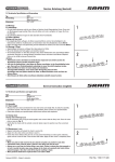
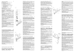
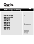
DE
Beiblatt zur Montageund Wartungsanleitung RWT
Rotationswärmetauscher RWT in geteilter Ausführung
Baugröße 600 - 1000
Seite 2 - 4 / 17 - 41
GB
Supplementary sheet for the installation
and maintenance manual RWT
Heat wheel heat exchanger RWTin split version
Unit size 600 - 1000
Pages 5 - 7 / 17 - 41
FR
Feuillet supplémentaire au guide
d’installation et d’entretien des blocs de
traitement d’air RWT
Modèle d ‘Echangeur Cylindrique de chaleur séparée RWT
Taille de centrale 600 - 1000
Page 8 - 10 / 17 - 41
RU
Приложение к инструкции по монтажу
и техническому обслуживанию
вентиляционных установок RWT
Вращающийся теплообменник RWT в раздельной версии
Типоразмер 600 - 1000
Страница 11 - 13 / 17 - 41
ES
Suplemento para la instalación y el
mantenimiento unidades manuales para
el tratamiento del aire RWT
Intercambiador de calor rotativo RWT en versión fragmentada
Tamaño 600 - 1000
Página 14 - 16 / 17 - 41
Wolf GmbH · Postfach 1380 · 84048 Mainburg · Tel. 08751/74-0 · Fax 08751/741600 · Internet: www.wolf-heiztechnik.de
Art.-Nr.: 3063143_201501 Änderungen vorbehalten!
DE
Sicherheitshinweise
Allgemeines
Die vorliegende Montageanleitung ist ausschließlich für Wolf-Rotationswärmetauscher RWT in geteilter Ausführung gültig. Diese Anleitung ist vor Beginn der Montage
von dem mit den jeweiligen Arbeiten beauftragten Personal zu lesen. Die Vorgaben,
die in dieser Anleitung gegeben werden, müssen eingehalten werden.
Montagearbeiten dürfen ausschließlich von ausgebildetem Fachpersonal durchgeführt werden.
Diese Montageanleitung ist als Bestandteil des gelieferten Gerätes für künftige
Verwendung zugänglich aufzubewahren. Bei Nichtbeachten der Montageanleitung
erlischt der Gewährleistungsanspruch gegenüber der Fa. Wolf.
Hinweiszeichen
In dieser Montageanleitung werden die folgenden Symbole und Hinweiszeichen
ververwendet. Diese wichtigen Anweisungen betreffen den Personenschutz
und die technische Betriebssicherheit.
„Sicherheitshinweis“ kennzeichnet Anweisungen, die genau einzuhalten sind,
um Gefährdung und Verletzung von Personen zu vermeiden und Beschädigungen am Gerät zu verhindern.
Gefahr durch elektrische Spannung an elektrischen Bauteilen!
Achtung: Vor Abnahme der Verkleidung Betriebsschalter ausschalten. Greifen
Sie niemals bei eingeschaltetem Anlagenschalter an elektrische Bauteile und
Kontakte! Es besteht die Gefahr eines Stromschlages mit Gesundheitsgefährdung oder Todesfolge. An Anschlußklemmen liegt auch bei ausgeschaltetem
Betriebsschalter Spannung an.
Achtung „Hinweis“ kennzeichnet technische Anweisungen, die zu beachten sind, um
Schäden und Funktionsstörungen am Gerät zu verhindern.
Sind am Gerät, zusätzlich zur Montageanleitung, Hinweise in Form von Aufklebern
angebracht, müssen diese in gleicher Weise beachtet werden.
Hinweiszeichen
Für Montage, Inbetriebnahme, Wartung und Betrieb des Gerätes muss ausreichend
qualifiziertes und eingewiesenes Personal eingesetzt werden.
Arbeiten an der Elektroanlage dürfen nur von Elektrofachkräften durchgeführt werden.
Für Elektroinstallationsarbeiten sind die Bestimmungen der VDE und des örtlichen
Elektro-Versorgungsunternehmens (EVU) maßgeblich.
Das Gerät darf nur innerhalb des Leistungsbereiches betrieben werden, der in den
technischen Unterlagen der Fa. Wolf vorgegeben ist.
Die bestimmungsgemäße Verwendung des Gerätes umfasst den ausschließlichen
Einsatz für Lüftungszwecke. Es darf nur Luft gefördert werden.
Diese darf keine gesundheitsschädlichen, brennbaren, explosiblen, aggresiven,
korrosionsfördernden oder in anderer Weise gefährlichen Bestandteile enthalten, da
ansonsten diese Stoffe im Kanalsystem oder Gebäude verteilt werden und die darin
lebenden Personen, Tiere oder Pflanzen in ihrer Gesundheit beeinträchtigt oder gar
getötet werden können.
Sicherheits- und Überwachungseinrichtungen dürfen nicht entfernt, überbrückt oder
in anderer Weise außer Funktion gesetzt werden.
Das Gerät darf nur in technisch einwandfreiem Zustand betrieben werden. Störungen
und Schäden, die die Sicherheit oder einwandfreie Funktion des Gerätes beeinträchtigen
oder beeinträchtigen können, müssen umgehend und fachmännisch behoben werden.
Schadhafte Bauteile und Gerätekomponenten dürfen nur durch Original-WOLFErsatzteile ersetzt werden.
Achtung Der Zusammenbau des RWT-Gehäuses ist unbedingt vor der eigentlichen KG-Gerätemontage durchzuführen.
Grund: Allseitig freie Zugänglichkeit für den RWT-Zusammenbau erforderlich (Verwendung eines Montagegerüstes wird empfohlen).
Für die Aufstellung des Rotationswärmetauschers ist ein ebener, waagerechter und
ausreichend tragfähiger Untergrund erforderlich.
2
3063143_201501
Montage des RWT-Gehäuses
Hinweis
Das Montagematerial zum Zusammenbau des RWT befindet sich im RWT Gehäuse,
das Verbindungsmaterial (Schrauben und Muttern) zum Verbinden des Klimagerätes
mit dem RWT befindet sich im Klimagerät.
Details zum Zusammenbau sind den beiliegenden, selbsterklärenden Bildern zu entnehmen
Montage des RWT-Gehäuses
Gehäuse-Unterteile (Pos. 1 und 2) an der vorgesehenen Stelle auf dem bauseitigen
Fundament positionieren.
Skizze 1
Gehäuse-Oberteile (Pos. 2) auf die Gehäuse-Unterteile (Pos. 1) aufsetzen und mit
beiliegendem Verbindungsmaterial alle Gehäuseteile untereinander verbinden.
(siehe Skizze 1 und 2)
Detail P
Nach der Rotormittenzentrierung die Montage der übrigen Speichen (Pos. 3) mit dem
Verbindungsmaterial durchführen.
i
be
g
un e
ht ag
ric nt
eh Mo
Dr der
Einschubrichtung
Fixierung der
Speichermasse
Skizze 2
3063143_201501
3
Montage des Rotors
Montage des Rotors
i
be
g
un e
ht ag
ric nt
eh M o
D r der
Einschubrichtung
Fixierung der
Speichermasse
Skizze 2
Das erste Rotorsegment auf die fixierte Speiche aufschieben und mit dem Alu-Prisma
(Pos. 4 – Skizze 2) zur Speiche (Pos. 3 – Skizze 1) sichern.
Anschließend das Segment mit dem Außenabdichtblech (Pos. 5 – Skizze 2) sichern.
Die übrigen Segmente entsprechend montieren. Dabei die Drehrichtung entsprechend Skizze 2 beachten. Jedes Außenabdichtblech (Pos. 5 – Skizze 2), unter
Beachtung der geteilten Bohrungen, unter das vorgehende Außenabdichtblech
einschieben und mit den Klemmschrauben sichern (Pos B – Skizze 2). Segmente
gegenseitig zusammenziehen.
Nach Montage aller Segmente Klemmschrauben (Pos. B – Skizze 2) noch mal fest
nachziehen.
Rotorlagerabdeckung (Pos. 6 – Skizze 2) zu den Speichen (Pos. 3 – Skizze 1) mit
dem beiliegendem Befestigungsmaterial montieren.
Gehäuse
Rotor
Skizze 3
Abschlußmontagearbeiten
Zum Rotorbereich hin, die Dichtlippen mit den Befestigungsfedern (Pos. 7 – Skizze
3) und den Blechstreifen (Pos. 8 – Skizze 3) befestigen.
Über den ganzen Umfang hin, die Abdichtung mit den Dichtlippen dementsprechend
durchführen.
Nach Abschluß der Arbeiten, Mittenabdeckung (Pos. 9 – Skizze 3) montieren.
Nach Abschluß der Arbeiten Rotor und Motor mit dem Antriebsriemen (offener
Keilriemen mit Verschlußglied) verbinden und äußere Gehäuseverkleidungsplatten
montieren.
Testlauf durchführen, Rotor darf nicht am Gehäuse streifen, Dichtungen müssen eng
anliegen.
Abdichten der Montage-Spalten am äusseren Gehäuse zur Verhinderung möglicher
Leckagen.
4
3063143_201501
GB
Safety instructions
Preface
The present installation manual is only valid for Wolf heat wheel heat exchanger
RWT in split version. This manual has to be read by the personnel instructed with the
particular operations before installation, start up and maintenance.
The requirements stated in this manual have to be met.
Installation work is exclusively permitted to be done by skilled and specialised staff.
The installation and maintenance manual has to be kept accessible as a part of the
unit for future purposes.
Failure to comply with this manual will lead to expiration of the warranty claim to Wolf.
Signs
The following symbols and signs are used in this installation manual. Theses
important instructions concern personal security and the technical safety in
operation.
“Security advice“ marks the instructions that have to be met exactly to prevent
endangerment and injury of persons and to avoid damages at the unit.
Danger aroused by voltage on electrical parts!
Warning: Before you take off the cover, switch-off engage switch. Never touch
any electrical parts and connections when engage switch is switched on!
An electric shock with health risk or death result might be the danger.
There is also voltage at the connecting terminal when the operating switch is
switched on.
NB
„Advice“ marks technical instructions, that have to be kept in mind in order to
avoid damages and malfunction at the unit.
If there is any advice in addition to the installation manual sticked to the unit as a
label, they have to be adhered to in the same way.
Safety advice
For installation, start up and operation of the unit, a sufficiently qualified and briefed
staff has to be employed.
Operations at the electrical installation are only allowed to be carried out by skilled
electricians.
For electrical installations the regulations of the VDE and the public utility (EVU) are
decisive.
The unit is only allowed to be operated within the range of performance set in the
technical documentations of Wolf.
The conventional use of the unit includes the exclusive application for ventilation
purposes. Only air is allowed to be transported.
This must not contain harmful, combustible, explosive, aggressive, corrosion- promotion or in any other way dangerous parts, as otherwise these substances could be
spread in the pipe system of the building and the people, animals and plants living in
the building could be affected in their health or even be killed.
Safety and surveillance installations are not allowed to be removed, bypassed or in
any other way be put out of operation.
The unit is only permitted to be operated in technical sound state. Damages that
affect or might affect the function of the unit have to be rectified immediately by an
expert.
Defective parts and unit components are only allowed to be replaced by original
WOLF spare parts.
NB
The assembly of the heat wheel heat exchanger casing necessarily has to be effected before the actual unit assembly.
Reason: all-round free accessibility necessary for the assembly of the heat wheel
heat exchanger (the use of a installation gantry is recommended).
For the assembly of the heat wheel heat exchanger a flat, horizontal and sufficiently
stable ground is necessary.
3063143_201501
5
Installation of
the heat wheel heat exchanger casing
Advice
The installation material for the assembly of the heat wheel heat exchanger is located
in the heat wheel heat exchanger casing, the connection material (screws and nuts)
to connect the air handling unit with the heat wheel heat exchanger is located in the
air handling unit.
Details for the assembly can be taken from the enclosed self-explaining images:
Installation of the heat wheel heat exchanger casing
Position the casing bottom parts (pos. 1 and 2) on the designated place on the onsite foundation
drawing 1
Put casing top parts (pos. 2) onto the casing bottom parts (pos. 1) and connect all
casing parts to each other using the attached connection material. (see drawing 1
and 2)
detail P
After rotor alignment the installation of the remaining spokes with the connection
material has to be effected (Pos. 3).
ion
tat
f ro ted
n o un
tio mo
ec
dir hen
w
insertion direction
fixation of
storagemass
drawing 2
6
3063143_201501
Installation of the rotor
Installation of the rotor
ion
tat
f ro ted
n o un
tio mo
ec
dir hen
w
insertion direction
fixation of
storagemass
drawing 2
Slide on the first rotor section onto the fixed spokes and and secure it with the aluminium prism (pos. 4 – drawing 2) to the spoke (pos. 3 – drawing 1). Afterwards,
secure the section with the outside sealing sheet (pos. 5 – drawing 2).
Assemble the remaining sections accordingly. Please note the direction of rotation
according to drwaing 2. Insert every outside sealing sheet (pos. 5 – drawing 2), considering the separated drillings, under the anterior outside sealing sheet and secure
with the locking screws (pos B – drawing 2). Contract sections reciprocal.
After the installation of all sections, retighten the locking screws (pos. B – drawing 2)
again firmly.
Assemble the rotor bearing covers (pos. 6 – drawing 2) to the spokes (pos. 3 – drawing 1) with the attached fixing material.
case
Rotor
Final installation workings
Fix the sealing lips with the fixing springs (pos. 7 – drawing 3) and the metal strips
(pos. 8 – drawing 3) in direction to the rotor area.
Conduct the sealing correspondingly with the sealing lips through the whole length.
drawing 3
After having finished the workings, install centre cover (pos. 9 – drawing 3).
After having finished the workings, connect rotor and motor with the driving belt (open
v-belt with locking element) and mount outside casing cover panels.
Carry out test run, rotor must not touch the casing, sealing have to fit tightly.
3063143_201501
7
FR
Conseils de sécurité
Préface
Ce guide d‘installation n‘est uniquement valable que pour le modèle d‘échangeur
cylindrique de chaleur séparée (RWT). Ce guide doit être lu par le personnel responsable des tâches spécifiques avant l’installation, le démarrage et l’entretien.
Les conditions stipulées dans ce guide doivent être respectées.
Les tâches d’installation doivent être uniquement effectuées par un personnel compétent et spécialisé.
Le guide d’installation et d’entretien doit être conservé à proximité comme partie
intégrante de l’appareil pour références ultérieures.
Toutes non conformité à ce guide rendra la garantie de Wolf caduque.
Signalétiques
Les symboles et signalétiques suivants sont utilisés dans ce guide
d’installation. Ces consignes importantes concernent la sécurité du personnel
et la sécurité technique pendant le fonctionnement.
’Consignes de sécurité’’ définissent les instructions devant être respectées afin d’éviter tout danger et blessures aux personnes et pour éviter
l’endommagement de l’appareil.
Danger potentiel de tension sur les parties électriques!
Attention : Eteindre l’interrupteur de démarrage avant de retirer la carrosserie. Ne jamais toucher les parties électriques et les branchements lorsque
l’interrupteur est allumé!
Un choc électrique nuisible à la santé ou provoquant la mort peut être dangereux.
La tension est aussi présente au point de branchement lorsque l’interrupteur
de marche est allumé.
Attention „Conseil’’ indique les instructions techniques devant être retenues afin d’éviter
l’endommagement ou le mauvais fonctionnement de l’appareil.
Si des consignes supplémentaires au guide d’installation sont collées sur l’appareil
comme signalétiques, elles doivent être aussi respectées.
Consignes de Sécurité
Un personnel suffisamment qualifié et informé devra être employé pour l’installation;
le démarrage et le fonctionnement de l’appareil.
Les tâches d’installation électriques ne doivent être effectuées que par des électriciens qualifiés.
Les règlementations VDE et d’utilité publique (EVU – Norme de qualité allemande)
sont obligatoires pour les installations électriques.
Il n’est permis d’utiliser l’appareil que dans les capacités de performance dont
l’objectif est décrit dans la documentation technique de Wolf.
L’utilisation conventionnelle de l’appareil a pour but l’objectif exclusif de ventilation.
Seul de l’air peut être transporté.
Il ne doit comporter aucun élément propice à la nuisance, combustion, explosion,
agression corrosion ou en aucun cas des éléments dangereux, car autrement ces
substances pourraient se propager dans le système de tuyauterie du bâtiment et
nuire à la santé des personnes, des animaux et des plantes vivants dans le bâtiment
ou même en provoquer la mort.
Il est interdit de retirer, dévier ou d‘empêcher par quelques moyens le fonctionnement, la sécurité et la surveillance des installations.
L’appareil ne peut seulement être utilisé qu’en bon état technique. Des endommagements affectant ou pouvant affecter la fonction de l’appareil doivent être immédiatement réparés par un spécialiste.
Les pièces défectueuses et les composants de l’appareil ne peuvent être remplacés
que par des pièces de rechanges d’origine WOLF.
Attention Le montage de la carrosserie de l’échangeur cylindrique de chaleur doit obligatoirement être effectué avant le montage de l’appareil même.
Raison : L’accessibilité tout autour est nécessaire pour le montage de l’échangeur
cylindrique de chaleur (l‘utilisation d’une tour d’installation est conseillée).
Le montage de l’échangeur cylindrique de chaleur doit être effectué sur un sol plat,
horizontal et suffisamment solide.
8
3063143_201501
Installation de la carrosserie de
l’échangeur cylindrique de chaleur
Conseil
Les éléments d’assemblée de l’installation de l’échangeur cylindrique de chaleur se
trouvent dans la carrosserie de ce dernier; les accessoires de raccordements (vis
et écrous) pour brancher le bloc du traitement de l‘air à l‘échangeur cylindrique de
chaleur, se trouvent dans le bloc du traitement de l’air.
Les descriptions du montage peuvent être obtenues à partir des illustrations explicatives ci-jointes:
Installation de la carrosserie de l’échangeur cylindrique de chaleur
Positionner les parties inférieures de la carrosserie (pos. 1 et 2) sur l’endroit indiqué
sur la base du site
Illustration 1
Placer les parties supérieures de la carrosserie (pos. 2) sur les parties inférieures de
cette dernière (pos. 1) et fixer toutes les parties de la carrosserie les unes aux autres
en utilisant les accessoires de raccordement. (voir illustrations 1 et 2)
détail P
Après l’alignement du rotor, il faut procéder à l’installation des rayons restants avec
les accessoires de raccordement (pos. 3).
n
tio e
ta
ro tag
de on
ns e m
Se ur l
po
sens de l‘insertion
Fixation du stockage de masse
Illustration 2
3063143_201501
9
Installation du rotor
Installation du rotor
n
tio e
ta
ro tag
de on
ns e m
Se ur l
po
sens de l‘insertion
Fixation du stockage de masse
Illustration 2
Faire glisser la première partie du rotor sur les rayons en place et la fixer avec le prisme en aluminium (pos. 4 – illustration 2) au rayon (pos. 3 – illustration 1). Ensuite,
fixer la section avec la toile d’étanchéité extérieure (pos. 5 – illustration 2).
Monter conformément les parties restantes.
Veuillez noter le sens de la rotation comme sur l’illustration 2. Insérer toutes les toiles
d’étanchéité extérieures (pos. 5 – illustration 2), en faisant attention aux perforations individuelles sous la toile d’étanchéité extérieure précédente et les fixer avec
les vis de blocage (pos B – illustration 2). Rétracter les parties superposées.
Après l’installation de toutes les parties, reserrer à nouveau fermement les vis de
blocage (pos. B – illustration 2).
Monter les caches des roulements du rotor (pos. 6 – illustration 2) aux rayons (pos.
3 – illustration 1) avec les accessoires de fixation inclus.
carrosserie
rotor
Tâches finales d‘installation
Fixer les lèvres d’étanchéité avec les ressorts de fixation (pos. 7 – illustration 3) et les
bandes métalliques (pos. 8 – illustration 3) dans le sens de l‘emplacement du rotor.
Positionner le joint conformément aux lèvres d’étanchéité sur toute la longueur.
Illustration 3
Une fois terminé, installer le cache du milieu (pos. 9 – illustration 3).
Une fois les tâches terminées, relier le rotor et le moteur avec la courroie de transmission (ouvrir la courroie trapézoïdale avec la pièce de blocage) et poser les panneaux extérieurs de la carrosserie.
Effectuer un essai, le rotor ne doit pas toucher la carrosserie, les joints devant être
fermement en place.
10
3063143_201501
RU
Указания по технике безопасности
Введение
Данная инструкция по монтажу применима только для вращающегося теплообменника
RWT Wolf в разъемной конструкции. Перед началом работ по монтажу, вводу
в эксплуатацию и техническому обслуживанию персонал, уполномоченный на
проведение данных работ, должен ознакомиться с этой инструкцией.
Необходимо соблюдать все требования, указанные в данной инструкции.
Работы по монтажу может выполнять только специально подготовленный
квалифицированный персонал.
Необходимо хранить эту инструкцию по монтажу и техническому обслуживанию
рядом с устройством для будущего использования.
При несоблюдении данной инструкции гарантия на оборудование утрачивается
и любые претензии по гарантии к компании Wolf не принимаются.
Знаки
В данной инструкции по монтажу используются следующие знаки и
символы. Эти важные указания касаются безопасности персонала и
технической безопасности в процессе эксплуатации.
„Знак “Меры безопасности“ означает указания, которые необходимо
строго соблюдать для предотвращения опасности и травмирования
персонала, а также повреждения оборудования.
Опасность поражения электрическим током от частей оборудования,
находящихся под напряжением!
Предупреждение: Перед снятием крышки обесточьте оборудование.
Никогда не прикасайтесь к электрокомпонентам и контактам, находящимся
под напряжением! Существует опасность поражения электрическим током
с угрозой для здоровья или летальным исходом.
На соединительных клеммах также присутствует напряжение при
включенном выключателе установки.
Внимание Знак “Внимание“ отмечает технические требования, которые необходимо
соблюдать во избежание повреждений и нарушений в работе устройства.
В случае, если на устройство дополнительно наклеены знаки, необходимо
также соблюдать их.
Указания по технике безопасности
Работы по монтажу, вводу в эксплуатацию и обслуживанию устройства должны
выполняться квалифицированным и проинструктированным персоналом.
Работы с электрическими компонентами установки могут выполнять только
квалифицированные электрики.
При проведении электромонтажных работ следует руководствоваться
требованиями VDE и местными правилами предприятий бытового
обслуживания (EVU).
Эксплуатация устройства допускается только по назначению, указанному в
технической документации Wolf.
Использование устройства по назначению подразумевает его использование
только в целях вентиляции. Допускается подача только воздуха.
В нем не должны содержаться опасные, горючие, взрывчатые,
сильнодействующие, вызывающие коррозию или представляющие иную
опасность компоненты, иначе они могут попасть в систему трубопроводов
здания и нанести вред здоровью, или даже привести к гибели людей, животных
и растений, находящихся в здании.
Недопустимо снимать, перемыкать или каким-либо другим способом выводить
из строя защитные и контрольные устройства.
Разрешается эксплуатация устройства только в исправном состоянии. Все
повреждения и неисправности, которые оказывают или могут оказать влияние на
функционирование устройства, должны быть немедленно устранены специалистом.
Неисправные детали и компоненты устройства могут быть заменены только на
оригинальные запасные части производства компании WOLF.
Внимание Монтаж корпуса вращающегося теплообменника необходимо в обязательном
порядке осуществить до монтажа самого устройства.
Причина: для монтажа вращающегося теплообменника необходимо наличие свободного
доступа со всех сторон (рекомендуется использование монтажной конструкции).
Для монтажа вращающегося теплообменника необходима ровная,
горизонтальная и достаточно устойчивая поверхность.
3063143_201501
11
Монтаж корпуса вращающегося
теплообменника
Совет
Монтажные материалы для монтажа вращающегося теплообменника находятся
в корпусе теплообменника, соединительные материалы (болты и гайки) для
соединения вентиляционной установки с вращающимся теплообменником,
находятся в вентиляционной установке.
С подробностями процесса монтажа можно ознакомиться на прилагаемых рисунках:
Монтаж корпуса вращающегося теплообменника
Расположите нижнюю часть корпуса (поз. 1 и 2) на предназначенном месте на
рабочем основании
Рисунок 1
Поместите верхнюю часть (поз. 2) на нижнюю часть корпуса (поз. 1) и
соедините все части корпуса друг с другом, используя соединительные
материалы. (см. рисунок 1 и 2)
деталь P
После выравнивания ротора необходимо произвести монтаж остальных спиц,
используя соединительные материалы (поз. 3).
е ке
ни ор
ле сб
ав ри
пр я п
На ни
е
щ
а
вр
Вставка
направлении
фиксация
запоминающего
Рисунок 2
12
3063143_201501
Монтаж ротора
Монтаж ротора
е к
ни ор
ле сб
ав ри
пр я п
На ни
е
ащ
вр
е
Рисунок 2
Вставка
направлении
Наденьте первую секцию ротора на зафиксированные спицы и закрепите ее
алюминиевой призмой (поз. 4 – рисунок 2) на спице (поз. 3 – рисунок 1).
После этого, закрепите секцию внешним уплотняющим листом (поз. 5 – рисунок 2).
Смонтируйте оставшиеся секции соответствующим образом.
Пожалуйста, обратите внимание на направление вращения в соответствии с
рисунком 2.
Вставьте каждый внешний уплотняющий лист (поз. 5 – рисунок 2), учитывая
фиксация
отдельные отверстия, под предыдущий уплотняющий лист и закрепите
запоминающего
крепежными болтами (поз. B – рисунок 2).
Скрепите секции друг с другом.
После монтажа всех секций повторно крепко затяните крепежные болты (поз.
B – рисунок 2).
Соедините крышки подшипника ротора (поз. 6 – рисунок 2) со спицами (pos. 3
– drawing 1) при помощи прилагающихся крепежных деталей.
корпус
ротор
Рисунок 3
Окончательные работы по монтажу
Закрепите уплотнительную кромку посредством крепежных пружин (поз. 7 –
рисунок 3) и металлических полос (поз. 8 – рисунок 3) в направлении зоны
ротора.
Осуществите таким образом герметизацию по всей длине.
По завершении работ, установите верхнюю крышку (поз. 9 – рисунок 3).
После завершения работ, соедините ротор и мотор приводным ремнем
(откройте клиновидный ремень запирающим элементом) и установите внешние
панели корпуса.
Выполните тестовый запуск, ротор не должен задевать корпус, уплотнители
должны быть хорошо зафиксированы.
3063143_201501
13
ES
Advertencias de seguridad
Prefacio
Este Manual de instalación sólo es válido para el intercambiador de calor rotativo RWT
de Wolf en versión fragmentada. El personal formado en las operaciones concretas debe
leer este manual antes de realizar la instalación, puesta en marcha y mantenimiento.
Deben cumplirse los requisitos indicados en este manual.
Las tareas de instalación sólo están permitidas si las realiza personal especializado y
con la destreza necesaria.
El manual de instalación y mantenimiento debe guardarse en un lugar accesible
como parte de la unidad, para su uso futuro.
La no adherencia a este manual llevará a la finalización del reclamo de la garantía a Wolf.
Señales
En este Manual de instalación se utilizan los siguientes símbolos y señales.
Estas importantes instrucciones se refieren a seguridad personal y a la seguridad técnica durante el funcionamiento.
„Advertencia de seguridad“indica las instrucciones que deben cumplirse exactamente para prevenir riesgos y lesiones personales y para evitar daños en la
unidad.
¡Peligro por el voltaje en las partes eléctricas!
Advertencia: antes de retirar la cubierta, desconecte el enchufe. ¡Nunca toque
piezas eléctricas ni conexiones cuando el enchufe de conexión esté conectado!
Podría haber peligro de choque eléctrico con resultado de muerte o riesgo
para la salud.
También hay voltaje en la terminal de conexión cuando el interruptor operante
está conectado.
Atención “Consejo“indica instrucciones técnicas, que deben tenerse en cuenta para
evitar daños y un funcionamiento inadecuado de la unidad.
En caso de que haya algún consejo, aparte de los del manual de instalación adheridos a la unidad en forma de etiqueta, deberá estar adherido del mismo modo.
Advertencia de seguridad
Para la instalación, puesta en marcha y funcionamiento de la unidad, debe contratarse personal suficientemente cualificado e instruido.
Las operaciones en la instalación eléctrica sólo deben ser efectuadas por electricistas
competentes.
En instalaciones eléctricas son decisivas la normativa VDE y la de utilidad pública (EVU).
Sólo se permite utilizar la unidad dentro del rango de rendimiento especificado en la
documentación técnica de Wolf.
El uso convencional de la unidad incluye la aplicación exclusiva para fines de ventilación. Sólo se permite el transporte de aire.
Éste no debe contener partes dañinas, combustibles, explosivas, agresivas, que
favorezcan la corrosión u otros peligros, ya que de lo contrario dichas sustancias
podrían diseminarse por el sistema de tuberías del edificio afectando a la salud
de personas, animales y plantas que vivan en el edificio, incluso hasta el punto de
causar la muerte.
No se permite eliminar, evitar ni privar de su funcionamiento a las instalaciones de
seguridad y vigilancia.
Sólo se permite el manejo de la unidad si su estado técnico es el adecuado. Deben
solucionarse inmediatamente, por parte de un experto, los daños que afecten o
pudieran afectar al funcionamiento de la unidad.
Las piezas defectuosas y los
Atención El montaje de la carcasa del intercambiador de calor rotativo debe efectuarse necesariamente antes de montar la unidad propiamente dicha.
Motivo: se necesita libre accesibilidad en todas las proximidades para el montaje del
intercambiador de calor rotativo (es aconsejable utilizar una instalación de pórtico).
Para montar el intercambiador de calor rotativo necesita una superficie horizontal,
plana y suficientemente estable.
14
3063143_201501
Instalación de la carcasa del intercambiador de calor rotativo
Consejo
El material de instalación para el montaje del intercambiador de calor rotativo se
encuentra en la carcasa del mismo; el material de conexión (tornillos y tuercas) para
conectar la unidad de tratamiento del aire con el intercambiador de calor rotativo se
encuentra en dicha unidad.
Puede ver los detalles de montaje en las imágenes auto-explicativas adjuntas:
Instalación de la carcasa del intercambiador de calor rotativo
Sitúe las piezas inferiores de la carcasa (pos. 1 y 2) en el lugar indicado sobre la
base de instalación in-situ.
dibujo 1
Coloque las piezas superiores de la carcasa (pos. 2) sobre las piezas inferiores de
ésta (pos. 1) y conecte todas las partes de la carcasa entre sí utilizando el material
de conexión adjunto (ver dibujos 1 y 2)
detalle P
Una vez alineado el rotor debe efectuarse la instalación de los radios restantes con
el material de conexión (pos. 3)
ro
gi e
de aj
o ont
id
nt l m
Se ra e
pa
dibujo 2
3063143_201501
inserción de la
dirección
La fijación de
la memoria de
masa
15
Instalación del rotor
Instalación del rotor
ro
gi e
de aj
o ont
id
nt l m
Se ra e
pa
inserción de la
dirección
Ensamble las secciones restantes en consonancia.
Por favor, tenga en cuenta la dirección de la rotación según el dibujo 2. Introduzca
cada hoja de sellado externa (pos. 5 – dibujo 2), teniendo en cuenta la separación de
las perforaciones, bajo la anterior hoja de sellado externa y fíjela con los tornillos de
La fijación de
bloqueo (pos B – dibujo 2). Ajuste recíprocamente las secciones.
la memoria de
masa
dibujo 2
Deslice la primera sección del rotor en los radios fijados y fíjela con el prisma de
aluminio (pos. 4 – dibujo 2) al radio (pos. 3 – dibujo 1).
A continuación, fije la sección con la hoja de sellado externa (pos. 5 – dibujo 2).
Una vez instaladas todas las secciones, vuelva a reajustar firmemente los tornillos
de bloqueo (pos. B – dibujo 2).
Ensamble las cubiertas del cojinete rotor (pos. 6 – dibujo 2) a los radios (pos. 3 –
dibujo 1) con el material de fijación adjunto.
carcasa
rotor
Tareas de instalación final
Fije los labios de sellado con los resortes de fijación (pos. 7 – dibujo 3) y las tiras
metálicas (pos. 8 – dibujo 3) en dirección hacia el área del rotor.
Realice el correspondiente sellado, en toda su longitud, con los labios de sellado.
dibujo 3
Una vez finalizadas las tareas, instale la cubierta central (pos. 9 – dibujo 3).
Una vez finalizadas las tareas, conecte el rotor y el motor con la correa de transmisión (correa-V abierta con elemento de bloqueo) e instale exteriormente los paneles
para cubrir la carcasa.
Efectúe un ciclo de prueba; el rotor no debe tocar la carcasa, el sellado debe ajustar
perfectamente.
16
3063143_201501
DE GB FR RU ES
01
-
-
-
-
-
Ansicht des Unterteiles
view of the lower part
Vue de la partie inférieure
pohled na spodní díl
vista de la parte inferior
-
-
-
-
-
Demontage der Transportbefestigung
dismantling of the transport preparation
Démontage des préparatifs de transport
разбор после транспортировки
desmontaje de la preparación del transporte
02
3063143_201501
17
03
-
-
-
-
-
Aufbringen der Gehäuseabdichtung
apply the sealing between the casings
Faire les joints entre les carrosseries
применяйте уплотнители между корпусами
aplicación del sellado entre las carcasas
-
-
-
-
-
Montage des oberen Halbkastens
assembly of the upper part of the casing
Montage de la partie supérieure de la carrosserie
монтаж верхней части корпуса
montaje de la parte superior de la carcasa
04
18
3063143_201501
05
-
-
-
-
-
RWT Gehäuse mit den unteren Rotorsegmenten
casing as a whole
Carrosserie entière
корпус в сборе
la carcasa como un todo
-
-
-
-
-
Verschraubung des oberen + unteren RWT Gehäuses
blocking of the upper half of the casing (detail)
Blocage de la moitié supérieure de la carrosserie (détaillé)
фиксация верхней половины корпуса (деталь)
bloqueo de la mitad superior de la carcasa (detalle)
06
3063143_201501
19
07
-
-
-
-
-
Verschraubung des oberen + unteren RWT Gehäuses
blocking of the upper half of the casing (detail)
Blocage de la moitié supérieure de la carrosserie (détaillée)
фиксация верхней половины корпуса (деталь)
bloqueo de la mitad superior de la carcasa (detalle)
-
-
-
-
-
Verschraubung des oberen + unteren RWT Gehäuses
blocking of the upper half of the casing (detail)
Blocage de la moitié supérieure de la carrosserie (détaillée)
фиксация верхней половины корпуса (деталь)
bloqueo de la mitad superior de la carcasa (detalle)
08
20
3063143_201501
09
-
-
-
-
-
Verschraubung des oberen + unteren RWT Gehäuses
blocking of the upper half of the casing (detail)
Blocage de la moitié supérieure de la carrosserie (détaillée)
фиксация верхней половины корпуса (деталь)
bloqueo de la mitad superior de la carcasa (detalle)
-
-
-
-
-
Vernietung umlaufende Halterung für Filzdichtung
the peripheral sealing metal plate connection
Raccord du joint de la plaque d’étanchéité circulaire métallique
присоединение металлической пластины к расположенному по кругу уплотнителю
conexión de la placa metálica con sellado periférico
10
3063143_201501
21
11
-
-
-
-
-
Vernietung umlaufende Halterung für Filzdichtung
the peripheral sealing metal plate connection
Raccord du joint de la plaque d’étanchéité circulaire métallique
присоединение металлической пластины к расположенному по кругу уплотнителю
conexión de la placa metálica con sellado periférico
-
-
-
-
-
Vernietung der Spülkammer
the purging sector tack
Partie de l‘orifice de purge
подсоединение промывной камеры
disposición del sector de purga
12
22
3063143_201501
13
-
-
-
-
-
Montage der Strahlbleche der oberen Rotorsegmente
the upper part rotor radius assembly
Montage du rayon de la partie supérieure du rotor
монтаж радиуса верхней части ротора
montaje del radio rotor de la parte superior
-
-
-
-
-
Montagestrahlen des oberen Rotors
the upper part rotor radius assembly (detail)
Montage du rayon de la partie supérieure du rotor (détaillé)
монтаж радиуса верхней части ротора (деталь)
montaje del radio rotor de la parte superior (detalle)
14
3063143_201501
23
15
-
-
-
-
-
Zentrieren der Rotorstrahlen
rotor radius centering
centrage du rayon du rotor
центрирование радиуса ротора
centrado del radio rotor
-
-
-
-
-
Montage der Rotorstrahlen
the rotor radius assembly (detail)
Montage du rayon du rotor (détaillé)
монтаж радиуса ротора (деталь)
montaje del radio rotor (detalle)
16
24
3063143_201501
17
-
-
-
-
-
RWT Gehäuse mit oberen Rotorstrahlen
view of the mounted radii
Vue du rayon monté
вид смонтированного радиуса ротора
vista de los radios montados
18
-
-
-
-
Sicherung des Rotors zur Montage der weiteren Segmente
rotor blocking against slewing during the assembly of other segments
Blocage du rotor contre la rotation pendant le montage des autres sections
фиксация ротора для предотвращения его вращения во время монтажа
других сегментов
- bloqueo del rotor para evitar giros bruscos durante el montaje de otros segmentos
3063143_201501
25
19
-
-
-
-
-
Rotorsicherung (Detail)
rotor blocking (detail)
Blocage du rotor (détaillé)
фиксация ротора (деталь)
bloqueo del rotor (detalle)
-
-
-
-
-
Auflegen des Einschubbleches für die Segmente
apply the drawer-sheet for the rotor segment
Pose de la plaque tiroir pour la section du rotor
установка выдвижного листа на сегмент ротора
aplicación del módulo para el segmento rotor
20
26
3063143_201501
21
-
-
-
-
-
Montage der Rotorsegmente
rotor segment assembly progress
Montage en cours de la section du rotor
продолжение процесса монтажа сегмента ротора
progreso del montaje del segmento rotor
-
-
-
-
-
Montage der Rotorsegmente
rotor segment assembly progress
Montage en cours de la section du rotor
продолжение процесса монтажа сегмента ротора
progreso del montaje del segmento rotor
22
3063143_201501
27
23
-
-
-
-
-
Montage der Rotorsegmente
rotor segment assembly progress
Montage en cours de la section du rotor
продолжение процесса монтажа сегмента ротора
progreso del montaje del segmento rotor
-
-
-
-
-
Montage der Rotorsegmente
rotor segment assembly progress
Montage en cours de la section du rotor
продолжение процесса монтажа сегмента ротора
progreso del montaje del segmento rotor
24
28
3063143_201501
25
-
-
-
-
-
Montage der Rotorsegmente
rotor segment assembly progress
Montage en cours de la section du rotor
продолжение процесса монтажа сегмента ротора
progreso del montaje del segmento rotor
-
-
-
-
-
Montage der Rotorsegmente
rotor segment assembly progress
Montage en cours de la section du rotor
продолжение процесса монтажа сегмента ротора
progreso del montaje del segmento rotor
26
3063143_201501
29
27
-
-
-
-
-
Verschraubung der Rotorsegmente
fixation of the rotor segment
Fixation de la section du rotor
фиксация сегмента ротора
fijación del segmento rotor
-
-
-
-
-
Verschraubung der Rotorsegmente (Detail)
fixation of the rotor segment (detail)
Fixation de la section du rotor
фиксация сегмента ротора (деталь)
fijación del segmento rotor (detalle)
28
30
3063143_201501
29
-
-
-
-
-
Schraubbefestigung der Rotorummantelung
bolts slacking in the rotor coating
Relâchement des écrous du cache du rotor
ослабленные винты в обшивке ротора
pernos aflojados en el revestimiento del rotor
-
-
-
-
-
Einbau weiterer Teile der Rotorummantelung
finsertion of the another part of the rotor coating
Insertion d’une autre partie de l’habillage du rotor
установка другой части обшивки ротора
inserción de otra parte del revestimiento del rotor
30
3063143_201501
31
31
-
-
-
-
-
Mantelbefestigung des oberen Teil-Rotores
the upper part rotor coating fixing
Fixation de l’habillage de la partie supérieure du rotor
фиксация верхней части обшивки ротора
fijación de revestimiento del rotor de la parte superior
32
- Abschluss der Rotorummantelung (Detail): die Rotorsegmente sind umlaufend
gekennzeichnet Rotorsegmente sind peripherisch
- delimitation of the rotor circumference (detail) the rotor segments are peripherally
pulled together
- Délimitation de la circonférence du rotor (détaillée); les sections du rotor sont rapprochées les unes aux autres dans leur périphérie
- закрытие оболочки ротора (деталь): поверхности сегментов ротора
соединяются по кругу
- delimitación de la circunferencia del rotor (detalle); los segmentos del rotor se
arrastran periféricamente de forma conjunta
32
3063143_201501
33
-
-
-
-
-
Verschraubung der Rotorummantelung
rotor coating fixing
Fixation de l’habillage du rotor
фиксация обшивки ротора
fijación del revestimiento del rotor
-
-
-
-
-
Montage der Rotorsegmente
rotor segment assembly progress
Montage en cours de la section du rotor
продолжение процесса монтажа сегмента ротора
progreso del montaje del segmento rotor
34
3063143_201501
33
35
- Teilweise verschraubte, lose Ummantelung
- the coating slackness for the assembly of the last segment rotor coating fixing
- Relâchement de l’habillage pour monter la fixation de l’habillage de la dernière section du rotor
- обшивка ослаблена для монтажа последнего сегмента крепления обшивки ротора
- holgura del revestimiento para montar el accesorio de revestimiento del rotor del
último segmento
36
-
-
-
-
-
34
Montage des letzten Rotorsegmentes
the assembly progress of the last segment
Montage en cours de la dernière section
процесс монтажа последнего сегмента
progreso del montaje del último segmento
3063143_201501
37
-
-
-
-
-
Montage des letzten Rotorsegmentes
the assembly progress of the last segment
Montage en cours de la dernière section
процесс монтажа последнего сегмента
progreso del montaje del último segmento
-
-
-
-
-
Verschraubte Ummantelung des Rotors
rotor coating assembly
Montage de l’habillage du rotor
монтаж обшивки ротора
montaje del revestimiento del rotor
38
3063143_201501
35
39
-
-
-
-
-
Spannen des Rotormantels (Detail)
delimitation of the rotor circumference (detail)
Délimitation de la circonférence du rotor (détaillée)
закрытие оболочки ротора (деталь)
delimitación de la circunferencia del rotor (detalle)
-
-
-
-
-
Verschraubung der Rotorummantelung
rotor coating fixation
Fixation de l’habillage du rotor
фиксация обшивки ротора
fijación del revestimiento del rotor
40
36
3063143_201501
41
-
-
-
-
-
Ansicht des RWT mit montiertem Rotor
view of the mounted rotor
Vue du rotor monté
вид смонтированного ротора
vista del rotor montado
-
-
-
-
-
Bohren der zentralen Rotorabdeckung auf die Segmente
assembly of the rotor centre covering
Montage de l’habillage de l’axe du rotor
монтаж центральной обшивки ротора
montaje de la cubierta del centro del rotor
42
3063143_201501
37
43
-
-
-
-
-
Vernieten der zentralen Rotorabdeckung auf die Segmente
assembly of the rotor centre covering
Montage de l’habillage de l’axe du rotor
монтаж центральной обшивки ротора
montaje de la cubierta del centro del rotor
-
-
-
-
-
Aufbringen der Lagerabdeckung
apply the cover of the bearing
Pose du cache du roulement
наденьте крышку подшипника
aplicación de la cubierta del cojinete
44
38
3063143_201501
45
-
-
-
-
-
Montage des Riementriebes (Verbindung des Endstückes)
V-belt assembly
Montage de la courroie trapézoïdale
Монтаж клиновидного ремня
montaje de la correa-V
-
-
-
-
-
montierter Antriebsriemen (Detail)
mounted V-belt (detail)
Courroie trapézoïdale montée (détaillée)
установленный клиновидный ремень (деталь)
correa-V montada (detalle)
46
3063143_201501
39
47
-
-
-
-
-
Spalt: Filzband – Rotor ca. 1-2mm
delimitation of the sealing backlash 1-2mmg
Délimitation du jeu d’étanchéité de 1 à 2 mm
ограничение зазора уплотнителя 1-2мм
delimitación de la holgura del sellado 1-2mm
-
-
-
-
-
Montage der isolierten Wand - Paneelen
assembly of the remained panels with the thermal insulation
Montage des panneaux restants avec l’isolation thermique
монтаж оставшихся панелей с термоизоляцией
ontaje del resto de paneles con aislamiento térmico
48
40
3063143_201501
49
-
-
-
-
-
3063143_201501
Abdichtung der Montagespalte
sealing of the connecting link to the units
Scellement des joints des connexions aux blocs
герметизация соединений элементов
sellado de la conexión con las unidades
41
42
3063143_201501
3063143_201501
43
Wolf GmbH · Postfach 1380 · 84048 Mainburg · Tel. 08751/74-0 · Fax 08751/741600 · Internet: www.wolf-heiztechnik.de