1
Safety precautions
Follow these precautions to ensure safe installation and
mounting of your flat panel TV.
1.
LCD TV Wall Mount
Installation Manual
2.
Fits TVs 23"- 37"
Maximum Load Capacity – 88 lb (39.9 kg)
3.
Make sure these instructions are read and completely
understood before attempting installation. If you
are unsure of any part of this installation, contact a
professional installer for assistance.
The wall or mounting surface must be capable of
supporting the combined weight of the wall mount and
the display; otherwise the structure must be reinforced.
Protective eye wear and proper tools must be used.
A minimum of two people are required for this
installation. Failure to use safety gear and/or attempting
this installation alone can result in property damage,
serious injury, or death.
Package Contents
Bag #
(Ref ) Item (Qty)
1
(A) M4x12 Bolt (x4)
Drywall Installation
(B) M4x30 Bolt (x4)
Important! For safety, this mount must be secured to
two adjacent wood studs no less than 16” apart.
(C) M4 Lock Washer (x4)
(D) M5x12 Bolt (x4)
2
(E) M5x30 Bolt (x4)
(F) M5 Lock Washer (x4)
3
(H) M6x35 Bolt (x4)
(I) M6 Lock Washer (x4)
adequate ventilation and suitable locations for mounting
your display in the owner‘s manual for your display.
5.
MAF70BK
Thank you for choosing the RCA MAF70BK Universal
Flat Panel TV Wall Mount. This mount can be used for all
major brands of 23" - 37" flat panel TVs, 88 lbs (39.9 kg) or
under. This wall mount features a 0-15-degree tilt for easy
viewing. Before attempting to mount your television set,
please remove all parts from this package and read the
installation instructions carefully.
WARNING: Use of this mount with a TV weighing
over 88 lbs. or with a screen larger than 37" could cause
the mount to fail causing property damage and/or
personal injury.
Limited Lifetime Warranty
Audiovox Electronics Corporation (the “Company”) warrants to you the
original retail purchaser of this product that should it, under normal use
and conditions, be proven defective in material or workmanship during
its lifetime while you own it, such defect(s) will be repaired or replaced (at
the Company’s option) without charge for parts and repair labor.
To obtain repair or replacement within the terms of this Warranty, the
product is to be delivered with proof of warranty coverage (e.g. dated bill
of sale), specification of defect(s), transportation prepaid, to the Company
at the address shown below. Do not return this product to the Retailer.
This Warranty does not cover product purchased, serviced or used
outside the United States or Canada.
This Warranty is not transferable and does not extend to costs incurred for
installation, removal or reinstallation of the product. This Warranty does
not apply if in the Company’s opinion, the product has been damaged
through alteration, improper installation, mishandling, misuse, neglect,
or accident.
THE EXTENT OF THE COMPANY’S LIABILITY UNDER THIS
WARRANTY IS LIMITED TO THE REPAIR OR REPLACEMENT
PROVIDED ABOVE AND, IN NO EVENT, SHALL THE COMPANY’S
LIABILITY EXCEED THE PURCHASE PRICE PAID BY PURCHASER
FOR THE PRODUCT.
This Warranty is in lieu of all other express warranties or liabilities. ANY
IMPLIED WARRANTIES, INCLUDING ANY IMPLIED WARRANTY
OF MERCHANTABILITY OR FITNESS FOR A PARTICULAR PURPOSE
SHALL BE LIMITED TO DURATION OF THIS WARRANTY. IN NO CASE
SHALL THE COMPANY BE LIABLE FOR ANY CONSEQUENTIAL OR
INCIDENTAL DAMAGES WHATSOEVER. No person or representative is
authorized to assume for the Company any liability other than expressed
herein in connection with the sale of this product.
Some states/provinces do not allow limitations on how long an implied
warranty lasts or the exclusion or limitation of incidental or consequential
damage so the above limitations or exclusions may not apply to you. This
Warranty gives you specific legal rights and you may also have other
rights which vary from state/province to state/province.
U.S.A.: Audiovox Electronics Corporation, 150 Marcus Blvd.,
Hauppauge, New York 11788
CANADA: Audiovox Return Center, c/o Genco, 6685 Kennedy Road,
Unit 3, Door 16, Mississauga, Ontario L5T 3A5
Trademark(s) Registered, Marques Deposee, Marcas Registradas.
All other brands and product names are trademarks or registered
trademarks of their respective owners.
© 2008 Audiovox Accessories Corporation
111 Congressional Blvd., Suite 350
Carmel, IN 46032
www.rca.com
MAF70BK_US_IB_00
6.
7.
8.
9.
Be sure you have purchased the correct wall mount
for your TV. Recheck the size and weight constraints.
Gather all necessary tools before you begin installation.
You will need a #3 bit Phillips screwdriver, electric
drill, drill bit (included), level (integrated level on
product), stud finder, and hammer (for brick and
concrete installations).
It is essential for the wall mount plate to be attached
to wall studs. (Use a stud finder.)
Use the included hardware for mounting purposes.
This hardware has been provided to ensure a safe and
secure mount.
4
3.
4.
5.
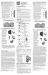
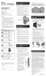
Attaching the Arms to the TV
Fig. 3
Attach the arms to the back
of your display.
Using a stud finder, locate and mark two adjacent studs
for securing the mount.
Place the wall plate against the wall and level it using
the bubble guide.
Mark four locations (two per stud) on the wall where
the mount will be secured. Be sure to use the center of
each stud.
With the help of another person, replace the wall
plate and level it using the bubble guide. Fix it to the
wall using the Lag Bolts (Q) and Lag Bolt Washers (R)
provided (Fig. 1).
1.
With the help of another person, carefully lift your
display and place it on the wall plate (Fig. 5). Do not
release the display until the mounting arms have
securely hooked onto the crossbars!
Fi 5
Fig.
Carefully hook the
display onto the wall plate.
2.
For displays with curved
or recessed backs...
Move the safety tab located on each arm into position
to avoid having the display accidentally lifted from the
mount. A padlock can be inserted into one of the tabs
to help prevent theft of your display (Fig. 6).
Fig. 6
A small padlock
can be used to help
prevent theft of
your display
(padlock not
included).
(M) Small Spacer (x4)
5
(N) Large Spacer (x4)
(O) M6 Washer (x4)
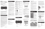
Fig. 1
Attach the wall plate to the wall.
(P) Concrete Anchor (x6)
6
(Q) M8x63 Hex Bolt (x6)
(R) Hex Bolt Washer (x6)
7
6.
7.
3.
Do not over-tighten the bolts and do not release the
wall plate until all screws are secure.
4.
Attach the cable manager to the middle of the top
crossbar (Fig. 2).
(S) Drill Bit (1)
Fig. 2
Attach the
cable manager
to the top
crossbar.
Fig. 4 - Use a longer bolt and spacer for displays with curved or recessed
backs. Do not use the M6 Washer (O) if you are using the M8 Bolts (J or K).
2.
Model No.___________________________________________
3.
Purchase Date:_______________________________________
Dealer/Address/Phone_ ________________________________
Before beginning the installation process, verify that you
have all the necessary tools on hand. The following tools
are required for proper installation:
1.
Important! Use extra
care during this part of the
installation. Avoid laying your
display face down if possible
as it may damage the viewing
surface.
Examine the back of your television. If the back of your
display is flat, you will be using one of the shorter bolts
from the hardware kit. If the back of your display is
curved or recessed, you will be using one of the longer
bolts and a spacer (Fig. 4).
For displays with flat
backs...
(L) M8 Lock Washer (x4)
Keep your sales receipt to obtain warranty parts and
service and for proof of purchase. Attach it here and record
the model number. This number is located on the product.
Preparing to install
Final Installation and
Adjustment
Remove the wall plate and drill a 1/4“ (6 mm) pilot hole
at each location using an electric drill.
(K) M8x40 Bolt (x4)
10.We recommend you hire a professional installer,
if you have any concerns about installing the TV
wall mount yourself.
2.
(J) M8x16 Bolt (x4)
Hire a licensed electrician to relocate an electrical
outlet, if needed.
Be sure to purchase wires long enough to connect
the TV to the audio and video components in your
installation.
1.
(G) M6x12 Bolt (x4)
4. Follow all instructions and recommendations regarding
Mounting the wall plate
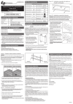
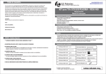
Product diagram
4.
Adjustment Knobs
1.
2.
Tools
#3 bit Phillips screwdriver
3.
Stud finder
Electric drill
Drill bit (included)
4.
5/16" (8mm) masonry drill bit for concrete/
brick installation
Level (integrated level on product)
5.
Hammer (for concrete installations)
Security Lock Position
To adjust the tilt position, have one person hold the
display in position while another person loosens the
two tilt adjustment knobs located on either side of
the wall plate (Fig. 7). Once the knobs are loose, move
the display to the desired angle. Re-tighten the knobs
before releasing the display.
Determine the correct diameter bolt to use by trying
one bolt each from Bags 1 - 4 of the hardware kit. Do
not force any of the bolts – if you feel resistance stop
immediately to avoid damaging your display.
Fig. 7
Loosen the
adjustment knobs
to change the tilt
angle. There is one
knob on each side
of the mount.
Attach the arms to the back of your display
using the bolts identified in Steps 1 and 2 and the
corresponding Lock Washer (C, F, I, or L) (Fig. 4). You
will need to use the M6 Washers (O) if you are using
the M4, M5, or M6 bolts. If your display has a curved or
recessed back, you may also need to use a Spacer (M or
N).
Make sure the screws are snug, but do not over-tighten.
Concrete/Brick Installation
Integrated Bubble Level
Padlock Hole
(padlock not
included)
The cable manager can be used to keep your power
cord and other A/V cables in order.
6.
TV Mount Plate
Wall Mount Plate
7.
Place the wall plate against the wall and level it using
the bubble guide.
With the help of another person, mark off six (6)
locations for fixing the mount to the wall.
Specifications
Model:
MAF70BK
Two-piece, low-profile design
Insert one Concrete Anchor (P) into each hole. A
hammer can be used to lightly tap the anchors into
place if necessary.
TV Size Range:
23" – 37"
With the help of another person, replace the wall
plate and level it using the bubble guide. Fix it to the
wall using the Lag Bolts (Q) and Lag Bolt Washers (R)
provided (Fig. 1).
Tilt:
Place the wall plate aside and drill a hole at each
location using a 5/16” (8 mm) masonry bit. Remove any
excess dust from the holes.
Do not over-tighten the screws and do not release the
wall plate until all screws are secure.
Attach the cable manager to the middle of the top
crossbar (Fig. 2).
Description:
Maximum Load:
Minimum Profile:
RCA Universal Flat Panel TV
Wall Mount
88 lbs. (39.9 kg)
3.1" (7.9 cm)
+/- 0-15°
Universal VESA Compatibility
Integrated Bubble Level
Cord Management
Medidas de Seguridad
Siga estas medidas para garantizar una instalación y
montaje seguros de su TV de panel plano.
1. Asegúrese de leer y entender completamente estas
instrucciones antes de intentar llevar a cabo la
instalación. Si tiene preguntas o dudas acerca de la
instalación, comuníquese con un instalador profesional
para solicitar asistencia.
Montaje en Pared para TV de LCD
Manual de Instalación
2. La pared o superficie de montaje deberá poder
Se ajusta a televisores de 23 pulg. a 37 pulg.
Capacidad máxima de carga – 39,9 kg (88 lb)
sostener el peso combinado del montaje en pared y
de la pantalla; de lo contrario, deberá reforzarse la
estructura.
3. Deberá utilizar gafas protectoras y herramientas
adecuadas. Se necesita un mínimo de dos personas
para llevar a cabo la instalación. Si no utiliza
vestimenta de seguridad y/o intenta llevar a cabo
esta instalación sin la ayuda de otra persona, podría
ocasionar daños a la propiedad, lesiones graves o
incluso la muerte.
Contenido del Paquete
Bolsa
núm.
(Ref.) Artículo (Ctd.)
1
MAF70BK
Thank you for choosing the RCA MAF70BK Universal
Gracias por elegir el Montaje en Pared Universal para TV
de Panel Plano MAF70BK de RCA. Este montaje puede
utilizarse con todas las principales marcas de televisores
de panel plano de 23 pulg. a 37 pulg., 39,9 kg (88 lb) o
menos. Este montaje en pared puede inclinarse de 0 a 15
grados para facilitar la visualización. Antes de intentar
montar su aparato de televisión, extraiga todas las piezas
de este paquete y lea las instrucciones de instalación
cuidadosamente.
ADVERTENCIA: El uso de este montaje con un televisor
de más de 39,9 kg de peso, o con una pantalla mayor de
37 pulg., podría ocasionar su fallo además de daños a la
propiedad y/o lesiones personales.
3
(H) PERNO M6x35 (X4)
(I) Arandela de seguridad M6 (X4)
Garantía Limitada Durante
la Vida Útil del Producto
Audiovox Electronics Corporation (la "Compañía") le garantiza a usted,
el comprador original de este producto que si, bajo condiciones y uso
normales, se encontrara que presenta defectos materiales o de mano de
obra durante su vida útil mientras sea de su propiedad, tales defectos
serán reparados o reemplazados (a opción de la Compañía) sin cargo
alguno por las piezas y labores de reparación.
Para obtener los servicios de reparación o reemplazo dentro de los
términos de esta Garantía, el producto se entregará con prueba
de cubierta de garantía (por ejemplo, factura fechada de venta),
especificación de los defectos, transporte prepagado, a la Compañía a la
dirección indicada abajo. No devuelva este producto al Distribuidor.
Esta Garantía no cubre un producto adquirido, mantenido o utilizado
fuera de los Estados Unidos o Canadá.
Esta Garantía no es transferible y no incluye los costos incurridos en la
instalación, remoción o reinstalación de este producto. Esta Garantía no
aplica si, es opinión de la Compañía que, este producto ha sufrido daños
debido a alteraciones, instalación inadecuada, abuso, uso indebido,
negligencia o accidente.
EL ALCANCE DE LA RESPONSABILIDAD DE LA COMPAÑÍA
BAJO ESTA GARANTÍA ESTÁ LIMITADO A LA REPARACIÓN O EL
REEMPLAZO PROVISTO ARRIBA Y, EN NINGÚN CASO, DEBERÁ
LA RESPONSABILIDAD DE LA COMPAÑÍA EXCEDER EL PRECIO DE
COMPRA PAGADO POR EL COMPRADOR DE ESTE PRODUCTO.
Esta Garantía reemplaza cualesquiera otras responsabilidades o
garantías expresas. CUALESQUIERA GARANTÍAS IMPLÍCITAS,
INCLUYENDO CUALQUIER GARANTÍA IMPLÍCITA DE
COMERCIABILIDAD O ADAPTABILIDAD PARA UN PROPÓSITO
EN PARTICULAR ESTARÁN LIMITADAS A LA DURACIÓN DE
ESTA GARANTÍA. EN NINGÚN CASO LA COMPAÑÍA SERÁ
RESPONSABLE POR DAÑOS EMERGENTES O INCIDENTALES.
Ninguna persona ni representante está autorizado a asumir, a nombre
de la Compañía, ninguna responsabilidad salvo la expresada aquí en
conexión con la venta de este producto.
Algunos estados/provincias no permiten limitaciones sobre la duración
de una garantía implícita o la exclusión o la limitación de daños
incidentales o emergentes, de modo que es posible que las limitaciones o
exclusiones anteriores no apliquen en su caso. Esta Garantía le confiere
derechos legales específicos; según el estado/provincia, puede disfrutar
además de otros derechos.
EE.UU.: Audiovox Electronics Corporation, 150 Marcus Blvd.,
Hauppauge, New York 11788
CANADÁ: Audiovox Return Center, c/o Genco, 6685 Kennedy Road,
Unit 3, Door 16, Mississauga, Ontario L5T 3A5
Marcas Registradas.
Todas las demás marcas y nombres de productos son marcas
comerciales o marcas registradas de sus respectivos dueños.
© 2008 Audiovox Accessories Corporation
111 Congressional Blvd., Suite 350
Carmel, IN 46032
www.rca.com
2. Coloque la placa de pared contra la pared y nivélela con
el nivel de burbuja.
3. Marque cuatro ubicaciones (dos por birlo) en la pared
donde se asegurará el montaje. Tenga a bien utilizar el
centro de cada birlo.
5. Con la ayuda de otra persona, vuelva a colocar la placa
de pared y nivélela utilizando un nivel de burbuja.
Fíjela a la pared utilizando los Pernos de fijación (Q) y
las Arandelas para pernos de fijación (R) suministrados
(Fig. 1).
1.
5
(P) Anclaje para concreto (X6)
Revise la parte posterior del televisor. Si la superficie
posterior de la pantalla es plana, deberá utilizar uno de
los pernos más cortos incluidos en el juego de herrajes.
Si la superficie posterior de la pantalla es curva o en
relieve, deberá utilizar uno de los pernos más largos y
un separador (Fig. 4).
2.
Mueva la lengüeta de seguridad de cada brazo a
su posición para evitar que la pantalla se separe
accidentalmente del montaje. Puede insertarse un
candado en una de las lengüetas para ayudar a evitar el
robo de la pantalla (Fig. 6).
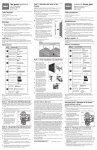
Fig. 6
Puede utilizarse un
candado pequeño
para ayudar a evitar
el robo de la pantalla
(candado no incluido).
Para pantallas con superficies
posteriores curvas o en relieve…
6
(Q) Perno hexagonal
M8x63 (X6)
(R) Arandela hexagonal (x6)
7
Fig. 1
Fije la placa de pared a la pared
6.
3.
4.
No apriete los pernos demasiado y no suelte la placa de
pared hasta que todos los tornillos estén asegurados.
7. Fije el control del cable al centro del travesaño superior
(Fig. 2).
(S) Broca 1
Fig. 2
Fije el control
del cable al
travesaño
superior.
Fig. 4 - Utilice un perno más largo y un separador para pantallas con
superficies posteriores curvas o en relieve. No utilice la Arandela M6 (O) si
está usando Pernos M8 (J o K).
2.
3.
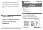
Diagrama del producto
4.
Perillas de ajuste
Instalación en Concreto/Ladrillo
1.
Coloque la placa de pared contra la pared y nivélela con
el nivel de burbuja.
Prepárese para la Instalación
2. Con la ayuda de otra persona, marque seis (6)
Antes de dar inicio al proceso de instalación, asegúrese
de tener todas las herramientas necesarias a la mano. Para
llevar a cabo una instalación adecuada, necesitará las
siguientes herramientas:
3. Coloque la placa de pared a un lado y perfore
ubicaciones para fijar el montaje en la pared.
un orificio en cada ubicación con una broca para
albañilería de 8 mm (5/16 pulg.). Remueva todo exceso
de polvo de los orificios.
4. Inserte un Anclaje para concreto (P) en cada uno de
los orificios. Puede utilizar un martillo para golpear
suavemente los anclajes en su posición, de ser
necesario.
Herramientas
Destornillador Phillips con punta #3
Buscador de birlos
Nivel (nivel integrado en el producto)
Fi 5
Fig.
Enganche cuidadosamente
la pantalla en la placa de pared.
(O) Arandela M6 (X4)
Nivel de burbuja integrado
Broca para albañilería de 8 mm (5/16 pulg.) para
instalación en concreto/ladrillo
precavido durante esta parte de
la instalación. De ser posible,
evite colocar la pantalla
boca abajo ya que esto puede
ocasionar daños a la superficie
de visualización.
(N) Separador grande (X4)
Núm. de modelo_ ____________________________________
Broca (incluida)
¡Importante! Sea sumamente
Para pantallas con superficies
posteriores planas…
Guarde el recibo como prueba de su compra y preséntelo
para obtener repuestos o solicitar servicio bajo garantía.
Anéxelo aquí y anote el número de modelo. Este número se
encuentra en el producto.
Taladro eléctrico
Con la ayuda de otra persona, levante cuidadosamente
la pantalla y colóquela en la placa de pared (Fig. 5). ¡No
suelte la pantalla hasta que los brazos de montaje hayan
enganchado completamente en los travesaños!
orificio piloto de 6 mm (¼ pulg.) en cada ubicación.
profesional, si tiene preguntas o dudas respecto a la
instalación del montaje en pared del TV.
Distribuidor/Dirección/Teléfono_________________________
1.
4. Retire la placa de pared y, con un taladro, perfore un
10. Le recomendamos contratar a un instalador
Fecha de Compra_____________________________________
Instalación y Ajuste Finales
(M) Separador pequeño (X4)
toma de corriente eléctrica, de ser necesario.
Martillo (para instalaciones en concreto)
MAF70BK_US_IB_00
Con un buscador de birlos, ubique y marque dos birlos
adyacentes para asegurar el montaje.
(L) Arandela de seguridad M8 (X4)
8. Contrate a un electricista autorizado para reubicar una
para conectar el TV a los componentes de audio y video
en su instalación.
Fig. 3
Fije los brazos a la parte
posterior de la pantalla.
(K) Perno M8x40 (X4)
pared esté fijada a los birlos de la pared. (Utilice un
buscador de birlos.)
9. Asegúrese de adquirir cables lo suficientemente largos
1.
(J) Perno M8x16 (X4)
4
Fije los Brazos al TV
asegurarse a dos birlos de madera adyacentes a una
distancia no menor de 41 cm.
(G) PERNO M6x12 (X4)
6. Es sumamente importante que la placa de montaje en
se ha incluido para garantizar un montaje seguro y
eficaz.
¡Importante! Por su seguridad, este montaje debe
(F) Arandela de seguridad M5 (X4)
5. Antes de dar inicio al proceso de instalación, asegúrese
7. Utilice el herraje incluido para el montaje. Este herraje
(B) PERNO M4x30 (X4)
(E) PERNO M5x30 (X4)
Asegúrese de haber adquirido el montaje en pared
correcto para su TV. Vuelva a verificar las restricciones
de tamaño y peso.
de tener todas las herramientas necesarias a la mano.
Necesitará un destornillador Phillips de punta #3, un
taladro eléctrico, una broca (incluida), un nivel (nivel
integrado en el producto), un buscador de birlos y un
martillo (para instalaciones en ladrillo y concreto).
Instalación en Pared de Yeso
(D) PERNO M5x12 (X4)
4. Siga todas las instrucciones y recomendaciones
referentes a ventilación apropiada y ubicaciones
adecuadas para el montaje de la pantalla en el manual
de instrucciones de su pantalla.
(A) PERNO M4x12 (X4)
(C) Arandela de seguridad M4 (X4)
2
Monte la placa de pared
Orificio para
candado (candado
no incluido)
Posición de bloqueo
de seguridad
5. Con la ayuda de otra persona, vuelva a colocar la placa
Placa de montaje
del TV
Placa de montaje
en pared
de pared y nivélela utilizando un nivel de burbuja.
Fíjela a la pared utilizando los Pernos de fijación (Q) y
las Arandelas para pernos de fijación (R) suministrados
(Fig. 1).
6. No apriete los tornillos demasiado y no suelte la placa
de pared hasta que todos los tornillos estén asegurados.
7. Fije el control del cable al centro del travesaño superior
(Fig. 2).
El control del cable puede utilizarse para mantener el
cordón de alimentación y demás cables A/V ordenados.
Para ajustar la posición de inclinación, haga que una
persona sujete la pantalla en posición mientras otra
persona afloja las dos perillas de ajuste de inclinación
ubicadas a ambos lados de la placa de pared (Fig. 7).
Una vez aflojadas las perillas, mueva la pantalla al
ángulo deseado. Vuelva a apretar las perillas antes de
soltar la pantalla.
Determine el perno de diámetro correcto que deberá
utilizar probando cada uno de los pernos incluidos
en las Bolsas 1 a 4 del juego de herrajes. No fuerce
los pernos – si siente algo de resistencia deténgase
inmediatamente para evitar ocasionar daños a la
pantalla.
Fig. 7
Afloje las perillas
de ajuste para
cambiar el ángulo
de inclinación.
Encontrará
una perilla
a ambos lados
del montaje.
Fije los brazos a la parte posterior de la pantalla
utilizando los pernos identificados en los Pasos 1 y 2,
y la Arandela de fijación correspondiente (C, F, I o L)
(Fig. 4). Si utiliza los pernos M4, M5 o M6, deberá usar
las Arandelas M6 (O). Si la superficie posterior de la
pantalla es curva o en relieve, deberá utilizar además
un Separador (M o N).
Asegúrese que los tornillos estén ajustados, pero no los
apriete demasiado.
Especificaciones
Modelo:
MAF70BK
Diseño de dos piezas, bajo perfil
Gama de tamaños de TV:
23 pulg. – 37 pulg.
Descripción:
Capacidad máxima:
Perfil mínimo:
Inclinación:
Montaje en Pared Universal
para TV de Panel Plano RCA
39,9 kg (88 lb)
7,9 cm (3,1 pulg.)
+/- 0-15°
Compatibilidad VESA universal
Nivel de burbuja integrado
Control del cordón