1
E-Power
e-MM/MT 230V
Manual De Instalación
User Manual
made in Italy
/620030202 Rev.1
Istruzioni-epower-25032015 (Cod.620030202 Rev. 1)EsEng.doc
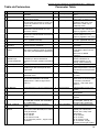
Index
Advertencia
Warning ........................................................................................................... 3
Guía del comprador
Guide to purchase .............................................................................. 4
Suministro y contenido Package contents .......................................................................... 5
Guía rápida de arranque Start Up procedure ....................................................................... 5
Instalación hidráulica
Hydraulic Installation ....................................................................... 5
Installación elèctrica
Electrical Installation........................................................................ 5
Instalación Software
Software Installation ........................................................................ 6
Generalidades
General Remarks ...................................................................................... 9
Descripción del producto Product Description ..................................................................... 9
Condiciones de uso
Usage Condition .............................................................................. 9
Características Tècnicas - - Technical Features .................................................................. 11
E-power MM .......................................................................................................................... 11
E Power MT ........................................................................................................................... 11
Protección
Protections ..................................................................................................... 12
Funcionamiento y uso
Functioning and Use ................................................................... 13
Conexión hidráulica
Hydraulic installation ..................................................................... 13
Conexión eléctrica Electrical Connection .......................................................................... 15
Conexiones adicionales Additional connections.............................................................. 18
Conectar un flotador externo (nivel minimo) Dry running float Configuration ..................... 18
Configuración Relay
Relay Configuration ................................. 18
Configuración Booster (bomba ON/OFF)
Booster Configuration (ON/OFF pump) ......... 19
Configuración Multibomba Multipump Configuration .......................................................... 22
Master/Slave Configuración Master/Slave Configuration ................................................... 25
Menù
Software Menu ......................................................................................................... 28
Solución de problemas y mantenimiento Troubleshooting&Maintenance ...................... 28
Menu Avanzado
Extended Menu ....................................................................................... 32
Tabla de Parámetros
Parameter Table .......................................................................... 34
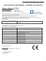
DECLARACIÓN DE CONFORMIDAD - CONFORMITY DECLARATION ................................ 37
2
Istruzioni-epower-25032015 (Cod.620030202 Rev. 1)EsEng.doc
Advertencia
Warning
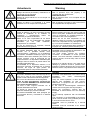
PELIGRO
Riesgo de lesiones personales y materiales si no
se cumple con los requisitos
DESCARGA ELÉCTRICA
Riesgo de choque eléctrico si no se cumple con
los requisitos
ADVERTENCIA
Riesgo de daños a la propiedad o el medio
ambiente si no se cumple con los requisitos.
DANGER
Risk of personal injury and property if not
complied with the requirements
ELECTRIC SHOCK
Risk of electrical shock if not complied with the
requirements
WARNING
Risk of damage to property or the environment if
not complied with the requirements.
ADVERTENCIA
Antes de instalar y de usar el producto lea este
manual de instalación en su totalidad. La
instalación y mantenimiento deben ser
realizados por personal calificado.
Mac3 no se hace responsable de los daños
causados por un uso inadecuado del variador
EPOWER
por
una
mala
instalación,
manipulación no autorizada.
El uso de refacciones no orginales, anularía
automáticamente la garantía.
ADVERTENCIA
El variador EPOWER debe ser instalado de
acuerdo con el apartado titulado como
“funcionamiento y utilización”. En la instalación
del variador EPOWER enfriado por agua, la red
hidráulica debe estar diseñada para evitar una
presión excesiva, como la provocada por los
golpes de ariete. Los dispositivos instalados para
proteger contra el exceso de presión deben ser
revisados periódicamente.
El EPOWER es un dispositivo eléctrico, si su
estructura mecánica es dañada por la presión
excesiva, las fugas de agua pueden ser
perjudiciales para los componentes eléctricos.
WARNING
Before installing and using the product read this
book in all its parts. Installation and maintenance
must be performed by qualified personnel in
accordance with current regulations.
MAC3 will not be held responsible for any
damage caused by improper or prohibited use
and is not responsible for any damages caused
by a not correct installation or maintenance.
The use of non-original spare parts, tempering or
improper use, make the product warranty null.
WARNING
EPOWER must be installed as described in the
paragraph “Functioning and Use”
You must project correctly the hydraulic
connection of EPOWER to avoid pressure
shocks. The shock absorber, installed to avoid
pressure shocks, must be keep under a correct
maintenance.
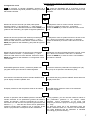
PELIGRO
El variador EPOWER está certificado bajo la CE,
pero en el caso de una incorrecta instalación
puede causar interferencias electromagnéticas.
En el caso de interferencia electromagnética,
antes de cada procedimiento, asegúrese de
que el variador EPOWER esté desconectado
de la fuente de alimentación.
No lleve a cabo ninguna maniobra con el
variador EPOWER encendido.
La puesta en marcha del variador EPOWER
debe ser realizada por personal calificado.
El variador EPOWER debe estar protegido por
un interruptor térmico y conectado a un sistema
de tierras.
DANGER
EPOWER is CE labelled but in the case of wrong
installation
can
cause
electromagnetic
interference.
Verify the correct operation of other electronic
devices with EPOWER on and running.
Malfunction of equipment can be harmful to
people and property.
In the case of electromagnetic interference
contact technical support and stop the plant.
Before any intervention censure that the
EPOWER is disconnected from the electricity
supply.
Do not attempt operations with the EPOWER
open
The connection of the EPOWER to the electric
panel must be carried out by qualified personnel
in accordance with current norms
EPOWER must be protected by a thermal
switch.
EPOWER must be connected to an efficient
earthing system
Epower is an electric device, if the case will be
damage by pressure shocks a possible water
infiltration could be dangerous due to the contact
between electric components and the water flow.
3
Istruzioni-epower-25032015 (Cod.620030202 Rev. 1)EsEng.doc
Guía del comprador
Guide to purchase
ES Gracias por su preferencia hacia nuestros productos, y
por elegir nuestro equipo. Considere la siguiente infomación
para utilizar e instalar correctamente su variador.
EN Thanks to have bought Epower! We would like to
notice some useful information to correctly use and
install EPOWER and the available accessories.
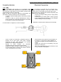
1. Selección de bombas: Con el fin de aprovechar
adecuadamente el funcionamiento del variador EPOWER
debe tener especial cuidado en la selección de la bomba. Un
variador EPOWER por su propia naturaleza acciona la
bomba a diferentes frecuencias con diferentes flujos de
demanda, logrando así alcanzar un alto ahorro energético y
un incremento en la vida útil de la bomba. Para obtener el
mejor comportamiento, debe elegir la curva correcta y una
bomba con características adecuadas (ver fig.), por lo
general las bombas centrífugas están diseñadas para poder
trabajar a diferentes frecuencias (bajo el mandato de un
variador EPOWER). La carga y caudal de la bomba debe ser
adecuados a las necesidades del sistema.
1. How to choose pump: to take advantage of
performance of EPOWER it is essential to choose the
correct pump.
The inverter pilots the pump on several frequencies
depending on the variation of flow. This is why it is
possible to save energy and to increase life time of the
pump.
For having correct behaviours it is essential to choose a
pump with slope characteristic curve (see fig.), usually
multiimpeller pumps; this kind of pump permits the
EPOWER to pilots pump at variables speed.
The head and capacity of the pump must correct for
request of the plant.
Head – H(m)
Flow – Q(m3/h)
2. Adaptador para conexiones de largas distancias
(ACL): El cable de conexión entre el variador EPOWER y
una bomba, puede crear un efecto capacitivo que afecte el
correcto funcionamiento entre el variador y la bomba. Para
cancelar la distorsión creada por el cable, MAC3 ofrece un
adaptador para las conexiones de gran longitud L> 15m,
hasta 80 metros. Este accesorio se utiliza generalmente en
aplicaciones con bombas sumergibles y se debe cotizar por
separado
3.Filtro EMI: Los variadores Mac3 están certificados con la
EMI para uso doméstico. Cuando se instala en un ambiente
especialmente
sensible
a
las
interferencias
electromagnéticas, MAC3 tiene a sudisposición filtros
EMI, los cuales se deben instalar entre el suministro de
voltaje y el variador EPOWER con el fin de eliminar
cualquier interferencia (se debe cotizar por separado).
2. Long Connection Adapter (LCA)The connection
cable creates, between EPOWER and pump, a
capacitive effect. For removing the disturbance Mac3
produces an adapter for long connection L>15mt (50
feet), up to 80 mt (260feet) of cable.
This device is normally used with submersible pumps in
well applications.
3.EMC filter: Mac3 inverters have domestic use EMC
approval.
If inverter is installed in enviroments particularly sensitive
to electromagnetic interference, Mac3 makes available
additional EMI filters, to be installed between the supply
and inverter, so as to eliminate.
4
Istruzioni-epower-25032015 (Cod.620030202 Rev. 1)EsEng.doc
Suministro y contenido
Package contents
ES Epower está integrado a un tubo de 1 ¼” y cuenta con
terminales de fácil montaje y cableado.
EN Epower is provided on metal pipe 1 ¼ "and easily
accessible terminals for wiring.
Guía rápida de arranque
Start Up procedure
Instalación hidráulica
Hydraulic Installation
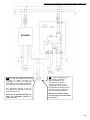
ES A continuación se presenta un diagrama a modo de
ejemplo sobre la correcta conexión del EPOWER en la red
hidráulica, para obtener más detalles e instrucciones,
consulte el apartado de “Uso y Funcionamiento”.
EN Hereafter a scheme, as example, for more details
and warnings see the section "Functioning and Use"
Installación elèctrica
Electrical Installation
ES Enseguida usted puede observar el diagrama típico de
conexiones para la alimentación al variador y a la bomba.
Para una información más detalla consulte el apartado de
“Uso y Funcionamiento”
EN Hereafter a scheme, as example, for more details
and warnings see the section "Functioning and Use”.
Bomba
Pump
Alimentación
Power Supply
Bomba
Pump
Alimentación
Power Supply
5
Istruzioni-epower-25032015 (Cod.620030202 Rev. 1)EsEng.doc
Instalación Software
Software Installation
Botón ON / OFF: para encender o
apagar el variador
ON/OFF button: to put on standby
the VFD
Botón SAVE/DISPLAY: para modificar o
visualizar algún parámetro.
SAVE/DISPLAY Button: to change and to
save the set value
Display 2 led
Botones de navegación + e – para
desplazarse sobre los parámetros.
Keys + and – scroll the parameters
and change the set values
Descripción de cada botón
Botón/Button
ON/OFF
SAVE/DISPLAY
+/-
Indicadores leds para cada valor mostrado en el
display.
Led indicators for the value shown on the display.
Led parpadeando de color rojo: indica
alarma.
Led flashing red: indicates alarm
Presión de la red
System Pressure
Presión de arranque
Restart pressure
Frequencia actual Frequency
Corriente de la bomba
Motor Current
Keyboard use
Acción
EFFECT
Permite encender o apagar la operación del
variador sobre la bomba.
To set the device in stand by and switch off
the pump.
- Mantener presionado por 5 segundos.
- Luz encendida: el variador está en operación.
- Luz apagada: el variador está apagado.
- Keep pressed for 5 seconds:
Light on: device is operating
Light off: device in stand by
Permite pasar del modo ajuste al modo de
supervision (Monitoreo).
It allows to switch from display mode to set
mode:
-Mantener presionado por 1 segundo para entrar al
modo de monitoreo.
-Mantener presionado por 5 segundos para entrar
en el modo de ajuste.
-Presione una segunda vez para grabar algún
valor y regresar al modo monitoreo.
Press for 1 second to see the value set
Si el led del botón SAVE/DISPLAY está encendido
de color verde, al presionar estos botones
podemos visualizar los valores de operación en
tiempo real de la bomba.
If LED SAVE / DISPLAY green: it Allows to
scroll through the parameters
Press for 5 sec. to enter into set mode
Press a second time to save the value and
return to display mode
If LED SAVE / DISPLAY red: it allows to
change the selected parameter value.
Si está encendido en color rojo, podemos modificar
el valor seleccionado.
6
Istruzioni-epower-25032015 (Cod.620030202 Rev. 1)EsEng.doc
Configuración inicial
Procedure
ES Al energizar el variador EPOWER, después de 2
segundos mostrará la siguiente pantalla: modelo y la version
del software utilizado.
EN Power the EPOWER and in 2 seconds it will be
displayed the model of the device and the version of the
software.
MM
01
Muestra el valor de corriente que usted podrá ajustar.
Presione el botón “+” para aumentar y “–” para disminuir
hasta obtener el valor deseado.Presione el botón SAVE para
grabar el valor deseado y para pasar al siguiente parámetro.
Displayed the value of current to be set. Press the +
button to increase the value and - to decrease.
Press the SAVE key to save the value and move to the
next.
6.8
Muestra el valor de la presión del sistema que usted podrá
ajustar. Presione el botón “+” para aumentar y “–” para
disminuir hasta obtener el valor desado. Presione el botón
SAVE para grabar el valor deseado y para pasar al siguiente
parámetro.
Displayed the value of System Pressure to be set. Press
the + button to increase the value and - to decrease.
Press the SAVE key to save the value and move to the
next.
3.0
Muestra el valor de presión de arranque que usted podrá
ajustar. Presione el botón “+” para aumentar y “–” para
disminuir hasta obtener el valor deseado. Presione el botón
SAVE para grabar el valor deseado. La configuración inicial
ha terminado.
Displayed the value of Restart Pressure to be set. Press
the + button to increase the value and - to decrease.
Press the SAVE key to save the value. The installation
procedure is finished.
2.6
El EPOWER graba los valores y muestra la palabra “OF”
(off) para indicar que la bomba no está energizada.
The device saves the parameters and displays OF (off).
the pump is not powered. activates the pump.
OF
Para activar la motobomba presione el botón ON/OFF hasta
que el display muestre la palabra “ON”.
To activate the pump push the ON/OFF button till the led
display shows ON..
ON
El display muestra el valor de presión actual en el sistema.
The LED display shows the value of the measured
pressure of system.
3.0
Durante la operación del EPOWER podemos visualizar los
valores sensados en los parámetros (presión del sistema,
presión de arranque, corriente consumida por el motor y
frecuencia a la cual el motor esta operando) presionando los
botones “+” y “-” . Para leer los valores de los parámetros,
presione el botón SAVE / DISPLAY por un segundo. El led
indica a que parámetro corresponde el valor visualizado.
During operation, you can read the measured values of
the parameters (pressure in the system, restart
pressure, current consumption of the pump and
frequency at which the pump is running) by pressing the
+ / - keys.
To read the values set of the parameters press the
SAVE / DISPLAY button for 1 second. The link between
the value displayed and the parameter is identified
accordingly by the LED flashing.
7
Istruzioni-epower-25032015 (Cod.620030202 Rev. 1)EsEng.doc
Sentido de rotación
En caso de necesitar que el motor invierta su sentido de giro
es posible hacerlo a través del menú extendido (ver
parámetro “Sentido de rotación”)
Rotation sense
In case of need to reverse the rotation sense of the
pump is possible to do so via software, entering the
extended menu (Parameter “Rotation sense”)
NB:
Para que el EPOWER esté configurado
correctamente después de la instalación, es
necesario hacer funcionar la bomba a la
velocidad máxima, durante al menos 60
segundos. De esta manera el EPOWER
almacenar el valor máximo de la potencia
absorbida por la bomba.
NB:
In order for EPOWER is configured
properly after the installation, you need
to work the pump at full speed for 60
seconds. In this way the EPOWER will
store the maximum value of the power
absorbed by the pump
8
Istruzioni-epower-25032015 (Cod.620030202 Rev. 1)EsEng.doc
Generalidades
ES Este manual ofrece la información esencial para la
correcta instalación, uso y mantenimiento del EPOWER.
Es muy importante que el usuario y/o instalador lea
cuidadosamente este manual antes de realizar cualquier
operación del equipo. Una instalación incorrecta puede
causar fallas o la anulación de la garantía.
Especifique siempre las siglas exactas del modelo, si se van
a solicitar información técnica o piezas de repuesto a
nuestras ventas y servicio post-venta.
Para instrucciones, situaciones y eventos que no están
cubiertos por este manual, póngase en contacto con el
servicio de post-venta.
General Remarks
EN This manual intends to provide essential information
for the installation, use and maintenane of the
EPOWER.
It is important that the user and/or installer carefully
reads the manual before installing and using the product.
Incorrect use may cause faults and result in the
annulment of the guarantee terms.
Always specify the exact identification of the model if
transit requests for technical information or spare parts
from our sales and service support.
In the event of instructions, situations and events not
contemplated in the present manual, please contact
technical customer support.
Descripción del producto
Product Description
ES . El EPOWER es un variador de frequencia enfriado por
agua para sistemas de presión constante.
EPOWER, regula automáticamente una bomba en función
de la necesidad de agua, regulando el número de ciclos del
motor.
.
EN
The EPOWER is a variable frequency drive
(inverter) for lifting units under constant pressure.
EPOWER, according to the actual water requirements
undertakes the automatic regulations of the number of
revs of the electro-pump whilst maintaining the system
pressure constant.
Epower està disponible en los siguientes modelos:
EPOWER-MM: variador enfriado por agua para,
alimentación monofásica para bomba monofásica.
EPOWER-MT: variador enfriado por agua para,
alimentación monofásica para bomba trifásica.
The Epower is available in the following versions:
EPOWER-MM: inverter water coooled, single-phase
line for single-phase pump.
EPOWER-MT: inverter water coooled, single-phase
line for three-stage pump.
Sistemas de presión con 2 bombas
Es posible configurar el EPOWER para controlar un
segundo motor a plena carga ON/OFF a velocidad fija
(bomba booster). Para una correcta instalación, siga las
instrucciones que aparecen en el diagrama de cableado
y se refieren a los "Enlaces adicionales". Mac3 ofrece
en su catálogo un tablero de control de la bomba ya
preparado para esta
Es posible configurar 2 EPOWER in configuración
Master/Slave
Una configuración multibomba (modelo ADVANCED)
está disponible para correr hasta 8 bombas.
La versión ADVANCED está compuesto por un
MASTER que los pilotos de hasta 7 SLAVES. El inverter
Master determina la función del sistema.
Pressurization groups
The Epower allows to drive a second pump ON/OFF
at a fixed rate (booster pump). For correct
installation, follow the wiring diagram and
instructions refer to paragraph “Additional
connections”. Mac3 has in the catalog a control
panel specifically design for this application.
N.B: La instalación debe ser realizadas por personal
calificado
NB: Installation must be performed by qualified
personnel
IMPORTANTE: Para esta aplicación se deben seleccionar
bombas con las mismas características: potencia motor (hp),
prevalencia (Hmax).
IMPORTANT: The pumps used must be of the same
characteristics: power engine (hp), head (Hmax).
Condiciones de uso
It’s possible to install the EPOWER in Master/Slave
configuration
A multipump configuration (ADVANCED model) is
available for running till 8 pumps.
The ADVANCED version is composed by a Master
that pilots till 7 Slaves.
The inverter Master determines the function of the
system.
Usage Condition
ES Temperatura de operación: 0°C ÷ +40°C
Máxima humedad: 50% a +40°C (sin condensación)
Temperatura lìquido: compresa tra +1°C e +40°C
Tipo de lìquido a bombear: agua libre de productos químicos
o residuos (ph 5÷9).
EN Operational temperature:0°C ÷ +40°C
Max.humidity: 50% at 40°C (no condensate)
Temperature of fluid: +1°C +40°C
Nature of fluid: water with no chemical add (ph 5÷9)and
no debris.
ADVERTENCIA
EPOWER debe ser instalado en ambientes que estèn
protegidos contra la congelación e intemperie. Se deben
dimensionar correctamente las conexiones hidráulicas de
WARNING
EPOWER must be installed in environments that are
protected from freezing and weather-proof.
You must project correctly the hydraulic connection of
9
Istruzioni-epower-25032015 (Cod.620030202 Rev. 1)EsEng.doc
EPOWER y su ubicación para evitar golpes de presión.
El tanque precargado, asì como elementos de protección de
la red hidráulica debe ser revisado periódicamente.
El EPOWER no debe trabajar con liquidos abrasivos,
sustancia solidas o fibrosas, asì como lìquidos inflamables o
explosivos
EPOWER to avoid pressure shocks. The shock
absorber, installed to avoid pressure shocks, must be
keep
under
a
correct
maintenance.
EPOWER cannot be used on pipes containing abrasive
liquids, fibrous solid substances or inflammable liquids or
explosives.
10
Istruzioni-epower-25032015 (Cod.620030202 Rev. 1)EsEng.doc
Características Tècnicas - - Technical Features
Frequecia de salida
5-100 hz
Output frequency
5-100 hz
Tiempo de aceleración
1,5 – 5 s
Acceleration time
1,5 – 5 s
Seguridad electrica
Compatibilidad
Electromagnètica
EN60730
EN61000-6-3
EN61000-6-4
Electrical safety
Electromagnetic
compatibility
EN60730
EN61000-6-3
EN61000-6-4
Display
2 digitos alfanuméricos
Display
2 digit alphanumeric
Posición de montaje
cualquiera
Assembly position
any
Presión de regulación
0,3 – 8 bar [4-116 psi]
Pressure to be set
0,3 – 8 bar [4-116 psi]
Max sobrepresión
12 bar [174 psi]
Max overpressure
12 bar [174 psi]
T de funcionamiento
5 - 40 °C
Operational Ta
5 - 40 °C
Grado de protección
IP65
Protection category
IP65
Entrada/Salida
1 ¼” macho
Input/output
1 ¼” male
Dimensioni
33 x 20 x 15 cm
Dimension
33 x 20 x 15 cm
Peso
2kg
Weight
2kg
1x230 Vac (da 170 a 270 Vca)
E-power MM
Power Supply
1x230 Vac (170 ÷ 270 Vca)
Potencia max. Bomba (P2)
230 Vac monofásico
1.1 kw (1.5 hp)
Max Pump Power (P2)
230Vac single phase
1.1 kw (1.5 hp)
Max. corriente de fase
8A
Max. Phase current
8A
Alimentación monofásica
1x230 Vac (da 170 a 270 Vca)
Monophase power supply
1x230 Vac (da 170 a 270 Vca)
Potencia max.Bomba (P2)
230Vac trifásica
2.2 kw (3 hp)
Max Pump Power (P2)
230Vac three-phase
2.2 kw (3 hp)
Max. Corriente de fase
10 A
Max. Phase current
10 A
Alimentación monofásica
E Power MT
11
Istruzioni-epower-25032015 (Cod.620030202 Rev. 1)EsEng.doc
Protección
Protections
ES . En caso de alguna anomalía el EPOWER apaga la
bomba y realiza intentos automáticos o programados para el
restablecimiento del sistema.
EN In the event of anomaly conditions Epower protects
the autoclave by switching off, but to ensure water,
attempts automatic or programmed reset operations.
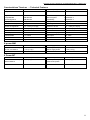
Tipo de protección
Restablecimiento
Bajo Voltaje
Automàtico (ver apartado de
Solución de problemas y
mantenimiento)
Automàtico (ver apartado de
Solución de problemas y
mantenimiento)
Intentos automáticos *.
Power voltage too low
Automatic (see “Troubleshooting
& Maintenance”)
Power voltage too high
Automatic (see “Troubleshooting
& Maintenance”)
Short circuit
Automatic attempts *
Intentos automáticos *.
Output current above
Automatic attempts *
threshold for over 1 min.
Automàtico (ver apartado de
Solución de Problemas u
Mantenimiento)
Intentos automáticos *.
Water temperature
above 75 °C
Automatic (see “Troubleshooting
& Maintenance”)
Automatic restart attempts *
Falta de agua o aire en Intentos automáticos *.
la tubería
Fallo del sensor
---
Insufficient pressure in
the system
Lack of water or air in
the pump
Pressure sensor fault
Golpe de ariete
Antibloqueo
(solo versión MM)
Pressure shock
Anti-lock
(only vers MM)
Automatic
If the pump is stopped for more
than 24 hours, the device restarts
the pump raising the pressure of
0.5 bar
Alto Voltaje
Cortocircuito
Corriente de salida
mayor del umbral
permitido durante más
de 1 minuto.
Temperatura del agua
por encima de 75 °C
Presión insuficiente
Intentos automáticos *.
Si la bomba es detenida por màs de
24 horas,el variador reinica la
bomba elevando la presión en 0.5
bares
Type of protection
Reset
n° programmable attempts**
---
*Nùmero programable de intentos para el restablecimiento
del sistema (programado de fábrica a 5 intentos).
* programmable number of automatic restart attempts factory default 5).
Si al terminar los intentos programados no se restablece el
servicio, es necesario hacer lo siguiente:
On exhausting the reset attempts you need to :
1. Desenergizar el EPOWER
2. Espere a que la pantalla se apague.
3. Energice de nuovo EPOWER.
1. disconnect power
2. wait for display to switch off
3. re-power
12
Istruzioni-epower-25032015 (Cod.620030202 Rev. 1)EsEng.doc
Funcionamiento y uso
Functioning and Use
Conexión hidráulica
Hydraulic installation
ES Epower puede ser instalado en cualquier posición. Sin
embargo, se recomienda la colocación vertical. En caso
necesita tener el dispositivo en posición horizontal, se
recomienda instalarlo con una ligera inclinación, a causa de
las secciones horizontales de tubería y simultáneamente con
bajo flujo de agua (3-5 litros / minuto), usted podría tener un
aumento significativo de la temperatura, que enviaría el
dispositivo en la protección.
EN Epower can be installed in any position. However,
we recommend the vertical positioning. In case you need
to have the device in a horizontal position, it is
recommended to install it with a light inclination, because
in horizontal sections of pipe and simultaneously with
low water flow (3-5 liters / minute), you could have a
significant increase in temperature, which would bring
the device in protection.
Precauciones:
Warnings:
-
-
Asegúrese de que la bomba esté perfectamente
cebada, antes de instalar el EPOWER.
Instale el EPOWER cerca de la bomba, si es directa la
instalación verifique no existan vibraciones que afecten
al EPOWER.
No utilice una tubería de descarga menor al diámetro
del EPOWER.
Evite lugares húmedos.
Instale un tanque precargado para proteger eI equipo
contra golpes de presión y continuos arranques con
demandas mínimas.
Ejemplo. del dimensionamiento del tanque de acuerdo a la
presión de trabajo:
Bomba 6 bar tanque 10bar
Ejemplo del dimensionamiento del tanque de acuerdo a la
bomba.
Bomba de 100LPM, tanque precargado de 10L (10%
del máximo flujo de la bomba).
La presión de precarga del tanque debe ser de un 80% de la
presión de trabajo del sistema.
Ejemplo.
Presión del sistema = 3bar (43 psi)
Presión de arranque = 2,6bar (37 psi)
Valor de precarga del tanque = (0,8 x 3) = 2,4bar
(34psi)
Si la presión de arranque es programada a más de 1bar
(14psi) sobre la presión de trabajo, entonces establezca el
80% de la presión de arranque.
Ejemplo.
Presión del sistema = 3bar (43 psi)
Presión de arranque = 2bar (29psi)
Valor de precarga del tanque = (0,8 x 2) = 1,6bar
(23.2psi)
Notas de instalación
- Se recomienda instalar una llave de pruebas.
- Insertar filtros en la red hidráulica para proteger que
sólidos en el agua dañen tanto a la bomba como al
EPOWER (Nota 1).
- Es necesario utilizar válvulas check en la red
hidráulica de acuerdo a la distancia y las características
de la red.
- Para facilitar el mantenimiento instale el EPOWER
utilizando tuercas unión.
- Instale una válvula de compuerta antes de la
conexión al tanque de precarga y un grifo cerca de
EPOWER para facilitar su mantenimiento.
-
-
Make sure pump is perfectly primed, before installing
EPOWER.
Install EPOWER near the pump; if installed directly
on the pump, verify that there are no harmful
vibrations.
Use tube diameter not less than those of EPOWER
attacks.
Avoid places where is possible precence of
condensation
Install an expansion tank to protect the product
against water hammer and to avoid continuous
restarting in presence of small losses.
Eg. Size, according to pressure of work:
Pump 6 bar expansion tank 10 bar
Eg. Size, in liters per minute according to the pump:
Pump 100lt/min expansion tank from 10lt/min
(10% of the maximum flow of the pump)
Preload value of the expansion tank should be about 0.8
x value of system pressure.
Eg.
System pressure = 3 bar
Restart pressure = 2.6 bar
value of precharge = (0.8 x 3) = 2.4 bar
If the restart pressure is at least 1 bar lower than the
system pressure, then the precharge value of the
expansion tank should be about 0.8 x pressure value of
restart pressure.
Eg.
System pressure = 3 bar
Restart pressure = 2 bar
value of precharge = (0.8 x 2) = 1.6 bar
Installation Notes
- Recommended to install a tap sampling.
- Insert a cartridge filter to protect both the system that
the device from impurities, always present in the
water (Note1)
- The inclusion of an external check valve is
mandatory.
- For easy maintenance, mount the drive using a 3piece union fittings
- Install a tap near the drive to facilitate the control of
the drive
- Install a gate valve in series with the expansion tank
for easy maintenance
13
Istruzioni-epower-25032015 (Cod.620030202 Rev. 1)EsEng.doc
Nota1: El agua en ocasiones contiene restos de sólidos, por tal motivo
es necesario colocar filtros para evitar que estos entren en la tubería y
ocasionen daños en el sistema de presión..
Diagrama de instalación hidráulica:
Note 1: The water always contains sand, iron, debris; such
impurities should not enter the hydraulic system because they
cause corrosion of pipes, damaging the equipment connected to
plumbing.
Water filtration for domestic use is required under the UNI-CTI
8065 and by decree of the Ministry of Health of 12.21.1990.
Installing a filter is not an option but a provision.
Hereafter a typical system diagram with surface
pump suction head:
14
Istruzioni-epower-25032015 (Cod.620030202 Rev. 1)EsEng.doc
Conexión eléctrica
Electrical Connection
(vers. MM)
ES El EPOWER esta provisto de 2 terminales (línea
/bomba) las cuales están disponibles al desatornillar la tapa
de conexiones, pase cada uno de los cables a través de los
prensacables provistos en esta tapa
Retire la tapa de conexiones, dejando al descubierto los
terminales y pasar los cables en sus prensacables:
Conecte el cable de salida (pump) a la bomba (2 fases
y tierra)
Conecte el cable de entrada (alimentación-2 fases y
tierra) a través de un interruptor de 2 polos de acuerdo
a la máxima corriente de la motobomba.
EN The device is provided with two terminals (line /
pump) accessible through a door with built-in cable
glands, which is connected to the device with screws.
Remove the door, exposing the terminal and passing the
cables in their cable glands:
Connect the output cable (ground, single phase)
to the pump
Connect the input cable (phase, neutral, ground)
to the single-phase line through a circuit breaker
sized according to the pump rating.
Hereafter an electrical link schema just for example.
A continuación un diagrama, a modo de ejemplo.
-
-
-
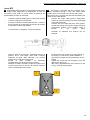
Cierre la tapa de conexiones, prestando atención a
posición de la junta tórica. Para evitar cualquier
infiltración de agua, debe adherirse a la correcta
posiciòn de montaje de la junta tórica..
Apretar
el
cierre
tornillos,
sin
apretarlos
completamente (ver la secuencia en la figura).
Después de haber acercado la tapa de conexiones a
la junta tórica sobre la puerta, de manera uniforme,
cerrar completamente los tornillos.
-
1
-
-
Close the door and ensure the correct position of
the O-Ring. To prevent any water infiltration is
necessary to respect the correct assembly of the
O-Ring.
Tighten the screws but not completely, using the
sequence in the figure.
After having approached the door uniformly on the
O-ring, continue to fully tighten.
3
2
4
15
Istruzioni-epower-25032015 (Cod.620030202 Rev. 1)EsEng.doc
(vers. MT)
ES El EPOWER esta provisto de 2 terminales (línea/bomba)
las cuales están disponibles al desatornillar la tapa de
conexiones, pase cada uno de los cables a través de los
prensacables provistos en esta tapa.
-
Conecte el cable de salida (pump) a la bomba (3 fases
-
y tierra) configuración () 230Vac
Conecte el cable de entrada (alimentación—3 fases y
tierra) a través de un interruptor de 2 polos de acuerdo
a la máxima corriente del variador
EN The device is provided with two terminals (line /
pump) accessible through a door with built-in cable
glands, which is connected to the device with screws.
Remove the door, exposing the terminal and passing the
cables in their cable glands:
Connect the output cable (ground, triple-phase,
-
A continuación un diagrama, a modo de ejemplo:
screen) to the three-phase pump with () triangle
configuration 230 Vac.
Connect the input cable with three wires (phase,
neutral and ground) to the power supply through a
single-phase 230Vac circuit breaker sized in
function
of
the
pump
rating.
Hereafter an electrical link schema just for
example.
-
-
Cierre la tapa de conexiones, prestando atención a
posición de la junta tórica. Para evitar cualquier
infiltración de agua, debe adherirse a la correcta
posiciòn de montaje de la junta tórica..
Apretar
el
cierre
tornillos,
sin
apretarlos
completamente (ver la secuencia en la figura).
Después de haber acercado la tapa de conexiones a
la junta tórica sobre la puerta, de manera uniforme,
cerrar completamente los tornillos.
1
4
-
-
Close the door and ensure the correct position of
the O-Ring. To prevent any water infiltration is
necessary to respect the correct assembly of the
O-Ring.
Tighten the screws but not completely, using the
sequence in the figure.
After having approached the door uniformly on the
O-ring, continue to fully tighten.
3
2
16
Istruzioni-epower-25032015 (Cod.620030202 Rev. 1)EsEng.doc
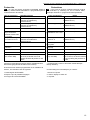
ES . EPOWER está certificado por:
EN60730 seguridad
EN61000-6-4 Las emisiones electromagnéticas industriales
EN61000-6-3 Las emisiones electromagnéticas
residenciales, con el cable de salida siguiente:
Longitud – Lenght
EN EPOWER is certified:
EN60730 safety
EN61000-6-4 EMC industrial environment.
EN61000-6-3 EMC residential environment, with the
following output cable:
Sección cable de salida - Section Output Cable
(cable blindado a tierra - Screen to GND)
2
1.5 mm
2m
ES Sección del cable de alimentación en función a la
distancia.
EN Section power supply cable linked to cable length.
Model MT- MM
S mm2
L max mt
1.5
20
2.5
50
Todas las partes internas del variador están
energizadas, en caso de contacto puede sufrir lesiones.
All internal parts of the drive are unde power
supply. In case of contact may sussit risk of death.
Toda instalación y/o mantenimiento deberá ser
efectuada por personal calificado, utilizando las herramientas
correctas y los equipos de seguridad adecuados. En caso de
algún fallo desenergice el variador.
All installation and maintenance work ,must be
performed by qualified staff using suitable instruments!
Staff must use suitable protective equipment.
In the event of a fault, disconnect or switch off the power
supply.
Antes de realizar cualquier modificación en el
cableado del variado espere al menos 5 minutos para que el
capacitor interno se descargue.
Peligro de electrocución, se corre el riesgo de sufrir lesiones
severas en caso de no seguir esta precaución.
Dispositivos de protección
Póngase en contacto con la compañía eléctrica de
suministro, para información sobre el equipo de protección
necesario.
Aplicable:
- Puesta a tierra de protección;
- Los dispositivos de protección con corriente residual CA y
CC (RCD);
- sistemas TN.
Puesta a tierra de protección
- Teniendo en cuenta la presencia de condensadores en el
filtro de entrada, es posible ocurrir corriente a tierra.
- Seleccionar una unidad de protección adecuado de
conformidad con las normas locales.
Dispositivo de corriente residual (RCD / RCCB)
- Cuando se utiliza un dispositivo de corriente residual
(RCD), su intervención debe ser seguro en caso de un
cortocircuito en la conexión CC a tierra del inversor!
=> Utilice RCD sensible a pulso de corriente
- Seleccionar a unidad de protección, de corriente residual,
adecuado de conformidad con las normas locales!
interruptor automático
- Utilice un disyuntor automático con curva característica tipo
C.
- Para el dimensionamiento de la seguridad de red, consulte
el capítulo Datos técnicos.
Before performing repairs on the drive wait at
least 5 minutes to allow the capacitor to discharge.
Danger of electrocution, burning or death if this
precaution is not observed.
Safety devices
Contact the electricity provider for information
concerning safety devices.
Applicable:
- safety earthing;
- safety devices operating with residue alternating and
direct current (RCD);
- TN systems.
Safety earthing
- Given the presence of condensers in the inlet filter,
current to mass may occur.
- Choose a suitable safety device according to local
regulations.
Residual current circuit breaker (RCD/RCCB)
- When a residual current circuit breaker (RCD) is used,
make sure it trips even if a short circuit occurs in the DC
part of the earth connection of drive!
=> use RCD's that are sensitive to pulse currents.
- Install the residue current circuit breaker according to
local bylaws!
Automatic switch
- Use an automatic circuit switch with a type-C
characteristic curve.
- Consult the Technical Specifications for the size of the
mains protection system.
17
Istruzioni-epower-25032015 (Cod.620030202 Rev. 1)EsEng.doc
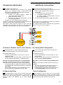
Conexiones adicionales
ES El variador está provisto de:
- Terminal de entrada para la conexión de un flotador
externo o un arranque remoto, si esta terminal está
programada, el EPOWER permanecerá en stand by.
- Terminal de salida relay, para:
1. controlar una segunda bomba a pilotar una
segunda bomba a frecuencia fija
2. activar una alarma externa.
3. Para crear un grupo de presurización con dos
ePower (Master/Slave)
Conexión con otros ePower (modo multipump)
La tapa de conexiones está diseñada para la perforación y la
inserción del cable para conexiones adicionales.
Para activar estas funciones ingrese al menú avanzado
"extended menu"(parámetro 50 active la operación de la
segunda bomba y parámetro 55 active el uso de flotador).
Additional connections
EN The internal terminals are provided of:
- Input for dry running floating or remote control. If this
input is enable, Epower is set in standby.
- Output relay:
1. To pilot a second pump at fixed rate
2. To activate an external alarm.
3. To create a group of pressurization with two
ePower (Master/Slave)
- Connection with other ePower (multipumps mode)
The terminal cover is designed for drilling and insertion
of the cable for the additional links.
To set these options enter in extended menu.(parameter
50 for 2nd pump and 55 for floating)
J11
J20
GALLEGGIANTE
FLOATSWITCH
Conectar un flotador externo (nivel minimo)
J10
Dry running float Configuration
ES Es posible utilizar un switch flotador externo para
detener la bomba al llegar a un nivel mínimo de agua.
EN You can use a float switch stop the pump at the
minimum water level.
Para habilitar esta función:
- Conecte el switch flotador en la terminal J11 (ver la
imagen de arriba)
- Habilite la función de control remoto "remote control" en
el menú extendido (parámetro 55 “Habilita remoto”).
Conectar una segunda bomba a plena carga (ON/OFF):
Es posible utilizar la terminal "relay run" para controlar el
arranque de una segunda bomba a plena carga (ON/OFF).
- La terminal puede ser usada para controlar un contactor
o un relevador del arrancador que gobierna la bomba a
plena carga.
- Para habilitar esta función vea los parámetros 50 y 51
del menú extendido estableciendo el valor “BO”.
To enable this function:
- Connect the floatswitch on the terminals J11 (see
picture above)
- Enable “remote control” function on extended menu
(par.55 paragraph Extended Menu)
Configuración Relay
Relay Configuration
ES Es posible utilizar el relé (J10) en la placa madre como
una señal de alarma, de bomba activa, o para construir el
sistema con una segunda bomba en frecuencia fija. Las
funciones pueden ser habilitado por el menú ampliado
(par.50).
EN It’s possible to use the relay (J10 ) on the mother
board as a warning signal, run pump, or to build boosting
system with a second pump at fixed rate.The functions
can be enabled by the extended menu (par.50).
EG. How to connect a second pump ON/OFF (fixed
rate)
You can use the RELAY RUN to pilot a second pump
ON/OFF.
- The relay can be used to operate a contactor or a
relay, with adequate power to drive the pump.
- Enable Booster function (see parameters 50 and 51
in the Extended Menu) setting the value “BO”
18
Istruzioni-epower-25032015 (Cod.620030202 Rev. 1)EsEng.doc
Configuración Booster (bomba ON/OFF)
ES
Conecte el control de BOOSTER en el terminal J10 entre
"C" y "NO". (Mira figura in párrafo “Conexiones
adicionales”).
Ajuste el parámetro 50: "Configuration.Relay" = "BO"
Ajuste el parámetro 51 "Inc Pres Booster" para aumentar
el valor de la presión (estandard = 0,2 bar). Este valor
determina el aumento en la presión del sistema requerida
después de arranque la bomba ON / OFF.
Booster Configuration (ON/OFF pump)
EN
Connect the control of booster on J10 between “C” and
“NO”.
Set parameter 50 : ”Configuration Relay” = “BO”
Set the parameter 51 “Inc Pres Booster” the value of
pressure rise (default = 0.2 bar). This value determines
the increase of the system pressure required after the
starting of the pump ON / OFF.
Booster Operation:
Booster Operación:
Modalidad de alimentación de la segunda bomba ON / OFF:
Cada vez que NO se alanza la presión del sistema y la
frecuencia del inversor ha llegado a la frecuencia máxima de
funcionamiento de la bomba (es.50Hz/60Hz), se acciona el
comando para arrancar la bomba ON / OFF.
Con la puesta en marcha de la segunda bomba se
incrementa la presión del sistema de un valor igual a la fijada
en el parámetro 51 "Inc Pres Booster" (por defecto 0,2
bar). Este parámetro determina el aumento en la presión del
sistema para evitar la oscilación. En caso de necesidad se
puede aumentar hasta un máximo de 1,5 bar (por defecto =
0,2 bar).
How to start second pump ON / OFF:
If the first pump cannot reach pressure system and the
frequency is at the maximum working value
(es.50Hz/60Hz), the drive switch on the command to
start the second pump ON / OFF.
As soon the second pump is started, the drive increase
the system pressure value by an amount equal to the
parameter 51 “Inc Pres Booster” (default 0.2bar [2.9psi]).
This parameter determines the increase of the system
pressure to avoid oscillation. In case of need can be
increased up to a maximum of 1.5 bar [21.75 psi]
(default = 0.2 bar [2.9psi]).
Modo de parada de la bomba Segunda ON / OFF:
El parámetro que desactivación a la segunda bomba es:
- parámetro 64 "umbral mínimo" (de fábrica = 50%)
Cuando el porcentaje de la potencia suministrada por el
variador está por debajo del umbral mínimo (par.64) y la
presión medida es mayor que la presión del sistema, a
continuación el comando desactiva la segunda bomba.
How to stop the second pump ON / OFF:
The parameter that switches off the control for the
second pump is:
-parameter 64 “MinTresholdPar” (default = 50%)
When the percentage of power is lower than the
threshold and the measured pressure is higher than the
system pressure, then the drive switches off the second
pump.
ES:
Parámetro 47 "Potencia del motor" = 1000 watts
parámetro 64 "Umbral Mínimo" = 50%
parámetro 72 "Press. del sistema" = 2,5 bar
Eg:
Parameter 47 “Motor Power” = 1000 watts
parameter 64 “MinTresholdPar” = 50%
parameter 72 “System Pressure” = 2.5 bar [36.26 psi]
Teniendo en cuenta los datos anteriores, la potencia para
desactivar la segunda bomba es 'igual a 50% de 1000 vatios
osea 500 vatios.
Si la presión medida es "mayor o igual a 2,5 bar y la potencia
medida es menor a 500 vatios, está, apaga la segunda
bomba.
The power value to switch off the second pump is equal
to 50% of 1000 watts then: 500 watts. So that if pressure
is greater or equal to 2.5 bar [36.26 psi] and power is
less than 500 watt the drive switch off the second pump
N.B. El Booster Configuración se activa sólo
cuando el modo de funcionamiento del inverter
es AUTOMÁTICO (consulte el parámetro 28 en el
menú ampliado)
N.B. The Booster configuration is only active
when the operating mode of the inverter is
AUTOMATIC (see parameter 28 in the
Extended Menu)
19
Istruzioni-epower-25032015 (Cod.620030202 Rev. 1)EsEng.doc
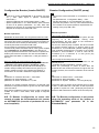
ES Ejemplo de conexión para el Modo Booster (bomba
ON / OFF - versión MM / MT)
EN Connection example for Mode Booster
(pump ON / OFF – MM/MT version)
EPOWER
ES En caso de mantenimiento del
Variador se puede conector un
presostato auxiliar que ppermite
garantizar la continuidad del servicio
en el sistema con la segunda bomba.
Se recomiendo preveer el uso de
una tanque de expancion adecuado
para esta apicacion.
Atencion: El presostatoauxiliar no
debe ser conectado cuando se
usa el variador.
ENIn case of maintenance of the
inverter, an auxiliary pressure
switch can be connected to
guarantee continuity of service to
the system with the on-off pump.
It is advisable to provide in this
case the use of an expansion
tank correctly dimensioned.
Beware the auxiliary switch
should not be connected when
the inverter.
20
Istruzioni-epower-25032015 (Cod.620030202 Rev. 1)EsEng.doc
EPOWER
ES En caso de mantenimiento del
Variador se puede conector un
presostato auxiliar que ppermite
garantizar la continuidad del servicio
en el sistema con la segunda bomba.
Se recomiendo preveer el uso de
una tanque de expancion adecuado
para esta apicacion.
Atencion: El presostatoauxiliar no
debe ser conectado cuando se
usa el variador.
ES En caso de mantenimiento del
Variador se puede conector un
presostato auxiliar que ppermite
garantizar la continuidad del servicio
en el sistema con la segunda bomba.
EN In case of maintenance of
the inverter, an auxiliary
pressure switch can be
connected to guarantee
continuity of service to the
system with the on-off pump.
It is advisable to provide in this
case the use of an expansion
tank correctly dimensioned.
Beware the auxiliary switch
should not be connected when
the inverter.
Se recomiendo preveer el uso de
una tanque de expancion adecuado
para esta apicacion.
Atencion: El presostatoauxiliar no
debe ser conectado cuando se usa
21
Istruzioni-epower-25032015 (Cod.620030202 Rev. 1)EsEng.doc
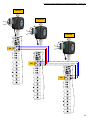
Configuración Multibomba
Multipump Configuration
ES Es posible conectar ePower en configuración multibomba
(sólo modelo AVANCED) compuesto de un inverter Master
que
puede
conducir
7
inverter
Slave.
EN It’s possible to connect ePower in multipumps
configuration (ADVANCED model only) composed from
an inverter Master that can drive 7 inverter Slave.
Para habilitar la configuración multibomba es necesario:
- quitar la tapa y abra uno de los agujeros colocados en la
cubierta. Utilizar un prensacable adecuado sobre el cable
para la conexión. Utiliza el terminal J20 terminal como en
“Ejemplo de conexión modo Master/Slave”
To enable mutipump mode is needed:
- Remove the lid and open one of the holes located in
the area of pre-drilling. Apply a cable gland of
adequate size for the type of cable used for the
connection between Master and Slave and connect
them using the terminals J20 see “Connection
between Master/Slave”.
- Set the parameter 28 “Next OpMpde” with the value
“MP”: Multipump.
- Set the parameter 4 “Net Config ID” with a number
between 0 and 7. The inverter with lowest numerical
value is the Master of the group.
- Set the parameter N. 47 “Motor Power” with the
nominal power value of the pump (P1). (See
parameter 47 in Extended Menu section). If in the
pump is shown only the useful power P2, the
nominal power is given by P2/0.7. For both the
power values (P1 and P2), the unit of measurement
is expressed in watts.
- After exiting from extended menu, the Master unit
displays "MA", while the Slave unit displays "Ux"
(where x is the number assigned to the inverter with
parameter 4).
- Configure el parámetro 28 "Próximo OpMode" con el valor
"MP": multibomba.
- Configure el parámetro 4 "Config red ID" con un número
entre 0 y 7. El inverter con el valor numérico más bajo esd
el Master del grupo.
- Establecer el parámetro 47 "potencia nominal" con el valor
de la potencia nominal de la bomba (P1). (sección Menú
extendido parámetro 47). En el caso que en la placa de la
bomba solo se encuentra la potencia de salida P2, insertar
como potencia nominal el valor del cálculo P2/0.7. Ambos
valores de potencia (P1 y P2) de la unidad de medida se
expresa en vatios.
- Después de salir del menú extendido, la unidad principal
muestra "MA" y la unidad Slave muestra "Ux" (donde x es
el número asignado al inversor con el parámetro 4).
Ejemplo de conexión in configuración Multibomba
Connection between Master/Slave:
22
Istruzioni-epower-25032015 (Cod.620030202 Rev. 1)EsEng.doc
ePower1
ePower2
ePower8
J20
J20
J20
23
Istruzioni-epower-25032015 (Cod.620030202 Rev. 1)EsEng.doc
N.B. Es posible utilizar sólo un flotador para
controlar el grupo en el modo multibombas:
ePower1
N.B. It’s possible to use only one floatswitch
to control the multipump group:
ePower2
ePower8
GALLEGGIANTE
FLOATSWITCH
24
Istruzioni-epower-25032015 (Cod.620030202 Rev. 1)EsEng.doc
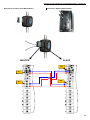
Master/Slave Configuración
Master/Slave Configuration
ES Con el fin de realizar un equipo con 2 bombas es muy
recomendable utilizar el modelo Epower Advanced en
configuración Multipumps.
Pero también se puede utilizar el modo master/slave que
permite conectar dos variadores en el mismo sistema para
aumentar la prestación del equipo de una manera
coordinada.
La secuencia para esta modalidad es a través de una línea
de comunicación ON/OFF usando el relé de salida y la
entrada digital disponible.
EN In order to realize a booster set with 2 pumps is
highly recommended to use the Advanced model il
Multipumps configuration.
But it is also possible to use the Master/Slave mode that
allows to connect two inverters on the same system in
order to improve its performance in a coordinated mode.
The connection for this mode is via a communication line
ON/OFF, using the output relay and the digital input
available.
N.B. No es posible utilizar al mismo tiempo
Master/Salve configuración y configuración
multibomba.
N.B. It’s not possible to use at the same
time Master/Slave configuration and
Multipump configuration.
Para activar esta función debe:
quitar la tapa y abra uno de los agujeros colocados en la
cubierta. Utilizar un prensacable adecuado sobre el
cable para la conexión entre maestro y esclavo;
conectarse mediante Terminal J10 y J11.
Ajuste el parámetro 50 "Configuración relé" con el valor
"MA" para la unidad Master y "SL" para la unidad
esclava.
(Véase el parámetro 50 en el menú
ampliado).
Establecer el parámetro 47 "potencia nominal"
con el valor de la potencia nominal de la bomba (P1).
(ver sección Menú extendido parámetro 47). En el caso
que en la placa de la bomba solo se encuentra la
potencia de salida P2, insertar como potencia nominal el
valor del cálculo P2/0.7. Ambos valores de potencia (P1
y P2) de la unidad de medida se expresa en vatios.
Ajuste parametro 64 "umbral inferior" en % del consumo
de energía absorbida que desconecta la bomba
controlada por los inversores de esclavo. (ver sección
Menú extendido parámetro 64).
Configuration:
- Remove the lid and open one of the holes located in
the area of pre-drilling. Apply a cable gland of
adequate size for the type of cable used for the
connection between Master and Slave and connect
them using the terminals J10 and J11.
- Set the parameter N. 50 “Configuration Relay” with
the value "MA" for the Master unit and "SL" for the
Slave unit. (See parameter 50 in Extended Menu
section)
- Set the parameter N. 47 “Motor Power” with the
nominal power value of the pump (P1). (See
parameter 47 in Extended Menu section). If in the
pump is shown only the useful power P2, the
nominal power is given by P2/0.7. For both the
power values (P1 and P2), the unit of measurement
is expressed in watts.
- Set the parameter N. 64 “Minimum threshold” with
the threshold in % of the absorbed power. The
inverter is turned off if the absorbed power of the
Slave unit is below the threshold (See parameter 64
in Extended Menu section).
Porque no es posible pasar parámetros de una máquina a
otra, los parámetros que intervienen en la configuración del
modo maestro/esclavo se deben establecer en los mismos
valores para ambos el inversor excepto párr. 50, que
determina si la unidad debe ser maestro o esclavo.
N.B. El Master/Slave configuración se activa sólo
cuando el modo de funcionamiento del inverter
es AUTOMÁTICO (consulte el parámetro 28 en el
menú ampliado)
The Master/Slave configuration mode is not a
system of passing parameters from one inverter to
another. The parameters involved in the
configuration of the Master/Slave mode must be set
to the same values for both inverters, except Par.50
that determines whether the unit must be Master or
Slave.
N.B. The Master/Slave configuration is only
active when the operating mode of inverter is
AUTOMATIC (see parameter 28 in the
Extended Menu)
25
Istruzioni-epower-25032015 (Cod.620030202 Rev. 1)EsEng.doc
Ejemplo de conexión modo Master/Slave:
Connection between Master/Slave:
MASTER
SLAVE
J11
J11
J10
J10
26
Istruzioni-epower-25032015 (Cod.620030202 Rev. 1)EsEng.doc
ES Calibración del sensor
Es importante que ambas unidades tengan el mismo valor
de la presión medida. Con el fin de obtener el máximo
rendimiento en la configuración del Maestro / Esclavo, por lo
tanto es necesario prestar especial atención a la calibración
del sensor de presión.
En caso de que sea complejo para alinear las presiones
medidas, también es posible para desalinear el valor de la
presión del sistema a fin de compensar el error:
EN Sensor calibration
It is important that both units have the same value of the
measured pressure. In order to obtain maximum
performance from the Master/Slave configuration is
therefore necessary to pay attention to the calibration of
the pressure sensor.
In case it is complex to align the measured pressures, it
is also possible to misalign the value of system pressure
to compensate the error:
Por ejemplo: Si la presión se mide desde el maestro es
2 bares y la presión medida por esclavo es 2,2 bar, significa
que 0,2 bar es la diferencia de presión entre las dos
unidades. Si quieres una presión del sistema de 2.5 bares,
se puede establecer:
For example, if the pressure measured by the MASTER
is 2 bar and the pressure measured by the SLAVE is
2.2 bar, it means that 0.2 bar is the difference pressure
between the two units. If is required a system pressure
of 2.5 bar, you can set the system pressure as follows:
-
Presión del sistema para el MAESTRO = 2.5 Bar
Presión del sistema para el ESCLAVO = 2,7 Bar.
-
(valor obtenido a través de: La presión del
sistema para el MAESTRO + diferencia de
presión medida entre MAESTRO
y
ESCLAVO)
ES Comunicación:
La
comunicación
características:
permite
apoyar
las
siguientes
System pressure MASTER = 2.5bar
System
pressure
SLAVE
=
2.7Bar.
(value obtained by: MASTER System
pressure + pressure difference measured
between Master and Slave).
EN Communication
The communication allows to support the two following
features:
• Activar unidad Esclavo
• Activación rotación de la unidad Master/Esclavo.
Activación de la unidad esclava se lleva a cabo
exclusivamente a través de la unidad Master. El intercambio
de funcionalidad de maestro/esclavo permite la rotación
entre los dos inversores, con el fin de distribuir la carga de
trabajo entre las dos unidades.
The Slave is activated only by the Master. The rotation
of Master/Slave allows to distribute the workload
between the two units.
Activation Slave unit
Rotation Master/Slave
27
Istruzioni-epower-25032015 (Cod.620030202 Rev. 1)EsEng.doc
Menù
Software Menu
ES . Utilice los botones de "+" y — para posicionarte en el
parámetro deseado, de acuerdo a la siguiente tabla.
Para cambiar el parámetro seleccionado, presiona el botón
de SAVE/DISPLAY por 5 segundos hasta que la luz
encienda en color rojo. Cambia el valor del parámetro
utilizando los botones de "+" y - . Guarde eI valor deseado
presionando el botón de SAVE/DISPLAY por 5 segundos. Se
recomienda consultar la siguiente sección para solucionar
problemas
Param
PRESSURE
PR.RESTART*
FREQUENCY
CURRENT
EN Use the + and – to select the desired parameter,
among those listed in the table, and read its value.
To change the selected parameter, press the SAVE /
DISPLAY button for 5 seconds, until the LED turns red.
Change the value of the parameter using the + and -.
Save the value by pressing for 5 seconds, the button
SAVE / DISPLAY. You should consult also the next
section for troubleshooting.
DESCRIPCIÓN
Muestra la presión de la red.
Se establece la presión de trabajo del sistema.
Muestra la presión de arranque.
Se establece la presión de re-arranque del sistema.*
Muestra la frecuencia a la cual gira la bomba.
Valor máximo de frecuencia del motor (no es posible
modificar este valor desde este menú).
Muestra la corriente consumida por la bomba.
Se establece la corriente máxima de la bomba.
La presión de arranque es definida por el Epower.
Presión de arranque = Presión de trabajo x 0.8.
Para modificarla, establezca el nuevo valor después de
ajustar la presión de trabajo del sistema.
Description
Displays the in pipe pressure.
Sets the required system pressure
Displays the restart pressure.
Sets the required restart pressure
Displays the instant pump frequency.
Max value set for the frequency (not
changeable in this menu)
Displays the current absorbed by the
pump.
Set the max rms value of the phase current
The restart pressure is calculated from Epower.
Press. Restart = Press. System x 0.8.
To change it, please set the new value after setting the
system pressure.
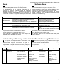
Solución de problemas y mantenimiento Troubleshooting&Maintenance
ES IEl Epower ofrece protecciones a la bomba contra
cualquiera delasfallas más comunes en una instalación
hidráulica. Para asegurar el suministro de agua en la
instalación
realice restablecimientos automáticos y
programables. El display muestra el mensaje y códigos de
error para identificar el tipo de fallo.
Cód.
Code
00
Mensaje
Message
Corto f-f
ShortC. F-f
EN The Epower provides pump protection from any type
of common problems and to safeguard the water supply
the drive attempts automatic restarts.
The display shows messages and error code to identify
the type of fault .
Falla
Solución
Se ha detectado un
corto circuito entre
fases o fase y tierra.
Se harán 5 intentos
de restablecimiento
automático, después
es necesario un
restablecimiento
manual..
Identifique el corto
circuito.
Compruebe el
consumo de
corriente de la
bomba.
Desconecte el
voltaje, espere que
se apague el
Display y conecte de
nuevo.
Message
meaning
Phase-Phase or
Phase-Ground
short circuit found.
5 Automatic
restarts and then
a permanent
locked status
Action required
Remove the short
circuit.
Check the correct
motor absorption.
Disconnect the power
supply.
Wait for the display to
switch off.
Restore the power
supply.
28
Istruzioni-epower-25032015 (Cod.620030202 Rev. 1)EsEng.doc
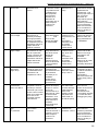
01
Fallo Max Corr
Imax Fault
Sobrecorriente
detectada en la
bomba.
Compruebe el valor
de corriente medido
en el parámetro 36.
Y establezca un
valor apropiado
como máxima
corriente en el
parámetro 49.
Compruebe que no
exista bloqueo o
fricción en los
impulsores.
Over current
detected in the
pump
02
Bajo voltaje
Low Voltage
Corrobore que el
voltaje del sistema
este
dentro de los
valores permitidos
por el EPOWER
03
Alto voltaje
High voltage
El voltaje de
alimentación es
sensado por debajo
del rango permitido
(menor a 170 VCA).
El restablecimiento es
automático cuando el
voltaje alcanza lo
svalores correctos.
El voltaje de
alimentación es más
alto de lo permitido
(mayor a 270Vac) El
restablecimiento es
automático cuando el
voltaje alcanza los
valores correctos.
Power voltage
measured is too
low (less than 170
Vac).
The reset is
automatic when
the voltage
returns to the
correct values
Power voltage
measured is too
high (over 270
Vac).
The reset is
automatic when
the voltage
returns to the
correct value
04
Alta temperatura
del líquido
High Temp.
La temperatura del
líquido es mayor a 75
°C. Restablecimiento
automático si la
temperatura < 60°C.
05
Bloqueo por
cortocircuito.
Short Circ.Block
El EPOWER está
bloqueado. Hará 10
intentos por reiniciar,
buscando que el corto
circuito a tierra o entre
fases se ha eliminado.
De no ser así es
necesario reiniciar
manualmente.
06
Pico de corriente
(I2t)
I2t protected
El Epower ha detecto
una excesiva
corriente.
Corrobore que el
voltaje del sistema
este dentro de los
valores del
EPOWER.
Verificar la
presencia de aire
dentro de la bomba
y, si es necesario
eliminarla.
Confirme que la
temperatura del
agua está dentro de
los parámetros
permitidos por el
EPOWER.
Control que la
bomba se ceba
correctamente
Para remover el
estatus de bloqueo,
coloque en cero el
número de
cortocircuitos en el
parámetro 65 “Total
de cortocircuitos
detectados”. Sí el
problema persiste
intente reinciar el
EPOWER
desconectando la
motobomba.
Compruebe que la
motobomba sea
usada de acuerdo a
su diseño y que no
exista bloqueo o
fricción en los
impulsores.
Check current
measurement output
at parameter 36
“LoadCurrent “ and
set the proper value of
max. current at
parameter 49.
Verify that the pump is
used under the
conditions prescribed
by its manufacturer
Make sure that there
are no conditions of
friction or locking of
the impeller
Check the electric
system and reset the
values to within the
range prescribed for
the EPOWER
Check the wiring
system and set the
values in the range
prescribed for the
EPOWER.
Check for the
presence of air inside
the pump and if
necessary eliminate it.
Water
Temp>75°C.
Automatic reset if
Temp.< 60 °C:
Check water
temperature is within
the values indicated in
the product
specifications.
Check and restore the
correct pump priming
action.
The drive is in
lock status after
10 reset attempts
made following
short circuit
between phase
and phase and
phase-earth on
the electro-pump.
To remove lock status
set to zero the
number of shortcircuit
parameter 65
“Tot.ShortC.Done “
If the problem persists
try to reset the drive
unplugging the pump .
The drive has
measured an
excessive current.
Verify that the pump is
used under the
conditions prescribed
by its manufacturer
Make sure that there
are no conditions of
friction or locking of
the impeller
29
Istruzioni-epower-25032015 (Cod.620030202 Rev. 1)EsEng.doc
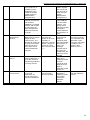
07
Motobomba
desconectada
Motor Unconnected
La motobomba no
esta conectada al
EPOWER
Corrobore que la
bomba está
conectada al
EPOWER
The pump isn’t
connected to the
inverter
10
Sin líquido
No water
Verifique:
- La presencia de
líquido.
- Que la motobomba
fue cebada de forma
correcta.
- Que el filtro no
está bloqueado.
- Desenergice la
alimentación del
voltaje.
Espere a que se
apague el Display y
energice de nuevo
Lack of water
found
Automatic reset
set in factory for 5
reset attempts
every 5 minutes; if
unsuccessful the
reset is again
attempted every
50 minutes for 24
times. After which
the system
remains in a state
of permanent
blockage.
11
Presión
insuficiente.
Insuff
Insuff. Pres
Falta de líquido
detectada,
restablecimiento
automático de
fábrica= 5 intentos
cada 5 minutos; sí no
se detecta líquido en
estos intentos, se
harán 24 intentos más
cada 50 minutos, si
después de esto no
se ha corregido la
falta de líquido, el
sistema requiere
reinicio manual.
La presión medida
está por debajo del
mínimo valor
permitido (de fábrica
0.8 bar /11 psi).
Restablecimiento
automático, 1 intento
cada 5 minutos, si no
se consigue
restablecer se harán
Z4 intentos, un intento
cada 50 minutos.
Después de esto el
sistema requiere
restablecimiento
manual.
Corrobore:
—Que no existan
fugas en la red
hiráulica.
—EI correcto
dimensionamiento
del sistema.
—Una vez eliminada
la falla, desenergice
el Epower, espere a
que se desenergice
el Display y energice
nuevamente.
12
Fallo del sensor de
presión.
Press Sensor Fault
Golpe de ariete.
Water Hammer
Se ha detectado fallo
en el sensor de
presión.
El sistema ha
detectado una
sobrepresión mayor a
2 veces la presión de
trabajo.
El restablecimiento es
automático. El
variador requiere
restablecimiento
manual después de 5
intentos.
La bomba ha estado
funcionando de forma
continua durante el
tiempo programado
en el par 40
El inverter está
configurado como
Maestro
Contacte a su
distribuidor.
The pressure
measured is
under the minum
set value (default
0,8 bar).
Automatic reset
set in the factory
for 1 reset attempt
every 5 minutes if
unsuccessful the
reset operation is
attempted again
every 50 minutes
for 24 times. After
which the system
is permanently
blocked
Detected a fault in
the pressure
sensor
The system
detected an
overrun of more
than 2 times the
pressure set. The
reset is automatic.
The drive is
blocked if the
number of
automatic restarts
is over 5.
The pump has
been in operation
continuously for
the time set in
parameter 40
The inverter is
configured like
Master
13
15
Protección bomba
Pump Protection
MA
Master
Verificar el correcto
dimensionamiento
del tanque
precargado.
Compruebe si hay
fugas en el sistema
El mensaje "MA"
puede visualizarse
cuando se utiliza el
inverter en
configuración
Master/ Slave
(grupo con 2
inverter) y en el
modo multibomba.
Check that the
power output cable
from the inverter is
connected to the
pump
Check for water
presence.
Reset the correct
pump priming
function.
Check that the filter is
not blocked.
Disconnect the power
supply.
Wait for the display to
switch off
Re-connect power
supply.
Check that there is no
major leakage on the
system
Check the correct
dimensions of the
electro-pump
On eliminating the
causes disconnect the
power supply
Wait for the display to
switch off
Restore power supply.
Contact after selling
service
Verify the correct
functioning of
expansion tank.
-Check the leaks of
the system
The message "MA"
can be displayed
when the inverter is
used in Master/Slave
configuration (group
with 2 inverter) and in
the multipump mode.
30
Istruzioni-epower-25032015 (Cod.620030202 Rev. 1)EsEng.doc
SL
Slave
Se utiliza el inverter
en un grupo con 2
unidades y se ha
establecido como
unidad secundaria
(véase la sección
"Master/Slave
Configuración”)
El Modo Multibomba
utiliza el protocolo de
comunicación
CANBUS. La pantalla
muestra "CB" cuando
un intercambio de
datos está presente
entre los inverter de
un grupo.
-
CB
CANBUS
ID
Error de
identificación
ID Error
En el modo
Multibomba el usuario
asigna un valor
numérico (ID) que
identifica el inverter en
un grupo. El mensaje
indica que el grupo
son inverter con el
mismo identificador
numérico.
Para eliminar el
error tiene que
cambiar en el menú
avanzado, el
parámetro 4 "Config.
Red ID" y asigne el
inversor un nuevo
valor numérico entre
0y7
Ux
Unidad “x”
Unit “x”
Identifica los Slave en
modo multibomba. "x"
es el valor numérico
asignado al parámetro
4 "Config. Red ID”
-
FS
Fuera servicio
Out of service
El mensaje aparece
en el modo
multibomba. El
inverter terminó los
reinicios automáticos.
-
Identificar la causa
de la anomalía y
reinicie el inversor
The inverter is
used in a group
with 2 units and
has been set as
slave unit (see
section
"Master/Slave
Configuration”)
Multipump mode
uses CANBUS
communication
protocol . The
display shows
"CB" when a data
exchange is
present between
the inverters in a
group.
In Multipump
mode the user
assigns a
numerical value
(ID) that identifies
the inverter in a
group. The
message
indicates that in
the group are
inverters with the
same numerical
identifier.
Identifies the
slave unit in
multipump mode.
"x" is the
numerical value
assigned to the
slave in
parameter 4 "Net
Config. ID "
The message is
displayed in
multipump mode.
The inverter
finished the
automatic
restarts.
-
-
To remove the error
you need to change
from extended menu,
parameter 4 "Net
Config.ID" and assign
to inverter a new
numeric value
between 0 and 7.
-
Find the cause of the
fault and restart the
inverter
31
Istruzioni-epower-25032015 (Cod.620030202 Rev. 1)EsEng.doc
Menu Avanzado
Extended Menu
I El menú avanzado nos permite la visualización de todos
los parámetros. Para acceder a este menú mantenga
presionados simultáneamente los botones "+" y "-“ por
algunos segundos.
Apareceran las letras "EX" y el número de parámetro.
EN The extended menu permits the visualization of all
parameters. To access to the parameter list keep the
keys: + and - , pressed simultaneously for a few
seconds. Displayed the initial EX and the parameter
number.
EX
01
Use the key + and - to select the desired parameter.
To view the parameter value press the SAVE / DISPLAY
key.
Eg choice of the parameter maximum frequency.
Utilice los botones de "+" y "-" para seleccionar el
parámetro deseado. Para visualizar el valor del parámetro
presiona el botón de AJUSTE/ MONITOREO. Ejemplo:
seleccione el parámetro de máxima frecuencia.
01
Para modificar el parámetro presiona el
AJUSTE/MONITOREO hasta que encienda la led.
Con los botones "+" y "-" coloque el valor deseado.
Ejemplo: para establecer 60 hz.
botón
To modify the parameter press the key SAVE / DISPLAY
until all the LEDs light up.
With the key + and - change the parameter value.
Eg lead to 60Hz, the maximum value.
60
Para guardar el nuevo valor, pulse nuevamente el botón
AJUSTE/MONITOREO hasta que aparezca EX y apagan
los leds; se regresa a la lista de los parámetros.
To save the new value press the key SAVE / DISPLAY
until it appears EX and the leds are off; you are back to
the parameter list.
EX
01
Para salir del menú avanzado presiona simultáneamente
los botones: "+” y "-”, hasta que las letras EX aparezcan
en el Display por algunos segundos, de esta manera los
nuevos valores serán guardados. Para salir sin guardar los
nuevos valores presiona el botón ON/OFF: los cambios no
serán guardados y se perderán al salir del menú.
Mostrar valores de los parámetros con más de 2 dígitos.
Valores de 4 dígitos: muestran alternadamente dos dígitos
de los valores más significativos (indicados por la presencia
de un punto al lado derecho).
Ejemplo: para el valor 1234.
To exit the extended menu simultaneously press the
keys +and -, until the EX is written on the display for a
few seconds; so that the changes will be saved in
memory.
To exit without saving the new value press the ON / OFF:
the changes made will not be saved and will be lost with
the shutdown of the device.
Value display for parameters of over 2 digits.
4-digit values: displayed alternate of the two most
significant digits (indicated by the presence of the right
point on the display) and the 2 least significant digits.
Eg 1234
12.
34
32
Istruzioni-epower-25032015 (Cod.620030202 Rev. 1)EsEng.doc
Valores de 3 dígitos: muestra alternadamente el dígitos
más significativo (indicado por la presencia de un punto al
lado derecho). Ejemplo: para el valor 234
3-digit values: displayed alternate of the most significant
digit (indicated by the presence of the right point on the
display) and the 2 least significant digits. Eg 1234
2.
34
Mostrar valores negativos: números mostrados después
del símbolo "-“ y el valor númerico.
Ejemplo —0.3
Display of negative numbers displayed alternate of the
sign - and the numeric value.
Eg -0.3
0.3
Para cambiar los parámetros con más de 2 dígitos, se
hace de la misma manera que el caso de parámetros de
sólo 2 dígitos. Pero cuando se presiona el botón "+" o "-" el
display muestra sólo los 2 valores menos significativos.
To change the value for parameters over 2-digits act as
in the case of parameters to 2-digits, but when pressing
the + or - button will display only the 2 least significant
digits.
33
Istruzioni-epower-25032015 (Cod.620030202 Rev. 1)EsEng.doc
Tabla de Parámetros
N. Nome
01 Frecuencia Max
03 Frecuencia Nomin.
04 Config. Red ID
06 Aceleración
07 Deceleración
08 Velocidad manual
11 Unidad de medida
14 Número de intentos
realizados
15 Pres. Golpe de
presión
18 Número de intentos
realizados por
alarmas hidráulicas
19 Duración perturb.
20 Golpe de ariete
21 Frec.Minima PID
22 Presion Minima
Parameter Table
Descrizione
Digit Name
Frecuencia máxima de salida del
2 Max frequency
EPOWER
Indica la frecuencia de operación
2 Nominal frequ.
máxima de la bomba.
Establece el identificador numérico para
2 Net Config ID
los inversores que forman un grupo. Se
requiere el parámetro sólo en el modo
Multibomba
Se establece el tempo de aceleración
2 Acceleration
para llevar la bomba desde cero a la
frecuencia máxima.
Se establece el tempo de deceleración
2 Deceleration
para llevar la bomba desde la frecuencia
máxima a cero
Establece la frecuencia aplicada al
2 Manual speed
motor: (opMode=manual).
Elija la unidad de medida
2 Unit measure
Muestra el número de intentos para
2 Drive Rst Done
restablecimiento realizadas.
Establece el valor máximo de presión
2* Shock Pressure
para activar la alarma "golpe de presión’.
Valor “NO” para desactivar la protección
Muestra el número de intentos
realizados por alarma hidráulicas
(ejemplo=no líquido, presión insuficiente,
etc).
Duración perturbación
Cuenta las veces que la presión medida
ha sido mayor dos veces que el valor
programado.
2
Autoc Rst Done
2
2
Perturb. Length
Water hammer
Frecuencia mínima de arranque y
parada del motor
Presión mínima del sistema, por debajo
del cual está señalada la anomalía
("baja presión" / "falta de agua" Error
Code:11).
2
PID Min. Fout
2* Min Pressure
25 Anti Bloqueo
Activar/desactivar la función antibloqueo
2
Antilock enable
26 PID KP
Coeficiente proporcional del regulador
PID
Coeficiente integral del regulador PID
2
PID KP
2
PID KI
Establece el modo de funcionamiento de
la unidad (MA: manual, AU: automático,
MP: multibomba)
Modo de funcionamiento actual del
variador
El parámetro contiene 3 alternativas
(“SL”=Lento,”NO”=Normale,”FA”=Veloz)
de los parametros:
par.26: PID KP,
par.27: PID KI,
par.45: Divisor T.PID,
par.19: Duración perturb.., según el tipo
de sistema.
2
Next OpMode
2
Present OpMode
2
Plant Response
27 PID KI
28 Proximo OpMode
29 Actual OpMode
30 Respuesta del
sistema
Description
Maximum frequency of drive
output
Sets the applicable frequency
on the motor to obtain Vmax
Sets numerical identifier to the
inverters of the group. The
parameter is used only in
multipump mode.
Sets the acceleration time to
move from null to maximum
frequency applied to the motor
Sets the deceleration time to
go from maximum to null
frequency applied to the motor
Sets the frequency applied to
the motor (OpMode=manual)
Set the unit measure
Displays restarts number
undertaken
-Sets the maximum pressure
to activate the alarm “Shock
Pressure”
-Sets “NO” to disable
protection
Displays the number of
restarts undertaken for
hydraulic alarms (i.e. dry
running, Insuff. Pressure)
Time length for perturbation
Counter events when the
measured pressure is found to
be double that of the pressure
setpoint
Minimal frequency applied to
the motor
Minimum system pressure,
under which an anomaly state
is indicated (“Insufficient
pressure” / “No water” Error
Code:11).
Enable/Disable the anti-lock
function
Proportional coefficient of the
PID regulator
Integral coefficient of the PID
regulator
Sets the operational mode of
the drive (MA: manual, AU:
automatic, MP: multipump)
Autoclave operational mode
The parameter contains 3
presets (“SL”=Slow,”NO”=
Normal,”FA”= Fast) of the
parameters:
par.26: PID KP,
par.27: KI PID,
par.45: Divisor T.PID,
par.19: Perturb. Length,
according to the type of plant.
34
Istruzioni-epower-25032015 (Cod.620030202 Rev. 1)EsEng.doc
31 Lectura sensor de
presión
32 Offset Sens.Press
Frecuencia leída desde el sensor de
presión
Offset de sensor de presión (presión
ambiental establecido = 0 bar)
33 Ganancia SensPress La calibración de la escala de la lectura
de la presión.
34 Presion Medida
Presión dedida del sistema
35 Tension de ingreso
Tension de alimentacion del EPOWER
36 Corrente de salida
Corrente de fase del motor
37 Temperatura Drv
Temperatura medida sobre el modulo de
potencia
40 MaxTiempoBombaON Establece el tiempo máximo (en
minutos) de trabajo continuo de la
bomba.
Después de la hora establecida,
aparecerá la advertencia "Protección de
la bomba" spreader es excluir el ajuste
de protección "NO"
41 MaxTiempoP.Insuf.. Tiempo para entrar en estado de "baja
presión"
43 MaxTiempo NoAgua Tiempo para entrar en estado "Falta de
agua"
44 Tempo DeltaBar
Rango de interrupción cuando la presión
y la frecuencia son constantes
45 Divisore T.PID
Disminuye la velocidad de respuesta
del sistema a los cambios en la presión:
se utilizará cuando el sistema es
inestable '(por ejemplo, las oscilaciones
de presión, continuación)
46 Freq.Motore (Hz)
Frecuencia aplicada al motor
47 Potencia del Motor
Establece la potencia nominal del motor
P1
Visualiza la potencia absorbida por la
bomba (P1)
Valor máximo de la corriente de fase del
motor.
48 Potencia Motor
49 MaxCorr.Motor
50 Configuracion Relay
Selección de la funcionalidad del relé:
AL = Alarma,
RU = Marcha,
BO = Booster,
MA = Maestro,
SL = Slave
51 Incremento Presion
Booster
Aumento de la presión del sistema
cuando modalidad booster es
activa(default 0.2 bar)
Establece el pico máximo de corriente
detectada en el arranque,
después de lo cual la protección se
dispara: "Protegido por I2t"
Si está en ON, la unidad está en
standby y espera un comando externo
para iniciar (flotador).
54 Corriente de pico
55 Habilita remoto
4
PrsSensor Freq.
4
PrsSensor offset
2
Power
Pressure sensor frequency
Offset pressure sensor (to set
ambient pressure = 0 bar)
4 PrsSensor Gain
Calibration of full-scale
pressure reading.
2* MeasuredPressure System pressure measured.
3 AcMain
EPOWER power voltage
2 LoadCurrent
Motor phase current
2 Temp.monitor
Temperature measured on the
power module
2 Max Time Pump
Sets the maximum time (in
ON
minutes) of continuous power
of the pump. After the time
passed will be display the
message "Pump Protection".
It’s possible to disable the
protection setting “NO”.
2 MaxTimeInsufPres Time for entry in
“insuff.pressure” state
2 MaxNowaterTime Time for entry into “No water”
state
2 DeltaBar Time
Range and frequency of
disturbance when pressure is
constant
2 Divisor T.PID
It slows down the speed of
system response to changes
in pressure: to use when the
system is unstable (eg,
continuous pressure
oscillations)
2 Fout (Hz)
Frequency applied to the
motor
2 Motor power
Set the Power of the motor P1
2
Power absorbed by the pump
(P1)
Max motor current Maximum rms value of motor
phase current
2
Configuration Relay Choosing the function for the
relay:
AL=Alarm,
RU=Run,
BO=Booster,
MA=Master,
SL=Slave
2* Pressure Increment Pressure increment when
Booster
booster is ON (default 0,2 bar)
2
Peak Current
2
Remote enable
57 Motores Activo
Número de motores en marcha
2
Running motor
62 Frecuencia STOP
64 Umbral mínimo%
Frecuencia de parada del motor
Umbral en % de la potencia absorbida
bajo la cual se apaga la segunda bomba
(Sólo si OpMode = multibomba)
2
2
Stop Frequency
Minim. Threshold
Par
Sets the maximum peak
current detected at start up,
after which the protection
snaps: "I2t protected"
If ON,the inverter is in
STANDBY and wait external
command to start (float
switch)
Active pumps in booster
config.
Stop frequency of the pump
Deactivation threshold (%) of
the second pump (if OpMode=
multipumps)
35
Istruzioni-epower-25032015 (Cod.620030202 Rev. 1)EsEng.doc
65 Total Corto Circuito
acaecidos
72 Press. Sistema
Contador de cortocircuito de fase a fase
73 Press.Restart
74 Sentido de Rotacion
Fija la presión para reiniciar el variador.
Determina el sentido de rotación de la
bomba (sólo versión MT)
75 Versión de software
Visualiza la versión del software
utilizado
Restaurar la configuración de fábrica
Máxima potencia absorbida de la bomba
en ausencia de flujo
Activa o desactiva la bomba
76 ResetConfigFabrica
78 MaxPot No Flujo
79 Start sistema
Fija la presión del sistema deseada
2
Tot.shortC done
Short circuit counter of either
phase-phase
2* System pressure
Sets the required system
pressure
2* Restart Pressure
Sets the drive restart pressure
2 Rotation sense
Determines the rotation sense
of the electro-pump (only MT
version)
2 Software release
Displays the software release
used
2 ResetFactoryConfig Restore factory configuration
2 MaxPower No Flux (EPOWERA only) Max power
absorbed without flow
2 System start
Switches the pump on or off
* Las cifras son 3 si está viendo la presión en PSI
* The digit are 3 if the pressure is PSI
36
Istruzioni-epower-25032015 (Cod.620030202 Rev. 1)EsEng.doc
DECLARACIÓN DE CONFORMIDAD - CONFORMITY DECLARATION
Apparato - Appliance: EPOWER
Costruttore - Manufacturer:
MAC 3 S.p.A.
Via Baldanzese, 149
50041 Calenzano (FI) Italia
Il costruttore dichiara sotto la propria responsabilità che il prodotto specificato è conforme alle normative sotto riportate e
soddisfa i requisiti essenziali richiesti dalle Direttive:
CEE 2006/95/CE (Materiale elettrico destinato ad essere utilizzato entro certi limiti di tensione)
The manufacturer hereby declares under its own responsibility that the specified product is in compliance with the
standards indicated above and that it meets the essential requisites of Directive
CEE 2006/95/CE
Norma Applicata - APPLIED STANDARDS
Safety (General Requirements)
CEI EN 60335-1:2008+ /A13:2009 + /EC:2010 + /A14:2012 +
/A15:2012
CEE 2004/108/CE (Compatibilità elettromagnetica - EMC)
Norme Applicate - APPLIED STANDARDS
Radiated Emissions: Disturbance Power
CEI EN 55014-1:2008 + /A1:2010 + /A2:2012
Radiated Emissions
CEI EN 61000-6-4:2007+ /A1:2012
Conducted Emissions
CEI EN 55014-1:2008 + /A1:2010 + /A2:2012
CEI EN 61000-6-4:2007+ /A1:2012
CEI EN 55014-2:1998 + /A1:2002 + /IS1:2007 +/A2:2009
CEI EN 61000-6-2:2006
CEI EN 55014-2:1998 + /A1:2002 + /IS1:2007 /A2:2009
CEI EN 61000-6-2:2006
CEI EN 55014-2:1998 + /A1:2002 + /IS1:2007 +/A2:2009
CEI EN 61000-6-2:2006
CEI EN 55014-2:1998 + /A1:2002 + /IS1:2007 /A2:2009
CEI EN 61000-6-2:2006
CEI EN 55014-2:1998 + /A1:2002 + /IS1:2007 +/A2:2009
CEI EN 61000-6-2:2006
CEI EN 55014-2:1998 + /A1:2002 + /IS1:2007 /A2:2009
CEI EN 61000-6-2:2006
Radio Frequency Electromagnetic Fields
Radio Frequency common mode
Fast transients (EFT-Bursts)
Electrostatic discharges (ESD)
Surges
Voltage dips and interruptions
Calenzano, 20 aprile 2012
Responsible party: MIRIAN RONCHI (Chairman):
37
Istruzioni-epower-25032015 (Cod.620030202 Rev. 1)EsEng.doc
38
Istruzioni-epower-25032015 (Cod.620030202 Rev. 1)EsEng.doc
39
Istruzioni-epower-25032015 (Cod.620030202 Rev. 1)EsEng.doc
Via Maestri del Lavoro 25/27
50013 - Campi Bisenzio (FI) ITALY
Tel. +39.055.88.77.672 - +39.055.88.77.372
+39.055.88.79.276 Fax. +39.055.88.77.068
40