1
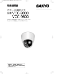
L5BU2_XE(INSTALLATION).book 0 ページ
2007年5月10日 木曜日 午後2時23分
INSTALLATION MANUAL
Color CCD Camera
Install these units securely according to this installation
manual. Be aware that allowing them to fall may cause
personal injury.
This installation should be made by a qualified service
person and should conform to all local codes.
Important
• Be careful when opening holes for installing the unit.
Work with the power and video cables pulled out for
easy installation.
• Make sure to properly perform waterproofing for the
ceiling where you are installing the unit.
• Make sure that the surface in the installation location
has no unevenness and is strong enough to bear the
total weight of the unit.
• Install this unit in an environment where the
temperature range stays between -10°C/+14°F and
+50°C/+122°F (no condensation allowed).
CAUTION: For VA-80S (Power Borard Unit)
ALL-POLE MAINS SWITCH with a contact separation of
at least 3mm in each pole shall be incorporated in the
electrical installation of the building.
Before Installing the Unit
Remove the plastic cover (A) and then the
tape (B) fixing the lens.
Put back the plastic cover (A), and turn it
clockwise until you hear it click to securely
lock it.
(A)
(B)
中文简体
Deutsch
Pattern Sheet (inserted at the end of this manual)
Français
Product Lineup . . . . . . . . . . . . . . . . . . . . . . . . . . . . . . . 1
Surface Mount . . . . . . . . . . . . . . . . . . . . . . . . . . . . . . . . 2
In-ceiling Mount (Closed Type) . . . . . . . . . . . . . . . . . . 3
In-ceiling Mount (Open Type) . . . . . . . . . . . . . . . . . . . . 4
Connections and Settings . . . . . . . . . . . . . . . . . . . . . . 5
Address Settings Table . . . . . . . . . . . . . . . . . . . . . . . . . 7
Español
Contents
English
Please read this manual before installing and using this unit, and always follow the instructions in it for proper
use. Please also read the separate Instruction Manual before using the unit for proper use.
L5BU2_XE(INSTALLATION).book 1 ページ
2007年5月10日 木曜日 午後2時23分
Product Lineup
To install the camera unit, the optional housing is required. When using a housing, be sure to choose the correct
one for your environment of use.
Indoor Type
(Surface Mount)
(In-ceiling Mount)
+
☞P3
☞P4
Outdoor Type
☞P2
☞ Refer to the instruction
manual supplied with
each product.
☞ Refer to the instruction manual supplied
with each product.
Pole Mounting
Adapter (VA-80AP)
In-ceiling
Bracket
In-ceiling
Bracket
Closed Type
Open Type
VA-80ME
VA-80MF
Pendant Mounting
Bracket (VA-80BP)
Wall Mounting
Bracket (VA-80BW)
Attachment (VA-80A)
Power Board
Unit
(VA-84S;
for AC24V)
(VA-80S;
for AC230V)
Power Board
Unit
(VA-84S;
for AC24V)
(VA-80S;
for AC230V)
Power Board Unit
(VA-84S; for AC24V)
(VA-80S; for AC230V)
Surface Cover
VA-80F
–1–
Corner Mounting
Adapter (VA-80AC)
Outdoor Housing (VA-80EX)
Power Board Unit
(VA-84S; for AC24V)
(VA-80S; for AC230V)
● Clear Dome Cover (VA-CM8C)
● Smoked Dome Cover (VA-CM8S)
L5BU2_XE(INSTALLATION).book 2 ページ
2007年5月10日 木曜日 午後2時23分
Surface Mount
VA-80F
Make sure to also consult the Surface Cover Instruction Manual.
2
1. Installing the power board unit
1 Place the pattern sheet at the end of this manual on
1
A
the ceiling, mark the locations and drill the holes for
the cables and screws.
● Pull out the cables from the ceiling.
B
B
2 Attach the supplied dust sheet (A) to the base of the
power board unit and the detachable piece of the
sheet (B) to the side.
● Peel off the release-coated paper from the dust sheet
before attaching.
3 Pass the cables through the slit (C) in the dust
sheet.
4 Fix the power board unit to the ceiling using the
supplied screws (D) (4 places).
3
Surface routing (ceiling)
Pass the cables
through the cable hole
(E) at the side of the
power board unit, and
attach the dust sheet
(A) as shown in the
figure.
C
5
D
5 Connect the cables and set the switches.
☞ See “Connections and Settings” on page 5.
E
4D
A
G6
2. Mounting the camera unit
6 Fasten the camera unit safety wire (F) to the hook
(G) on the inner side of the power board unit.
7 Align the arrows (H) of the same color (blue) on the
camera unit and the power board unit, and push the
camera unit until they click.
F
8 Align the arrows (H) of the same color (blue) on the
H; Blue 7
inner side of the surface cover and the power board
unit, and fix the cover by rotating it clockwise.
■ How to attach the drop-prevention cable
(accessory)
1) Peel off the two-sided tape (K) at the end of the cable
and attach it to the hook (L) on the inner side of the
surface cover as shown in the figure.
2) Fasten the cable to the hook (M) on the side of the
power board unit.
H; Blue 8
M
K
Protrusion
Removed in case of
surface routing.
L
■ To remove the camera unit
Accessories
Dust sheet
–2–
Drop-prevention
cable
Screw (for power
board unit)
L5BU2_XE(INSTALLATION).book 3 ページ
2007年5月10日 木曜日 午後2時23分
In-ceiling Mount (Closed Type)
VA-80ME
Make sure to also consult the In-ceiling Bracket Closed Type Instruction Manual.
1
1. Installing the power board unit
φ192 mm/7.6”
1 Draw a circumference on the ceiling using the
B
A
supplied drop-prevention cable (A) as compass, and
drill a hole for installing the in-ceiling bracket.
● Pull out the cables from the ceiling.
B
2 Pass the supplied screws a and washer b through
each of the power board unit screw holes (B) and
fasten them loosely using washers (4 places).
2
B
a
B
3 C; Blue
b
3 Align the arrows (C) of the same color (blue) on the
power board unit and the in-ceiling bracket, and
mount the power board unit. Tighten firmly the
screws (B) loosely fastened in the previous step.
● Pass the video cable (D) through the bracket cable
hole as preparation for the next step.
D
5
2. Installing on the ceiling
4 Attach the supplied safety wire (E) to the ceiling
beam, for example, then connect it to the
bracket-top hook (F).
E
5 Connect the video cable and pass the connection
F
4
cables through the bracket.
E
4
F
6 Insert the bracket into the ceiling hole and fix it
using screws (G) (2 places).
7 Connect the cables and set the switches.
6
☞ See “Connections and Settings” on page 5.
G
G
8 Align the arrows (C) of the same color (blue) on the
G
6
camera unit and the inner side of the bracket, and
push the camera unit until they click.
7
9 Align the SANYO logos on the supplied bracket
cover and the bracket, and push the cover until they
click.
G
■ How to attach the drop-prevention cable
(accessory)
Fasten the drop-prevention cable (A) to the hooks (H) on
the bracket and its cover, then slide the cable as shown in
the figure.
C; Blue 8
H
A
9
H
■ To remove the camera unit
Accessories
Screw a, washer b
(for power board unit)
Drop-prevention
cable
–3–
Safety wire
Bracket cover
L5BU2_XE(INSTALLATION).book 4 ページ
2007年5月10日 木曜日 午後2時23分
In-ceiling Mount (Open Type)
VA-80MF
Make sure to also consult the In-ceiling Bracket Open Type Instruction Manual.
1
1. Installing the power board unit
2
φ196 mm/7.7”
a
1 Drill a hole (φ196 mm/7.7”) in the ceiling for
b
installing the in-ceiling bracket.
● Pull out the cables from the ceiling.
A
A
2 Pass the supplied screws a and washer b through
each of the power board unit screw holes (A) and
fasten them loosely using washers (4 places).
A
3 Align the blue sticker (B) on the bracket and the
3 B; Blue
arrow (B) of the same color on the power board unit,
and then mount the power board unit in the bracket.
● When inserting the power board unit, do it diagonally.
A
4 Mount the power board unit in the in-ceiling bracket.
7
Tighten firmly the screws (A) loosely fastened in the
previous step.
C
2. Installing on the ceiling
5 Attach the supplied safety wire (C) to the ceiling
5
beam, for example, then connect it to the
bracket-top hole (D).
D
6 Pass the connection cables through the slit in the
6
dust sheet (E), and connect the video cable.
E
7 Insert the bracket into the ceiling hole and fix it
5
using screws (F) (2 places).
C
D
8 Connect the cables and set the switches.
7
☞ See “Connections and Settings” on page 5.
9 Align the blue sticker (B) on the bracket and the
arrow (B) of the same color on the camera unit, and
then push the camera unit until they click.
8
À Align the SANYO logos on the supplied bracket
F
F
7
F
cover and the bracket, and push the cover until they
click.
■ How to attach the drop-prevention cable
(accessory)
B; Blue 9
Fasten the drop-prevention cable (G) to the hooks (H) on
the bracket and its cover, then slide the cable as shown in
the figure.
H
G
H
■ To remove the camera unit
Accessories
Dust sheet
–4–
Screw a, washer b
(for power board unit)
Drop-prevention cable
Safety wire
Bracket cover
L5BU2_XE(INSTALLATION).book 5 ページ
2007年5月10日 木曜日 午後2時23分
Connections and Settings
Do not connect the power cord until all other
connections have been completed.
Make sure to also consult the Power Board Unit Instruction Manual.
Power Supply Connection
G
N
Monitor Connection
For the connections use cables higher than
18 AWG.
☞ When using AC 24 V, follow the connection steps in
the leaflet titled “Connecting the power cable” that
comes with the power board unit (VA-84S).
L
<Live>
<Neutral>
<Ground>
Supported coaxial cables
Cable type
RG-59U (3C-2V)
RG-6U (5C-2V)
RG-11U (7C-2V)
Length
250 m (273.4 yd) max.
500 m (546.8 yd) max.
600 m (656.2 yd) max.
AC 230 V
• Using different cables from those specified here may attenuate the
video and/or sync signals and interfere with correct transmission.
• RG-59U coaxial cables can be used when distance between
devices is short, but not in duct or aerial routing.
A
• Fix the power cable end firmly so that the power
terminal connection does not come loose. Use
solderless terminals (ring or spade type) for wiring.
• After connection, always install the supplied power
terminal cover A for safety reasons.
BNC type
Joint board
2
1
Connections
SIDE-A
Switch Settings
1 System control setting switches
1 Controller connection
B
L
O
R
B
K
R
D
ON
• Switch 6 is unused.
• The factory setting is represented in bold.
WH S
B
R
LL
Y
G
R
LL
White
SIDE-B
1
3
4
5
6
1 234
1 Baud rate
Yellow
2
Set the same baud rate as that on the camera.
Switch
2400
4800
9600
19200
485A
485B
2 Alarm signal input
✱
IN 1 - 8
To COM
Set either to RS485 or coaxial (COAX).
Switch
Coaxial (COAX)
RS485
3 Alarm signal output
If a lamp is connected to this cable, it will light up
when an alarm signal is received or when the
built-in motion sensor detects movement.
Set the protocol for controlling the camera.
Switch
SSP (SANYO)
PELCO
Alarm output
signal
SET
SET
SET
SET
SET
SET
SET
SET
SET
PRESET
MENU
OFF
BACK
“OFF” is set by default.
When connecting multiple cameras, termination setting must be “ON”
on the last camera while it must be “OFF” on all others.
2 Address setting switches
ALARM
y
ALARM IN
ALARM OUT
ALARM DISABLE
1
1
OFF
MOTION
ALARM DISPLAY
OFF
OFF
PRESET
MENU
OFF
BACK
4
OFF
ON
4 Termination (Switch 5)
✱ All connection cables should be 24 AWG or higher with a
maximum length of no more than 600 m (656.2 yd).
☞ For details on 2 and 3, refer to the “Alarm Settings (ALARM)” in
the Instruction Manual.
CAMERA
LENS
PAN/TILT
AUTO MODE
ALARM
PRIVACY MASK
PASSWORD
LANGUAGE
OPTION
3
ON
OFF
3 Protocol
✱
To COM
2
OFF
OFF
ON
ON
2 Control method
Alarm input
signal
OUT 1/2
1
OFF
ON
OFF
ON
y
Set the camera address.
See “Address Settings Table” on page 7.
–5–
ON
1
2
3
4
5
6
7
8
L5BU2_XE(INSTALLATION).book 6 ページ
2007年5月10日 木曜日 午後2時23分
Connections and Settings
■ To prevent electromagnetic interference
Be sure to attach the clamping cores supplied with the camera unit to the cables as illustrated.
Power cable
Control and alarm input/output cables
Video cable
■ Connections for using coaxial control (System connection)
(1 - 16)
Video input
terminal
Video input
terminal
Camera
Camera
Digital video recorder (sold separately)
1
2
3
4
5
6
7
8
9
10
11
12
13
14
15
16
IN
OUT
MONITOR OUT
MON2
MAIN
A RS-485 B
DO NOT CONNECT TO PHONE LINE
Video input
terminal
Terminator
switch
Communication conversion
connectors
Monitor
(sold separately)
A TELEMETRY B
System controller
(sold separately)
–6–
VIDEO
L5BU2_XE(INSTALLATION).book 7 ページ
2007年5月10日 木曜日 午後2時23分
Address Settings Table
Addresses are specified by setting the switches to ON/OFF.
In the table, the circle mark “m” means ON. Set switches as shown in the table.
ON
PELCO protocol: 1 - 255
ON
SANYO protocol: 1 - 127
ON
3
4
5
6
7
8
1
2
3
4
5
6
7
8
OFF
2
OFF
1
Switch 8
• Address 1 - 127: OFF
• Address 128 - 255: ON
ON
• Switch 8 is unused.
Address
(Camera No.)
Protocol
SANYO/PELCO PELCO
0*
128
1
129
2
130
3
131
4
132
5
133
6
134
7
135
8
136
9
137
10
138
11
139
12
140
13
141
14
142
15
143
16
144
17
145
18
146
19
147
20
148
21
149
22
150
23
151
24
152
25
153
26
154
27
155
28
156
29
157
30
158
31
159
32
160
33
161
34
162
35
163
36
164
37
165
38
166
39
167
40
168
41
169
42
170
Switch No.
1 2 3 4 5 6 7
m
m
mm
m
m
mm
mmm
m
m
m
m m
mm m
mm
m mm
mmm
mmmm
m
m
m
m
m
mm
m
m m
m m m
mm m
mmm m
mm
m
mm
m mm
mm mm
mmm
m mmm
mmmm
mmmmm
m
m
m
mm
m
m
mm
mmm
m
m
m
m
m
m
m
m
m
m
m
m
m
m
m
m
m
Address
(Camera No.)
Protocol
SANYO/PELCO PELCO
43
171
44
172
45
173
46
174
47
175
48
176
49
177
50
178
51
179
52
180
53
181
54
182
55
183
56
184
57
185
58
186
59
187
60
188
61
189
62
190
63
191
64
192
65
193
66
194
67
195
68
196
69
197
70
198
71
199
72
200
73
201
74
202
75
203
76
204
77
205
78
206
79
207
80
208
81
209
82
210
83
211
84
212
85
213
Switch No.
1 2 3 4 5 6 7
mm
m
mm
m mm
mmm
mmmm
m
m
m
m
m
mm
m
mm
m
mm
mm
mm
m mm
m m mm
mm mm
mmm mm
mmm
m
mmm
m mmm
mm mmm
mmmm
m mmmm
mmmmm
mmmmmm
m
m
mm
m
m
mm
mmm
m
m
m
m m
mm m
mm
m mm
mmm
mmmm
m
m
m
mm
m
m
m
m
m
m
m
m
m
m
m
m
m
m
m
m
m
m
m
m
m
m
m
m
m
m
m
m
m
m
m
Address
(Camera No.)
Protocol
SANYO/PELCO PELCO
86
214
87
215
88
216
89
217
90
218
91
219
92
220
93
221
94
222
95
223
96
224
97
225
98
226
99
227
100
228
101
229
102
230
103
231
104
232
105
233
106
234
107
235
108
236
109
237
110
238
111
239
112
240
113
241
114
242
115
243
116
244
117
245
118
246
119
247
120
248
121
249
122
250
123
251
124
252
125
253
126
254
127
255
* When setting the address by using the menu screen on the camera, set the address setting switches to “0”.
–7–
Switch No.
1 2 3 4 5 6 7
mm
mmm
m
m
mm
m
mm
m mm
mm mm
mmm
m mmm
mmmm
mmmmm
m
m
m
m
m
m
m
m
m
m
mm
m
mm
m
mm
mm
mm
m
mm
m m
mm
mm
mm
mmm
mm
m mm
m
m mm
m m mm
mm m mm
mm mm
m mm mm
mmm mm
mmmm mm
mmm
m
mmm
m
mmm
mm
mmm
m mmm
m m mmm
mm mmm
mmm mmm
mmmm
m
mmmm
m mmmm
mm mmmm
mmmmm
m mmmmm
mmmmmm
mmmmmmm
L5BU2_XE(INSTALLATION).book 0 ページ
2007年5月10日 木曜日 午後2時23分
MANUEL D’INSTALLATION
Caméra CCD couleur
Installez ces unités de façon sûre en respectant les
instructions du présent manuel d’installation. Attention,
leur chute pourrait entraîner des blessures corporelles.
Cette installation doit être effectuée par une personne qualifiée du
service technique et doit être conforme à tous les codes locaux.
Avant d’installer et d’utiliser cet appareil, veuillez lire avec attention le présent manuel et respectez toujours
les instructions d’utilisation fournies. Lisez aussi le Manuel d’instructions avant d'utiliser le groupe correctement.
Important
• Attention lorsque vous percez des trous pour installer
le groupe. Afin de faciliter l’installation, procédez avec
les câbles d’alimentation et vidéo tirés à l’extérieur.
• Lors de l’installation du groupe, veillez à bien
imperméabiliser le plafond d’installation.
• Assurez-vous que la surface du lieu d’installation ne
présente aucune irrégularité et est assez solide pour
supporter le poids total du groupe caméra.
• Installez ce groupe dans un environnement où la
plage de températures reste entre -10°C/+14°F et
+50°C/+122°F (aucune condensation autorisée).
ATTENTION: Pour VA-80S (Unité de carte d’alimentation)
L’ INTERRUPTEUR SECTEUR OMNIPLAIRE dote d’un
separateur de contact de 3mm minimum a chaque pole
doit etre insere dans le circuit electrique de l'immeuble.
Avant d'installer le groupe
Déposez la protection de plastique (A) puis
retirez le ruban adhésif (B) maintenant
l’objectif en place.
Reposez la protection de plastique (A) puis
tournez-la dans le sens horaire jusqu’à
entendre un déclic pour la verrouiller
fermement.
(A)
(B)
Français
中文简体
Deutsch
Modèle
(Pattern Sheet: inclus à la fin de cette brochure)
Español
Gamme de produits. . . . . . . . . . . . . . . . . . . . . . . . . . . . 1
Montage en surface . . . . . . . . . . . . . . . . . . . . . . . . . . . 2
Montage encastré au plafond (type fermé) . . . . . . . . . 3
Montage encastré au plafond (type ouvert) . . . . . . . . 4
Branchements et réglages . . . . . . . . . . . . . . . . . . . . . . 5
Tableau des réglages d’adresse . . . . . . . . . . . . . . . . . 7
English
Table des matières
L5BU2_XE(INSTALLATION).book 1 ページ
2007年5月10日 木曜日 午後2時23分
Gamme de produits
Pour installer le groupe caméra, le boîtier en option est nécessaire. Quand vous utilisez un boîtier, veillez à choisir
le boîtier adapté à l’environnement d’utilisation.
Modèle pour intérieur
(Montage encastré au plafond)
☞Page 3
☞Page 4
Modèle pour extérieur
(Montage en surface)
☞Page 2
☞ Reportez-vous au
manuel d’instructions
fourni avec chaque
produit.
☞ Reportez-vous au manuel d’instructions
fourni avec chaque produit.
Adaptateur de
montage sur
poteau (VA-80AP)
Support
Support
d’encastrement d’encastrement
au plafond
au plafond
de type fermé de type ouvert
VA-80ME
Support suspendu
(VA-80BP)
VA-80MF
Attache (VA-80A)
Unité de carte
d’alimentation
(VA-84S ;
pour CA 24 V)
(VA-80S ;
pour CA 230 V)
Support mural
(VA-80BW)
Adaptateur de
montage en angle
(VA-80AC)
Unité de carte
d’alimentation
(VA-84S ;
pour CA 24 V)
(VA-80S ;
pour CA 230 V)
Unité de carte d’alimentation
(VA-84S ; pour CA 24 V)
(VA-80S ; pour CA 230 V)
Boîtier de surface
VA-80F
–1–
Boîtier pour extérieur (VA-80EX)
Unité de carte d’alimentation
(VA-84S ; pour CA 24 V)
(VA-80S ; pour CA 230 V)
● Couvercle en dôme transparent (VA-CM8C)
● Couvercle en dôme fumé (VA-CM8S)
L5BU2_XE(INSTALLATION).book 2 ページ
2007年5月10日 木曜日 午後2時23分
Montage en surface
VA-80F
Consultez également le manuel d’instructions du boîtier de surface.
2
1. Installation de l’unité de carte
d’alimentation
1
A
1 Placez le modèle figurant en fin du présent manuel
B
au plafond, marquez les emplacements et percez
les trous pour les câbles et les vis.
● Tirez les câbles à l’extérieur du plafond.
2 Fixez la feuille de protection fournie (A) à la base
de l’unité de carte d’alimentation et le morceau
détachable de la feuille (B) sur le côté.
● Séparez le papier couché antiadhésif de la feuille
de protection avant de la fixer.
3 Passez les câbles dans la fente (C) de la feuille
de protection.
B
3
Passage en surface
(au plafond)
C
Passez les câbles à
travers le trou pour câble
(E) sur le côté de l’unité
de carte d’alimentation et
fixez la feuille de protection
(A) comme indiqué dans
la figure.
4 Fixez l’unité de carte d’alimentation au plafond
5
D
à l’aide des vis fournies (D) (4 emplacements).
5 Branchez les câbles et réglez les interrupteurs.
E
☞ Voir « Branchements et réglages » page 5.
4D
A
G6
2.Pose du groupe caméra
6 Fixez le fil de sécurité (F) du groupe caméra au
crochet (G) sur l’intérieur de l’unité de carte
d’alimentation.
7 Alignez les flèches (H) de même couleur (bleu) sur
F
le groupe caméra et l’unité de carte d’alimentation
et poussez le groupe caméra jusqu’à ce qu’ils
s’enclenchent.
H ; bleu 7
8 Alignez les flèches (H) de même couleur (bleu) sur
l’intérieur du boîtier de surface et l’unité de carte
d’alimentation et fixez le boîtier en le tournant dans
le sens horaire.
■ Fixation du câble anti-chute (accessoire)
1) Dénudez le ruban double face (K) à l’extrémité du
câble et fixez-le au crochet (L) sur l’intérieur du
boîtier de surface comme indiqué dans la figure.
H ; bleu 8
2) Fixez le câble au crochet (M) du côté de l’unité
de carte d’alimentation.
M
Pour déposer le groupe
caméra
K
Déposé en cas de
passage des câbles
en surface.
Saillie
L
■ Pour déposer le groupe caméra
Accessoires
Feuille de
protection
–2–
Câble anti-chute
Vis (pour unité de
carte d’alimentation)
L5BU2_XE(INSTALLATION).book 3 ページ
2007年5月10日 木曜日 午後2時23分
Montage encastré au plafond (type fermé)
VA-80ME
Consultez également le manuel d’instructions du support d’encastrement au plafond de type fermé.
1
1. Installation de l’unité de carte
d’alimentation
φ192 mm/7,6”
B
A
1 Tracez un cercle au plafond en utilisant le câble
anti-chute fourni (A) comme compas et percez un trou
pour poser le support d'encastrement au plafond.
● Tirez les câbles à l’extérieur du plafond.
2 Passez les vis a/rondelle b fournies à travers
chaque trou (B) de vis de l’unité de carte
d’alimentation et fixez-les sans serrer à l’aide des
rondelles (4 emplacements).
B
2
B
a
B
3 C ; bleu
b
3 Alignez les flèches (C) de même couleur (bleu) sur
l’unité de carte d’alimentation et le support
d'encastrement au plafond et montez l’unité de carte
d’alimentation. Serrez fermement les vis (B) qui
avaient été fixées sans les serrer à l’étape
précédente.
● Passez le câble vidéo (D) dans le trou de câble
du support pour préparer la phase suivante.
D
5
2. Installation au plafond
4 Fixez le fil de sécurité fourni (E) à la poutre du
E
plafond par exemple, puis connectez-le au crochet
supérieur du support (F).
E
F
4
4
F
5 Branchez le câble vidéo et passez les câbles
de branchement dans le support.
6 Introduisez le support dans le trou au plafond et
6
fixez-le au moyen des vis (G) (2 emplacements).
G
G
7 Branchez les câbles et réglez les interrupteurs.
G
6
☞ Voir « Branchements et réglages » page 5.
7
8 Alignez les flèches (C) de même couleur (bleu) sur le
groupe caméra et l’intérieur du support et poussez
le groupe caméra jusqu’à ce qu’ils s’enclenchent.
G
9 Alignez les logos SANYO sur la protection de
support fournie et sur le support et poussez la
protection jusqu’à ce que les deux s’enclenchent.
■ Fixation du câble anti-chute (accessoire)
Fixez le câble anti-chute (A) aux crochets (H) sur le support
et sa protection puis faites glisser le câble comme indiqué
dans la figure.
C ; bleu 8
H
9
A
H
■ Pour déposer le groupe caméra
Accessoires
Vis a, rondelle b
(pour unité de carte
d’alimentation)
Câble anti-chute
–3–
Fil de sécurité
Protection de support
L5BU2_XE(INSTALLATION).book 4 ページ
2007年5月10日 木曜日 午後2時23分
Montage encastré au plafond (type ouvert)
VA-80MF
Consultez également le manuel d’instructions du support d'encastrement au plafond de type ouvert.
1
1. Installation de l’unité de carte
d’alimentation
2
φ196 mm/7,7”
a
b
1 Percez un trou (φf196 mm/7.7”) dans le plafond pour
A
installer le support d’encastrement au plafond.
● Tirez les câbles à l’extérieur du plafond.
2 Passez les vis a/rondelle b fournies à travers
chaque trou (A) de vis de l’unité de carte
d’alimentation et fixez-les sans serrer à l’aide des
rondelles (4 emplacements).
A
A
3 B ; bleu
3 Alignez l’autocollant bleu (B) du support et la flèche
A
(B) de même couleur sur l’unité de carte
d’alimentation puis montez l’unité de carte
d’alimentation dans le support.
● Insérez l’unité de carte d’alimentation en diagonale.
4 Montez l’unité de carte d’alimentation dans le
support d'encastrement au plafond. Serrez
fermement les vis (A) qui avaient été fixées sans les
serrer à l’étape précédente.
7
C
5
2. Installation au plafond
D
6
5 Fixez le fil de sécurité fourni (C) à la poutre du
E
plafond par exemple, puis attachez-le à l’orifice
supérieur du support (D).
5
6 Passez les câbles de branchement dans la fente de
C
D
7
la feuille de protection (E) et branchez le câble
vidéo.
7 Introduisez le support dans le trou au plafond et
fixez-le au moyen des vis (F) (2 emplacements).
8
8 Branchez les câbles et réglez les interrupteurs.
F
7
F
☞ Voir « Branchements et réglages » page 5.
F
9 Alignez l’autocollant bleu (B) du support et la flèche
(B) de même couleur du groupe caméra puis
poussez le groupe caméra jusqu’à ce qu’ils
s’enclenchent.
À Alignez les logos SANYO sur la protection
de support fournie et sur le support et poussez la
protection jusqu’à ce que les deux s’enclenchent.
B ; bleu 9
■ Fixation du câble anti-chute (accessoire)
Fixez le câble anti-chute (G) aux crochets (H) sur le support
et sa protection puis faites glisser le câble comme indiqué
dans la figure.
H
G
H
Accessoires
■ Pour déposer le groupe caméra
DusFeuille de
protection
–4–
Vis a, rondelle b
(pour unité de carte
d’alimentation)
Câble anti-chute
Fil de sécurité
Protection de support
L5BU2_XE(INSTALLATION).book 5 ページ
2007年5月10日 木曜日 午後2時23分
Branchements et réglages
Ne branchez pas le cordon d’alimentation tant que
les autres branchements n’ont pas été effectués.
Consultez également le manuel d’instructions de l’unité de carte d’alimentation.
Branchement de l'alimentation
G
N
Branchement du moniteur
Câbles coaxiaux acceptés
Pour les connexions, utilisez des câbles d’une
épaisseur supérieure à 18 AWG.
L
Type de câble
Longueur
RG-59U (3C-2V) 250 m (273,4 yd) maxi
RG-6U (5C-2V) 500 m (546,8 yd) maxi
RG-11U (7C-2V) 600 m (656,2 yd) maxi
☞ En cas d’utilisation de CA 24 V, suivez les étapes de
branchement du feuillet intitulé « Branchement du câble
d’alimentation » fourni avec l’unité de carte
d’alimentation (VA-84S).
<Sous tension>
<Neutre>
<Terre>
CA 230 V
• L’utilisation de câbles autres que ceux spécifiés peut atténuer les
signaux vidéo et/ou sync et réduire la qualité de la transmission.
• Des câbles coaxiaux RG-59U peuvent être utilisés lorsque
la distance entre les appareils est courte, mais pas si les câbles
passent dans des conduits ou s’ils sont en suspension.
A
• Fixez solidement l’extrémité du câble d’alimentation
de façon à ce que la connexion d’alimentation ne se
détache pas. Utilisez des bornes sans soudure (de
type à anneau ou ouvertes) pour le câblage.
• Après la connexion, posez toujours le couvre-bornes
d’alimentation fourni A pour des raisons de sécurité.
Type BNC
Plaque de
connexion
SIDE-A
SIDE-B
2
1
Branchements
COTE-A
COTE-B
Réglage des interrupteurs
B
L
O
R
B
K
R
D
1 Commutateurs de réglage
1 Connexion contrôleur
ON
des commandes du système
WH S
B
R
LL
Y
G
R
LL
Blanc
1
• L’interrupteur 6 n’est pas utilisé.
• La valeur du réglage d’usine apparaît en gras.
Jaune
2
3
4
5
6
1 234
1 Débit en bauds
Réglez le mêe débit en bauds que sur la caméra.
485A
485B
Interrupteur
2400
4800
9600
19200
2 Entrée du signal d’alarme
✱
Signal d’entrée
d’alarme
IN 1 - 8
Vers COM
Réglez sur RS485 ou sur coaxial (COAX).
Interrupteur
Coaxial (COAX)
RS485
Si un voyant est raccordé à ce câble, il s’allume
lorsque le signal d’alarme est reçu ou lorsque
le capteur de mouvement intégré détecte un
mouvement.
✱
Réglez le protocole de commande de la caméra.
Interrupteur
SSP (SANYO)
PELCO
✱ Tous les câbles de branchement doivent être au moins 24
AWG et d’une longueur maximale de 600 m (656,2 yd).
« ARRÊT » est réglé par défaut.
Quand vous branchez plusieurs caméras, le réglage de terminaison
doit être sur « ON » (MARCHE) sur la dernière caméra et sur
« ARRÊT » sur toutes les autres.
ALARME
REG
REG
REG
REG
REG
REG
REG
REG
REG
PREREGLAGE
MENU
ARR
RETOUR
y
ENT ALARME
SORTIE ALARME
DESACT ALARME
1
1
ARR
y
2 Commutateurs de réglage
ARR
MOUVEMENT
AFFICHER ALARME ARR
PREREGLAGE
MENU
4
ARRÊT
MARCHE
4 Terminaison (interrupteur 5)
☞ Pour plus de détails sur 2 et 3, consultez le paragraphe
« Réglage d’alarme (ALARME) » du manuel d’instructions.
CAMERA
LENTILLE
PAN/INCL.
MODE AUTO
ALARME
MASQUE
M/PASSE
LANGUE
OPTION
3
MARCHE
ARRÊT
3 Protocole
Signal de sortie
d’alarme
Vers COM
2
ARRÊT
ARRÊT
MARCHE
MARCHE
2 Méthode de commande
3 Sortie du signal d’alarme
OUT 1/2
1
ARRÊT
MARCHE
ARRÊT
MARCHE
d’adresse
ARR
RETOUR
Réglez l’adresse de caméra.
Voir « Tableau des réglages d’adresse » page 7.
–5–
ON
1
2
3
4
5
6
7
8
L5BU2_XE(INSTALLATION).book 6 ページ
2007年5月10日 木曜日 午後2時23分
Branchements et réglages
■ Pour empêcher les interférences électromagnétiques
Veillez à fixer les noyaux en ferrite fournis avec le groupe caméra aux câbles comme indiqué dans la figure.
Câble d’alimentation
Câbles de commande et d'entrée/sortie
d'alarme
Câble vidéo
■ Connexions pour l’utilisation de la commande coaxiale (Connexion système)
(1 - 16)
Borne d’entrée
Borne d’entrée
vidéo
vidéo
Caméra
Caméra
Enregistreur numérique (vendu séparément)
1
2
3
4
5
6
7
8
9
10
11
12
13
14
15
16
IN
OUT
MONITOR OUT
MON2
MAIN
A RS-485 B
DO NOT CONNECT TO PHONE LINE
Borne d’entrée
vidéo
Interrupteur de
terminaison
Connecteurs de conversion
de communication
Moniteur
(vendu séparément)
A TELEMETRY B
Contrôleur de système
(vendu séparément)
–6–
VIDEO
L5BU2_XE(INSTALLATION).book 7 ページ
2007年5月10日 木曜日 午後2時23分
Tableau des réglages d’adresse
Les adresses sont spécifiées en réglant les interrupteurs sur MARCHE/ARRÊT
Dans le tableau, le cercle « m » signifie MARCHE. Réglez les interrupteurs comme indiqué dans le tableau.
ON
Protocole PELCO: 1 - 255
ON
Protocole SANYO: 1 - 127
ON
3
4
5
6
7
8
1
2
3
4
5
6
7
8
OFF
2
OFF
1
Interrupteur 8
• Adresse 1 - 127 : ARRÊT
• Adresse 128 - 255 : MARCHE
ON
• L’interrupteur 8 n’est pas utilisé.
Adresse
(n° de caméra)
Protocole
SANYO/PELCO PELCO
0*
128
1
129
2
130
3
131
4
132
5
133
6
134
7
135
8
136
9
137
10
138
11
139
12
140
13
141
14
142
15
143
16
144
17
145
18
146
19
147
20
148
21
149
22
150
23
151
24
152
25
153
26
154
27
155
28
156
29
157
30
158
31
159
32
160
33
161
34
162
35
163
36
164
37
165
38
166
39
167
40
168
41
169
42
170
N° interrupteur
1 2 3 4 5 6 7
m
m
mm
m
m
mm
mmm
m
m
m
m m
mm m
mm
m mm
mmm
mmmm
m
m
m
m
m
mm
m
m m
m m m
mm m
mmm m
mm
m
mm
m mm
mm mm
mmm
m mmm
mmmm
mmmmm
m
m
m
mm
m
m
mm
mmm
m
m
m
m
m
m
m
m
m
m
m
m
m
m
m
m
m
Adresse
(n° de caméra)
Protocole
SANYO/PELCO PELCO
43
171
44
172
45
173
46
174
47
175
48
176
49
177
50
178
51
179
52
180
53
181
54
182
55
183
56
184
57
185
58
186
59
187
60
188
61
189
62
190
63
191
64
192
65
193
66
194
67
195
68
196
69
197
70
198
71
199
72
200
73
201
74
202
75
203
76
204
77
205
78
206
79
207
80
208
81
209
82
210
83
211
84
212
85
213
N° interrupteur
1 2 3 4 5 6 7
mm
m
mm
m mm
mmm
mmmm
m
m
m
m
m
mm
m
mm
m
mm
mm
mm
m mm
m m mm
mm mm
mmm mm
mmm
m
mmm
m mmm
mm mmm
mmmm
m mmmm
mmmmm
mmmmmm
m
m
mm
m
m
mm
mmm
m
m
m
m m
mm m
mm
m mm
mmm
mmmm
m
m
m
mm
m
m
m
m
m
m
m
m
m
m
m
m
m
m
m
m
m
m
m
m
m
m
m
m
m
m
m
m
m
m
m
Adresse
(n° de caméra)
Protocole
SANYO/PELCO PELCO
86
214
87
215
88
216
89
217
90
218
91
219
92
220
93
221
94
222
95
223
96
224
97
225
98
226
99
227
100
228
101
229
102
230
103
231
104
232
105
233
106
234
107
235
108
236
109
237
110
238
111
239
112
240
113
241
114
242
115
243
116
244
117
245
118
246
119
247
120
248
121
249
122
250
123
251
124
252
125
253
126
254
127
255
N° interrupteur
1 2 3 4 5 6 7
mm
mmm
m
m
mm
m
mm
m mm
mm mm
mmm
m mmm
mmmm
mmmmm
m
m
m
m
m
m
m
m
m
m
mm
m
mm
m
mm
mm
mm
m
mm
m m
mm
mm
mm
mmm
mm
m mm
m
m mm
m m mm
mm m mm
mm mm
m mm mm
mmm mm
mmmm mm
mmm
m
mmm
m
mmm
mm
mmm
m mmm
m m mmm
mm mmm
mmm mmm
mmmm
m
mmmm
m mmmm
mm mmmm
mmmmm
m mmmmm
mmmmmm
mmmmmmm
* Lors du réglage de l’adresse à l’aide de l’écran de menus de la caméra, réglez les commutateurs de réglage d’adresse sur
« 0 ».
–7–
L5BU2_XE(INSTALLATION).book 0 ページ
2007年5月10日 木曜日 午後2時23分
MANUAL DE INSTALACIÓN
Cámara CCD a color
Instalar estas unidades de manera segura tal como se indica
en este manual de instalación. Tener en consideración que
si las mismas se caen pueden causar lesiones personales.
La instalación tiene que ser realizada por una persona de
servicio y tiene que estar de acuerdo con los códigos locales.
Antes de instalar y de usar esta unidad leer este manual y seguir las instrucciones del mismo para asegurar un
uso correcto. Leer además el manual de instrucciones que se suministra por separado antes de usar la unidad
para un uso correcto.
Importante
• Tener cuidado a la hora de abrir los orificios para instalar
la unidad. Trabajar sacando hacia afuera los cables de
vídeo y de energía para una instalación más fácil.
• Asegurarse de realizar una impermeabilización
apropiada del techo donde se instala la unidad.
• Comprobar que la superficie del lugar de instalación
no tiene desniveles y que es lo suficientemente
resistente como para soportar el peso total de
la unidad.
• Instalar esta unidad en un ambiente cuya temperatura
está entre -10°C/+14°F y +50°C/+122°F (no se
permite condensación).
PRECAUCIÓN: Para VA-80S (Placa de alimentación)
En la instalación eléctrica del edificio tiene que
incorporarse un INTERRUPTOR DE CORTE
OMNIPOLAR con una separación de contactos de por lo
menos 3mm en cada polo.
Antes de instalar la unidad
Quitar la cubierta de plástico (A) y a
continuación la cinta (B) que fija la lente.
Volver a colocar la cubierta de plástico (A) y
girarla hacia la derecha hasta que se oiga
un clic para bloquearla firmemente.
(A)
(B)
Français
中文简体
Deutsch
Plantilla
(Pattern Sheet: que se incluye en el final de este manual)
Español
Alineación del producto . . . . . . . . . . . . . . . . . . . . . . . . 1
Montaje en superficie . . . . . . . . . . . . . . . . . . . . . . . . . . 2
Montaje en el techo (Tipo cerrado) . . . . . . . . . . . . . . . 3
Montaje en el techo (Tipo abierto) . . . . . . . . . . . . . . . . 4
Conexiones y ajustes . . . . . . . . . . . . . . . . . . . . . . . . . . 5
Tabla de ajustes de dirección . . . . . . . . . . . . . . . . . . . 7
English
Contenido
L5BU2_XE(INSTALLATION).book 1 ページ
2007年5月10日 木曜日 午後2時23分
Alineación del producto
Para instalar la unidad de la cámara, es necesario el alojamiento opcional. Si se usa un alojamiento,
asegurarse de elegir uno apropiado para el entorno de uso.
Para interiores
(Montaje en el techo)
☞Página 3
☞Página 4
Para exteriores
(Montaje en superficie)
☞Página 2
☞ Consultar el manual de
instrucciones
suministrado con cada
producto.
☞ Consultar el manual de instrucciones
suministrado con cada producto.
Adaptador de
montaje de poste
(VA-80AP)
Soporte de
techo
tipo cerrado
Soporte de
techo
tipo abierto
VA-80ME
VA-80MF
Soporte de montaje
colgante (VA-80BP)
Soporte de montaje
de pared (VA-80BW)
Dispositivo de sujeción
(VA-80A)
Placa de
alimentación
(VA-84S;
para CA 24 V )
(VA-80S;
para CA 230 V)
Placa de
alimentación
(VA-84S;
para CA 24 V )
(VA-80S;
para CA 230 V)
Placa de alimentación
(VA-84S; para CA 24 V )
(VA-80S; para CA 230 V)
Cubierta de superficie
VA-80F
–1–
Adaptador de
montaje de ángulo
(VA-80AC)
Alojamiento para exteriores (VA-80EX)
Placa de alimentación
(VA-84S; para CA 24 V )
(VA-80S; para CA 230 V)
● Tapa de cúpula transparente (VA-CM8C)
● Tapa de cúpula ahumada (VA-CM8S)
L5BU2_XE(INSTALLATION).book 2 ページ
2007年5月10日 木曜日 午後2時23分
Montaje en superficie
VA-80F
Consultar además el manual de instrucciones de la cubierta de superficie.
2
1. Instalación de la placa de alimentación
1
A
1 Colocar la plantilla que se proporciona al final de este
manual en el techo, marcar las posiciones y perforar
los orificios para los cables y los tornillos.
B
● Sacar hacia afuera los cables del techo.
2 Pegar la hoja guardapolvo que se suministra (A)
a la base de la placa de alimentación y la pieza
separable de la hoja (B) al lado.
● Despegar el papel estucado despegable de la hoja
guardapolvo antes de pegarla.
3 Pasar los cables a través de la abertura (C) de la hoja
guardapolvo.
4 Fijar la placa de alimentación al techo mediante
los tornillos que se suministran (D) (4 posiciones).
5 Conectar los cables y ajustar los interruptores.
☞ Ver el apartado “Conexiones y ajustes” en la página 5.
B
Cableado de superficie
(techo)
Pasar los cables a
través del orificio para
cables (E) de la parte
lateral de la placa de
alimentación, y fijar la
hoja guardapolvo (A)
como se muestra en la
figura.
E
A
3
C
5
D
4D
G6
2. Montaje de la unidad de la cámara
6 Fijar el cable de seguridad de la unidad de la cámara
(F) al gancho (G) de la parte interna de la placa
de alimentación.
7 Alinear las flechas (H) del mismo color (azul)
de la unidad de la cámara y la placa de alimentación, y
empujar la unidad de la cámara hasta escuchar un clic.
8 Alinear las flechas (H) del mismo color (azul) de la
parte interna de la cubierta de superficie y la placa de
alimentación y fijar la cubierta haciéndola girar en el
sentido de las agujas del reloj.
F
H; Azul 7
■ Montaje del cable contra caídas (accesorio)
1) Despegar la cinta adhesiva de doble cara (K)
del extremo del cable y pegarla al gancho (L)
de la parte interna de la cubierta de superficie como se
indica en la figura.
2) Fijar el cable al gancho (M) de la parte lateral
de la placa de alimentación.
H; Azul 8
M
K
L
Se quita en caso
de cableado
de superficie.
Protuberancia
■ Para extraer la unidad de la cámara
Accesorios
Hoja guardapolvo
–2–
Cable contra
caídas
Tornillo
(para la placa de
alimentación)
L5BU2_XE(INSTALLATION).book 3 ページ
2007年5月10日 木曜日 午後2時23分
Montaje en el techo (Tipo cerrado)
VA-80ME
Consultar además el manual de instrucciones del soporte de techo tipo cerrado.
1
1. Instalación de la placa de alimentación
φ192 mm/7,6”
B
1 Dibujar una circunferencia en el techo usando como
A
compás el cable contra caídas que se suministra (A), y
perforar un orificio para la instalación del soporte de
techo.
B
● Sacar hacia afuera los cables del techo.
2 Pasar los tornillos a/arandela b que se suministran a
través de los orificios (B) para tornillos de la placa
de alimentación y fijarlos sin apretar usando arandelas
(4 posiciones).
3 Alinear las flechas (C) del mismo color (azul) de la
placa de alimentación y el soporte de techo y montar la
placa de alimentación. Apretar firmemente los tornillos
(B) que se habían dejado sin apretar en el paso
anterior.
● Pasar el cable del vídeo (D) a través del orificio para
el cable del soporte como preparación para el paso
siguiente.
2
B
a
B
3 C; Azul
b
D
5
2. Instalación en el techo
4 Fijar el cable de seguridad que se suministra (E)
E
a la viga del techo, por ejemplo, y conectarlo al gancho
superior del soporte (F).
5 Conectar el cable del vídeo y pasar los cables
de conexión a través del soporte.
6 Insertar el soporte en el orificio del techo y fijarlo
mediante los tornillos (G) (2 posiciones).
7 Conectar los cables y ajustar los interruptores.
E
F
4
4
F
6
☞ Ver el apartado “Conexiones y ajustes” en la página 5.
8 Alinear las flechas (C) del mismo color (azul) de la unidad
de la cámara y de la parte interna del soporte, y empujar
la unidad de la cámara hasta escuchar un clic.
9 Alinear el logotipo SANYO de la cubierta del soporte
que se suministra y el soporte y empujar la cubierta
hasta escuchar un clic.
G
G
G
6
7
G
■ Montaje del cable contra caídas (accesorio)
Fijar el cable contra caídas (A) a los ganchos (H)
del soporte y su cubierta y deslizar el cable como
se muestra en la figura.
C; Azul 8
H
A
H
9
■ Para extraer la unidad de la cámara
Accesorios
Tornillo a, arandela b
(para la placa de
alimentación)
Cable contra
caídas
–3–
Cable de seguridad
Cubierta del soporte
L5BU2_XE(INSTALLATION).book 4 ページ
2007年5月10日 木曜日 午後2時23分
Montaje en el techo (Tipo abierto)
VA-80MF
Consultar además el manual de instrucciones del soporte de techo tipo abierto.
1
1. Instalación de la placa de alimentación
2
φ196 mm/7,7”
a
1 Taladrar un orificio (φ196 mm/7.7”) en el techo para
b
instalar el soporte de techo.
● Sacar hacia afuera los cables del techo.
2 Pasar los tornillos a/arandela b que se suministran a
través de los orificios (A) para tornillos de la placa
de alimentación y fijarlos sin apretar usando arandelas
(4 posiciones).
3 Alinear la etiqueta azul (B) en el soporte y la flecha (B)
del mismo color en la unidad de la placa de
alimentación, a continuación montar la unidad de la
placa de alimentación en el soporte.
● Al insertar la placa de alimentación, hacerlo
diagonalmente.
4 Montar la placa de alimentación en el soporte de techo.
Apretar firmemente los tornillos (A) que se habían
dejado sin apretar en el paso anterior.
A
A
A
3 B; Azul
A
7
C
2. Instalación en el techo
5 Fijar el cable de seguridad que se suministra (C)
a la viga del techo, por ejemplo, y conectarlo al orificio
superior del soporte (D).
6 Pasar los cables de conexión a través de la abertura en
la hoja guardapolvo (E) y conectar el cable del vídeo.
7 Insertar el soporte en el orificio del techo y fijarlo
mediante los tornillos (F) (2 posiciones).
8 Conectar los cables y ajustar los interruptores.
☞ Ver el apartado “Conexiones y ajustes” en la página 5.
9 Alinear la etiqueta azul (B) del soporte y la flecha (B)
del mismo color de la unidad de la cámara, y empujar
la unidad de la cámara hasta escuchar un clic.
À Alinear el logotipo SANYO de la cubierta del soporte
que se suministra y el soporte y empujar la cubierta
hasta escuchar un clic.
5
D
6
E
5
D
7
8
F
F
7
F
■ Montaje del cable contra caídas (accesorio)
Fijar el cable contra caídas (G) a los ganchos (H) del
soporte y su cubierta y deslizar el cable como se muestra
en la figura.
B; Azul 9
H
G
C
H
■ Para extraer la unidad de la cámara
Accesorios
Hoja
guardapolvo
Tornillo a, arandela b
(para la placa de alimentación)
Cable de seguridad
–4–
Cable contra caídas
Cubierta del soporte
L5BU2_XE(INSTALLATION).book 5 ページ
2007年5月10日 木曜日 午後2時23分
Conexiones y ajustes
No conectar el cable de alimentación hasta que
no se haya terminado con todas las conexiones.
Consultar además el manual de instrucciones de la placa de alimentación.
Conexión de alimentación
G
N
Conexión del monitor
Cables coaxiales admitidos
Para las conexiones, usar cables de 18 AWG o más.
☞ Cuando se utilizan CA 24 V, seguir los pasos de
conexión del folleto "Conexión del cable de
alimentación" adjunto a la unidad de la placa de
alimentación (VA-84S).
L
<Con corriente>
<Neutro>
<A tierra>
Tipo de cable
Longitud
RG-59U (3C-2V) 250 m (273,4 yardas) máx.
RG-6U (5C-2V) 500 m (546,8 yardas) máx.
RG-11U (7C-2V) 600 m (656,2 yardas) máx.
CA 230 V
• El uso de cables que no son los que aquí se especifican podría
atenuar las señales de vídeo y/o de sincronización e interferir con
la transmisión correcta.
• Los cables coaxiales RG-59U pueden usarse si la distancia entre
los dispositivos es corta, no deben usarse con cableados aéreos o
en conductos.
A
• Fijar el extremo del cable de alimentación firmemente
de modo que la conexión del terminal de alimentación
no se afloje. Para el cableado usar terminales sin
soldaduras (tipo de anillo o de horquilla).
• Tras la conexión, por razones de seguridad, instalar siempre la
cubierta A del terminal de alimentación que se suministra.
Tipo BNC
Placa de
unión
SIDE-A
SIDE-B
2
1
LADO-A
Conexiones
LADO-B
Ajustes de los interruptores
B
L
O
R
B
K
R
D
1 Interruptores de ajuste de control
1 Conexión del controlador
ON
del sistema
WH S
B
R
LL
Y
G
R
LL
Blanco
1
• El interruptor 6 no se utiliza.
• El valor de ajuste de fábrica se representa
en negrita.
Amarillo
2
3
4
5
6
1 234
1 Tasa de baudios
Ajustar la misma tasa de baudios que la de la cámara.
485A
485B
Interruptor
2400
4800
9600
19200
2 Entrada de señal de alarma
✱
Señal de
entrada de
alarma
ENTRADA 1 - 8
A COM
Ajustar RS485 o coaxial (COAX).
Si hay una lámpara conectada a este cable, se
enciende cuando se recibe una señal de alarma o
cuando el sensor de movimiento incorporado
detecta movimiento.
✱
SALIDA 1/2
Interruptor
Coaxial (COAX)
RS485
Ajustar el protocolo para el control de la cámara.
Interruptor
SSP (SANYO)
PELCO
✱ Todos los cables de conexión deben ser 24 AWG o mayores
con un largo máximo de no más de 600 m (656,2 yardas).
☞ Para detalles acerca de 2 y 3, consultar el apartado “Ajustes
de alarma (ALARMA)” en el manual de instrucciones.
PREAJUSTES
MENU
OFF
ATRAS
y
ENTRADA ALARMA
SALIDA ALARMA
INHAB. ALARMA
1
1
OFF
MOVIMIENTO
VISUAL. ALARMA
OFF
OFF
PREAJUSTES
MENU
OFF
ATRAS
4
OFF
ON
4 Terminación (Interruptor 5)
Está ajustado en “OFF” por defecto.
Cuando se conectan varias cámaras, el ajuste de terminación tiene
que estar activado “ON” en la última cámara mientras tiene estar
desactivado “OFF” en las demás.
ALARMA
AJU
AJU
AJU
AJU
AJU
AJU
AJU
AJU
AJU
3
ON
OFF
3 Protocolo
Señal de salida
de alarma
CAMARA
LENTE
PAN/INCL.
MODO AUT.
ALARMA
MASCARA PRIV
CONTRASENA
IDIOMA
OPCION
2
OFF
OFF
ON
ON
2 Método de control
3 Salida de señal de alarma
A COM
1
OFF
ON
OFF
ON
y
2 Interruptores de ajuste
ON
de la dirección
Ajustar la dirección de la cámara.
Ver “Tabla de ajustes de dirección” en la página 7.
–5–
1
2
3
4
5
6
7
8
L5BU2_XE(INSTALLATION).book 6 ページ
2007年5月10日 木曜日 午後2時23分
Conexiones y ajustes
■ Para prevenir las interferencias electromagnéticas
Asegurarse de fijar los núcleos de bloqueo que se suministran con la unidad de la cámara a los cables como
se muestra.
Cable de alimentación
Cables de control y entrada/salida de
alarmas
Cable para vídeo
■ Conexiones para el uso del control coaxial (Conexión del sistema)
(1 - 16)
Terminal
de entrada
de vídeo
Terminal
de entrada
de vídeo
Cámara
Cámara
Grabador de vídeo digital (vendido por separado)
1
2
3
4
5
6
7
8
9
10
11
12
13
14
15
16
IN
OUT
MONITOR OUT
MON2
MAIN
A RS-485 B
DO NOT CONNECT TO PHONE LINE
Terminal
de entrada
de vídeo
Interruptor
de terminación
Conectores de conversión
de comunicación
Monitor
(vendido por separado)
A TELEMETRY B
Controlador de sistema
(vendido por separado)
–6–
VIDEO
L5BU2_XE(INSTALLATION).book 7 ページ
2007年5月10日 木曜日 午後2時23分
Tabla de ajustes de dirección
Las direcciones se especifican ajustando los interruptores en ON ú OFF.
En la tabla, el símbolo del círculo “m” significa ON. Ajustar los interruptores como se muestra en la tabla.
ON
Protocolo PELCO: 1 - 255
ON
Protocolo SANYO: 1 - 127
ON
3
4
5
6
7
8
1
2
3
4
5
6
7
8
OFF
2
OFF
1
Interruptor 8
• Dirección 1 - 127: OFF
• Dirección 128 - 255: ON
ON
• El interruptor 8 no se utiliza.
Dirección
(Cámara No.)
Protocolo
SANYO/PELCO PELCO
0*
128
1
129
2
130
3
131
4
132
5
133
6
134
7
135
8
136
9
137
10
138
11
139
12
140
13
141
14
142
15
143
16
144
17
145
18
146
19
147
20
148
21
149
22
150
23
151
24
152
25
153
26
154
27
155
28
156
29
157
30
158
31
159
32
160
33
161
34
162
35
163
36
164
37
165
38
166
39
167
40
168
41
169
42
170
Interruptor No.
1 2 3 4 5 6 7
m
m
mm
m
m
mm
mmm
m
m
m
m m
mm m
mm
m mm
mmm
mmmm
m
m
m
m
m
mm
m
m m
m m m
mm m
mmm m
mm
m
mm
m mm
mm mm
mmm
m mmm
mmmm
mmmmm
m
m
m
mm
m
m
mm
mmm
m
m
m
m
m
m
m
m
m
m
m
m
m
m
m
m
m
Dirección
(Cámara No.)
Protocolo
SANYO/PELCO PELCO
43
171
44
172
45
173
46
174
47
175
48
176
49
177
50
178
51
179
52
180
53
181
54
182
55
183
56
184
57
185
58
186
59
187
60
188
61
189
62
190
63
191
64
192
65
193
66
194
67
195
68
196
69
197
70
198
71
199
72
200
73
201
74
202
75
203
76
204
77
205
78
206
79
207
80
208
81
209
82
210
83
211
84
212
85
213
Interruptor No.
1 2 3 4 5 6 7
mm
m
mm
m mm
mmm
mmmm
m
m
m
m
m
mm
m
mm
m
mm
mm
mm
m mm
m m mm
mm mm
mmm mm
mmm
m
mmm
m mmm
mm mmm
mmmm
m mmmm
mmmmm
mmmmmm
m
m
mm
m
m
mm
mmm
m
m
m
m m
mm m
mm
m mm
mmm
mmmm
m
m
m
mm
m
m
m
m
m
m
m
m
m
m
m
m
m
m
m
m
m
m
m
m
m
m
m
m
m
m
m
m
m
m
m
Dirección
(Cámara No.)
Protocolo
SANYO/PELCO PELCO
86
214
87
215
88
216
89
217
90
218
91
219
92
220
93
221
94
222
95
223
96
224
97
225
98
226
99
227
100
228
101
229
102
230
103
231
104
232
105
233
106
234
107
235
108
236
109
237
110
238
111
239
112
240
113
241
114
242
115
243
116
244
117
245
118
246
119
247
120
248
121
249
122
250
123
251
124
252
125
253
126
254
127
255
Interruptor No.
1 2 3 4 5 6 7
mm
mmm
m
m
mm
m
mm
m mm
mm mm
mmm
m mmm
mmmm
mmmmm
m
m
m
m
m
m
m
m
m
m
mm
m
mm
m
mm
mm
mm
m
mm
m m
mm
mm
mm
mmm
mm
m mm
m
m mm
m m mm
mm m mm
mm mm
m mm mm
mmm mm
mmmm mm
mmm
m
mmm
m
mmm
mm
mmm
m mmm
m m mmm
mm mmm
mmm mmm
mmmm
m
mmmm
m mmmm
mm mmmm
mmmmm
m mmmmm
mmmmmm
mmmmmmm
* Al configurar la dirección mediante la pantalla del menú de la cámara, ajuste los interruptores de ajuste de la dirección
en “0”.
–7–
L5BU2_XE(INSTALLATION).book 0 ページ
2007年5月10日 木曜日 午後2時23分
INSTALLATIONSANLEITUNG
CCD-Farbkamera
Die Einheiten wie in dieser Installationsanleitung beschrieben
sicher befestigen. Achtung: Das Herabfallen der Einheiten kann
Verletzungen zur Folge haben.
Diese installation ist qualifiziertem Servicepersonal vorbehalten
und muss mit allen lokalen Gesetzesvorschriften konform sein.
Wichtiger Hinweis
• Vorsicht bei der Anbringung von Löchern für die
Installierung der Einheit. Ziehen Sie Netz- und
Videokabel während der Arbeit heraus, um die
Installierung zu vereinfachen.
• Stellen Sie sicher, dass die Deckeninstallation der
Einheit wasserdicht ausgeführt wird.
• Stellen Sie sicher, dass der Installationsort für das
Gewicht der Kamera ausreichend tragfähig ist und
eine ebene Oberfläche aufweist.
• Installieren Sie die Einheit an einem Ort mit
Temperaturen zwischen -10°C und +50°C (nicht
kondensierend).
WARNUNG: Für VA-80S (Stromversorgungsmodul)
Für die elektrische Anlage der Gebäudeinstallation muss
ein ALLPOLIGER NETZTRENNSCHALTER mit einer
Kontakttrennung von mindestens 3 mm an jedem Pol
vorgesehen werden.
Vor der Installation der Einheit
Die Kunststoffabdeckung (A) abnehmen und
anschließend das Klebeband (B) entfernen,
mit dem das Objektiv fixiert ist.
Bringen Sie die Kunststoffabdeckung (A)
wieder an und drehen Sie sie im
Uhrzeigersinn bis zum hörbaren Einrasten,
um sie zu sichern.
(A)
(B)
Français
Español
Schablone
(Pattern Sheet: siehe Beilage am Ende dieses Hefts)
Deutsch
Produktvarianten. . . . . . . . . . . . . . . . . . . . . . . . . . . . . . 1
Aufputzmontage . . . . . . . . . . . . . . . . . . . . . . . . . . . . . . 2
Unterputz-Deckeneinbau (Geschlossener Typ) . . . . . 3
Unterputz-Deckeneinbau (Offener Typ). . . . . . . . . . . . 4
Anschlüsse und Einstellungen . . . . . . . . . . . . . . . . . . 5
Adresseneinstelltabelle . . . . . . . . . . . . . . . . . . . . . . . . 7
中文简体
Inhalt
English
Lesen Sie diese Anleitung vor der Installation und Verwendung der Einheit bitte sorgfältig durch und befolgen Sie
die Anweisungen für den richtigen Gebrauch. Bitte lesen Sie auch die separate Bedienungsanleitung, bevor Sie
die Kamera einsetzen, um den richtigen Gebrauch zu gewährleisten.
L5BU2_XE(INSTALLATION).book 1 ページ
2007年5月10日 木曜日 午後2時23分
Produktvarianten
Für die Installation der Kameraeinheit wird das optional erhältliche Gehäuse benötigt. Überzeugen Sie sich bei
Verwendung eines Gehäuses davon, dass dieses für die Einsatzumgebung geeignet ist.
Modell für den Innenraumeinsatz
(Aufputzmontage)
(Unterputz-Deckeneinbau)
☞Seite 3
☞Seite 4
Modell für den Einsatz im Freien
☞Seite 2
☞ Siehe die
Bedienungsanleitung,
die mit jedem Produkt
mitgeliefert wird.
☞ Siehe die Bedienungsanleitung, die mit
jedem Produkt mitgeliefert wird.
Adapter für die
Mastmontage
(VA-80AP)
Geschlossener
Offener
Halterungstyp für Halterungstyp für
deckenbündigen deckenbündigen
Einbau
Einbau
VA-80ME
Halterung für die
hängende Montage
(VA-80BP)
Halterung für die
Wandmontage
(VA-80BW)
Adapter für die
Eckenmontage
(VA-80AC)
VA-80MF
Befestigungsteil
(VA-80A)
Stromversorgung Stromversorgung
smodul
smodul
(VA-84S;
(VA-84S;
für AC 24 V)
für AC 24 V)
(VA-80S;
(VA-80S;
für AC 230 V)
für AC 230 V)
Stromversorgungsmodul
(VA-84S; für AC 24 V)
(VA-80S; für AC 230 V)
Flächenabdeckung
VA-80F
–1–
Gehäuse für Einsatz im Freien (VA-80EX)
Stromversorgungsmodul
(VA-84S; für AC 24 V)
(VA-80S; für AC 230 V)
● Klare Kuppelabdeckung (VA-CM8C)
● Getönte Kuppelabdeckung (VA-CM8S)
L5BU2_XE(INSTALLATION).book 2 ページ
2007年5月10日 木曜日 午後2時23分
Aufputzmontage
VA-80F
Lesen Sie außerdem auch die Anleitung der Flächenabdeckung.
2
1. Installation des Stromversorgungsmoduls
1 Halten Sie die Schablone am Ende dieser Anleitung an
1
A
die Decke, markieren Sie die Bohrlöcher und bohren
Sie die Löcher für die Kabel und Schrauben.
B
● Ziehen Sie die Kabel aus der Decke.
2 Bringen Sie den im Lieferumfang enthaltenen
Staubschutz (A) am Boden und das abnehmbare Teil
der Abdeckung (B) an der Seite des
Stromversorgungsmoduls an.
● Ziehen Sie das beschichtete Papier vor dem
Anbringen vom Staubschutz ab.
3 Führen Sie die Kabel durch den Schlitz (C) im
Staubschutz.
4 Befestigen Sie das Stromversorgungsmodul mit
den mitgelieferten Schrauben (D) an der Decke (4 Stellen).
5 Schließen Sie die Kabel an und stellen Sie die Schalter
ein.
☞ Siehe „Anschlüsse und Einstellungen“ auf Seite 5.
B
Überputzverlegung
(Decke)
Führen Sie die Kabel
durch die Kabelöffnung
(E) an der Seite des
Stromversorgungsmoduls
und bringen Sie den
Staubschutz (A) wie in der
Abbildung dargestellt an.
3
C
5
D
E
A
4D
G6
2. Montage der Kameraeinheit
6 Befestigen Sie den Sicherheitsdraht (F) der
Kameraeinheit am Haken (G) auf der Innenseite des
Stromversorgungsmoduls.
7 Bringen Sie die Pfeile (H) der gleichen Farbe (blau) an
der Kameraeinheit und dem Stromversorgungsmodul
in Übereinstimmung und drücken Sie die
Kameraeinheit, bis das Einrasten durch ein
Klickgeräusch hörbar ist.
8 Bringen Sie die Pfeile (H) der gleichen Farbe (blau) an
der Innenseite der Flächenabdeckung und dem
Stromversorgungsmodul in Übereinstimmung und
fixieren Sie die Abdeckung durch Drehen im
Uhrzeigersinn.
F
H; Blau 7
■ Anbringung des Fallsicherungsbands (Zubehör)
1) Ziehen Sie das doppelseitige Klebeband (K) am Ende
des Kabels ab und bringen Sie es wie in der Abbildung
dargestellt an Haken (L) auf der Innenseite der
Flächenabdeckung an.
2) Befestigen Sie das Kabel am Haken (M) auf der Seite
des Stromversorgungsmoduls.
H; Blau 8
M
Wird bei
Überputzverlegung
entfernt.
Herausragendes Teil
K
L
■ Entnehmen der Kameraeinheit
Zubehör
Staubschutz
–2–
Fallsicherungsband
Schraube
(für Stromversorgungsmodul)
L5BU2_XE(INSTALLATION).book 3 ページ
2007年5月10日 木曜日 午後2時23分
Unterputz-Deckeneinbau (Geschlossener Typ)
VA-80ME
Lesen Sie außerdem auch die Anleitung der Halterung für deckenbündigen Einbau (Geschlossener Typ).
1
1. Installation des Stromversorgungsmoduls
φ192 mm
B
1 Zeichnen Sie mithilfe des mitgelieferten
A
Fallsicherungsbands (A) einen Kreis, indem Sie dieses als
Zirkel verwenden, und bohren Sie ein Loch für die
Montage der Halterung für deckenbündigen Einbau.
● Ziehen Sie die Kabel aus der Decke.
2 Führen Sie die mitgelieferten Schrauben a/
Unterlegscheibe b durch die einzelnen
Schraubenöffnungen (B) des Stromversorgungsmoduls
und ziehen Sie diese zusammen mit den
Unterlegscheiben (4 Stellen) locker an.
3 Bringen Sie die Pfeile (C) der gleichen Farbe (blau) am
Stromversorgungsmodul und der Halterung für
deckenbündigen Einbau in Übereinstimmung und
montieren Sie das Stromversorgungsmodul. Ziehen
Sie die im vorhergehenden Arbeitsschritt locker
angezogenen Schrauben (B) nun fest an.
● Führen Sie das Videokabel (D) durch die
Kabelöffnung in der Halterung, um den folgenden
Arbeitsschritt vorzubereiten.
B
2
B
a
B
3 C; Blau
b
D
5
2. Deckeninstallation
4 Bringen Sie den mitgelieferten Sicherheitsdraht (E) z.B.
E
an einem Deckenträger an und verbinden Sie diesen
dann mit dem oberen Haken (F) der Halterung.
5 Schließen Sie das Videokabel an und führen Sie die
Anschlusskabel durch die Halterung.
6 Setzen Sie die Halterung in die Deckenöffnung ein und
befestigen Sie diese mit den Schrauben (G) (2 Stellen).
7 Schließen Sie die Kabel an und stellen Sie die Schalter
ein.
F
4
E
4
F
6
G
G
G
6
☞ Siehe „Anschlüsse und Einstellungen“ auf Seite 5.
8 Bringen Sie die Pfeile (C) der gleichen Farbe (blau) an
der Kameraeinheit und der Innenseite der Halterung in
Übereinstimmung und drücken Sie die Kameraeinheit,
bis das Einrasten durch ein Klickgeräusch hörbar ist.
9 Bringen Sie die SANYO-Logos an der mitgelieferten
Abdeckung für die Halterung und der Halterung in
Übereinstimmung und drücken Sie die Abdeckung, bis
das Einrasten durch ein Klickgeräusch hörbar ist.
7
G
■ Anbringung des Fallsicherungsbands (Zubehör)
Befestigen Sie das Fallsicherungsband (A) an den Haken (H)
an der Halterung und der zugehörigen Abdeckung und
schieben Sie das Kabel dann wie in der Abbildung dargestellt.
C; Blau 8
H
9
A
H
■ Entnehmen der Kameraeinheit
Zubehör
Schraube a,
Unterlegscheibe b
(für Stromversorgungsmodul)
Fallsicherungsband
–3–
Sicherheitsdraht
Abdeckung für die
Halterung
L5BU2_XE(INSTALLATION).book 4 ページ
2007年5月10日 木曜日 午後2時23分
Unterputz-Deckeneinbau (Offener Typ)
VA-80MF
Lesen Sie außerdem auch die Anleitung der Halterung für deckenbündigen Einbau (Offener Typ).
1
1. Installation des Stromversorgungsmoduls
1 Bohren Sie ein Loch (φ196 mm) zur Montage der
2
φ196 mm
a
b
Halterung für den Unterputz-Deckeneinbau in die Decke.
● Ziehen Sie die Kabel aus der Decke.
2 Führen Sie die mitgelieferten Schrauben a/
Unterlegscheibe b durch die einzelnen
Schraubenöffnungen (A) des Stromversorgungsmoduls
und ziehen Sie diese zusammen mit den
Unterlegscheiben (4 Stellen) locker an.
3 Bringen Sie den blauen Aufkleber (B) auf der Halterung mit
dem gleichfarbigen Pfeil (B) auf dem
Stromversorgungsmodul in Übereinstimmung und
montieren Sie dann das Stromversorgungsmodul in der
Halterung.
● Das Stromversorgungsmodul muss diagonal
eingeführt werden.
4 Montieren Sie das Stromversorgungsmodul in der
Halterung für deckenbündigen Einbau. Ziehen Sie die
im vorhergehenden Arbeitsschritt locker angezogenen
Schrauben (A) nun fest an.
A
A
A
3 B; Blau
A
7
C
5
2. Deckeninstallation
D
5 Bringen Sie den mitgelieferten Sicherheitsdraht (C) z.B.
6
an einem Deckenträger an und verbinden Sie diesen
dann mit der oberen Öffnung (D) der Halterung.
6 Führen Sie die Anschlusskabel durch den Schlitz im
Staubschutz (E) und schließen Sie das Videokabel an.
7 Setzen Sie die Halterung in die Deckenöffnung ein und
befestigen Sie diese mit den Schrauben (F) (2 Stellen).
8 Schließen Sie die Kabel an und stellen Sie die Schalter ein.
☞ Siehe „Anschlüsse und Einstellungen“ auf Seite 5.
9 Bringen Sie den blauen Aufkleber (B) an der Halterung
und den Pfeil (B) der gleichen Farbe an der
Kameraeinheit in Übereinstimmung und drücken Sie
die Kameraeinheit dann, bis das Einrasten durch ein
Klickgeräusch hörbar ist.
À Bringen Sie die SANYO-Logos an der mitgelieferten
Abdeckung für die Halterung und der Halterung in
Übereinstimmung und drücken Sie die Abdeckung, bis
das Einrasten durch ein Klickgeräusch hörbar ist.
E
5
C
D
7
8
F
F
7
F
B; Blau 9
■ Anbringung des Fallsicherungsbands (Zubehör)
Befestigen Sie das Fallsicherungsband (G) an den Haken (H)
an der Halterung und der zugehörigen Abdeckung und
schieben Sie das Kabel dann wie in der Abbildung dargestellt.
H
G
H
■ Entnehmen der Kameraeinheit
Zubehör
Staubschutz
Schraube a, Unterlegscheibe b
(für Stromversorgungsmodul)
Sicherheitsdraht
–4–
Fallsicherungsband
Abdeckung für die Halterung
L5BU2_XE(INSTALLATION).book 5 ページ
2007年5月10日 木曜日 午後2時23分
Anschlüsse und Einstellungen
Das Netzkabel nicht anschließen, bevor nicht
alle anderen Anschlüsse ausgeführt wurden.
Lesen Sie außerdem auch die Anleitung des Stromversorgungsmoduls.
Netzanschluss
G
N
Monitoranschluss
Verwenden Sie für die Anschlüsse Kabel mit einem
Durchmesser von mehr als 18 AWG.
L
Verwendbare Koaxialkabel
Kabeltyp
RG-59U (3C-2V)
RG-6U (5C-2V)
RG-11U (7C-2V)
☞ Bei Verwendung von AC 24 V befolgen Sie die
Anschlussanweisungen in der Broschüre „Anschließen des
Netzkabels“, die mit dem Stromversorgungsmodul
(VA-84S) mitgeliefert wird.
<Spannungsführend>
<Nullleiter>
<Masse>
Länge
max. 250 m
max. 500 m
max. 600 m
AC 230 V
• Die Verwendung von nicht mit den Spezifikationen konformen
Kabeln kann die Video- und/oder Synchronisationssignalen
schwächen und die korrekte Übertragung beeinträchtigen.
• RG-59U-Koaxialkabel können verwendet werden, wenn der
Abstand zwischen den Geräten kurz ist, aber nicht bei
Kabelkanälen oder an Außenwänden verlegten Leitungen.
A
• Befestigen Sie das Ende des Netzkabels so fest,
dass der Netzklemmenanschluss sich nicht lösen
kann. Für die Verkabelung lötfreie Anschlüsse (Ringoder Gabelschuhe) verwenden.
• Nach dem Anschluss aus Sicherheitsgründen immer
die mitgelieferte Klemmenabdeckung A anbringen.
BNC Typ
Verbindungsmodul
SIDE-A
SIDE-B
2
1
SEITE A
SEITE B
Schaltereinstellungen
1 Schalter für die Systemsteuerung
1 Anschluss des Steuergeräts
B
L
O
R
B
K
R
D
ON
• Schalter 6 wird nicht verwendet.
• Der Wert der Werkseinstellung ist in
Fettschrift dargestellt.
WH S
B
R
LL
Y
G
R
LL
Weiß
Anschlüsse
Gelb
1
2
3
4
5
6
1 234
1 Baudrate
Stellen Sie die gleiche Baudrate wie an der Kamera ein.
Schalter
2400
4800
9600
19200
485A
485B
2 Alarmsignaleingang
✱
IN 1 - 8
Zu COM
Alarmeingangssignal
Entweder auf RS485 oder koaxial (COAX) einstellen.
Schalter
Koaxial (COAX)
RS485
Wenn eine Lampe an dieses Kabel angeschlossen
ist, leuchtet diese auf, wenn ein Alarmsignal
empfangen wird oder wenn der eingebaute
Bewegungssensor ein bewegtes Objekt erfasst hat.
✱
✱ Alle Anschlusskabel müssen mindestens 24 AWG
entsprechen und die Länge darf nicht mehr als 600 m
betragen.
EINST
EINST
EINST
EINST
EINSTy
EINST
EINST
EINST
EINST
VOREINST.
MENUE
AUS
ZURUECK
Stellen Sie das Protokoll für die Steuerung der Kamera ein.
Schalter
SSP (SANYO)
PELCO
4
AUS
EIN
4 Abschluss (Schalter 5)
Als Grundeinstellung ist „AUS“ eingestellt.
Wenn mehrere Kameras angeschlossen werden, muss die
Abschlusseinstellung an der letzten Kamera auf „ON“ (EIN) lauten;
an allen anderen Kameras muss die Einstellung hingegen auf „AUS“
eingestellt sein.
☞ Für Einzelheiten zu 2 und 3, siehe Abschnitt
„Alarmeinstellungen (ALARM)“ in der Bedienungsanleitung.
KAMERA
OBJEKTIV
PAN/KIPP
AUTO-MODUS
ALARM
PRIV.MASK.
KENNWORT
SPRACHE
OPTION
3
EIN
AUS
3 Protokoll
Alarmausgangssignal
Zu COM
2
AUS
AUS
EIN
EIN
2 Steuerungsmethode
3 Alarmsignalausgang
OUT 1/2
1
AUS
EIN
AUS
EIN
ALARM
y
ALARM EIN
ALARM AUS
ALARM DEAKTIV.
1
1
AUS
BEWEGUNGSENSOR
ALARM ANZEIGEN
AUS
AUS
2 Schalter für die Adresseinstellung
VOREINST.
MENUE
AUS
ZURUECK
Stellen Sie die Kameraadresse ein.
Siehe „Adresseneinstelltabelle“ auf Seite 7.
–5–
ON
1
2
3
4
5
6
7
8
L5BU2_XE(INSTALLATION).book 6 ページ
2007年5月10日 木曜日 午後2時23分
Anschlüsse und Einstellungen
■ Vermeiden von elektromagnetischen Störungen
Die mit der Kameraeinheit gelieferten Ferritkerne wie abgebildet an den Anschlusskabeln anbringen.
Netzkabel
Kabel für Steuerung und Alarm-Ein-/
Ausgang
Videokabel
■ Anschlüsse für die Koaxialsteuerung (Systemanschluss)
(1 - 16)
Videoeingangsbuchse
Videoeingangsbuchse
Kamera
Kamera
Digital-Videorecorder (separat erhältlich)
1
2
3
4
5
6
7
8
9
10
11
12
13
14
15
16
IN
OUT
MONITOR OUT
MON2
MAIN
A RS-485 B
DO NOT CONNECT TO PHONE LINE
Abschlussschalter
Videoeingangsbuchse
Übergangsstecker für die
Datenübertragung
Monitor
(separat erhältlich)
A TELEMETRY B
Systemsteuergerät
(separat erhältlich)
–6–
VIDEO
L5BU2_XE(INSTALLATION).book 7 ページ
2007年5月10日 木曜日 午後2時23分
Adresseneinstelltabelle
Adressen werden durch Einstellen der Schalter auf EIN/AUS festgelegt.
Das Kreiszeichen „m“ in der Tabelle steht für die Einstellung EIN. Stellen Sie die Schalter wie in der Tabelle
angegeben ein.
ON
PELCO-Protokoll: 1- 255
ON
SANYO-Protokoll: 1 - 127
ON
3
4
5
6
7
8
1
2
3
4
5
6
7
8
OFF
2
OFF
1
Schalter 8
• Adresse 1 - 127: AUS
• Adresse 128 - 255: EIN
ON
• Schalter 8 wird nicht verwendet.
Adresse
(Kamera-Nr.)
Protokoll
SANYO/PELCO PELCO
0*
128
1
129
2
130
3
131
4
132
5
133
6
134
7
135
8
136
9
137
10
138
11
139
12
140
13
141
14
142
15
143
16
144
17
145
18
146
19
147
20
148
21
149
22
150
23
151
24
152
25
153
26
154
27
155
28
156
29
157
30
158
31
159
32
160
33
161
34
162
35
163
36
164
37
165
38
166
39
167
40
168
41
169
42
170
Schalter-Nr.
1 2 3 4 5 6 7
m
m
mm
m
m
mm
mmm
m
m
m
m m
mm m
mm
m mm
mmm
mmmm
m
m
m
m
m
mm
m
m m
m m m
mm m
mmm m
mm
m
mm
m mm
mm mm
mmm
m mmm
mmmm
mmmmm
m
m
m
mm
m
m
mm
mmm
m
m
m
m
m
m
m
m
m
m
m
m
m
m
m
m
m
Adresse
(Kamera-Nr.)
Protokoll
SANYO/PELCO PELCO
43
171
44
172
45
173
46
174
47
175
48
176
49
177
50
178
51
179
52
180
53
181
54
182
55
183
56
184
57
185
58
186
59
187
60
188
61
189
62
190
63
191
64
192
65
193
66
194
67
195
68
196
69
197
70
198
71
199
72
200
73
201
74
202
75
203
76
204
77
205
78
206
79
207
80
208
81
209
82
210
83
211
84
212
85
213
Schalter-Nr.
1 2 3 4 5 6 7
mm
m
mm
m mm
mmm
mmmm
m
m
m
m
m
mm
m
mm
m
mm
mm
mm
m mm
m m mm
mm mm
mmm mm
mmm
m
mmm
m mmm
mm mmm
mmmm
m mmmm
mmmmm
mmmmmm
m
m
mm
m
m
mm
mmm
m
m
m
m m
mm m
mm
m mm
mmm
mmmm
m
m
m
mm
m
m
m
m
m
m
m
m
m
m
m
m
m
m
m
m
m
m
m
m
m
m
m
m
m
m
m
m
m
m
m
Adresse
(Kamera-Nr.)
Protokoll
SANYO/PELCO PELCO
86
214
87
215
88
216
89
217
90
218
91
219
92
220
93
221
94
222
95
223
96
224
97
225
98
226
99
227
100
228
101
229
102
230
103
231
104
232
105
233
106
234
107
235
108
236
109
237
110
238
111
239
112
240
113
241
114
242
115
243
116
244
117
245
118
246
119
247
120
248
121
249
122
250
123
251
124
252
125
253
126
254
127
255
Schalter-Nr.
1 2 3 4 5 6 7
mm
mmm
m
m
mm
m
mm
m mm
mm mm
mmm
m mmm
mmmm
mmmmm
m
m
m
m
m
m
m
m
m
m
mm
m
mm
m
mm
mm
mm
m
mm
m m
mm
mm
mm
mmm
mm
m mm
m
m mm
m m mm
mm m mm
mm mm
m mm mm
mmm mm
mmmm mm
mmm
m
mmm
m
mmm
mm
mmm
m mmm
m m mmm
mm mmm
mmm mmm
mmmm
m
mmmm
m mmmm
mm mmmm
mmmmm
m mmmmm
mmmmmm
mmmmmmm
* Bei Einstellung der Adresse im Menübildschirm an der Kamera, die Schalter für die Adresseinstellung auf „0“ einstellen.
–7–
L5BU2_XE(INSTALLATION).book 0 ページ
2007年5月10日 木曜日 午後2時23分
安装手册
彩色 CCD 摄像机
请根据本安装手册安全地安装这些装置。请注意,它们不慎坠落
可能导致人身伤害。
此项安装应由合格的维修人员来执行,且应遵守所有的地方法
规。
在安装和使用本装置之前,请仔细阅读本手册,并始终遵照本手册中的说明正确使用。此外,也请您在使用本装置前,仔
细阅读单独的说明手册以便正确使用。
.
.
.
.
.
.
.
.
.
.
.
.
.
.
.
.
.
.
.
.
.
.
.
.
.
.
.
.
.
.
.
.
.
.
.
.
.
.
.
.
.
.
1
2
3
4
5
7
型单 (Pattern Sheet: 插在本手册的末尾)
重要事项
• 请小心掀开安装本装置时所使用的孔。为求方便安装,
请使用拉出的电源和视频电缆。
• 请确保要安装本装置的天花板已经做好适当的防水处
理。
• 请勿将本装置安装在表面凹凸不平的位置上,并且安
装位置能够承受本装置的整体重量。
• 本装置的安装环境温度需保持在-10°C到+50°C之间
(不允许有冷凝)。
注意:适用于 VA-80S (电源板装置)
在建筑物的电子安装过程中,应该使用各电极中的接点间
隔均在 3mm 以上的全极开关。
在安装本装置之前
拆下塑料盖 (A) 并将胶带 (B) 固定在镜头上。
将塑料盖 (A) 装回,并以顺时针旋转直到听到
牢固锁住后的喀哒声为止。
Français
.
.
.
.
.
.
Español
.
.
.
.
.
.
(A)
(B)
Deutsch
.
.
.
.
.
.
中文简体
产品系列 . . . . . . . . . .
表面安装 . . . . . . . . . .
在天花板内进行安装 (密封型)
在天花板内进行安装 (敞开型)
连接与设置 . . . . . . . . .
地址设置表 . . . . . . . . .
English
目录
L5BU2_XE(INSTALLATION).book 1 ページ
2007年5月10日 木曜日 午後2時23分
产品系列
欲安装本摄像机装置,需要使用可自由选择的护罩。使用护罩时,请务必选择适合您的使用环境的护罩。
户外型
室内型
(表面安装)
(在天花板内进行安装)
☞P3
☞P4
☞P2
☞ 有关详细信息,请参考随
每项产品提供的说明手册。
☞ 有关详细信息,请参考随每项产品提供的说
明手册。
杆柱安装接合器
(VA-80AP)
角落安装接合器
(VA-80AC)
天花板内托架
密封型
天花板内托架
敞开型
VA-80ME
VA-80MF
悬吊安装的托架
(VA-80BP)
附件 (VA-80A)
电源板装置
(VA-84S ;
适用于 AC24V)
(VA-80S ;
适用于 AC230V)
电源板装置
(VA-84S ;
适用于 AC24V)
(VA-80S ;
适用于 AC230V)
电源板装置
(VA-84S ;适用于 AC24V)
(VA-80S ;适用于 AC230V)
表面盖
VA-80F
–1–
在墙壁上安装的托架
(VA-80BW)
户外护罩 (VA-80EX)
电源板装置
(VA-84S ;适用于 AC24V)
(VA-80S ;适用于 AC230V)
● 无尘球罩 (VA-CM8C)
● 烟色球罩 (VA-CM8S)
L5BU2_XE(INSTALLATION).book 2 ページ
2007年5月10日 木曜日 午後2時23分
表面安装
VA-80F
请务必同时查阅表面盖说明手册。
2
1. 安装电源板装置
1
A
将本手册末尾的型单放在天花板上,标记出相应的位置并钻
孔,以便使用电缆和螺丝。
● 从天花板上拉出电缆。
B
2 将随附的防尘板(A)和防尘板的分离片(B)分别安装在电源
B
板装置的底座和侧部。
● 在安装防尘板之前,将防粘涂布纸从防尘板上剥下。
3 将电缆穿过防尘板中的缝隙 (C)。
4 使用随附的螺丝 (D) 将电源板装置固定在天花板上 (4 个
位置)。
5 连接电缆并设置开关。
表面布线 (天花板)
将电缆穿过电源板装置
侧面的电缆孔 (E),并
贴上防尘板 (A),如下
图所示。
3
C
5
☞参见第 5 页的 “连接与设置”。
D
2. 安装摄像头装置
E
6 将摄像头装置的安全线 (F) 拴紧电源板装置内侧的钩子
A
4D
G6
(G)。
7 将摄像头装置和电源板装置上相同颜色 (蓝色)的箭头
(H) 对齐,然后按下摄像头装置,直到它们发出一声喀哒
声为止。
8 将表面盖内侧和电源板装置上相同颜色 (蓝色)的箭头
(H) 对齐,然后顺时针旋转表面盖将其固定。
F
■ 如何安装防脱落挂绳 (附件)
H ;蓝色
7
H ;蓝色
8
1) 剥下防脱落挂绳末端的双面胶带 (K),并将其系在表面盖
内侧的钩子 (L) 上,如下图所示。
2) 将防脱落挂绳与电源板装置侧面的钩子 (M) 拴牢。
M
K
凸出
L
■ 卸下摄像头装置
在进行表面布线时,
须将其拆下。
附件
防尘板
–2–
防脱落挂绳
螺丝
(用于电源
板装置)
L5BU2_XE(INSTALLATION).book 3 ページ
2007年5月10日 木曜日 午後2時23分
在天花板内进行安装 (密封型)
VA-80ME
请务必同时查阅密封型天花板内托架的说明手册。
1
1. 安装电源板装置
φ192 mm
B
1 使用随附的防脱落挂绳 (A) 作为圆规的一只脚,在天花板
A
上画一个圆,然后钻出一个孔,以便安装天花板内的托
架。
● 从天花板上拉出电缆。
B
2
B
2 将随附的螺丝 a 和垫圈 b 穿过电源板装置的每个螺丝
a
B
孔 (B),并使用垫圈将它们松散地扣住 (4 个位置)。
3 C ;蓝色
3 将电源板装置和天花板内托架上相同颜色 (蓝色)的箭
b
头 (C) 对齐,然后安装电源板装置。将上一步中松散扣
住的螺丝 (B) 拧紧。
● 将视频电缆 (D) 穿过托架的电缆孔,为下一步做好准
备。
2. 在天花板上进行安装
D
4 将随附的安全线 (E) 系在天花板的横梁上(例如说)然后
5
将其连接在托架顶部的钩子 (F) 上。
5 连接视频电缆,并将连接电缆穿过托架。
6 将托架插入天花板孔,并使用螺丝 (G) 将其固定 (2 个位
E
置)。
☞参见第 5 页的 “连接与设置”。
E
F
4
7 连接电缆并设置开关。
4
F
8 将摄像头装置上和托架内侧相同颜色 (蓝色)的箭头 (C)
对齐,然后按下摄像头装置,直到它们发出一声喀哒声
为止。
6
G
G
9 将随附的托架盖和托架上的 SANYO 标志对齐,然后按下
G
6
托架盖,直到它们发出一声喀哒声为止。
7
■ 如何安装防脱落挂绳 (附件)
G
将防脱落挂绳 (A) 与托架和托架盖上的钩子 (H) 拴牢,然后
滑动防脱落挂绳,如下图所示。
H
A
C ;蓝色
H
8
■ 卸下摄像头装置
9
附件
螺丝 a 和垫圈 b
(用于电源板装置)
防脱落挂绳
–3–
安全线
托架盖
L5BU2_XE(INSTALLATION).book 4 ページ
2007年5月10日 木曜日 午後2時23分
在天花板内进行安装 (敞开型)
VA-80MF
请务必同时查阅敞开型天花板内托架的说明手册。
1
1. 安装电源板装置
2
φ196 mm
a
1 在天花板中钻出一个孔 ( 直径 φ196 mm),以便安装天花
b
板内的托架。
● 从天花板上拉出电缆。
A
A
2 将随附的螺丝 a 和垫圈 b 穿过电源板装置的每个螺丝孔
(A),并使用垫圈将它们松散地扣住 (4 个位置)。
3 将托架上蓝色的贴纸 (B) 与电源板装置上相同颜色的箭头
A
(B) 对齐,然后将电源板装置安装到托架中。
● 沿对角线方向插入电源板装置。
3 B ;蓝色
A
4 将上一步中松散扣住的螺丝 (A) 拧紧。
7
2. 在天花板上进行安装
C
5 将随附的安全线 (C) 系在天花板的横梁上(例如说)然后
将其连接至托架顶部的小孔 (D)。
6 将连接电缆穿过防尘板 (E) 中的缝隙,并连接视频电缆。
7 将托架插入天花板孔,并使用螺丝 (F) 将其固定 (2 个位
5
置)。
D
8 连接电缆并设置开关。
6
☞参见第 5 页的 “连接与设置”。
E
5
9 将托架上的蓝色贴纸(B)与摄像头装置相同颜色的箭头(B)
对齐,然后按下摄像头装置,直到它们发出一声喀哒声
为止。
C
D
7
À 将随附的托架盖和托架上的 SANYO 标志对齐,然后按下
托架盖,直到它们发出一声喀哒声为止。
8
■ 如何安装防脱落挂绳 (附件)
F
7
F
将防脱落挂绳 (G) 与托架和托架盖上的钩子 (H) 拴牢,然后
滑动防脱落挂绳,如下图所示。
F
H
B ;蓝色
G
9
H
■ 卸下摄像头装置
附件
防尘板
–4–
螺丝 a 和垫圈 b
(用于电源板装置)
防脱落挂绳
安全线
托架盖
L5BU2_XE(INSTALLATION).book 5 ページ
2007年5月10日 木曜日 午後2時23分
连接与设置
在其它连接尚未完成之前,请勿连接电源线。
请务必同时查阅电源板装置说明手册。
电源线的连接
G
N
L
监视器连接
支持的同轴电缆
请使用大于 18 AWG 的电缆进行连接。
☞ 在使用 AC 24V 时,请遵照随电源板装置 (VA-84S) 一
起提供、标题为 “连接电源电缆”小册当中的连接
步骤执行。
< 充电 >
< 中性 >
< 接地 >
电缆类型
RG-59U (3C-2V)
RG-6U (5C-2V)
RG-11U (7C-2V)
长度
最长 250m
最长 500m
最长 600m
AC 230V
• 如果使用与这些指定类型不同的电缆,视频和 / 或同步信号将会被削
弱和受到干扰而无法正常传输。
• 当装置之间的距离很短时,可以使用 RG-59U 同轴电缆,但不能在管
线或是天线布线中使用。
A
• 将电源电缆的末端固定牢靠,以免电源端子的连接
变松。使用无焊接头 (环型或铲型)来接线。
• 连接后,由于安全原因,一定要安装随附的电源端
子盖 A。
BNC 类型
连接板
SIDE-A
2
SIDE-B
1
连接
A面
1 控制器连接
B
L
O
R
B
K
R
D
开关设置
1 系统控制设置开关
ON
• 不使用开关 6。
• 粗体字代表出厂设置值。
WH S
B
R
LL
Y
G
R
LL
白色
B面
1
2
3
4
5
6
1 234
1 波特率
黄色
设置与摄像头相同的波特率。
1
2
开关
2400
OFF
OFF
4800
ON
OFF
9600
OFF
ON
19200
ON
ON
485A
485B
2 报警信号输入
✱
IN 1-8
至 COM
2 控制方法
报警输入信号
设置为 RS485 或同轴电缆 (COAX)。
3
开关
ON
同轴电缆 (COAX)
RS485
OFF
3 报警信号输出
如果此电缆已连接到指示灯,当接收到报警信号或
是内置运动传感器检测到运动时,该灯就会亮起。
✱
OUT 1/2
3 协议
设置摄像头的控制协议。
报警输出信号
至 COM
✱ 所有连接电缆应是最大长度不大于 600m 的 24 AWG 或更高级的电缆。
☞ 欲了解 2 和 3 的详细信息,请参阅说明手册中的 “报警设置
(ALARM)”。
CAMERA
LENS
PAN/TILT
AUTO MODE
ALARM
PRIVACY MASK
PASSWORD
LANGUAGE
OPTION
SET
SET
SET
SET
SET
SET
SET
SET
SET
PRESET
MENU
OFF
BACK
开关
SSP (SANYO)
PELCO
4
OFF
ON
4 终止 (开关 5)
默认情况下设置为 “OFF”。
连接多个摄像头时,最后一个摄像头上的终止设置必须为 “ON”,而
所有其它摄像头上的设置则必须为 “OFF”。
ALARM
y
ALARM IN
ALARM OUT
ALARM DISABLE
1
1
OFF
MOTION
ALARM DISPLAY
OFF
OFF
PRESET
MENU
OFF
BACK
y
2 地址设置开关
设置摄像头地址。
参见第 7 页的 “地址设置表”。
–5–
ON
1
2
3
4
5
6
7
8
L5BU2_XE(INSTALLATION).book 6 ページ
2007年5月10日 木曜日 午後2時23分
连接与设置
■ 防止电磁干扰
请务必按图示将本摄像机装置随附的卡榫屏蔽环连接到电缆上。
电源电缆
控制和报警输入 / 输出电缆
视频电缆
■ 为应用同轴控制而进行的连接 (系统连接)
(1 - 16)
视频输入端子
视频输入端子
摄像机
摄像机
数字视频录像机 (另售)
1
2
3
4
5
6
7
8
9
10
11
12
13
14
15
16
IN
OUT
MONITOR OUT
MAIN
MON2
A RS-485 B
DO NOT CONNECT TO PHONE LINE
终接器开关
视频输入端子
通信转换连接器
监视器
(另售)
A TELEMETRY B
系统控制器 (另售)
–6–
VIDEO
L5BU2_XE(INSTALLATION).book 7 ページ
2007年5月10日 木曜日 午後2時23分
地址设置表
可通过将开关设置为 ON/OFF 来指定地址。
在该表中,圆形符号 “m”表示 ON。根据该表所示设置开关。
ON
PELCO 协议 : 1 - 255
ON
SANYO 协议 : 1 - 127
ON
3
4
5
6
7
• 不使用开关 8。
地址
(摄像机编号)
协议
SANYO/PELCO PELCO
0*
128
1
129
2
130
3
131
4
132
5
133
6
134
7
135
8
136
9
137
10
138
11
139
12
140
13
141
14
142
15
143
16
144
17
145
18
146
19
147
20
148
21
149
22
150
23
151
24
152
25
153
26
154
27
155
28
156
29
157
30
158
31
159
32
160
33
161
34
162
35
163
36
164
37
165
38
166
39
167
40
168
41
169
42
170
8
1
2
3
4
5
6
7
开关编号
1 2 3 4 5 6 7
m
m
mm
m
m
mm
mmm
m
m
m
m m
mm m
mm
m mm
mmm
mmmm
m
m
m
m
m
mm
m
m m
m m m
mm m
mmm m
mm
m
mm
m mm
mm mm
mmm
m mmm
mmmm
mmmmm
m
m
m
mm
m
m
mm
mmm
m
m
m
m
m
m
8
• 地址 128-255:ON
OFF
2
OFF
1
开关 8
• 地址 1-127:OFF
ON
m
m
m
m
m
m
m
m
m
m
m
地址
(摄像机编号)
协议
SANYO/PELCO PELCO
43
171
44
172
45
173
46
174
47
175
48
176
49
177
50
178
51
179
52
180
53
181
54
182
55
183
56
184
57
185
58
186
59
187
60
188
61
189
62
190
63
191
64
192
65
193
66
194
67
195
68
196
69
197
70
198
71
199
72
200
73
201
74
202
75
203
76
204
77
205
78
206
79
207
80
208
81
209
82
210
83
211
84
212
85
213
开关编号
1 2 3 4 5 6 7
mm
m
mm
m mm
mmm
mmmm
m
m
m
m
m
mm
m
mm
m
mm
mm
mm
m mm
m m mm
mm mm
mmm mm
mmm
m
mmm
m mmm
mm mmm
mmmm
m mmmm
mmmmm
mmmmmm
m
m
mm
m
m
mm
mmm
m
m
m
m m
mm m
mm
m mm
mmm
mmmm
m
m
m
mm
m
* 使用摄像机上的菜单屏幕设置地址时,请将地址设置开关设置为 “0”。
–7–
m
m
m
m
m
m
m
m
m
m
m
m
m
m
m
m
m
m
m
m
m
m
m
m
m
m
m
m
m
m
地址
(摄像机编号)
协议
SANYO/PELCO PELCO
86
214
87
215
88
216
89
217
90
218
91
219
92
220
93
221
94
222
95
223
96
224
97
225
98
226
99
227
100
228
101
229
102
230
103
231
104
232
105
233
106
234
107
235
108
236
109
237
110
238
111
239
112
240
113
241
114
242
115
243
116
244
117
245
118
246
119
247
120
248
121
249
122
250
123
251
124
252
125
253
126
254
127
255
开关编号
1 2 3 4 5 6 7
mm
mmm
m
m
mm
m
mm
m mm
mm mm
mmm
m mmm
mmmm
mmmmm
m
m
m
m
m
m
m
m
m
m
mm
m
mm
m
mm
mm
mm
m
mm
m m
mm
mm
mm
mmm
mm
m mm
m
m mm
m m mm
mm m mm
mm mm
m mm mm
mmm mm
mmmm mm
mmm
m
mmm
m
mmm
mm
mmm
m mmm
m m mmm
mm mmm
mmm mmm
mmmm
m
mmmm
m mmmm
mm mmmm
mmmmm
m mmmmm
mmmmmm
mmmmmmm
L5BU2_XE(INSTALLATION).book 0 ページ
2007年5月10日 木曜日 午後2時23分
Pattern Sheet
186 (7.3)
4- φ4.5 (0.2)
P. D φ168 (6.6)
166 (6.5)
Scale: 1/1
Unit: mm (inch)
L5BU2_XE(INSTALLATION).book 1 ページ
2007年5月10日 木曜日 午後2時23分
L5BU2_XE(INSTALLATION).book 2 ページ
2007年5月10日 木曜日 午後2時23分
MEMO
...............................................................................................
...............................................................................................
...............................................................................................
...............................................................................................
...............................................................................................
...............................................................................................
...............................................................................................
...............................................................................................
...............................................................................................
...............................................................................................
...............................................................................................
...............................................................................................
...............................................................................................
...............................................................................................
...............................................................................................
L5BU2_XE(INSTALLATION).book 1 ページ
2007年5月10日 木曜日 午後2時23分
φ136 (5.4)
156 (6.1)
71 (2.8)
b Dimensions
Unit: mm (inch)
Printed on recycled paper
Imprimé sur du papier recyclé
Impreso en papel reciclado
Gedruckt auf Recyclingpapier
使用再生纸印刷
1AC6P1P3149-A
L5BU2/XE (0507KP-SY)
SANYO Electric Co., Ltd.
Printed in Japan