1
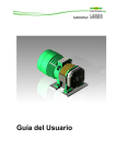
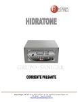
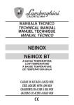
E
S
P
A
Ñ
O
L
1
SMC
Página
1 Introducción………………………………………………………………3
2 Descripción del aparato……………………………….…………. 4
3 Instalación…………………. ………...………………..…………….. 5
4 Preparación del agua…………………………………………….. 7
5 Adición de la sal……………………………………………………... 8
6 Operación………………………….…………………………………… 9
7 Recomendaciones y advertencias.........................12
8 Limpieza manual de la célula…………………………………. 13
9 Garantía, servicio postventa
y piezas de repuesto…………………………………………….. 14
10 Características técnicas…………….……..……….…………. 15
Reservados todos los derechos
SMC
2
1. INTRODUCCIÓN
Le agradecemos la confianza que ha depositado en nosotros con la adquisición
de su clorador Innowater. Los cloradores SMC han sido fabricados siguiendo el
más estricto control de calidad y utilizan la tecnología más avanzada en
electrolisis salina, fruto de nuestra experiencia e investigación durante más de
20 años.
Con un mínimo de mantenimiento y un respeto de las normas elementales de
instalación e utilización usted disfrutará de un aparato extremadamente eficaz
durante muchos años.
Les rogamos que lea atentamente este manual antes de su instalación o puesta
en marcha y que lo conserve para futuras referencias.
Los apartados que conciernen la instalación suponen un cierto conocimiento
técnico de la piscina. Le aconsejamos que recurra a un profesional.
Ponga especial atención en los puntos marcados con el símbolo:
Los daños causados al aparato por no respetar estas precauciones pueden
suponer la anulación de la garantía.
3
SMC
E
S
P
A
Ñ
O
L
3. INSTALACIÓN
E
S
P
A
Ñ
O
L
Cuadro de mando
Fije el cuadro de mando utilizando el soporte posterior y los tornillos
suministrados en un lugar de fácil acceso y lectura. El cuadro de mando deberá
situarse a 1,5 metros como máximo de la célula electrolítica. Elija un lugar bien
ventilado y protegido de posibles salpicaduras de agua o inundaciones.
Asegúrese
interruptor
de
que
la
diferencial.
instalación
Esto
es
está
protegida
imperativo
por
un
y
es
legal
fundamental para su seguridad.
Conecte el hilo de tierra (amarillo y verde) del extremo del cable de
alimentación a la tierra del cuadro de la piscina. Conecte la fase (marrón) y el
neutro (azul) a la salida 220 VAC del contactor de la bomba de forma que el
clorador sea alimentado cuando se enciende la bomba. Conecte el clorador
sobre bornes libres. No utilice las bornes ocupados por los hilos de la
bomba. Esto evitará que, al cortar la corriente, el clorador quede unido
eléctricamente a la bomba lo que podría ocasionar daños graves. Compruebe
que el clorador se apaga cuando la bomba se para. Esta operación debe ser
efectuada por un profesional.
El clorador debe recibir 220 VAC sólo cuando la bomba está
conectada y el agua circula por la célula. Ponga especial
atención si su instalación es trifásica (bomba a 380 VAC)
Vaso de célula
El vaso de la célula debe ser instalado en el retorno de agua a la piscina y debe
ser el último elemento por el que pasa el agua antes de volver a la misma:
Siempre después del filtro y, en su caso, de la bomba de calor, paneles solares
5
SMC
etc. Utilice pegamento para PVC rígido y espere a que se haya secado
completamente antes de introducir la célula.
Si ha instalado un sistema de regulación automática de pH, la
inyección
del
producto
debe
realizarse
imperativamente
después del vaso. De lo contrario los electrodos de la célula
sufrirían una fuerte corrosión al contacto con el ácido y su
garantía quedaría anulada. No sitúe el bidón de ácido en un
local
técnico
insuficientemente
ventilado
para
evitar
la
sulfatación de componentes electrónicos.
Cuando sea posible, se recomienda la instalación en by-pass con tres válvulas.
Esta disposición permite ajustar la cantidad de agua que circula por la célula y
poder utilizar la depuradora con la célula desmontada. En cualquier caso,
cuando se dispone de una bomba de cierta potencia, el by-pass es necesario
para reducir la velocidad del agua a su paso por el célula y evitar vibraciones y
presión excesiva en los electrodos.
Puede instalar el vaso vertical u horizontalmente, según las posibilidades de su
local técnico, si bien la posición vertical es la más recomendable. Esta posición
permite, además, el desalojo de la célula sin derrame de agua. EL AGUA DEBE
ENTRAR POR EL CONDUCTO LATERAL. Prevea suficiente espacio para poder
desenroscar la rosca y extraer la célula una vez que haya instalado el vaso.
No instale nunca la célula con la entrada de agua lateral
mirando hacia arriba.
SENTIDO
CORRIENTE
DE AGUA
SMC
6
Célula
Introduzca la célula en el vaso. LA ABERTURA LATERAL DEBE COINCIDIR
CON LA ENTRADA DE AGUA DEL VASO. Asegúrese de que la junta se
encuentra en su lugar y coloque la rosca. A continuación, conecte el cable de la
célula en los bornes de la célula. Verifique que el orificio más pequeño del
conector se encuentra alineado con la varilla pequeña en la célula.
NOTA: Los bornes deben ser apretados sólo ligeramente y siempre a mano. No
utilice nunca una herramienta porque podría dañar la célula. La estanqueidad
de la célula está asegurada por el sellado interior.
Una buena filtración es fundamental para la cloración salina.
Verifique que su filtro y elementos filtrantes están en óptimas
condiciones de trabajo.
4. PREPARACIÓN DEL AGUA
Utilice preferentemente agua de la red urbana. Si utiliza agua de origen distinto
hágala analizar primero y verifique que no existe ninguna contraindicación para
la electrólisis salina (como, por ejemplo, una concentración elevada de metales
o cal). Compruebe también que el agua es conforme a las normas sanitarias.
Equilibre el agua antes de poner en funcionamiento su clorador y añada
estabilizador en la cantidad prescrita por el fabricante (normalmente 1 kg por
cada 25m3 de agua). No añada demasiado estabilizador porque bloqueará la
acción desinfectante del cloro.
NOTA : El estabilizador impide la desintegración del cloro debida a los rayos
UV. La ausencia de estabilizador puede dificultar la obtención de un residual de
cloro en horas de máxima insolación y le obligará a producir más cloro
inútilmente reduciendo la vida de la célula. En general, y especialmente si no
7
SMC
E
S
P
A
Ñ
O
L
tiene estabilizador, le recomendamos clorar cuando no haya sol.
El agua debe estar limpia y clara y presentar los siguientes parámetros:
5-6 kg/m3 (gr/l)
Sal
pH
7,2-7,6 (cemento) 6,8-7,0 (poliéster)
TAC
60-100 ppm
TH
15-20º Franceses
Estabilizador
1 kg por cada 25m3 de agua (o según indicación
del fabricante)
Temperatura
>10 º C
5. ADICIÓN DE LA SAL
El clorador debe permanecer totalmente desconectado durante
esta
operación
y
hasta
que
la
sal
haya
sido
disuelta
completamente. El funcionamiento del clorador con sal sin
disolver podría dañar irreversiblemente la célula y la fuente de
alimentación y la garantía quedaría anulada.
Calcule el volumen de la piscina y vierta de 5 a 6 kg de sal por metro cúbico.
Asegúrese de que el clorador está desconectado y haga funcionar la depuradora
durante al menos 24 horas antes de conectar el clorador.
Espere
cuatro
semanas
antes
de
verter
sal
sobre
un
revestimiento reciente de cemento.
Puede acelerar el proceso de disolución de la sal utilizando el limpia fondos.
Compruebe con un kit de medida del comercio que la concentración de sal se
encuentra entre 5 y 6 kg/m3.
El funcionamiento del clorador no conlleva ningún consumo de sal. Con el
tiempo, sin embargo, la concentración de sal puede verse reducida a causa de
la lluvia o de otros aportes de agua dulce (relleno, lavado del filtro). Cuando
tenga que corregir la concentración de sal, vierta la sal lo más cerca posible de
los impulsores. Nunca en los skimmers o en el sumidero.
SMC
8
6. OPERACIÓN
El clorador y sus diferentes menus se controlan mediante un teclado de cuatro
teclas. Dos de ellas Λ y MENU tienen una doble función a la que se accede
presionando la tecla durante 2 segundos.
NOTA: El algunos momentos de la actividad del clorador puede que el teclado
no responda inmediatamente y la pantalla tarde unos segundos en responder.
Esto es completamente normal.
6.1 ON/OFF
OFF
La tecla ON/OFF (tecla MENU + 2 segundos) apaga y enciende
alternativamente el clorador. Una vez en ON se mostrará la siguiente pantalla:
Produccion: 70%
Sal:
OK
En ella se indica el nivel de producción actual y el nivel de sal existente. El nivel
de sal puede tardar en aparecer unos segundos. Si se encuentra en otra
pantalla puede siempre volver a la pantalla de producción pulsando varias
veces la tecla MENU.
Para aumentar o disminuir el porcentaje de producción actúe sobre las flechas
Λ o V. La producción se controla variando el tiempo de funcionamiento en
periodos de 10 minutos. Al 100% el clorador trabaja en continuo.
En principio, usted llegará a conocer las necesidades de su piscina en función
de las distintas condiciones (número de bañistas, temperatura, etc.) lo que le
permitirá anticiparse en el ajuste. En general, para disfrutar de las ventajas de
la cloración salina, le recomendamos que ajuste la producción al mínimo
porcentaje que produzca un agua limpia y cristalina en su piscina. Evite clorar
durante las horas de mayor insolación porque el cloro generado desaparecerá
rápidamente con los rayos UV y no tendrá tiempo para desinfectar su piscina en
profundidad. Le recomendamos programar la depuradora por la noche, al
amanecer o al atardecer.
6.2 Función Shock
La función Shock le permite aplicar un tratamiento de choque (clorador al
100%) durante un número de horas y que el clorador vuelva a su estado de
producción anterior sin necesidad de que vuelva a ajustarlo. Esta función es útil
9
SMC
E
S
P
A
Ñ
O
L
si el nivel de cloro ha disminuido bruscamente debido a alguna causa y quiere
recuperarlo rápidamente.
Para activar la función shock debe estar en la pantalla de producción y pulsar la
tecla Λ (SHOCK) durante unos segundos. Aparecerá la siguiente pantalla:
Shock
7 horas
Selecc. duracion
Seleccione un número de horas, mediante las
teclas Λ V y pulse OK para aceptar o MENU
para salir. Si pulsa OK, el clorador entrará en la
función Shock y mostrará la siguiente pantalla:
SHOCK
7 horas
Quedan:
07:00
Anular Shock?
SI:OK NO:MENU
Para abandonar la función Shock pulse cualquier
tecla. Aparecerá la pantalla de la izquierda. Pulse
OK para abandonar la función shock o MENU
para volver a ella.
6.3 Menús
Para acceder a los diferentes menus, pulse la tecla MENU desde la pantalla de
producción. Aparecerá la siguiente pantalla:
MENU PRINCIPAL
1 Idioma
Desplácese a continuación con las flechas Λ o V
hasta el menú deseado y pulse OK para acceder
a él. Para regresar a la pantalla de producción
pulse la tecla MENU varias veces.
6.3.1 MENU PRINCIPAL 1 Idioma
Elija idioma
Español
Desplácese con la flechas Λ V hasta encontrar el
idioma deseado y pulse OK. Vuelva a pulsar
MENU para regresar a la pantalla de producción.
6.3.2 MENU PRINCIPAL 2 Periodo de polaridad
La polaridad aplicada a la célula se invierte periódicamente para desincrustar
posibles depósitos de cal. La programación de fábrica es cada 8 horas.
Dependiendo de las condiciones de su piscina puede ser necesario disminuir
este periodo para aumentar la frecuencia de limpiado. Tenga en cuenta que
cuanto menor sea este periodo menor será la duración de su célula. Un
periodo de menos de 4 horas reducirá drásticamente la duración de la célula.
SMC
10
Inversamente, puede que su piscina necesite una frecuencia menor de limpieza
y puede aumentar el periodo de fabrica. Le recomendamos ajustar siempre este
periodo al mayor número de horas posible mientras no observe incrustaciones
calcáreas en la célula.
Selecc. periodo
polaridad 8 h.
Cambio polaridad
Espere 06:30
Seleccione el periodo de polaridad mediante las
flechas Λ ó V y pulse OK para confirmar y
guardar el valor o bien MENU para salir.
Cuando se produce el cambio de polaridad el
aparato entra en modo de espera durante unos
10 minutos. Esto se indicará con la pantalla de
la izquierda.
6.3.3 MENU PRINCIPAL 3 Valores T V I
T= 30,3ºC
V=23,40V I=3,20A
Este menú visualiza la temperatura en la unidad
de control y el voltaje e intensidad en la célula.
Estos parámetros pueden ser muy útiles para
diagnóstico.
6.3.4 MENU PRINCIPAL 4 Contraste LCD
Ajuste contraste
- ■ ■ ■ ■
+
Ajuste el contraste mediante las teclas Λ V y
pulse OKpara confirmar.
6.3.5 Mensajes de fallo
NIVEL BAJO DE
AGUA EN CELULA
Esta pantalla aparece cuando la sonda no detecta agua y el sistema de control
detiene la producción. Verifique que existe agua en la célula y que su nivel llega
hasta la parte superior donde se encuentra la sonda. Un nivel bajo puede
producirse por hacer funcionar el clorador sin que la bomba esté funcionando
en cuyo caso ha de apagarse inmediatamente el aparato.
EL CLORADOR NO DEBE CONECTARSE NUNCA SI LA BOMBA NO FUNCIONA O
SI EL AGUA NO CIRCULA SUFICIENTEMENTE. SU ALIMENTCION ELECTRICA
DEBE DEPENDER DE LA ALIMENTACION DE LA BOMBA. VER PAGINA 5.
Un nivel bajo de agua en la célula puede también ser debido a un filtro sucio,
11
SMC
E
S
P
A
Ñ
O
L
una obstrucción en el circuito o a una bomba de potencia insuficiente. Tan
pronto como el nivel de agua se restituye desaparece el fallo.
NIVEL DE SAL
INSUFICIENTE
Esta pantalla aparece cuando la concentración de sal en el agua es demasiado
baja y el clorador detiene la producción para evitar daños en la célula. Añada
sal en suficiente cantidad (de 5 a 6 kg/m³) y cuando se haya disuelto
completamente pulse la tecla OK para reiniciar el aparato.
Esta pantalla puede también aparecer si la temperatura del agua es
excesivamente baja, si hay una mala conexión eléctrica entre el cuadro de
mando y la célula o si existen depósitos de cal en los electrodos.
7. RECOMENDACIONES Y ADVERTENCIAS
Las células bipolares de su clorador SMC
han sido fabricadas utilizando una
técnica exclusiva y un riguroso control de calidad que les confiere una duración
y resistencia extraordinarias. No obstante, existen diversos factores que
pueden mermar irreversiblemente las propiedades de cualquier electrodo y que
usted deberá evitar afín de obtener el mayor rendimiento y duración de su
clorador. Estos son:
- Funcionamiento con depósitos de cal en la superficie de los electrodos
- Concentración de cloro excesiva (el cloro es corrosivo por encima de 3.0 ppm)
- pH demasiado alto o bajo
- Ausencia de sal o concentración demasiado baja
- Temperatura del agua inferior a 10º C
- Vertido de la sal con clorador en marcha
-Inyección de ácido corrector de pH antes del vaso, en los
skimmers o sobre el sumidero de fondo.
Le recomendamos inspeccionar periódicamente la célula. El aislante que
recubre las varillas de los electrodos y el sellado superior deben estar en
perfecto estado. Si observa cualquier daño envíe la célula al servicio técnico
para ser examinada.
NO haga funcionar NUNCA el clorador si:
- Su instalación carece de interruptor diferencial
- No circula agua por la célula
SMC
12
- Las válvulas están cerradas
- Esta lavando el filtro
- Está vaciando la piscina
- El agua está congelada
- Los electrodos están obstruidos por la cal
8. LIMPIEZA MANUAL DE LA CÉLULA
Su clorador SMC está dotado de un sistema de auto limpieza por cambio de
polaridad que elimina, prácticamente, el mantenimiento. No obstante, en casos
excepcionales cuando la concentración calcárea del agua es muy elevada
(aguas muy duras), el cambio de polaridad puede no ser suficiente para
eliminar completamente los depósitos calcáreos. Inspeccione visualmente la
célula con regularidad para detectar la presencia de cal y, si es necesario,
limpie la célula. Lo ideal es dejar secar la célula completamente durante uno o
varios días para que se desprendan las placas de cal por si solas. Puede
ayudarlas golpeando ligeramente la célula o con agua a presión pero no
introduzca ningún elemento que pueda rayar los electrodos ya que su
recubrimiento es delicado. Puede utilizar también agua a presión. NO UTILICE
NINGUN ELEMENTO METALICO O PUNZANTE PARA RASCAR LOS ELECTRODOS.
Si le es imposible desprender la cal de esta forma, proceda como sigue:
1 Apague la bomba y el clorador.
2
Desconecte el cable DC de la célula, desenrosque la rosca y extraiga la
célula.
3
Sumerja los electrodos en una solución compuesta por 1 parte de ácido
clorhídrico (HCl 30%) y 9 de agua. No sumerja las varillas ni la tapa donde se
encuentran los bornes. El ácido clorhídrico reaccionará con la cal produciendo
gas.
4 Una vez limpia, aclare inmediatamente la célula con agua dulce, seque bien
el área de los bornes y vuelva a instalarla en el vaso.
No deje la célula nunca más de 5 min. en la solución ácida. No
rasque los electrodos con objetos metálicos. ATENCION: Vierta
siempre el ácido sobre el agua y nunca a la inversa.
13
SMC
E
S
P
A
Ñ
O
L
9. GARANTÍA, SERVICIO POST-VENTA Y PIEZAS DE REPUESTO
Garantía y servicio postventa
1. La célula electrolítica y el cuadro de mandos tienen 3 años de garantía contra
cualquier defecto de fabricación. La célula es un elemento consumible cuyo
desgaste depende de las condiciones de utilización y no está cubierto por la
garantía.
2. El fabricante declina toda responsabilidad en los siguientes casos:
a.
No respetar las instrucciones de este manual
b.
Uso del clorador con obstrucción de cal en la célula
c.
Conexiones eléctricas incorrectas
d.
Daños causados por accidentes
e.
Daños causados por el agua en el cuadro de mandos
f.
Bomba de más de 1,5 CV sin instalación de un “ByPass” (según esquema de montaje de la página 4)
g.
Vertido de ácido en los Skimmers sin desconectar el
clorador
h.
Emplazamiento de bidón de ácido dentro de la caseta
de depuración y/o sala de máquinas con insuficiente
ventilación.
i.
Uso de la célula por debajo de 3.000 ppm de sal
3. Los gastos de envío del clorador serán abonados por el cliente/distribuidor.
4. Innowater hace constar que la instalación del clorador “Innowater” es
completamente independiente del equipo de depuración, tanto de la bomba
como del filtro o de la multiválvula. Lo único que tienen en común es la
conexión al reloj de la depuradora.
Piezas de repuesto
Innowater, s.l. o su distribuidor dispone de piezas de repuesto. El uso de piezas
no originales, así como la manipulación del equipo por personal no autorizado
por “Innowater” puede ocasionar serios problemas a su clorador y anulará la
garantía.
SMC
14
10. CARACTERÍSTICAS TÉCNICAS
SMC10
SMC20
SMC30
Caudal máximo
450 lt/min
450 lt/min
450 lt/min
Presión máxima
4 bar
4 bar
4 bar
Caída de presión
5 kpa
5 kpa
5 kpa
Producción de cloro
10 gr/h
20 gr/h
30 gr/h
Voltaje de salida (máx)
24 VDC
24 VDC
24 VDC
Corriente de salida (máx.)
2,0 amp
3,5 amp
5,0 amp
Tipo de célula
Bipolar
Bipolar
Bipolar
Concentración de sal
recomendada
5-35 gr/l
5-35 gr/l
5-35 gr/l
Material cassette célula
PC
PC
PC
16.000 h
Vida de la célula
16.000 h
16.000 h
Material electrodos
Titanium Grade1
Titanium Grade1 Titanium Grade1
40 m3
90 m3
150 m3
3
3
110 m3
Tamaño máximo piscina :
-Clima templado
-Clima tropical
Alimentación
Consumo max.
Peso
30 m
60 m
220 VAC
220 VAC
220 VAC
80 Watt
190 Watt
200 Watt
3,3 kg
3,5 kg
3,0 kg
15
SMC
E
S
P
A
Ñ
O
L
Page
1 Introduction………………………………………………………….. 17
2 Salt water chlorinator description……………….……... 18
3 Installation…………………………………………………………….. 19
4 Water preparation ...…………………………………………….. 21
5 Adding salt……………………………………………………………
22
6 Operation………………………….…………………………………… 23
7 Recommendations and warnings ........................28
8 Manual cell cleaning ……………………………………….…...29
9 Warranty, technical service and
spare parts......…………………………..……….……………...30
10 Technical characteristics………….…………………………. 31
All Rights Reserved
SMC
16
1. INTRODUCTION
We thank you for the purchase of a Innowater chlorinator. SMC chlorinators are
manufactured following the strictest quality controls and using the most advanced
technology of saltwater electrolysis resulting from our experience and research for
over 20 years.
With minimum maintenance and following elementary rules for installation and use,
you will enjoy an extremely efficient device for many years.
Please read this manual carefully before its installation or start-up, and keep it for
further reference.
The sections concerning the installation require certain technical knowledge on the
swimming pool. We recommend the installation by a professional.
Please pay special attention to the points marked with the following symbol:
Any damage caused to the chlorinator resulting from not complying with these
warnings may lead to cancellation of the warranty.
E
N
G
L
I
S
H
17
SMC
3 INSTALLATION
Control Unit
Mount the control unit on a wall using the bracket on the back and the screws
supplied. Choose a place for easy access and reading. The control unit must be
placed at 1.5 meters max. away from the electrolytic cell. Choose a place with good
ventilation and protected from the rain and possible water leaks or splashing.
Please, make sure that a residual current circuit breaker protects
the installation. This is a legal requirement and very important for
your safety.
Connect the ground wire (yellow and green) from the 220 VAC power supply cable
to the ground of the swimming pool electric panel. Connect the phase (brown) and
the neutral (blue) to the output terminals of the pump contactors in such a way that
the chlorinator will be powered only when the pump is working. Connect the
chlorinator wires to available terminals. Do not use the terminals in use by the
pump. This will prevent the chlorinator to be electrically connected to the pump
when switching off the current what could cause serious damage. Verify that the
chlorinator switches off itself when the pump stops. This operation should be
performed by a professional.
The chlorinator should be powered with 220 VAC only if the pump is
working and the water is flowing through the cell. Please pay
special attention if your installation is three-phase (380 VAC pump)
Cell housing
The cell housing must be installed in the return flow to the swimming pool and as
19
SMC
E
N
G
L
I
S
H
the last element the water goes through before returning to the pool: always after the
filter and any the heat pumps, solar panels, etc. Use special glue for rigid PVC and wait
until it completely dries before inserting the cell.
If an automatic pH regulation system has been installed, the
injection of the product must take place unconditionally after the
cell. Otherwise, the electrodes will corrode due to the acid contact
and the warranty will be cancelled. Do not place the acid tank near
the chlorinator with insufficient ventilation. The gases will corrode
the electronic components quickly.
Whenever
it
is
possible,
a
by-pass
installation
with
three
valves
is
always
recommended. This allows the amount of water flowing through the cell to be adjusted
and the swimming pool to work with the cell housing disassembled. In any case, when
there is a pump with certain power, the by-pass is necessary to reduce the speed of
water through the cell housing to lower the pressure and avoid vibrations.
Although the vertical position is recommended, the cell housing may be installed
vertically or horizontally, according to the characteristics of your site. The vertical
position also allows for dissembling the cell without water spillage. Provide enough room
to unscrew the thread and extract the cell once the housing has been installed. WATER
MUST ENTER THE CELL THROUGHT THE SIDE WATER INLET TUBE.
NEVER INSTALL THE CELL WITH ITS SIDE WATER INLET FACING
UPWARDS
WATER
FLOW
SMC
20
Cell
Insert the cell in the cell housing making sure that its side open window is facing
the side water inlet. Make sure the O ring is fitted correctly and tighten the thread.
Then, connect the cell cable connector to the cell terminals. Verify that the small hole
is aligned with the thin pin before trying to plug the connector.
NOTA: The cell pins should only be tighten slightly and always by hand. Never use a
tool because the cell could be damaged. Water tightness is assured by the internal
seal.
A good filtration is essential in salt chlorination. Please, verify that
your filter and filtrating material are in optimal working conditions.
4. WATER PREPARATION
Use preferably water from the metropolitan network. If water from a different origin
is used, have it analyzed and verify so that there is no contraindication regarding
salt electrolysis (such as a high concentration of metals or calcium, for example).
Make also sure the water complies with health standards.
Balance the water before starting your chlorinator and add the amount of chlorine
stabilizer prescribed by the manufacturer (normally 1 kg per 25m3 of water). Do not
exceed the dose because this will block the disinfection action of the chlorine.
NOTE : Stabilizer prevents the disintegration of chlorine due to UV radiation. The
lack of stabilizer could make it difficult to reach a chlorine residual concentration
during high sunshine periods and will oblige you to produce more chlorine reducing
the life span of your cell. In general, and specially if you don't use stabilizer, we
recommend to chlorine during the night or at sunrise or evening.
21
SMC
E
N
G
L
I
S
H
The water must be clean and clear, presenting the following parameters:
Salt
5-6 kg/m3 (gr/l)
pH
7,2-7,6 (cement) 6,8-7,0 (polyester)
TAC
60-100 ppm
TH
15-20º French
Stabilizer
1 kg per 25m3 of water (or according to the indications
by the manufacturer)
Temperature
>10 º C
5. ADDING SALT
The chlorinator must remain totally disconnected during this operation
and until the salt is completely dissolved. Operating the chlorinator
with non dissolved salt could irreversibly damage the cell and the
power supply, and lead to a cancellation of the warranty.
Calculate the volume of the swimming pool and add 5 to 6 Kg of salt per cubic meter.
Make sure the chlorinator is disconnected and make the filtration system to work for at
least 24 hours.
Wait for four weeks before adding salt into a recent cement coated
pool.
The salt dissolving process can be accelerated using the pool cleaner. Check the salt
concentration is between 5 and 6 kg/m3 using a kit from a specialized pool shop.
The salt chlorination process don’t consume salt. However, the salt concentration may
be reduced over time due to the rain or other periodic freshwater contributions (filling
up, filter cleaning, etc.). Whenever the salt concentration needs to be corrected, pour
salt as close as possible to the return lines. Never pour salt in the skimmers or in the
drain inlet.
SMC
22
6. OPERATION
The chlorinator and its different menus are controlled with a four key keypad. Three
of these keys, Λ , MENU and OK, also have a secondary function accessible by
pressing and holding down the corresponding key for 2 seconds
NOTE: At some points of activity or during a change of function the keyboard may
seem as it is not responding immediately. This is completely normal. Just wait a few
seconds for the task to be completed and the display will respond.
OFF
The ON/OFF function (MENU key + 2 seconds) turns the chlorinator alternatively
ON and OFF. Once switched on, the main production screen will appear:
Production: 70%
Salt:
OK
This screen indicates the current production rate and the existing salt level in the
water. It may take a few seconds for the salt level to appear. If you are on a different
screen you can always come back to the production screen by pressing the MENU
button repeatedly.
To increase or decrease the chlorine production rate press the Λ or V arrows. The
production is controlled by varying the operating time in periods of 10 minutes. At
100% the chlorinator works constantly.
You will get to know the needs of your pool which will depend on the different
conditions (number of users, temperature, etc.) allowing you to anticipate in the
setting. In general, to enjoy the benefits of salt water chlorination, we recommend
setting the minimum production rate that produces a crystal clear water in your pool.
Avoid chlorinating during high sunshine hours because chlorine will quickly disappear
due to the UV radiation and won’t have the time to disinfect your pool thoroughly.
We recommend to program the chlorinator during the night or at sunrise.
Shock Function
The shock function allows you
selectable period of time with
the shock period has ended.
suddenly for some reason and
to apply a shock treatment (chlorinator at 100%) for a
automatic return to the previous production rate once
This feature is useful if the chlorine level has fallen
you want to recover it quickly.
To activate the shock, go to the production screen and press Λ SHOCK for a few
seconds. The following screen will appear:
Shock
7 h
Select duration
23
SMC
E
N
G
L
I
S
H
Select a number of hours, by using the Λ or V arrows and press OK to accept or MENU
to exit. If you click OK, you will enter the Shock function and the following screen will
be displayed:
SHOCK
7 h
Remaining: 07:00
If you want to quit the Shock function press any key. The following screen will be
displayed:
Cancel Shock?
YES:OK NO:MENU
Press OK to exit the shock function or MENU to continue
the shock treatment.
1 Language setting
From the main screen press MENU. The following screen will appear:
MAIN MENU
1 Language
Choose language
English
Press OK to enter the Language menu.
Choose a language using he arrows Λ V and confirm by
pressing OK. Press MENU to return back to the
production screen.
2 Polarity period setting
The polarity applied to the cell is periodically reversed to remove calcium built-up. The
factory pre-programmed period is 8 hours. Depending on the conditions of your pool it
may be necessary to reduce this period in order to increase the frequency of cleaning.
Note that the longer this period is, the longer the cell duration will be. A period
of less than 4 hours will drastically reduce the life of the cell. Inversely, you can
increase this period if your cell don’t need to be cleaned that frequently. We
recommend, in general, to set this period to the larger number of hours as long as there
is not calcium build-up on the electrodes.
To change the polarity period, go to the production screen and press MENU. The
following screen will appear:
MAIN MENU
1 Language
SMC
Press the Λ or V buttons until you reach the menu 2
Polarity period as shown in the following screen:
24
MAIN MENU
2 Polarity per.
Press OK. The following screen will be displayed:
Polarity
7h
Select period
Use the Λ or V buttons to select the period and then press OK to confirm and save
the setting. Then press MENU once or more to return to the production screen. You
can also exit without saving the setting by pressing MENU.
Chang. polarity
remaining: 8 min
When a polarity change is taking place the unit will
enter a pause mode during 10 minutes. This will be
indicated by the screen on the left.
3. T V I readings
MAIN MENU
4 T V I readings
This menu allows you to read find the temperature
inside the control unit, the voltage applied to the
cell and the current passing through it. These
parameters can be very useful when servicing or
diagnosing.
T= 29.8ºC
V= 23.40V I=3.4A
4. LCD contrast
MAIN MENU
6 LCD contrast
LCD contrast
- ■ ■ ■ ■ ■ ■ +
Go to the MENU 6 LCD contrast and press OK
Adjust the LCD contrast using the Λ V keys.
Press OK to save and exit.
5. Fault messages
LOW WATER
LEVEL IN CELL
25
SMC
E
N
G
L
I
S
H
This screen is displayed when the probe detects no water and the control
system stops the production. Verify that there is water in the cell and that its
level reaches the top where the probe is located. A low water level can result
from operating the chlorinator with the pump not turning. In this case switch
the chlorinator off immediately.
THE CHLORINATOR SHOULD NEVER BE POWERED IF THE PUMP IS NOT
WORKING OR IF THE WATER IS NOT FLOWING SUFFICIENTLY. THE
CHLORINATOR POWER SUPPLY SHOULD DEPEND ON THE PUMP POWER
SUPPLY.
A low water level in the cell may also be due to a dirty filter, an obstructed
circuit or to a pump not powerful enough. As soon as the water level is restored
the fault disappears.
SALT TOO
LOW
This screen appears when the salt concentration in the water is too low to
prevent cell damage. Add enough salt (5 to 6 kg/m³) and wait until the salt is
completely dissolved. Then press OK to restart the chlorinator. This screen can
also be displayed if the water temperature is too low, if there is a bad electrical
connection between the control unit and the cell or if there is calcium built up
on the electrodes.
CELL NOT
DETECTED
This screen appears when the control unit does not detect a celle connected to
it. Make sure the cell is well connected and press OK to restart.
SMC
26
E
N
G
L
I
S
H
27
SMC
7. RECOMMENDATIONS AND WARNINGS
The bipolar cells of your SMC chlorinator have been manufactured using an exclusive
technique and rigorous quality controls conferring extraordinary duration and resistance.
However, there are several factors that may irreversibly reduce the properties of any
electrode that you should avoid in order to obtain the best performance and longest
lifespan of your chlorinator. These are:
- Operating with calcium build up on the electrodes
- Excessive chlorine concentration (chlorine is corrosive above 3.0 ppm)
- pH too low or too high
- Insufficient salt concentration
- Water temperature below 10º C
- Adding salt to the pool with the chlorinator working
- pH corrector acid injection before the cell housing, in the
skimmers or in the bottom drain inlet
We recommend you to periodically check the cell for calcium build up, corrosion or
leakage. The rods insulation and top sealing must be in perfect conditions. If there is
any damaged please send the cell to the technical service for replacement.
NEVER operate the chlorinator if:
- Your installation is not provided with a residual current circuit breaker
- Water is not flowing through the cell
- Valves are closed
- The filter is being cleaned
- The swimming pool is being emptied
- The water is frozen
- Electrodes are blocked by calcium build-up
SMC
28
8. MANUAL CELL CLEANING
Your SMC chlorinator is provided with a self-cleaning polarity change system that in
normal conditions eliminates maintenance work. However, in exceptional cases,
when the calcium concentration is very high (very hard water), polarity change may
not be enough to completely eliminate the calcium build up. Visually inspect the cell
regularly to detect the presence of calcium and, if necessary, clean the cell. Let the
cell dry completely during one or more days for the calcium build up to detach by
itself. You can help this by slightly knocking the cell but do not introduce any element
that could scratch the electrodes. Their coating is fragile. You can also use a water
jet. DO NOT USE ANY METALLIC OR STABBING ELEMENT TO SCRATCH THE
ELECTRODES.
If you are not able to remove the calcium build up in the way described, proceed as
follows:
1 Turn off the pump and the chlorinator.
2 Disconnect the DC cable for the cell, unscrew the thread lock and extract the cell.
3 Immerse the electrodes in a hydrochloric acid solution made from 1 part of acid
(HCl 30%) and 9 parts of water. Do not immerse the rods or the cap of the cell. The
hydrochloric acid will react with the calcium and will dissolve it producing gas.
4
Once the calcium build up has dissolved, rinse the cell immediately with
freshwater, dry the terminal area properly and reinstall the cell in its housing.
Never leave the cell in the acid solution for more than 5 min. Do
not scratch the electrodes with metal objects. For safety reasons,
always add the acid into the water and never inversely.
29
SMC
E
N
G
L
I
S
H
9. WARANTY, TECHNICAL SERVICE AND SPARE PARTS
Warranty
1. The electrolytic cell and the control board will be guaranteed for 3 years against any
manufacturing defect. The cell is a consumable part and whose wear depends on the
operating conditions and is not covered by the warranty.
2.The manufacturer declines any responsability in the following cases:
a. If the instructions in this manual are not followed
b. Faulty electrical connections
c. Accidental damage
d. Damage due to water in the control board
e.
Pump
of
more
than
1.5
V
power
without
installation
of
a
“By-
Pass” (according to assembly diagram on page 4)
f. If acids are poured into the skimmers or cell without having disconnected
the rectifier.
g. Presence of an acid tank near the chlorinator with insufficient ventilation.
h. Operation with calcium built up on the electrodes.
i. Using the chlorinator under 3.000 ppm salt
3. The chlorinator shipping cost will be paid by the client/distributor.
4. It should be clarified that the “Innowater” chlorinator installation is completely
independent from the filtration equipment, pump or multi-valve. All they have in
common is the connection to filtration timer.
Spare parts
Innowater, s.l. or its distributor have spare parts at your disposal. The use of nonoriginal parts or the manipulation of the equipment by personnel not authorised by
Innowater may cause serious problems to your chlorinator and will cancel the warranty.
SMC
30
10. TECHNICAL CHARACTERISTICS
SMC10
SMC20
SMC30
Maximum flow
450 lt/min
450 lt/min
Maximum pressure
320 kpa
320 kpa
320 kpa
Pressure drop
5 kpa
5 kpa
5 kpa
Chlorine production
10 gr/h
20 gr/h
30 gr/h
Output voltage (max)
24 VDC
24 VDC
24 VDC
Output current (máx.)
2,0 amp
3,3 amp
5,0 amp
Cell type
Bipolar
Bipolar
Bipolar
concentration
4-35 gr/l
4-35 gr/l
Cell housing material
PC
450 lt/min
Recommended salt
PC
4-35gr/l
PC
Cell lifespan
16.000 h
16.000 h
Electrode material
Titanium Grade1
Titanium Grade1 Titanium Gr1
16.000 h
Maximum Swimming pool size:
-Temperate climate
40 m3
90 m3
150 m3
-Tropical climate
30 m3
60 m3
110 m3
220 VAC
220 VAC
220 VAC
80 Watt
190 Watt
200 Watt
3,3 kg
3,5 kg
Power supply
Power consumption
Weight
3,0 kg
31
E
N
G
L
I
S
H
SMC
SMC
32