1
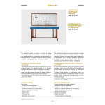
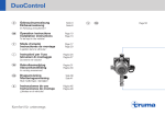
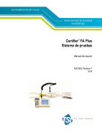
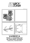
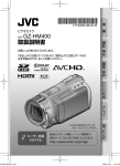
SYSTEMS SIMULATOR
Cat. N. 26-B
SIMULADOR DE SISTEMAS PROGRAMABLES
PROGRAMMABLE
SYSTEMS
SIMULATOR
mod. SSP/EV
SIMULADOR DE
SISTEMAS
PROGRAMABLES
mod. SSP/EV
It is very useful in teaching to simulate different systems and
installations by changing the physical part of the plant, which is
often complicated and bulky but necessary as concerns the
functionality.
The programmable systems simulator mod. SSP/EV, with its
provision of 33 interchangeable masks, reproduces different
installations with sequential and analog control.
By means of simple electrical connections, the process
reproduced on the mask can be interfaced to the inputs and
outputs of the PLC. The processes are represented on the
masks with: led, bargraph, pushbuttons, limit switches, etc.
In the programmable controller, the user writes the control
program or uses the supplied data which he can personalize.
The Programmable Systems Simulator consists of a basic
module which is completed, each time, with the masks
corresponding to the system to be simulated.
It is provided with handbook which includes exercises for each
mask that had been already developed (provided also on
magnetic support) for the PLCs mod. PLC-5A/EV, PLC-5B/EV,
PLC-8/EV and PLC-9/EV.
En un entorno didáctico resulta sumamente útil poder simular
sistemas e instalaciones diferentes, sustituyendo sólo la parte
física de los mismos –a menudo complicada y voluminosa– pero
indispensable desde el punto de vista funcional.
El simulador de sistemas mod. SSP/EV, con su dotación de 33
máscaras intercambiables, reproduce diversas instalaciones con
control de tipo secuencial y analógico.
El proceso que se reproduce en la máscara, a través de simples
conexionados eléctricos, se interfaza con las entradas y las salidas
del PLC; los procesos están representados en las máscaras por
medio de LEDs, barras gráficas, pulsadores, finales de carrera, etc.
El usuario escribe el programa de gestión en el autómata
programable o utiliza los datos en dotación, que en todo caso
podrá personalizar.
Este simulador de sistemas consta de un módulo básico sobre el
cual se colocan, en cada caso, las distintas máscaras
correspondientes al sistema por simular. Está provisto de manual
que contiene –por cada máscara– las prácticas ya desarrolladas
(entregadas también en soporte magnético) para los PLCs mod.
PLC-5A/EV, PLC-5B/EV, PLC-8/EV y PLC-9/EV.
TRAINING PROGRAM
PROGRAMA DE FORMACIÓN
The training program includes the following exercises:
1 - LOGIC PORTS
- Operation of logic ports.
El programa de formación contempla las siguientes prácticas:
1 - PUERTAS LÓGICAS
- Funcionamiento de las puertas lógicas.
2 - DIGITAL FUNCTIONAL MODULE
- Operation of SR and RS flip-flops, TON TOFF TP timers,
counters.
2 - MÓDULOS DIGITALES FUNCIONALES
- Funcionamiento de FLIP-FLOPs SR y RS, temporizadores TON
TOFF TP, contadores.
3 - ASYNCHRONOUS MOTOR STARTING
- Asynchronous motor starting sequence.
3 - ARRANQUE MOTOR ASÍNCRONO
- Secuencia de arranque de un motor asíncrono.
4 - REVERSE OF ASYNCHRONOUS MOTOR
- Control of the motor rotation direction.
4 - INVERSIÓN DE SENTIDO MOTOR ASÍNCRONO
- Control del sentido de rotación del motor.
5 - STAR/DELTA STARTING OF THE ASYNCHRONOUS MOTOR
- Control of the D/U starting sequence at adjustable times
- Resetting the starting conditions at the stop.
5 - ARRANQUE EN ESTRELLA-TRIÁNGULO MOTOR ASÍNCRONO
- Gestión de la secuencia de arranque D/U en tiempos regulables.
- Restablecimiento de las condiciones iniciales tras la parada.
6 - STAR/DELTA REVERSE
- Control of the motor rotation direction.
6 - INVERSIÓN DE SENTIDO EN ESTRELLA-TRIÁNGULO
- Control del sentido de rotación del motor.
7 - POSITION LINEAR CONTROL
- Position control system made by a motor.
7 - CONTROL LINEAL DE POSICIÓN
- Sistema de control de la posición gobernado por un motor.
© Elettronica Veneta & IN.EL. S.p.A.
B3.1
SYSTEMS SIMULATOR
SIMULADOR DE SISTEMAS PROGRAMABLES
8 - DAHLANDER MOTOR STARTING
- Control of the motor HIGH / LOW speeds.
8 - ARRANQUE MOTOR DAHLANDER
- Gestión de la velocidad ALTA/BAJA del motor.
9 - MOTOR WITH TWO SEPARATED COILS
- Control of a motor with two separated coils.
9 - MOTOR CON DOS BOBINAS SEPARADAS
- Control de un motor con dos bobinas separadas.
10 - ASYNCHRONOUS MOTOR STARTING WITH
WOUNDED ROTOR
- Control of the start sequence with 1, 2 or 3 steps
(selectable).
- Resetting the starting conditions at the stop.
10 - ARRANQUE MOTOR ASÍNCRONO CON ROTOR
DEVANADO
- Control de la secuencia de START con 1, 2 ó 3 escalones
(seleccionables).
- Restablecimiento de las condiciones iniciales tras la parada.
11 - CONVEYOR BELTS 1
- Sandy material conveying process controlled with three
conveyor belts.
11 - CINTAS TRANSPORTADORAS 1
- Proceso de transporte de material arenisco, controlado por tres
cintas transportadoras.
12 - REACTIVE POWER COMPENSATION
- Circuit for reactive compensation.
12 - COMPENSACIÓN POTENCIA REACTIVA
- Circuito para la compensación de la potencia reactiva.
13 - RADIATORS
- Control of a heating system.
13 - RADIADORES
- Control de una instalación de calefacción.
14 - SEQUENTIAL LIGHT INSTALLATION
- Control of different sequential starting programs made by 1 to
8 lamps, with single variation of the start up times.
- Operation: AUTO/MAN and UP/DOWN.
14 - LETRERO LUMINOSO SECUENCIAL
- Control de varios programas con encendido secuencial de 1 a 8
lámparas y variación de los tiempos de encendido de cada uno.
- Operación: AUTO/MAN y UP/DOWN.
15 - FILLING SYSTEM 1
- Automatic filling process of test tubes.
15 - SISTEMA DE LLENADO 1
- Proceso automático de llenado de probetas.
16 - FILLING SYSTEM 2
- Filling process of three tanks in line.
16 - SISTEMA DE LLENADO 2
- Proceso de llenado de tres tanques en línea.
17 - CARBON TREATMENT
- Carbon working process.
17 - TRATAMIENTO DEL CARBÓN
- Proceso para el tratamiento del carbón.
18 - EMBOSSING PROCESS
- Embossing process of metal disks controlled with an
electropneumatic system.
18 - PROCESO DE GOFRADO
- Proceso para el estampado en relieve de discos metálicos
gobernado a través del control de un sistema electroneumático.
19 - VENTILATION SYSTEM
- Control of a ventilation system in an underground parking.
19 - SISTEMA DE VENTILACIÓN
- Control de un sistema de ventilación en un aparcamiento
subterráneo.
20 - TRAFFIC LIGHT
- Control of a traffic light to enable road works.
20 - SEMÁFORO
- Control de un semáforo para permitir la realización de los
trabajos de carretera.
21 - TRAFFIC LIGHT FOR PEDESTRIAN CROSSING
- Control of a traffic light on main road with pedestrian crossing.
21 - SEMÁFORO PEATONAL
- Control de un semáforo en una carretera principal con cruce de
peatones.
22 - CONVEYOR BELTS 2
- Serial control of five conveyor belts to convey 4 different
products.
22 - CINTAS TRANSPORTADORAS 2
- Control en serie de cinco cintas transportadoras para el
transporte de cuatro productos diferentes.
23 - CANALIZATION SYSTEM
- Canalization process of two different products.
23 - SISTEMA DE CANALIZACIÓN
- Proceso de canalización de dos productos diferentes.
24 - CONTROL OF THE LEVEL IN A TANK
Control of the tank level in these modes:
- ON/OFF
- Analogic
24 - CONTROL DEL NIVEL DE UN TANQUE
- Gestión del nivel del tanque en modo:
- ON/OFF
- Analógico
25 - REACTOR
- Reaction control through the 3 inputs (substance, inert gas,
catalyst), the refrigerant, the product and the mixer exhaustion.
25 - REACTOR
- Gestión de la reacción con control de tres entradas (sustancia,
gas inerte, catalizador), del refrigerante, de la descarga del
producto y del mezclador.
© Elettronica Veneta & IN.EL. S.p.A.
B3.2
SYSTEMS SIMULATOR
SIMULADOR DE SISTEMAS PROGRAMABLES
26 - CONTROL of a HOIST
- Control of the motion of a hoist at the 4 floors.
26 - MONTACARGAS
- Gestión de un montacargas que funciona en 4 pisos.
27 - FILLING A STORAGE BIN
- Filling process control of a storage bin via 4 pumps.
27 - LLENADO DE UN SILO
- Gestión del proceso de llenado de un silo a través del control de
cuatro bombas.
28 - PUMPING SYSTEM FOR BLACK LIQUORS
- Control of a tank evacuation process from black liquors.
28 - SISTEMA DE BOMBEO DE AGUAS NEGRAS
- Gestión del proceso de vaciado de un tanque con aguas negras.
29 - OPERATION MONITORING OF THREE PUMPS
- Checking the proper operation of three pumps for the level
control inside a tank.
29 - MONITORIZACIÓN DEL FUNCIONAMIENTO DE TRES
BOMBAS
- Gestión del correcto funcionamiento de tres bombas para el
control del nivel en el interior de un tanque.
30 - LEVEL CONTROL OF A TANK VIA PRESSURE
SENSORS
- Control of the level inside a tank using pressure sensors to fix
the height of the water column.
30 - CONTROL DE NIVEL DE TANQUE A TRAVÉS DE
SENSORES DE PRESIÓN
- Gestión del nivel en el interior de un tanque, utilizando sensores
de presión para establecer la altura de la columna de agua.
31 - BEVERAGE DISPENSER
- Simulation of the different sequences of a beverage dispenser.
31 - DISTRIBUIDOR DE BEBIDAS
- Simulación de las diferentes secuencias de un distribuidor de
bebidas.
32 - MECHANICAL MACHINING LINE
- Control of all phases.
- Implementation of different sequences with use of some/all
phases.
32 - LÍNEA DE MECANIZADO
- Gestión de todas las fases.
- Implementación de secuencias diferentes con utilización de
algunas/todas las fases.
33 - MIXER
- Mixing process control of different substances.
33 - MEZCLADOR
- Gestión del proceso de mezcla de sustancias diferentes.
TECHNICAL SPECIFICATIONS
The Programmable System Simulator consists of a panel which
can be used as work unit mounted on a vertical support.
All I/O lines can be connected via safety cables with pin
Ø = 4 mm or via Centronix parallel port. Two potentiometers
enable the selection of the value of the system’s analog
variables, e.g. the filling speed of a storage bin, the
upward/downward speed of a hoist.
CARACTERÍSTICAS TÉCNICAS
Este simulador consta de un panel que puede utilizarse como
unidad de sobremesa o montado sobre un soporte vertical.
Todas las líneas de E/S pueden conectarse a través de cables de
seguridad con terminal Ø = 4 mm o puerto Centronix paralelo.
Dos potenciómetros permiten seleccionar el valor de las variables
analógicas del sistema; por ejemplo, la velocidad de llenado de un
silo, la velocidad de ascenso/descenso de un montacargas.
PROVIDED MASKS
MÁSCARAS EN DOTACIÓN
1 - LOGIC PORTS
1 - PUERTAS LÓGICAS
2 - DIGITAL FUNCTIONAL MODULE
2 - MÓDULOS DIGITALES FUNCIONALES
3 - ASYNCHRONOUS MOTOR STARTING
3 - ARRANQUE MOTOR ASÍNCRONO
4 - REVERSE OF ASYNCHRONOUS MOTOR
4 - INVERSIÓN DE SENTIDO MOTOR ASÍNCRONO
7 - STAR/DELTA STARTING OF THE ASYNCHRONOUS
MOTOR
5 - ARRANQUE EN ESTRELLA-TRIÁNGULO MOTOR
ASÍNCRONO
6 - STAR/DELTA REVERSE
6 - INVERSIÓN DE SENTIDO EN ESTRELLA-TRIÁNGULO
7 - POSITION LINEAR CONTROL
7 - CONTROL LINEAL DE POSICIÓN
8 - DAHLANDER MOTOR STARTING
8 - ARRANQUE MOTOR DAHLANDER
9 - MOTOR WITH TWO SEPARATED COILS
9 - MOTOR CON DOS BOBINAS SEPARADAS
10 - ASYNCHRONOUS MOTOR STARTING WITH
WOUNDED ROTOR
10 - ARRANQUE MOTOR ASÍNCRONO CON ROTOR
BOBINADO
11 - CONVEYOR BELTS 1
11 - CINTAS TRANSPORTADORAS 1
12 - REACTIVE POWER COMPENSATION
12 - COMPENSACIÓN POTENCIA REACTIVA
13 - RADIATORS
13 - RADIADORES
© Elettronica Veneta & IN.EL. S.p.A.
B3.3
SYSTEMS SIMULATOR
SIMULADOR DE SISTEMAS PROGRAMABLES
14 - SEQUENTIAL LIGHT INSTALLATION
14 - LETRERO LUMINOSO SECUENCIAL
15 - FILLING SYSTEM 1
15 - SISTEMA DE LLENADO 1
16 - FILLING SYSTEM 2
16 - SISTEMA DE LLENADO 2
17 - CARBON TREATMENT
17 - TRATAMIENTO DEL CARBÓN
18 - EMBOSSING PROCESS
18 - PROCESO DE GOFRADO
19 - VENTILATION SYSTEM
19 - SISTEMA DE VENTILACIÓN
20 - TRAFFIC LIGHT
20 - SEMÁFORO
21 - TRAFFIC LIGHT FOR PEDESTRIAN CROSSING
21 - SEMÁFORO PEATONAL
22 - CONVEYOR BELTS 2
22 - CINTAS TRANSPORTADORAS 2
23 - CANALIZATION SYSTEM
23 - SISTEMA DE CANALIZACIÓN
24 - CONTROL OF THE LEVEL IN A TANK
24 - CONTROL DEL NIVEL DE UN TANQUE
25 - REACTOR
25 - REACTOR
26 - CONTROL of a HOIST
26 - MONTACARGAS
27 - FILLING A STORAGE BIN
27 - LLENADO DE UN SILO
28 - PUMPING SYSTEM FOR BLACK LIQUORS
28 - SISTEMA DE BOMBEO DE AGUAS NEGRAS
29 - OPERATION MONITORING OF THREE PUMPS
29 - MONITORIZACIÓN FUNCIONAMIENTO DE TRES
BOMBAS
30 - LEVEL CONTROL OF A TANK VIA PRESSURE
SENSORS
30 - CONTROL DE NIVEL DE TANQUE A TRAVÉS DE
SENSORES DE PRESIÓN
31 - BEVERAGE DISPENSER
31 - DISTRIBUIDOR DE BEBIDAS
32 - MECHANICAL MACHINING LINE
32 - LÍNEA DE MECANIZADO
33 - MIXER
33 - MEZCLADOR
DIMENSIONS and WEIGHT
440x297x110 mm – 4.3 kg
DIMENSIONES y PESO
440x297x110 mm – 4,3 kg
PROVIDED ACCESSORIES
• Set of 24 cables with Ø 4-mm pins
ACCESORIOS EN DOTACIÓN
• Juego de 24 cables con terminales Ø 4 mm
POWER SUPPLY
230V – 50-60 Hz
ALIMENTACIÓN
230 V – 50-60 Hz
THEORETICAL-EXPERIMENTAL HANDBOOKS
• Handbook for installation, theoretical-experimental use with
exercises. It includes the application software for the PLCs
with magnetic support.
TEXTOS TEÓRICO-PRÁCTICOS
Manual de instalación, uso teórico-práctico con prácticas. Incluye
el software aplicativo para PLCs en soporte magnético.
MINIMUM PLC REQUIREMENTS
PLC provided with:
- 14 positive logic digital inputs
- 8 24-Vdc digital outputs
- 2 0-10-Vdc analog outputs
- 1 0-10-Vdc analog output
REQUISITOS MÍNIMOS DEL PLC
PLC provisto de:
- 14 entradas digitales lógica positiva
- 8 salidas digitales de 24 Vcc
- 2 entradas analógicas 0-10 Vcc
- 1 salida analógica 0-10 Vcc
SUGGESTED PLC
The systems simulator mod. SSP/EV can be used together with a
standard PLC: mod. PLC-5A/EV, mod. PLC-5B/EV, mod. PLC-8/EV,
PLC-9/EV.
The PLC mod. PLC-9/EV is provided also with the flat cable for
direct PLC – SSP connection.
PLC RECOMENDADO
El simulador mod. SSP/EV puede conectarse con un autómata
modelo comercial PLC-5A/EV, PLC-5B/EV, PLC-8/EV o PLC-9/EV.
Con el PLC mod. PLC-9/EV se suministra un cable plano para el
conexionado directo PLC–SSP.
© Elettronica Veneta & IN.EL. S.p.A.
B3.4
APPLICATIONS
Cat. N. 26-B
APLICACIONES
PAG.
PAGE
APPLICATIONS
B4.1
APLICACIONES
B4.1
Industrial installation
mod. C/EV
B4.3
Instalaciones eléctricas industriales
mod. C/EV
B4.3
Automation of sliding gates
mod. MR/EV
B4.5
Automatización de verjas corredizas
mod. MR/EV
B4.5
Electropneumatic installation
mod. D/EV
B4.7
Instalaciones electroneumáticas
mod. D/EV
B4.7
Trainer for electropneumatic actuators
mod. EAT/EV
B4.11
Entrenador en actuadores electroneumáticos
mod. EAT/EV
B4.11
Robomatic Trainer
mod. RMT/EV
B4.13
Brazo manipulador neumático
mod. RMT/EV
B4.13
3-floor lift
mod. HM400/EV
B4.15
Ascensor de 3 pisos
mod. HM400/EV
B4.15
Automation process with conveyor
mod. TSM-700/EV
B4.17
Proceso de automatización con transportador
mod. TSM-700/EV
B4.17
© Elettronica Veneta & IN.EL. S.p.A.
B4.1
© Elettronica Veneta & IN.EL. S.p.A.
B4.2
APPLICATIONS
Cat. N. 26-B
APLICACIONES
INDUSTRIAL
INSTALLATION
mod. C/EV
INSTALACIONES
ELÉCTRICAS
INDUSTRIALES
mod. C/EV
This system has been designed to enable students to configure and
test a wide range of electrical circuits of increasing complexity, valid
as applications of Programmable Logic Controllers (PLC). It uses
interchangeable modules, so that circuits can be assembled simply
by interconnecting the modules and the PLC using the flexible hoses
provided with the system.
The modules are made in insulating material and include the
graphical representation and the standard electrical symbols of the
components. The connections are eased by standard educational
terminals (Ø 4 mm) with a high degree of protection against
accidental contacts.
The frame mod. TSI/EV (ordered separately) is the main structure
for the lay-out of applications included in the training program.
Este sistema ha sido diseñado y realizado para permitir que los
alumnos implementen, analicen y ensayen una amplia gama de
circuitos eléctricos, de complejidad creciente, válidos como
aplicaciones de los autómatas lógicos programables (PLC). Está
constituido por módulos intercambiables, lo cual permite armar los
diferentes circuitos simplemente conectando los módulos entre sí
y con el PLC mediante cables flexibles en dotación con el sistema.
Los módulos están realizados en material aislante y en ellos está
representado el esquema interno de los componentes y la
simbología eléctrica unificada. Los conexionados están facilitados
por la presencia de terminales didácticos de seguridad (Ø 4 mm)
con alto grado de protección contra los contactos accidentales.
El bastidor mod. TSI/EV (disponible por separado) constituye la
estructura portadora para la realización de las aplicaciones
incluidas en el programa de formación.
INDUSTRIAL INSTALLATION mod. C/EV
The set of modules mod. C/EV has been specifically designed
for the educational experiments of the applications concerning
industrial installation with PLC control mod. PLC-5A/EV,
mod. PLC-5B/EV, mod. PLC-8/EV.
INSTALACIONES ELÉCTRICAS INDUSTRIALES mod. C/EV
El juego de módulos mod. C/EV ha sido diseñado especialmente
para la realización de las prácticas didácticas referentes a las
instalaciones eléctricas industriales controladas por los PLCs
mod. PLC-5A/EV, mod. PLC-5B/EV y mod. PLC-8/EV.
TRAINING PROGRAM
• Control of an electromagnetic contactor from one point
• Pulse control of an electromagnetic contactor
• Independent control of two electromagnetic contactors
• Remote forward/reverse control of induction motor
• Remote/forward reverse control with time delay
• Remote control of a lift (A)
• Star/delta starter
• Starter with stator resistors
• Starter with autotransformer
• Starter with rotor resistors; exclusion with continuous
variation
• Starter with rotor resistors; exclusion with step variation
• Remote pole-changing of a dual-winding motor
• Remote pole-changing of a single-winding motor (Dahlander)
• Counter-current and d.c. current braking
• Control of a circuit breaker
• Drum-switch for direct starting
• Drum-switch for two-speed 2-winding motor
• Drum-switch for forward/reverse control
• Drum-switch for star/delta starting
• Drum-switch for two-speed single-winding
• Control of a lift (B)
PROGRAMA DE FORMACIÓN
• Control de un telerruptor desde un punto
• Control de impulsos de un telerruptor
• Control independiente de dos telerruptores
• Teleinversor de marcha
• Teleinversor de marcha con temporizador
• Mando a distancia de un elevador (A)
• Arrancador en estrella-triángulo
• Arranque mediante resistencias estatóricas
• Arranque mediante autotransformador
• Arranque mediante resistencias rotóricas; exclusión con
variación continua
• Arranque mediante resistencias rotóricas; exclusión con
variación por escalones
• Teleconmutador de polaridad para motor con dos bobinados
• Teleconmutador de polaridad para motor con un solo
arrollamiento (Dahlander)
• Frenado en contracorriente y de corriente continua
• Control de un aislador
• Manipulador interruptor
• Manipulador conmutador
• Manipulador inversor
• Manipulador arrancador en estrella/triángulo
• Manipulador conmutador de velocidad
• Control de un elevador (B)
© Elettronica Veneta & IN.EL. S.p.A.
B4.3
APPLICATIONS
•
•
•
•
•
APLICACIONES
Switching-on of a sequential advertising sign
Remote star/delta starter + forward/reverse control
Emergency/reserve power supply
Traffic light installation
Basic control of a crane
•
•
•
•
•
Encendido secuencial de letreros luminosos
Teleinversor, arrancador en estrella/triángulo
Línea eléctrica de alimentación de reserva/emergencia
Instalación de semáforo
Control de una grúa
TECHNICAL SPECIFICATIONS
The set of modules for industrial installation mod. C/EV consists of:
• 1 Module type AZ-10
5 fuse-holders with 4/6-A sectionable fuses
• 1 Module type AZ-15
1 transformer 115-230 / 12-24 V 50-60 Hz 72 VA
• 4 Modules type AZ-41
1 electromagnetic contactors for industrial uses, 24-Vac coil
• 6 Modules type AZ-42
1 time-delay relay 1.5 - 30 s, 24-Vac coil
• 3 Modules type AZ-43
1 auxiliary relay for industrial uses– 24-Vac coil
• 2 Modules type AZ-44
3 push-buttons for industrial uses
• 2 Modules type AZ-46
3 lamp-holders for industrial uses with 24-V lamps
• 1 Module type AZ-47
1 three-phase Graetz-bridge 600 V 25 A max.
• 2 Modules type AZ-48
1 thermal relay for industrial uses with NO-NC contacts
• 2 Modules type AZ-49a
1 microswitch for industrial uses
• 2 Modules type AZ-49b
1 microswitch for industrial uses (type MBB)
• 2 Modules type AZ-49c
1 microswitch for industrial uses (type BBM)
• 1 Module type AZ-50
1 3-pole drum-switch, 16 A 400 V
• 1 Module type AZ-51
1 3-pole drum-switch (commutator), 16 A 400 V
• 1 Module type AZ-52
1 3-pole drum switch (reverser) 16 A 400 V
• 1 Module type AZ-53
1 star-delta starter switch 16 A 400 V
• 1 Module type AZ-54
1 3-pole drum-switch (pole-changing for Dahlander motors)
16 A 400 V
• 1 Module type AZ-55
3 three-phase terminal boards for power circuits
• 1 Module type AZ-56
9 terminal boards for switching/connection of control circuits
• 1 Traffic light unit mod. TL-1
1 miniature traffic light with 12 24-V lamps
CARACTERÍSTICAS TÉCNICAS
El juego de módulos para realizar las instalaciones eléctricas
industriales mod. C/EV está constituido por:
• 1 Módulo tipo AZ-10
5 portafusibles de panel con fusibles aislables 4/6 A
• 1 Módulo tipo AZ-15
1 transformador 115-230/12-24 V 50-60 Hz 72 VA
• 4 Módulos tipo AZ-41
1 contactor electromagnético para usos industriales, bobina 24 Vca
• 6 Módulos tipo AZ-42
1 temporizador 1,5 - 30 s, bobina 24 Vca
• 3 Módulos tipo AZ-43
1 relé auxiliar para usos industriales – bobina 24 Vca
• 2 Módulos tipo AZ-44
3 pulsadores para usos industriales
• 2 Módulos tipo AZ-46
3 portalámparas para usos industriales con lámparas 24 V
• 1 Módulo tipo AZ-47
1 puente de Graetz trifásico 600 V 25 A máx.
• 2 Módulos tipo AZ-48
1 relé térmico para usos industriales con contactos NA-NC
• 2 Módulos tipo AZ-49a
1 microinterruptor para usos industriales
• 2 Módulos tipo AZ-49b
1 microinterruptor para usos industriales (tipo MBB)
• 2 Módulos tipo AZ-49c
1 microinterruptor para usos industriales (tipo BBM)
• 1 Módulo tipo AZ-50
1 interruptor manipulador tripolar 16 A-400 V
• 1 Módulo tipo AZ-51
1 manipulador conmutador tripolar 16 A-400 V
• 1 Módulo tipo AZ-52
1 manipulador inversor tripolar 16 A-400 V
• 1 Módulo tipo AZ-53
1 manipulador arrancador en estrella/triángulo 16 A-400 V
• 1 Módulo tipo AZ-54
1 manipulador tripolar (conmutador de polaridad para motores
Dahlander) 16 A-400 V
• 1 Módulo tipo AZ-55
3 cajas de bornes trifásicos para circuitos de potencia
• 1 Módulo tipo AZ-56
9 cajas de bornes para conmutación/conexión circuitos de control
• 1 Unidad semáforo mod. TL-1
1 semáforo en miniatura con 12 lámparas de 24 V
ACCESSORIES
Frame TSI/EV. It is carried out with aluminum and sheet steel
sections, chemically treated and painted with epoxy paint. The frame
base is provided with feet needing no fixing element to the table.
ACCESORIOS
Bastidor mod. TSI/EV. Está realizado en aluminio perfilado y chapa de
acero tratados químicamente y pintados con varias manos de barniz
epoxi. La base del bastidor está provista de patas transversales y no
requiere dispositivos de sujeción a la mesa de soporte.
Dimensions: 1000x500x800 mm
Weight: 10 kg
Dimensiones: 1100x500x800 mm
Peso: 10 kg
Set of 60 cables with Ø 4-mm safety pins
Juego de 60 cables con terminales de seguridad Ø 4 mm
POWER SUPPLY: 3x400 (3x230 V)/PE – 50-60 Hz
ALIMENTACIÓN ELÉCTRICA: 3x400 (3x230 V)/PE 50-60 Hz
THEORETICAL-EXPERIMENTAL HANDBOOKS
• Theoretical-application handbook for equipment presentation
• Handbook for the applications with PLC-5A/EV, PLC-5B/EV, PLC-8/EV
TEXTOS TEÓRICO-PRÁCTICOS
• Manual teórico-aplicativo de presentación del equipo
• Manual de las aplicaciones con PLC-5A/EV, PLC-5B/EV, PLC-8/EV
© Elettronica Veneta & IN.EL. S.p.A.
B4.4
APPLICATIONS
Cat. N. 26-B
APLICACIONES
AUTOMATION
OF SLIDING
GATES
mod. MR/EV
AUTOMATIZACIÓN
DE VERJAS
CORREDIZAS
mod. MR/EV
This system has been designed to enable the students to
configure and test a wide range of electrical circuits of
increasing complexity, valid as applications of Programmable
Logic Controllers (PLC). It uses interchangeable modules, so
that different circuits can be assembled simply by
interconnecting the modules and the PLC using the flexible
hoses provided with the system.
The modules are made in insulating material and include the
graphical representation and the standard electrical symbols of
the component. The connections are eased by standard
educational terminals (Ø 4 mm) with a high degree of protection
against accidental contacts.
The frame mod. TSI/EV (ordered separately) is the main
structure for the lay-out of the applications included in the
training program.
Este sistema ha sido diseñado y realizado para permitir que los
alumnos implementen, analicen y ensayen una amplia gama de
circuitos eléctricos, de complejidad creciente, válidos como
aplicaciones de los autómatas lógicos programables (PLC). Está
constituido por módulos intercambiables, lo cual permite armar los
diferentes circuitos simplemente conectando los módulos entre sí
y al PLC mediante cables flexibles en dotación con el sistema.
Los módulos están realizados en material aislante y en ellos está
representado el esquema interno de los componentes y la
simbología eléctrica unificada. Los conexionados están facilitados
por la presencia de terminales didácticos de seguridad (Ø 4 mm)
con alto grado de protección contra los contactos accidentales.
El bastidor mod. TSI/EV (disponible por separado) constituye la
estructura portadora para la realización de las aplicaciones
incluidas en el programa de formación.
AUTOMATION OF SLIDING GATES mod. MR/EV
The system mod. MR/EV is provided with a set of modules
located on the frame mod. TSI/EV, connected between them
and to the PLC, that are the necessary tool to develop an
application much used in domestic installation: the
automation of a sliding gate.
The system constitutes, so, an application of the PLC:
PLC-5A/EV, PLC-5B/EV, PLC-8/EV.
AUTOMATIZACIÓN DE VERJAS CORREDIZAS mod. MR/EV
El sistema mod. MR/EV está constituido por un conjunto de
módulos que al ser colocados en el bastidor mod. TSI/EV,
conectados entre sí y al PLC, constituyen el instrumento
indispensable para el desarrollo de una aplicación sumamente
difundida en el ámbito de las instalaciones domésticas: la
automatización de una verja corrediza.
El sistema constituye de esta forma una aplicación de los PLCs:
PLC-5A/EV, PLC-5B/EV y PLC-8/EV.
© Elettronica Veneta & IN.EL. S.p.A.
B4.5
APPLICATIONS
APLICACIONES
TRAINING PROGRAM
System for automated control of a gate via PLC (remote control
station), crossing sensors and mechanical driving unit with limit
switches.
PROGRAMA Dl FORMACIÓN
Automatización completa, con PLC, de una verja corrediza
completa control remoto, sensores fotoeléctricos de cruce, grupo
de manipulación con motor monofásico asíncrono.
TECHNICAL SPECIFICATIONS
The set of modules for the automation of sliding gates mod.
MR/EV consists of:
• 1 Module type AZ-15
1 transformer 115-230 / 12-24 V 50-60 Hz 72 VA
• 2 Modules type AZ-41
1 electromagnetic contactor for industrial uses, 24-Vca coil
• 1 Module type AZ-187a
1 electronic control board for gate automation with radio
control card
• 1 Module type AZ-187b
1 pair of photoelectric crossing sensors
• 1 Module type AZ-187c
1 intermitting warning light for gate automation with built-in
receiving antenna
• 1 Module type AZ-187d
1 mechanical driving unit with single-phase motor and limit
switches
• 1 Module type AZ-188
1 2-way switch for domestic uses, 2 pushbuttons with 1 NO
contact, 1 pushbutton with 1 NC contact
CARACTERÍSTICAS TÉCNICAS
El juego de módulos para la automatización de verjas corredizas
mod. MR/EV está constituido por:
• 1 Módulo tipo AZ-15
1 transformador 115-230 V/12-24 V 50/60 Hz 72 VA
• 2 Módulos tipo AZ-41
1 contactor electromagnético para usos industriales, bobina 24 Vca
• 1 Módulo tipo AZ-187a
1 centralita electrónica para automatizar las verjas con tarjeta de
control remoto
• 1 Módulo tipo AZ-187b
1 par de sensores fotoeléctricos de cruce
• 1 Módulo tipo AZ-187c
1 señalizador luminoso intermitente para automatizar las verjas
con antena de control remoto incorporada
• 1 Módulo tipo AZ-187d
1 grupo de manipulación con motor monofásico y contactos de
final de carrera
• 1 Módulo tipo AZ-188
1 desviador para uso doméstico, 2 pulsadores con 1 contacto NA
1 pulsador con 1 contacto NC
ACCESSORIES
Frame TSI/EV. It is carried out with aluminum and sheet steel
sections, chemically treated and painted with epoxy paint. The
frame base is provided with feet needing no fixing element to
the table.
Dimensions: 1000x500x800 mm
Weight: 10 kg
ACCESORIOS
Bastidor mod. TSI/EV. Está realizado en aluminio perfilado y chapa de
acero tratados químicamente y pintados con varias manos de barniz
epoxi. La base del bastidor está provista de patas transversales y no
requiere dispositivos de sujeción a la mesa de soporte.
Dimensiones: 1100x500x800 mm
Peso: 10 kg
Table power-supply unit mod. UAT/EV
The equipment consists in a metal container to be laid on the table.
It includes the control and electrical protection elements for the
proper power supply of the circuits.
Dimensions: 400x160x405 mm
Weight: 10 kg
Power supply: 3x400 V / N / PE 50-60 Hz
Fuente de alimentación de sobremesa mod. UAT/EV
El aparato está contenido en un receptáculo metálico de
sobremesa e incluye los componentes de control y protección
eléctrica para la correcta alimentación de los circuitos realizados
en el bastidor.
Dimensiones: 400x160x405 mm
Peso: 10 kg
Alimentación: 3x400 V / N / PE 50-60 Hz
Set of 50 cables with Ø 4-mm safety pins
Juego de 50 cables de conexión con terminales de seguridad
(Ø 4 mm)
POWER SUPPLY
• 230 V/PE, 50-60 Hz
• Power supply unit mod. UAT/EV
ALIMENTACIÓN ELÉCTRICA
• 230 V/PE, 50-60 Hz
• Fuente de alimentación mod. UAT/EV
THEORETICAL-EXPERIMENTAL HANDBOOKS
• Theoretical-application handbook for equipment presentation
• Handbook for the applications with mod. PLC-5A/EV
mod. PLC-5B/EV, mod. PLC-8/EV
TEXTOS TEÓRICO-PRÁCTICOS
• Manual teórico-aplicativo de presentación del equipo
• Manual de las aplicaciones con PLC-5A/EV, PLC-5B/EV, PLC-8/EV
© Elettronica Veneta & IN.EL. S.p.A.
B4.6
APPLICATIONS
Cat. N. 26-B
APLICACIONES
ELECTROPNEUMATIC
INSTALLATION
mod. D/EV
INSTALACIONES
ELECTRONEUMÁTICAS
mod. D/EV
This system has been designed to enable the students to
configure and test a wide range of electrical circuits of increasing
complexity, valid as applications of Programmable Logic
Controllers (PLC). It uses interchangeable modules, so that
circuits can be assembled simply by interconnecting the modules
and the PLC using the flexible hoses provided with the system.
The modules are made in insulating material and include the
graphical representation and the standard electrical symbols of
the component. The connections are eased by standard
educational terminals (Ø 4 mm) with a high degree of protection
against accidental contacts.
The mod. TSI/EV (ordered separately) is the main structure for
the lay-out of applications included in the training program.
Este sistema ha sido diseñado y realizado para permitir que los
alumnos implementen, analicen y ensayen una amplia gama de
circuitos eléctricos, de complejidad creciente, válidos como
aplicaciones de los autómatas lógicos programables (PLC). Está
constituido por módulos intercambiables, lo cual permite armar los
diferentes circuitos simplemente conectando los módulos entre sí
y al PLC mediante cables flexibles en dotación con el sistema.
Los módulos están realizados en material aislante y en ellos está
representado el esquema interno de los componentes y la
simbología eléctrica unificada. Los conexionados están facilitados
por la presencia de terminales didácticos de seguridad (Ø 4 mm)
con alto grado de protección contra los contactos accidentales.
El bastidor mod. TSI/EV (disponible por separado) constituye la
estructura portadora para la realización de las aplicaciones
incluidas en el programa de formación.
ELECTROPNEUMATIC INSTALLATION mod. D/EV
The set of modules mod. D/EV has been specifically designed
for the educational experiments of the applications concerning
electropneumatic installation with PLC control: mod. PLC-5A/EV,
mod. PLC-5B/EV, mod. PLC-8/EV.
INSTALACIONES ELECTRONEUMÁTICAS mod. D/EV
El juego de módulos mod. D/EV ha sido diseñado especialmente
para la realización de las prácticas didácticas de las aplicaciones
referentes a las instalaciones electroneumáticas controladas por
los PLCs: mod. PLC-5A/EV, mod. PLC-5B/EV y mod. PLC-8/EV.
© Elettronica Veneta & IN.EL. S.p.A.
B4.7
APPLICATIONS
APLICACIONES
TRAINING PROGRAM
• Control of a cylinder using a monostable solenoid valve
• Control of a cylinder using a bistable solenoid valve
• Control of a cylinder using a monostable solenoid valve and
self-holding circuit
• Temporary memory with prevalent set
• Temporary memory with prevalent reset
• Temporary binary counter for circuits with bistable solenoid valve
• Temporary binary counter for circuits with monostable
solenoid valve
• Permanent binary counter with bistable solenoid valve
• Permanent binary counter for circuits with monostable
solenoid valve
• Control of a sliding door
• Semi-automatic control of a double-acting cylinder with
monostable solenoid valve
• Semi-automatic control of a double-acting cylinder with
bistable solenoid valve
• Electrical control of a cylinder with monostable solenoid valve
and anti-repetitivity circuit
• Electrical control of a cylinder with bistable solenoid valve
and anti-repetitivity circuit
• Electrical control of a cylinder with monostable solenoid
valve, pulse relay and anti-repetitivity circuit
• Electrical control of a cylinder with bistable solenoid valve,
pulse relay and anti-repetitivity circuit
• Automatic control of a cylinder with monostable solenoid valve and
stop push-button with return to a0 after completion of the cycle
• Automatic control of a cylinder with bistable solenoid valve and
stop push-button with return to a0 after completion of the cycle
• Automatic control of a cylinder with bistable solenoid valve
and stop push-button with immediate return to a0
• Automatic control with bistable solenoid valve, and stop and
emergency push-button with differentiated returns
• Automatic control with bistable solenoid valve, stop and
emergency push-button with immediate return to a0
• Control of a cylinder with monostable solenoid valve and ONdelay timer
• Electrical diagrams relative to the use of the excitation ONdelay timer, with monostable solenoid valve and
instantaneous contact
• Semi-automatic control of a cylinder with bistable directional
control valve and ON-delay timer
• Semi-automatic control of a cylinder with solenoid directional
control valve, ON-delay timer and exchange contact
• Semi-automatic motion control with limit-switch, timer and
monostable directional control valve
• Semi-automatic motion control with limit-switch, timer and
bistable directional control valve
• Two-hand safety control
PROGRAMA DE FORMACIÓN
• Control de un cilindro por medio de electroválvula monoestable
• Control de un cilindro por medio de electroválvula biestable
• Control de un cilindro por medio de electroválvula monoestable
y circuito de automantenimiento
• Memoria temporal con inserción prioritaria
• Memoria temporal con puesta a cero prioritaria
• Contador binario temporal para circuitos con electroválvula
biestable
• Contador binario temporal para circuitos con electroválvula
monoestable
• Contador binario permanente para circuitos con electroválvula
biestable
• Contador binario permanente para circuitos con electroválvula
monoestable
• Control para puerta corredera
• Control semiautomático de un cilindro de doble efecto con
electroválvula monoestable
• Control semiautomático de un cilindro de doble efecto con
electroválvula biestable
• Control eléctrico de un cilindro con electroválvula monoestable
(antirrepetitividad)
• Control eléctrico de un cilindro con electroválvula biestable
(antirrepetitividad)
• Control eléctrico de un cilindro con electroválvula monoestable
y relé de impulsos (antirrepetitividad)
• Control eléctrico de un cilindro con electroválvula biestable y relé
de impulsos (antirrepetitividad)
• Control automático con electroválvula monoestable y pulsador
de parada con retorno en a0 tras haber acabado el ciclo
• Control automático con electroválvula biestable y pulsador de
parada con retorno en a0 tras haber acabado el ciclo
• Control automático con electroválvula biestable y pulsador de
parada con retorno en a0 inmediato
• Control automático con electroválvula biestable, pulsador de
parada y emergencia con retornos diferenciados
• Control automático con electroválvula biestable, pulsador de
parada y emergencia con retorno inmediato en a0
• Control de un cilindro con electroválvula monoestable y
temporizador con retardo en la excitación
• Diagramas eléctricos de utilización del temporizador con retardo en
la excitación, electroválvula monoestable y contacto instantáneo
• Control semiautomático de un cilindro con distribuidor
biestable, retardo en la excitación
• Control semiautomático de un cilindro, con distribuidor
biestable, retardo en la excitación y contacto de intercambio
• Movimiento semiautomático con final de carrera, temporización
y distribuidor monoestable
• Movimiento semiautomático con final de carrera, temporización
y distribuidor biestable
• Control de seguridad de dos manos
ELEMENTARY LOGIC FUNCTIONS ACTUATED WITH
ELECTRICAL FUNCTIONAL BLOCKS
• Identity function (YES)
• Inversion function (NOT)
• Addition function (inclusive OR)
• Exclusive OR
• Product function (AND)
• Inhibition function
• Example of logic equations
FUNCIONES LÓGICAS ELEMENTALES REALIZADAS CON
DIAGRAMAS ELÉCTRICOS FUNCIONALES
• Función identidad (YES)
• Función inversión (NOT)
• Función suma (OR inclusivo)
• OR exclusivo
• Función producto (AND)
• Función inhibición
• Ejemplos de ecuaciones lógicas
© Elettronica Veneta & IN.EL. S.p.A.
B4.8
APPLICATIONS
APLICACIONES
INDUSTRIAL APPLICATIONS
• Square-cycle with bistable solenoid valves
• Square-cycle with monostable solenoid valves
• Square-cycle with monostable solenoid valves and safety
and emergency circuits
• Square-cycle with bistable solenoid valves, safety and
emergency circuits
• "L"-cycle with bistable solenoid valves
• "L"-cycle with bistable solenoid valves and semi-automatic
control circuits and anti-repetitivity circuits
• "L"-cycle with monostable solenoid valves, automatic and
semi-automatic control circuits and anti-repetitivity condition
APLICACIONES INDUSTRIALES
• Ciclo cuadrado con electroválvulas biestables
• Ciclo cuadrado con electroválvulas monoestables
• Ciclo cuadrado con electroválvulas monoestables y circuitos de
seguridad y emergencia
• Ciclo cuadrado con electroválvulas biestables y circuitos de
seguridad y emergencia
• Ciclo en "L" con electroválvulas biestables
• Ciclo en "L" con electroválvulas biestables y circuitos de control
automático, semiautomático y condición de antirrepetitividad
• Ciclo en "L" con electroválvulas monoestables y circuitos de control
automático, semiautomático y condición de antirrepetitividad.
TECHNICAL SPECIFICATIONS
The set of modules to carry out the electropneumatic
installation mod. D/EV consists of:
• 1 Module type AZ-10
5 fuse-holders with sectionable fuses, 4/6 A
• 1 Module type AZ-15
1 transformer, 115-230 / 12-24 V 50-60 Hz, 72 VA
• 1 Module type AZ-42
1 time-delay relay, 1.5 - 30 s, 24-Vac coil
• 4 Modules type AZ-43
1 auxiliary relay for industrial uses, 24-Vac coil
• 2 Modules type AZ-44
3 push-buttons for industrial uses
• 1 Module type AZ-80
1 pneumatic power supply set with pneumatic switch,
pressure control, pressure gauge and 4-ways distributor
• 2 Modules type AZ-81
1 double-acting cylinder with electrical limit switches
• 1 Module type AZ-82
2 monostable solenoid valves, 5/2 - 24 Vac
• 1 Module type AZ-83
2 bistable solenoid valves, 5/2 - 24 Vac
• 1 Module type AZ-84
1 pulse relay (unipolar deviator), 24-Vac coil
CARACTERÍSTICAS TÉCNICAS
El juego de módulos para realizar las instalaciones
electroneumáticas mod. D/EV está constituido por:
• 1 Módulo tipo AZ-10
5 portafusibles de panel con fusibles extraíbles 4/6 A
• 1 Módulo tipo AZ-15
1 transformador 115-230 /12-24 V 50-60 Hz, 72 VA
• 1 Módulo tipo AZ42
1 temporizador 1,5 - 30 s, bobina 24 Vca
• 4 Módulos tipo AZ43
1 relé auxiliar para usos industriales, bobina 24 Vca
• 2 Módulos tipo AZ 44
3 pulsadores para usos industriales
• 1 Módulo tipo AZ80
alimentación neumática con interruptor neumático, regulador de
presión, manómetro y distribuidor de 4 vías
• 2 Módulos tipo AZ81
1 cilindro de doble efecto, con finales de carrera eléctricos
• 1 ModulotipoAZ82
2 electroválvulas monoestables 5/2 - 24 Vca
• 1 Módulo tipo AZ83
2 electroválvulas biestables 5/2 - 24 Vca
• 1 Módulo tipo AZ84
1 relé de impulsos (desviador unipolar) bobina 24 Vca
ACCESSORIES
Frame TSI/EV. It is carried out with aluminum and sheet steel
sections, chemically treated and painted with epoxy paint. The
frame base is provided with feet needing no fixing element to
the table.
Dimensions: 1000x500x800 mm
Weight: 10 kg
ACCESORIOS
Bastidor mod. TSI/EV. Está realizado en aluminio perfilado y chapa de
acero tratados químicamente y pintados con varias manos de barniz
epoxi. La base del bastidor está provista de patas transversales y no
requiere dispositivos de sujeción a la mesa de soporte.
Dimensiones: 1100x500x800 mm
Peso: 10 kg
• set of 50 cables with Ø 4-mm safety pins
• 1 elongation for pneumatic supply with spiral pipe and quick
acting connections
• 10 m Ø 4-mm Rilsam pipe
• 1 extractor to remove the Rilsam pipe from the quick acting
connections
• juego de 50 cables con terminales de seguridad Ø 4 mm
• extensión de cable para alimentación neumática con tubo
espiralado y uniones con acoplamiento rápido
• 10 metros de tubo rilsam Ø 4 mm
• extractor para extraer el tubo de las uniones con acoplamiento
rápido
POWER SUPPLY
230 V / PE 50-60 Hz
ALIMENTACIÓN ELÉCTRICA
230 V / PE 50-60 Hz
PNEUMATIC SUPPLY
Compressed air, 20 l/min flow rate, max. pressure 8 bar
ALIMENTACIÓN NEUMÁTICA
Aire comprimido, caudal 20 l/min. Presión máx.: 8 bares
© Elettronica Veneta & IN.EL. S.p.A.
B4.9
APPLICATIONS
APLICACIONES
SUGGESTED ACCESSORIES
SILENCED COMPRESSOR, mounted on revolving wheels and
complete with air tank, overpressure valve and pressure
reducer with quick acting connection M.12 MINI 1/4".
ACCESORIOS RECOMENDADOS
COMPRESOR SILENCIADO, el compresor está montado sobre
ruedas giratorias y está provisto de depósito, válvula de sobrepresión
y reductor de presión con acoplamiento rápido M.12 MINI 1/4".
TECHNICAL CHARACTERISTICS
• Capacity: 20 l
• Flow rate: 55 l/min
• Pressure: 7 bar
• Motor power: 0.5 kW
• Rpm: 1400 rpm
• Noise: < 57 dB
• Power supply: 230 V single-phase – 50-60 Hz
• Automatic thermal protection
• Dimensions: 650x350x750 mm
• Weight: 30 kg
CARACTERÍSTICAS TÉCNICAS
• Capacidad: 20 l
• Caudal: 55 l/min
• Presión: 7 bares
• Potencia del motor: 0,5 kW
• Velocidad de rotación del motor: 1.400 r.p.m.
• Nivel de ruido: < 57 dB
• Alimentación: 230 V monofásica – 50-60 Hz
• Protección térmica automática
• Dimensiones: 650x350x750 mm
• Peso: 30 kg
THEORETICAL-EXPERIMENTAL HANDBOOKS
• Theoretical-application handbook for equipment presentation
• Handbook for the applications with mod. PLC-5A/EV,
mod. PLC-5B/EV, mod. PLC-8/EV
TEXTOS TEÓRICO-PRÁCTICOS
• Manual teórico-aplicativo de presentación del equipo
• Manual de las aplicaciones con PLC-5A/EV, PLC-5B/EV, PLC-8/EV
© Elettronica Veneta & IN.EL. S.p.A.
B4.10
APPLICATIONS
Cat. N. 26-B
APLICACIONES
TRAINER FOR
ELECTROPNEUMATIC
ACTUATORS
mod. EAT/EV
ENTRENADOR EN
ACTUADORES
ELECTRONEUMÁTICOS
mod. EAT/EV
A normal application of Programmable Logic Controllers is their
use in pneumatic automation. The PLC must communicate
with the sensors and actuators to carry out the complete
control of a pneumatic automation system (pneumatic
actuators, electropneumatic valves, position sensors…)
The equipment enables the development of a wide range of
electropneumatic programs and is suggested as application
system for sequential programs developed with programmable
logic controllers (PLC) in mod. PLC-5A/EV, mod. PLC-5B/EV,
mod. PLC-8/EV.
Una aplicación corriente de los autómatas lógicos
programables es la utilización de los mismos en entornos de
automatización neumática. El PLC tiene que comunicar con los
sensores y actuadores para realizar la gestión completa de un
sistema de automatización neumática (actuadores neumáticos,
válvulas electroneumáticas, sensores de posición, etc.).
Este equipo permite el desarrollo de un amplio programa de
electroneumática y constituye un óptimo sistema aplicativo
para programas secuenciales desarrollados con los autómatas
lógicos programables (PLC) en los modelos PLC-5A/EV,
PLC-5B/EV y PLC-8/EV.
TRAINER FOR ELECTROPNEUMATIC ACTUATORS
mod. EAT/EV
The main characteristics of the system are the following:
• Protection with E.L.C.B.
• 24 Vdc-stabilized power supply
• Compressed air conditioning group
• Low voltage electrical control board
• Industrial components
• Standard symbols
• Fully mobile
ENTRENADOR EN ACTUADORES
ELECTRONEUMÁTICOS mod. EAT/EV
Las principales características del sistema son las siguientes:
• Protección por interruptor diferencial
• Fuente de alimentación estabilizada 24 Vcc
• Grupo de acondicionamiento del aire comprimido
• Cuadro eléctrico de mando de baja tensión
• Componentes industriales
• Simbología normalizada
• Equipo sobre ruedas
© Elettronica Veneta & IN.EL. S.p.A.
B4.11
APPLICATIONS
APLICACIONES
TRAINING PROGRAM
• Boolean functions
• Manual controls
• Semiautomatic and automatic controls
• Emergency controls
• Sequential cycles
• Development of sequential cycles of different complexity with
PLC which can be connected to the Personal Computer
PROGRAMA DE FORMACIÓN
• Funciones en lógica booleana
• Mandos manuales
• Mandos semiautomáticos y automáticos
• Mandos de emergencia
• Ciclos secuenciales
• Desarrollo de ciclos secuenciales, de diferentes complejidades,
con el auxilio de autómatas lógicos programables (PLC) que
pueden conectarse a ordenadores personales
TECHNICAL SPECIFICATIONS
Electropneumatic units:
• Rodless double-acting cylinder controlled by 2 3/2 single
solenoid valves, including direct reflection photoelectric
position transducer with analog output
• Oscillating pneumatic motor with a 5/2 double-solenoid valve
and 2 electrical limit switches with pressure drop
• Bidirectional DC electrical motor with optoelectronic transducer
• Single-acting cylinder including 3/2 single-solenoid valve,
capacitive and magnetic limit switches
• Double-acting rod cylinder including 5/3 closed-center doublesolenoid valve and 4 limit switches: electromechanical,
proximity, inductive, optical reflection type, light barrier fiber
optics
• Electrical control board with pushbuttons and relays
• Electrical cables of different length
CARACTERÍSTICAS TÉCNICAS
Grupos electroneumáticos:
• Cilindro de doble efecto, sin vástago, gobernado por 2
electroválvulas 3/2 monosolenoides, completo de
transductor de posición fotoeléctrico por reflexión directa
con salida analógica
• Motor neumático oscilante con electroválvula 5/2 bisolenoide
y 2 finales de carrera eléctricos por caída de presión
• Motor eléctrico de c.c., bidireccional con transductor
optoelectrónico
• Cilindro de simple efecto con electroválvula 3/2
monosolenoide, final de carrera de proximidad capacitivo,
final de carrera de proximidad magnético
• Cilindro de doble efecto, con vástago atravesador,
electroválvula 5/3 con centros cerrados, bisolenoide,
completo de 4 finales de carrera: electromecánico, de
proximidad inductivo, fotoeléctrico por reflexión, fotoeléctrico
a obstrucción por fibra óptica
• Cuadro eléctrico con pulsadores y relés
• Cables eléctricos de longitudes diferentes
DIMENSIONS and WEIGHT
100x70x170 cm – 85 kg
DIM. y PESO
100x70x170 cm – 85 kg
POWER SUPPLY
Electrical
• 230 V – 50/60 Hz (115 V upon request)
Pneumatic
• Compressed air: 6 bar, 50 nl/min max.
ALIMENTACIÓN
Eléctrica
• 230 V – 50/60 Hz (115 V bajo pedido)
Neumática
• Aire comprimido: 6 bares, 50 nl/min máx.
REQUIRED INSTRUMENTS
• Multimeter
INSTRUMENTACIÓN REQUERIDA
• Multímetro
THEORETICAL-EXPERIMENTAL HANDBOOKS
• Theoretical-experimental handbook with guide to the exercises
• Installation, use and maintenance handbook
TEXTOS TEÓRICO-PRÁCTICOS
• Manual teórico-práctico con guía para la realización de las
prácticas
• Manual de instalación, uso y mantenimiento
© Elettronica Veneta & IN.EL. S.p.A.
B4.12
APPLICATIONS
Cat. N. 26-B
APLICACIONES
ROBOMATIC
TRAINER
mod. RMT/EV
BRAZO
MANIPULADOR
NEUMÁTICO
mod. RMT/EV
A typical application of the Programmable Logic Controllers in
the industry is the control of a pneumatic robot. The PLC must
communicate with the sensors and actuators to carry out the
complete control of the system.
The equipment is an industrial application system and enables
the development of a wide range of exercises with the PLC in
the mod. PLC-5A/EV, mod. PLC-5B/EV, mod. PLC-8/EV.
Una aplicación típica de los autómatas lógicos programables en
ámbito industrial es el gobierno de un robot neumático; en este
contexto, el PLC tiene que comunicar con sensores y actuadores
para la gestión completa del sistema.
Este equipo constituye un sistema aplicativo industrial y permite la
realización de una amplia cantidad de prácticas con el PLC en los
modelos: PLC-5A/EV, PLC-5B/EV y PLC-8/EV.
ROBOMATIC TRAINER mod. RMT/EV
The system is composed by the following elements:
• Vertical loader
• Pneumatic robot
• Electrical drill
The pneumatic robot performs five motions:
• Arm rotation
• Arm vertical motion
• Gripper horizontal motion
• Gripper rotation
• Gripper opening and closing
BRAZO MANIPULADOR NEUMÁTICO mod. RMT/EV
El sistema consta de los siguientes componentes:
• Cargador vertical
• Robot neumático
• Taladro eléctrico
El robot neumático está provisto de cinco movimientos:
• Rotación del brazo
• Ascenso y descenso del brazo
• Avance y retroceso de la pinza
• Rotación de la pinza
• Apertura y cierre de la pinza
TRAINING PROGRAM
• Analysis of the operation of all the supplied components
• Development of sequential cycles of different complexity with
the help of programmable logic devices (PLC) and connected
Personal Computer
• Timed sequential program
• Manual control program
• Sequential program controlled by limit-switch
PROGRAMA DE FORMACIÓN
• Análisis funcional de todos las componentes en dotación
• Desarrollo de ciclos secuenciales de distintas complejidades
mediante el auxilio de autómatas lógicos programables (PLC) y
ordenadores personales conectados a ellos
• Programa secuencial temporizado
• Programa para mando manual
• Programa secuencial controlado por final de carrera
© Elettronica Veneta & IN.EL. S.p.A.
B4.13
APPLICATIONS
APLICACIONES
TECHNICAL SPECIFICATIONS
• Vertical loader with proximity sensor
• Pneumatic robot with cylindrical geometry
• Electrical drill with manual and automatic control
• Pneumatic supply section
• Electropneumatic power section
• Shock-resistant methacrylate safety protection
• Controllable and programmable via PLC
• Controllable and programmable via Personal Computer
Components of the supply section
• 2 air-conditioning groups
• 2 pressure gauges
• 1 3/2 switch
• 1 display
Components of the power section
• 3 5/2 single-solenoid valves
• 3 3/2 single-solenoid valves
• 3 silencers
• 4 regulators-silencers
Components of the control section
• 1 optical sensor
• 8 electrical threshold sensors
Accessories
• Drill bits
• Set of spanners
• Electrical cables
• Components for drilling
CARACTERÍSTICAS TÉCNICAS
• Cargador vertical con sensor de proximidad
• Robot neumático con geometría cilíndrica
• Taladro eléctrico con mando manual y automático
• Sector de alimentación neumática
• Sector de potencia electroneumática
• Protección de seguridad en metacrilato anti-impacto
• Gobernable y programable por medio de autómata (PLC)
• Gobernable y programable por medio de ordenador personal
Componentes sector alimentación
• 2 grupos de acondicionamiento
• 2 manómetros
• 1 interruptor 3/2
• 1 visualizador
Componentes sector potencia
• 3 electroválvulas 5/2 monosolenoides
• 3 electroválvulas 3/2 monosolenoides
• 3 silenciadores
• 4 reguladores-silenciadores
Componentes sector de mando
• 1 sensor óptico
• 8 detectores eléctricos con umbral de presión
Accesorios en dotación
• Brocas para taladro
• Juego de llaves
• Cables eléctricos
• Componentes por taladrar
DIMENSIONS and WEIGHT
70x70x190 cm – 90 kg
DIM. y PESO
70x70x190 cm – 90 kg
POWER SUPPLY
Electrical
• 230V – 50/60 Hz, 200 VA (115V upon request)
Pneumatic
• Compressed air 6 bar 100 Nl/min max.
ALIMENTACIÓN
Eléctrica:
• 230 V – 50/60 Hz, 200 VA (115 V bajo pedido)
Neumática:
• Aire comprimido: 6 bares, 100 Nl/min máx.
THEORETICAL-EXPERIMENTAL HANDBOOKS
• Theoretical-experimental handbook with guide to the exercises
• Installation, use and maintenance handbook
TEXTOS TEÓRICO-PRÁCTICOS
• Manual teórico-práctico con guía para la realización de las
prácticas
• Manual de instalación, uso y mantenimiento
© Elettronica Veneta & IN.EL. S.p.A.
B4.14
APPLICATIONS
Cat. N. 26-B
APLICACIONES
3-FLOOR LIFT
mod. HM400/EV
ASCENSOR
DE 3 PISOS
mod. HM400/EV
The control of a lift is one of the most used applications of
Programmable Logic Controllers, in the domestic field. In these
applications, the PLC must communicate with sensors and
actuators for the system complete control: motion, multiple
calls, stops, alarms, etc.
In this context, the 3-floor lift mod. HM400/EV has been carried
out to reproduce on a small scale all operations of a real lift, for
the development of a wide range of exercises with the PLC in
mod. PLC-5A/EV, mod. PLC-5B/E and mod. PLC-8/EV.
Una de las aplicaciones más difundidas de los autómatas
lógicos programables, en ámbito urbano, es la gestión de un
ascensor. En estas aplicaciones el PLC tiene que comunicar
con sensores y actuadores para la gestión completa del
sistema: movimiento, llamada múltiple, parada, alarmas, otros.
En este contexto el ascensor de tres pisos mod. HM400/EV ha
sido realizado para reproducir en miniatura todas las
funcionalidades de un ascensor real, para la realización de una
amplia cantidad de prácticas con el PLC en los modelos:
PLC-5A/EV,PLC-5B/EV y PLC-8/EV.
3-FLOOR LIFT mod. HM400/EV
The 3-floor lift mod. HM400/EV mainly consists of a light
mechanical structure, reproducing a building on a reduced
scale, where a small lift can run 3 floors moved by a DC motor.
On a plastic mask, the front side of the system shows the
controls of each plane and those inside the lift for the simulation
of the operation. The lift opening is simulated by 3 small doors
(one for floor). Many sensors detect the presence of the lift at
the floor, the opening of its door and the two positions (upper
and lower) of extra-stroke. The controls inside the lift cabin
include the STOP and ALARM situations.
On the rear side of the system mod. HM400/EV a panel in
insulating material reports the silk screen diagram of the
electrical installation for the lift control. The safety connectors
on the panel enable the PLC connection to the system mod.
HM400/EV for the development of programs concerning the
control of a lift in all possible ways.
ASCENSOR DE TRES PISOS mod. HM400/EV
El ascensor de tres pisos mod. HM400/EV básicamente está
constituido por una estructura mecánica, liviana, que
reproduce en escala reducida un edificio en el cual un pequeño
ascensor puede recorrer tres pisos accionado por un motor de
CC. El flanco delantero del sistema muestra, en una máscara de
plástico, los mandos de cada piso y las partes internas al
ascensor para simular el funcionamiento; la apertura del
ascensor es simulada por tres puertas pequeñas (una por piso).
Una variedad de sensores detecta la presencia en el piso del
ascensor, la apertura de la puerta y las dos posiciones (superior
e inferior) de extracarrera. Los mandos internos a la cabina del
ascensor contemplan las situaciones de PARADA y ALARMA.
En el flanco trasero del sistema mod. HM400/EV se encuentra
un panel en material aislante que lleva representado en serigrafía
el esquema sinóptico de la instalación eléctrica para el gobierno
del ascensor. Los conectores de seguridad presentes en el panel
permiten el conexionado del PLC con el sistema mod.
HM400/EV para el desarrollo de programas inherentes al
gobierno de un ascensor en todas las variantes posibles.
TRAINING PROGRAM
The automation process with the 3-floor lift mod. HM400/EV
enables the theoretical analysis and the experiments on the
following main exercises:
• Microswitches
• Relays
• ON/OFF drives of a DC motor
• Lift systems
PROGRAMA DE FORMACIÓN
El proceso de automatización con el ascensor de tres pisos
mod. HM400/EV permite el análisis teórico y la realización de
prácticas sobre los siguientes principales temas:
• Microinterruptores
• Relés
• Accionamientos todo/nada de un motor eléctrico de c.c.
• Sistemas de ascensor
© Elettronica Veneta & IN.EL. S.p.A.
B4.15
APPLICATIONS
APLICACIONES
Prácticas con los PLCs mod. PLC-5A/EV,
mod. PLC-5B/EV, mod. PLC-8/EV
• Gobierno general de un ascensor
• Gobierno de un ascensor con llamada múltiple
• Gobierno de un ascensor con llamada múltiple y memoria
• Casos de emergencia
TECHNICAL SPECIFICATIONS
• Sheet steel container, chemically treated and painted with
epoxy paint
• Side panel, in insulating material, with silk screen
representation of the electrical contacts
• 3 floors
• 3 doors for the lift opening and closing simulation
• 1 DC motor for the lift motion
• 3 limit switch microswitches for the 3 floors
• 2 extra-stroke sensors
• 38 safety terminals of which 2 for 24-Vdc supply of the motor
control relays. (The power supply is provided with the PLC )
• 2 relays for UP/DOWN control of the lift motor
• 1 signaling LED for power supply presence.
1st floor
• UP
command with green LED signaling
• Green LED signaling: 1 ST FLOOR
• Green LED signaling: DOOR CLOSED
2nd floor
• UP and DOWN commands with green LED signaling
• Green LED signaling: 2 ND FLOOR
• Green LED signaling: DOOR CLOSED
3rd floor
• DOWN
command with green LED signaling
• Green LED signaling: 3 RD FLOOR
• Green LED signaling: DOOR CLOSED
Inside the lift:
Commands:
- 3 RD FLOOR with green LED
- 2 ND FLOOR with green LED
- 1 ST FLOOR with green LED
- STOP with green LED
- ALARM with red LED
CARACTERÍSTICAS TÉCNICAS
• Estructura en aluminio, tratada químicamente y pintada con
barniz epoxi
• Panel trasero realizado en material aislante con esquema
sinóptico serigrafiado de los contactos eléctricos
• 3 pisos
• 3 puertas para la simulación de la apertura y el cierre del ascensor
• 1 motor de corriente continua para el movimiento del ascensor
• 3 microinterruptores con final de carrera para los tres pisos
• 2 sensores de extracarrera
• 38 bornes de seguridad, de los cuales 2 para la alimentación
a 24 Vcc de los relés de mando del motor (la alimentación es
proporcionada por el PLC)
• 2 relés para el mando UP/DOWN del motor del ascensor
• 1 LED de señalización presencia alimentación.
1° piso
• Mando UP con señalización mediante LED verde
• Señalización con LED verde: 1 ST FLOOR
• Señalización con LED verde: DOOR CLOSED
2° piso
• Mandos UP y DOWN con señalización mediante LED verde
• Señalización con LED verde: 2 ND FLOOR
• Señalización con LED verde: DOOR CLOSED
3° piso
• Mando DOWN
con señalización mediante LED verde
• Señalización con LED verde: 3 RD FLOOR
• Señalización con LED verde: DOOR CLOSED
Parte interior de ascensor:
Mandos:
- 3 RD FLOOR con LED verde
- 2 ND FLOOR con LED verde
- 1 ST FLOOR con LED verde
- STOP con LED verde
- ALARM con LED rojo
Accessories
• 50 Ø 4-mm connection cables
• Single-phase power supply cable
Accesorios
• 50 cables de conexión Ø 4 mm
• Cable de alimentación monofásica
DIMENSIONS
415x450x300 mm
DIMENSIONES
415x450x300 mm
WEIGHT
5 kg
PESO
5 kg
POWER SUPPLY
115/230 Vac ±10% – 50/60 Hz
ALIMENTACIÓN
115/230 Vca ±10% – 50/60 Hz
THEORETICAL-EXPERIMENTAL HANDBOOKS
• Theoretical-application handbook for equipment presentation
and guide to the exercises
TEXTOS TEÓRICO-PRÁCTICOS
• Manual teórico-aplicativo de presentación del equipo y guía
para las aplicaciones
➪
➪
Exercises with PLC mod. PLC-5A/EV, mod. PLC-5B/EV,
mod. PLC-8/EV:
• General control of a lift
• Control of a lift with multiple call
• Control of a lift with multiple call and memory
• Emergencies
➪
➪
➪
➪
➪
➪
© Elettronica Veneta & IN.EL. S.p.A.
B4.16
APPLICATIONS
Cat. N. 26-B
APLICACIONES
AUTOMATION
PROCESS WITH
CONVEYOR
mod. TSM-700/EV
PROCESO DE
AUTOMATIZACIÓN
CON
TRANSPORTADOR
mod. TSM-700/EV
The use of conveying belts or conveyors is much used in
industrial automation in fields such as:
• Pieces conveying systems from a magazine station to a
machining one or vice versa
• Conveying systems of solid substances for mixing processes
(cement factories, food industries)
The automation process with conveyor mod. TSM700/EV
reproduces all the operations of industrial conveying systems
on a reduced scale, creating an instrument for the
development of a complete educational experimentation. The
exercises of the training program include the control system
mod. TSM-700/EV with the PLC trainers mod. PLC-5A/EV
and mod. PLC-8/EV. In this way, the control is developed
following the same criteria employed at industrial level in the
field of automation technologies.
La utilización de cintas transportadoras o transportadores está
muy difundida en la automatización industrial, en sectores,
como por ejemplo:
• Sistemas de transporte de piezas de una estación de
almacén a una de elaboración o viceversa.
• Sistemas de transporte de sustancias sólidas para un
proceso de mezcla (fábricas de cemento, industrias
alimentarias, etc.)
El proceso de automatización con transportador
mod. TSM-700/EV reproduce en escala reducida todas las
funcionalidades de los sistemas de transporte industriales y
constituye un instrumento para el desarrollo de una actividad
didáctica completa. Las prácticas que hacen parte del
programa de formación incluyen el control del sistema
mod. TSM-700/EV con los entrenadores con PLC mod. PLC5A/EV y mod. PLC-8/EV; de esta forma, el control se realiza
siguiendo los mismos criterios adoptados a nivel industrial en
el ámbito de las tecnologías de la automatización.
AUTOMATION PROCESS WITH CONVEYOR
mod. TSM-700/EV
The automation process with conveyor mod. TSM-700/EV has
been designed and carried out with industrial criteria and
components, to be a high level equipment in an automation
laboratory for the study of:
• Electropneumatics
• Electronics
• Electrical engineering
• Mechanics
• Automation with PLC
The system mod. TSM-700/EV mainly consists of two
independent units with conveyor belt that together can
reproduce a complete machining cycle. The first unit develops
the following functions:
• Taking of the machining pieces from a vertical
magazine
• Detection of the machining pieces
• Pieces conveyance toward the conveyor unit 2, by means
of “Pick and Place” unit provided with suction cup
PROCESO DE AUTOMATIZACIÓN CON TRANSPORTADOR
mod. TSM-700/EV
El proceso de automatización con transportador
mod. TSM-700/EV ha sido diseñado y realizado con criterios y
componentes industriales para que constituya un equipo de
nivel avanzado en un laboratorio de automatización para el
estudio de:
• Electroneumática
• Electrónica
• Electrotecnia
• Mecánica
• Automatización con PLC
El sistema mod. TSM-700/EV está constituido principalmente por
dos unidades provistas de cinta transportadora, independientes,
que juntas reproducen un ciclo de elaboración completo.
La primera unidad realiza las siguientes funciones:
• Cogida de las piezas de elaboración de un almacén
vertical
• Reconocimiento de las piezas de elaboración
• Transporte de las piezas hacia el transportador 2, por
medio del “Pick and Place” provisto de ventosa.
© Elettronica Veneta & IN.EL. S.p.A.
B4.17
APPLICATIONS
APLICACIONES
The second conveyor unit carries out:
• Machining pieces detection
• Pieces deposit in final tool magazine
The components present on the system mod. TSM-700/EV are:
• Electropneumatic (single- and double-acting cylinders,
solenoid valves, depression unit)
• Electrical (single-phase asynchronous motors, relays)
• Electronic (inductive, capacitive, magnetic sensors)
• Mechanic (motion reducing systems)
Each unit has a control board with front panel reporting the
electrical diagram of the contacts and the actuators. On the
panel, there are connectors for connection to the control
system. In this way, the system mod. TSM-700/EV can be
considered an application of the trainers with PLC mod. PLC5A/EV and mod. PLC-8/EV. The I/O interfacing of the
automation process with conveyor mod. TSM-700/EV to the
trainers is made via accessory connection terminals. The
control of the whole system is performed by the user from a
pushbutton board connectable to the PLC. This includes the
pushbuttons, with signaling lamp for START, STOP,
EMERGENCY and others which function can be defined by
the application. In this way, it is possible to develop a wide
range of programming examples for the machining cycle,
without changing the structure of the system.
The development of the exercises is supported by the
theoretical-experimental handbooks provided with the
automation process with conveyor mod. TSM-700/EV.
La segunda unidad realiza:
• Reconocimiento de las piezas de elaboración
• Depósito de las piezas en el almacén final
Los componentes presentes en el sistema mod. TSM-700/EV son
de tipo:
• Electroneumático (cilindros de simple efecto y de doble
efecto, electroválvulas, unidad de depresión)
• Eléctrico (motores asíncronos monofásicos, relés)
• Electrónico (sensores inductivos, capacitivos, magnéticos)
• Mecánico (sistemas de reducción del movimiento)
Cada unidad presenta un cuadro de mando con panel delantero
en el cual está representado el diagrama eléctrico de los contactos
y los actuadores. En el cuadro están presentes también
conectores para el conexionado con el sistema de control. Bajo
esta óptica, el sistema mod. TSM-700/EV ha sido concebido para
que constituya una aplicación de los entrenadores en PLC
mod. PLC-5A/EV y mod. PLC-8/EV. El interfaz de las E/S del
sistema mod. TSM-700/EV con los entrenadores se realiza a
través de cables de conexión. El mando de todo el sistema es
realizado por el operador mediante una caja de pulsadores que
puede conectarse al PLC. En la misma están presentes
pulsadores, con lámpara piloto de señalización, para
ENCENDIDO, PARADA, EMERGENCIA y otros cuya función
puede definirse en base a la aplicación; de esta forma, es posible
desarrollar una gran variedad de ejemplos de programación del
ciclo de elaboración, sin modificar la estructura del sistema.
La realización de las prácticas está soportado por la consulta de
los manuales teórico-prácticos en dotación con el proceso de
automatización mod. TSM-700/EV.
TRAINING PROGRAM
The automation process with conveyor mod. TSM-700/EV
enables the theoretical analysis and the experiments on the
following main exercises:
• Principles of electropneumatics
• Pressure regulators
• Monostable solenoid valves
• Single-acting cylinders
• Double-acting cylinders
• Manipulation unit with suction cup
• ON/OFF electrical drives of single-phase asynchronous
motors
• Mechanical reducers for the motion
• Capacitive sensors
• Inductive sensors
• Magnetic sensors
Exercises with PLC trainer mod. PLC-5A/EV and
mod. PLC-8/EV
• I/O control of a PLC for interfacing to sensors and actuators
• Software writing starting from the basic sequences of the cycle
• State representation of the system
• Manual control of a production cycle
• Semi-automatic control of a production cycle
• Automatic control of a production cycle
• State initialization of the plant
• Technical safety of the plant
• Plant control in case of STOP
• Plant control in case of EMERGENCY
• Production optimization
PROGRAMA DE FORMACIÓN
El proceso de automatización con transportador mod. TSM-700/EV
permite el análisis teórico y la realización de prácticas sobre las
siguientes principales temas:
• Principios de electroneumática
• Reguladores de presión
• Electroválvulas monoestables
• Cilindros de simple efecto
• Cilindros de doble efecto
• Unidad de manipulación con ventosa
• Accionamientos eléctricos todo/nada de motores asíncronos
monofásicos
• Reductores mecánicos del movimiento
• Sensores capacitivos
• Sensores inductivos
• Sensores magnéticos
Prácticas con los entrenadores en PLC mod. PLC-5A/EV y
mod. PLC-8/EV
• Gobierno E/S de un PLC para el interfaz con sensores y
actuadores
• Escritura del software a partir de las secuencias básicas del ciclo
• Representación por estados del sistema
• Gobierno manual de un ciclo de producción
• Gobierno semiautomático de un ciclo de producción
• Gobierno automático de un ciclo de producción
• Iniciación del estado de la instalación
• Seguridad técnica de la instalación
• Gobierno de la instalación en caso de PARADA
• Gobierno de la instalación en caso de EMERGENCIA
• Optimización de la producción
© Elettronica Veneta & IN.EL. S.p.A.
B4.18
APPLICATIONS
APLICACIONES
TECHNICAL SPECIFICATIONS
CARACTERÍSTICAS TÉCNICAS
CONVEYOR UNIT No. 1
• Sheet steel structure, chemically treated and painted with
epoxy paint
• Conveyor belt in linenized rubber
• Teflon rolls, complete with iron support pin
• 230-Vac single-phase asynchronous motor with motor
reducer. Rotation speed of about 15 RPM
• Mechanical transmission system for the motion at the output
of the belt conveyor roll reducer
UNIDAD CON CINTA TRANSPORTADORA N° 1
• Estructura en acero, tratada químicamente y pintada con barniz
epoxi
• Cinta transportadora en caucho revestido en tela
• Rodillos en teflón, completos de perno en hierro de soporte
• Motor asíncrono monofásico de 230 Vca con motorreductor.
Velocidad de rotación aprox. 15 r.p.m.
• Sistema de transmisión mecánica, del movimiento, desde la
salida del reductor hasta el rodillo de arrastre de la cinta
Pieces container
• Transparent Plexiglas tube
• Mechanical support for piece container
• Single-acting cylinders
Contenedor de piezas
• Tubo en plexiglás transparente
• Soporte mecánico para el contenedor de piezas
• Cilindros de simple efecto
Pieces detection
• Inductive sensors
• Capacitive sensors
Reconocimiento de las piezas
• Sensores inductivos
• Sensores capacitivos
Horizontal motion mechanism
• Rodless cylinder
• Magnetic limit switches for rodless cylinder
• Bidirectional flow regulators
Mecanismo de traslación horizontal
• Cilindro sin vástago
• Finales de carrera magnéticos para cilindro sin vástago
• Reguladores de flujo bidireccionales
Pieces lifter
• Mechanical support for lifter
• Single-acting cylinders
• “Pick and Place” unit provided with suction cup
Elevador de piezas
• Soporte mecánico para elevador
• Cilindros de simple efecto
• Unidad “Pick and Place” provista de ventosa
Electropneumatic control
• Support for solenoid valves
• Packet with 5 3/2 monostable solenoid valves with 24-Vdc
electrical control
• Bidirectional flow regulators
Control electroneumático
• Soporte para electroválvulas
• Juego de cinco electroválvulas monoestables 3/2 con mando
eléctrico de 24 Vcc
• Reguladores de flujo bidireccionales
Electrical control board
• Plastic external structure
• Panel in insulating material with silk screen diagram of the
electrical contacts
• Red and black safety connectors
• Single-phase power supply socket
• Protection fuses
• Cable for networked single-phase power supply
Cuadro eléctrico de mando
• Estructura exterior en material plástico
• Panel en material aislante con esquema sinóptico de los
contactos eléctricos
• Conectores de seguridad rojos y negros
• Toma de alimentación monofásica
• Fusibles de protección
• Cable para la alimentación monofásica desde red
DIMENSIONS: 900x300x400 mm
DIMENSIONES: 900x300x400 mm
WEIGHT: 10 kg
PESO: 10 kg
CONVEYOR UNIT No. 2
• Sheet steel structure, chemically treated and painted with
epoxy paint
• Linenized rubber conveyor belt
• Teflon rolls, complete with iron support pin
• 230-Vac single-phase asynchronous motor with motor
reducer. Rotation speed of about 15 RPM
• Mechanical transmission system for the motion at the output
of the belt conveyor roll reducer
• Stainless steel guide to canalize the pieces under the piece
detection and expulsion equipment
UNIDAD CON CINTA TRANSPORTADORA N° 2
• Estructura en acero, tratada químicamente y pintada con
barniz epoxi
• Cinta transportadora en caucho revestido en tela
• Rodillos en teflón, completos de perno metálico de soporte
• Motor asíncrono monofásico de 230 Vca con motorreductor.
Velocidad de rotación aprox. 15 r.p.m.
• Sistema de transmisión mecánica del movimiento, desde la
salida del reductor hasta el rodillo de arrastre de la cinta
• Guía metálica en acero inoxidable para encanalar las piezas
debajo del aparato de reconocimiento y expulsión de la pieza
© Elettronica Veneta & IN.EL. S.p.A.
B4.19
APPLICATIONS
APLICACIONES
Piece detection and expulsion
• Mechanical support for limit switches and cylinders
• Inductive sensors
• Capacitive sensors
• Single-acting cylinders with pieces pusher
Reconocimiento y expulsión de la pieza
• Soporte mecánico para final de carrera y cilindros
• Sensores inductivos
• Sensores capacitivos
• Cilindros de simple efecto con dispositivo de empuje de las piezas
Electropneumatic control
• Support for solenoid valves
• Packet with 2 3/2 monostable solenoid valves with 24-Vdc
electrical control
• Bidirectional flow regulators
Control electroneumático
• Soporte para electroválvulas
• Juego de dos electroválvulas monoestables 3/2 con mando
eléctrico de 24 Vcc
• Reguladores de flujo bidireccionales
Electrical control board
• Plastic external structure
• Panel in insulating material with silk screen diagram of the
electrical contacts
• Red and black safety connectors
• Single-phase power supply socket
• Protection fuses
• Cable for single-phase power supply from network
Cuadro eléctrico de mando
• Estructura exterior en material plástico
• Panel en material aislante con esquema sinóptico de los
contactos eléctricos
• Conectores de seguridad rojos y negros
• Toma de alimentación monofásica
• Fusibles de protección
• Cable para la alimentación monofásica desde la red
DIMENSIONS: 700x370x280 mm
DIMENSIONES: 700x370x280 mm
WEIGHT: 10 kg
PESO: 10 kg
CONTROL PUSHBUTTON BOARD
The control pushbutton board of the conveyor system can be
connected to the PLC with accessory cables and is composed of:
• Plastic envelope with front panel reporting the silk screen
diagram of the electrical contacts
• Red and black safety connectors
• 2 pushbuttons with green signaling lamp. NO contact
• 2 pushbuttons with red signaling lamp. NC contact
• Emergency pushbutton with mechanical self-hold complete
with NC contact
CAJA DE PULSADORES DE CONTROL
La caja de pulsadores de control del sistema con cinta
transportadora puede conectarse al PLC con los cables
accesorios y está compuesta por:
• Contenedor de plástico con panel delantero en el cual está
representado en serigrafía el esquema sinóptico de los
contactos eléctricos
• Conectores de seguridad rojos y negros
• 2 pulsadores con lámpara piloto verde. Contacto NO
• 2 pulsadores con lámpara piloto roja. Contacto NC
• Pulsador de emergencia, tipo botón, con sello mecánico
completo de contacto NC
ELECTRICAL POWER SUPPLY
Separate power supply for each conveyor unit:
Single-phase 115/230 Vac ±10% – 50/60 Hz
ALIMENTACIÓN ELÉCTRICA
Alimentación separada por cada unidad con cinta transportadora
Monofásica 115/230 Vca ±10% 50/60 Hz
PNEUMATIC POWER SUPPLY
The two conveyor units need to be powered pneumatically via
an external compressor.
Compressed air pressure: from 4 to 6 bar.
ALIMENTACIÓN NEUMÁTICA
Las dos unidades con cinta transportadora requieren alimentación
neumática por medio de compresor exterior.
Presión aire comprimido: entre 4 y 6 bares
ACCESSORIES
• Connection cables: Ø 4 mm, 2-m length
• Connection cables: Ø 4 mm, 250-mm length
ACCESORIOS
• Cables de conexión: Ø 4 mm, longitud 2 m
• Cables de conexión: Ø 4 mm, longitud 250 mm
THEORETICAL-EXPERIMENTAL HANDBOOKS
• Theoretical-application handbook for equipment presentation
and guide to the exercises
TEXTOS TEÓRICO-PRÁCTICOS
• Manual teórico-práctico de presentación del equipo y guía para
las aplicaciones
© Elettronica Veneta & IN.EL. S.p.A.
B4.20